EP2341994B1 - Smoke generating entertainment system - Google Patents
Smoke generating entertainment system Download PDFInfo
- Publication number
- EP2341994B1 EP2341994B1 EP09799997.3A EP09799997A EP2341994B1 EP 2341994 B1 EP2341994 B1 EP 2341994B1 EP 09799997 A EP09799997 A EP 09799997A EP 2341994 B1 EP2341994 B1 EP 2341994B1
- Authority
- EP
- European Patent Office
- Prior art keywords
- entertainment system
- fluid
- shutdown process
- pump
- entertainment
- Prior art date
- Legal status (The legal status is an assumption and is not a legal conclusion. Google has not performed a legal analysis and makes no representation as to the accuracy of the status listed.)
- Active
Links
Images


Classifications
-
- A—HUMAN NECESSITIES
- A63—SPORTS; GAMES; AMUSEMENTS
- A63J—DEVICES FOR THEATRES, CIRCUSES, OR THE LIKE; CONJURING APPLIANCES OR THE LIKE
- A63J5/00—Auxiliaries for producing special effects on stages, or in circuses or arenas
- A63J5/02—Arrangements for making stage effects; Auxiliary stage appliances
- A63J5/025—Devices for making mist or smoke effects, e.g. with liquid air
-
- Y—GENERAL TAGGING OF NEW TECHNOLOGICAL DEVELOPMENTS; GENERAL TAGGING OF CROSS-SECTIONAL TECHNOLOGIES SPANNING OVER SEVERAL SECTIONS OF THE IPC; TECHNICAL SUBJECTS COVERED BY FORMER USPC CROSS-REFERENCE ART COLLECTIONS [XRACs] AND DIGESTS
- Y10—TECHNICAL SUBJECTS COVERED BY FORMER USPC
- Y10T—TECHNICAL SUBJECTS COVERED BY FORMER US CLASSIFICATION
- Y10T137/00—Fluid handling
- Y10T137/7722—Line condition change responsive valves
-
- Y—GENERAL TAGGING OF NEW TECHNOLOGICAL DEVELOPMENTS; GENERAL TAGGING OF CROSS-SECTIONAL TECHNOLOGIES SPANNING OVER SEVERAL SECTIONS OF THE IPC; TECHNICAL SUBJECTS COVERED BY FORMER USPC CROSS-REFERENCE ART COLLECTIONS [XRACs] AND DIGESTS
- Y10—TECHNICAL SUBJECTS COVERED BY FORMER USPC
- Y10T—TECHNICAL SUBJECTS COVERED BY FORMER US CLASSIFICATION
- Y10T137/00—Fluid handling
- Y10T137/7722—Line condition change responsive valves
- Y10T137/7837—Direct response valves [i.e., check valve type]
Definitions
- the present invention relates to an entertainment system comprising a fluid system comprising smoke generating means, said smoke generating means are supplied from at least one pump connected to at least one container for fluid, which at least one pump is controlled by control means.
- the present invention furthermore relates to a method for operating an entertainment system.
- Atmospheric effects such as special effect smoke like fog and haze are now seen as a key element in the field of entertainment effects.
- the use of these atmospheric effects can be found throughout motion pictures and television productions, live theatre, concerts, at nightclubs and raves, amusement and theme parks and even in video arcades and similar venues and are used for creating special effects to make lighting and lighting effects visible and to create a specific sense of mood or atmosphere. If an individual is at an entertainment venue and beams of light are visible cutting across the room, then it is most likely that smoke or fog is being used.
- Theatrical smoke and fog are indispensable in creating visible mid-air laser effects to entertain audiences, and lighting designers therefore use a fine diffused haze when creating such effects.
- the machines use a large amount of energy to vaporise the fluid and thus need a large power supply.
- US 3242098 relates to a fog generator where the energy supply is generated by a burner, which burner evaporates water and fog chemical in tube forming a coil around the burning flame. The generated steam in the coil is relieved through an outlet to form fog.
- GB 2 328 874 discloses a smoke generator where a supply of smoke making fluid passes through a heat exchanger to a smoke outlet.
- the heat exchanger consists of an electrically conductive coil of tubing with electrical connections spaced along its length, the connections having an electrical resistance such that the passage of electricity along the tubing causes heat to be generated.
- a sensor is provided to monitor the temperature of the tube and control means are connected to the sensor so as to control the supply of electricity.
- the control means are arranged to cycle the power on and off so as to enable residual fluid in the tubing to be burnt off, thus reducing clogging.
- the object of the invention can be fulfilled by a system as described in the preamble to claim 1, which system can be further modified by adapting the control means to per-form a shutdown process upon malfunctioning of at least a part of said entertainment system, and in that said shutdown process performs a purge of at least a part of said fluid system.
- a system as described in the preamble to claim 1, which system can be further modified by adapting the control means to per-form a shutdown process upon malfunctioning of at least a part of said entertainment system, and in that said shutdown process performs a purge of at least a part of said fluid system.
- a malfunction could for instance be interruption of power supply, consumption of the fluid in the container, failure of pumps or smoke generator etc.
- the shutdown process would thus prevent further damage of the entertainment system upon malfunctioning of one part of the entertainment system, and service expenses are thus decreased, as less damage to the machine occurs.
- the control means are in another embodiment adapted to perform said shutdown upon interruption of power to said entertainment system, and at least a part of said entertainment system is power supplied by a battery during said shutdown process.
- the entertainment system is properly shut down in case the power supply is disconnected, as the entertainment system is capable of completing the shut-down process using power from the battery to purge the fluid system.
- the lifetime of machines that are unplugged from the power supply without being properly shut down is increased, as the entertainment system automatically performs a proper shutdown.
- the entertainment system comprises in another embodiment a fluid monitor measuring fluid pressure of at least a part of said fluid system, and said control means are adapted to perform said shutdown process based on said measured fluid pressure.
- a fluid monitor measuring fluid pressure of at least a part of said fluid system, and said control means are adapted to perform said shutdown process based on said measured fluid pressure.
- the entertainment system comprises in another embodiment a gas pump pumping gas through at least a part of said fluid system during said shutdown process.
- a gas could be used to purge the fluid system and thus remove fog/smoke/haze fluid leftovers which build-up of polymerised glycol in the smoke generator.
- such gas could dry the fluid system and thus prevent corrosion of the fluid system.
- the entertainment system comprises in another embodiment a liquid pump pumping liquid through at least a part of said fluid system during said shutdown process.
- liquid could be used to purge the fluid system, and the liquid could resolve fog/smoke/haze fluid leftovers and thus remove them from the fluid system.
- the liquid could for instance be demineralised water, which would not leave any minerals in the fluid system.
- the smoke generating means comprise in another embodiment a heating storage which heating storage comprises at least one first electric heater, which heating storage block comprises at least one flow channel which flow channel comprises a number of turns, which channel has a length that at least is longer than the longest side of the heating storage.
- a heating storage comprises at least one first electric heater
- which heating storage block comprises at least one flow channel which flow channel comprises a number of turns, which channel has a length that at least is longer than the longest side of the heating storage.
- the heating which is stored will probably last for several minutes and will probably be effective up to 40 minutes.
- the use of the heating storage block will also reduce the peak power consumption of the smoke generator, as the power consumption of the smoke generator will be more stable compared to the power consumption of previous smoke detectors which are generating steam by immediately heating the liquid.
- the heating storage is in another embodiment formed of at least two sections which sections are fastened towards each other by fastening means.
- a channel can be formed in only one of the two sections. This can lead to a situation where one of the sections comprises electrical heating and also comprises the channel at the top.
- the second section covering the channel can then be a relatively thick flat section where only the mass of the material is used for heat storage.
- the two sections have to be fastened towards each other. It is possible to screw the sections together but welding seems to be the preferred method.
- a number of entertainment systems are in another embodiment operatively linked by communication means whereby the heating elements operate in time share mode depending on actual heating demand.
- the heating elements operate in time share mode depending on actual heating demand.
- At least one of said pumps is a diaphragm pump used for pumping liquids.
- a diaphragm pump is very robust compared to conventionally used piston pumps and the lifetime of the entertainment system is thus increased.
- the internal system components are in another embodiment powered from a 12V source to allow software controlled shutdown irrespective of the shutdown source or the presence of AC network power.
- the present invention relates also to a method for operating an entertainment system comprising a fluid system comprising smoke generating means, where said smoke generating means are supplied from at least one pump connected to at least one container for fluid, said method comprises the steps of performing a shutdown process upon malfunctioning of at least a part of said entertainment system, and said shutdown process comprises the step of purging at least a part of said fluid system.
- the shutdown process is in another embodiment performed upon interruption of power to said entertainment system and said shutdown process comprises the step of power supplying at least a part of said entertainment system by a battery.
- the method comprises in another embodiment the step of measuring fluid pressure of at least a part of said fluid system and the step of performing said shutdown process based on said measured fluid pressure.
- the shutdown process comprises in another embodiment the step of pumping gas through at least a part of said fluid system.
- the shutdown process comprises in another embodiment the step of pumping liquid gas through at least a part of said fluid system.
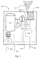
- Figure 1 illustrates a smoke generating entertainment system 1001 comprising a container 1003, a liquid pump 1005, smoke generating means 1007, a controller 1009, an air pump 1011, a power module 1013 and a battery 1015.
- the container comprises smoke/fog/haze liquid
- the liquid pump 1005 pumps the smoke/fog/haze liquid into the smoke generating means 1007, which generates smoke/fog/haze 1017 by atomizing or vaporising the smoke/fog/haze liquid as known in the art.
- the controller is adapted to control the liquid pump 1005, the air pump 1011 and the smoke generator through communication line 1019 for instance in order to activate/deactivate the pumps, increase/decrease liquid flow or regulate the smoke generating means etc.
- the communication line could for instance be carried out as a data bus, a single wire bus or any communication line known in the art of communication.
- the controller could for instance be a microcontroller, computer, microprocessor, printed circuit board or the like.
- the controller can in this embodiment control the entertainment system based on an external communication signal 1021 e.g. based on a DMX protocol or the like, but the entertainment system can also be performed based on a pre-programmed pattern stored in the control unit (1009).
- the system components are supplied with power through an internal power line 1023 which during normal running conditions receives power through the power module 1013, which is connected to an external power source e.g. an AC source.
- the internal power supply could in one embodiment be based on a 12 V DC supply and the power module thus converts the external power supply into 12 V DC.
- the internal power supply system could however in other embodiments be based on other voltages and also on AC.
- the system components would be power supplied by the battery 1015 in case the connection 1025 to the external power source fails or the power module fails.
- the system could be adapted to automatic switching on of the battery backup as soon as the external power supply is disconnected and to be adapted to recharge the battery when the power supply is connected.
- the controller is adapted to start a shut-down process (illustrated in figure 2 and 3 ) in case of malfunctioning of at least a part of the entertainment system, e.g.
- the controller then deactivates the liquid pump 1005 and activates the air pump to purge the liquid pump and smoke generation means during the shutdown process. This prevents progressive build-up of polymerised glycol in the vaporiser resulting in premature failure of the system e.g. in case the system is disconnected from the external power supply and stored.
- the entertainment system comprises furthermore a fluid monitoring 1027 system, which comprises means 1029 for measuring the back pressure from the smoke generator. Introducing fluid to the smoke generator causes a measurable increase in the system pressure and can thus be used to indirectly measure the absence of fluid and indicate a malfunctioning of the system and thus activate the shutdown process.
- the fluid monitoring 1027 system can therefore send a shutdown signal to the controller when it measures a decrease in the back pressure from the smoke generator or when the back pressure has fallen to a lower threshold value. The controller could then start the shut-down process as described below.
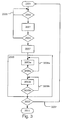
- Figure 2 illustrates a flow diagram of the shut-down process performed by the control means when a malfunction, such as interruption of external/network power, consumption of fog fluid, pump failure etc., occurs.
- the control unit initialises (2001) during start up the shutdown process and a malfunction test (2003) is configured to run continuously or at regular intervals during use of the entertainment system.
- the malfunction test (2003) tests if the entertainment system runs properly, e.g. if it is properly connected to an external/network power supply, if external/network power fails.
- the malfunction test furthermore tests whether or not the smoke liquid has been consumed, the status of the pumps etc. None is done (2005) as long as the entertainment system is running properly.
- the liquid pump pumping liquid into the smoke generator is deactivated (2007) when a malfunction is registered. Thereafter a purging process (2009) cleaning the fluid system is started, e.g. by activating a gas pump purging gas through the fluid system and thus cleaning the smoke generator. The entertainment system is finally turned off (2011) once the cleaning process is completed.
- FIG. 3 illustrates another embodiment of the shutdown process.
- the malfunction test (2003) is in this embodiment performed twice separated by a time delay (3001) in order to verify that the registered malfunction truly occurred.
- the time delay could be any period of time e.g. defining the period of time that the malfunction should have occurred before the shutdown process is continued.
- the cleaning process (2009) comprises in this embodiment the step of running a water pump (3003a) (see figure 4 for illustration of water pump) purging water through the smoke generator.
- the water pump could for instance run for a predetermined period of time until a predetermined amount of water has been purged through the smoke generator or could also be performed a number of times to ensure that all fog/haze/smoke liquid is removed from the smoke generator.
- Step (3005a) therefore represents a test procedure testing the conditions that needs to be fulfilled before moving on to the next step in the shutdown process. The shutdown process thus continues in test loop (3006a) until the test condition(s) is/are fulfilled.
- Similar steps (3003b), (3005b) and (3006b) are performed using an air pump pumping air or another kind of cleaning gas through the smoke generator to dry and blow dirt and liquid leftovers out of the smoke generator.
- This embodiment further comprises a final malfunction test that tests if the malfunction has be repaired, e.g. if the external/network power supply has been reestablished or smoke liquid has been filled into the container and cancels (3007) the shutdown process if this is true. Otherwise the entertainment system is turned off (2011).
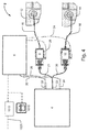
- FIG. 4 shows another embodiment of a smoke generating entertainment system 2.
- the entertainment system comprises a heat storage 4 as described below and controlling means embodied as a printed circuit board 6.
- the system furthermore comprises a liquid system comprising a first water pump 8 and a second glycol pump 10.
- the water is pumped from water storage 12, and the glycol is pumped from glycol storage 14.
- a water line 16 is connected between the water storage 12 and the first water pump 8.
- a liquid line 18 is connected between the glycol storage 14 and the glycol pump 10.
- the pump 8 has an outlet 21, and the pump 10 has an outlet 20.
- the outlets 20 and 21 are combined in a common liquid line 22, which is connected to the heat storage 4.
- the PCB 6 has a first control line 24 leading towards the pump 10 and a second control line 26 connected to the pump 8.
- the PCB has electric connections 28 and 30 leading to the heating element placed in the heat storage where this heating element has terminals 32 and 34.
- the PCB 6 supplies electrical energy through the lines 28 and 30 through the input terminals 32 and 34 to the heating element placed in the heat exchanger. Thereby the heat storage is heated to a sufficient high temperature for generating smoke. Temperature regulations could be preferred so that the heat exchanger is regulated to a controlled maximum temperature.
- the pump 8 and 10 will then start operating and pump water and glycol through the lines 16 and 18 and deliver liquids under pressure through the lines 20, 21 and 22 to the heat storage 4 where the liquid is evaporated.
- the evaporated liquid is then sent through an outlet (not shown) whereby the smoke/fog/haze effects are generated.
- the power consumption in the heating element placed in the heat storage 4 is relatively limited. Therefore operation of the heat exchanger can continue even if the lines 28, 30 are not conducting any power towards the heating element through terminal 32, 34. If only the pumps 8, 10 are operating smoke will be generated by the heat stored in the heat storage 4. Thereby the pumps will be able to operate, if they are connected by a battery supply or by an uninterrupted power supply.
- the entertainment system can comprise at least one pump 8, 10.
- the duration of operation of the pump is controllable by PCB 6 to regulate the density of the smoke screen.
- One way of controlling the density of the smoke is to control the duration of the pump 8, 10.
- the pump could be controlled by pulse with modulation (PWM). By PWM modulation is achieved an effective regulation where the smoke formed continues. In a smoke generator using a heating storage it is not possible to regulate the heating element. Therefore an effective control of the pump is preferred.
- the PCB entertainment system is like the entertainment system described in figure 1 powered by an external power supply 1025 through a power module 1013, and a battery is adapted to provide power upon disconnection of the external power supply 1025 such that the PCB can perform a shutdown process as described above.
- FIG. 5a, 5b, 5c, 5c show respectively a side, front, top and perspective view of a heat storage 4 used in the entertainment system of figure 4 .
- the heat storage 4 comprises a lower section 106 and an upper section 108.
- the lower section 106 comprises an electric heating element 124 which comprises terminals 114 and 116.
- the upper part 108 of the heat storage comprises a second heating element 126 which has inlet terminals 110 and 112.
- the heating storage 4 comprises an inlet 118 which is connected to a channel 122 which channel runs from the inlet 118 to the outlet 120.
- liquid is pumped to the inlet 118 into the channel 122 where this liquid will evaporate before it leaves the channel at the outlet 120.
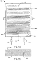
- Figure 6a shows the upper section 108 of a heat storage block 4 illustrated in Figure 5
- figure 6b illustrates the cross section taken along line A-A.
- the upper part 108 of the heat storage block 4 comprises a first terminal 110 and a second terminal 112 connected to a heating element 126 placed in the block 108.
- the heating block 108 comprises a liquid inlet 118 which is connected to a fluid channel 122.
- the channel 122 is limited by walls 601, and the channels 122 have edges 603. Towards the outlet the channel 122 is increased into a channel 605, which channel 605 has a bigger cross-sectional area.
- the channel 605 is connected to an outlet 120.
- the upper section 108 will be covered by the second part of the heating storage block. Fluid is sent through the inlet 118 into the channel 122 in which channel the liquid is heated and the liquid starts boiling and thereby evaporates. Along the channel 122 more and more of the liquid will be converted into steam, and at the outlet 120 the liquid content is supposed to be very small. The liquid is expanding very much by the evaporation, thus the volume of the channel increases over its whole length. This increasing channel cross-sectional area results in a natural reduction of a backflow.
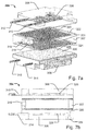
- Figure 7a and 7b illustrate respectively an exploded view and a side view of an alternative embodiment for a heat block 304.
- the figures illustrate the heating storage block 304 comprising an upper section 308 and a lower section 306. Between these two sections are placed a middle section 307.
- the upper section 308 comprises an electric heating element 326 embedded in the material, which electric heating element has a first terminal 310 and a second terminal 312.
- the lower part 306 has an electrical heating element 328 embedded in the material, and this heating element comprises electrical terminals 314 and 316.
- the middle section 307 comprises inlets 318 and 319.
- the middle section comprises channels at the upper and lower side. These channels have the numbers 322 and 324.
- the channels end at an upper outlet 320 and a lower outlet 321, which via two vertical channels 328 and 330 are connected to two outlets (only one 334 illustrated in fig 7b ) at the bottom of the lower section 306.
- the storage capacity is increased, and because there are two channels formed in the middle section the capacity of smoke generation is increased. Furthermore, the total mass in relation to the previously described embodiments is increased. This also means in this embodiment that there is sufficient heat stored in the heat storage means 304 to let the smoke generator operate without power supply for a longer period which is supposed to be as long as 40 minutes. For both embodiments it is important that the heat storage has relatively high heat conductivity to conduct heat towards the channels during operation. Therefore, the heating storage is probably produced of metal.
- One possible metal for this purpose is an aluminium alloy. Other metals or other alloys could be used depending on the heat storage capacity.
Landscapes
- Charge And Discharge Circuits For Batteries Or The Like (AREA)
- Fluid-Pressure Circuits (AREA)
- Cleaning By Liquid Or Steam (AREA)
Description
- The present invention relates to an entertainment system comprising a fluid system comprising smoke generating means, said smoke generating means are supplied from at least one pump connected to at least one container for fluid, which at least one pump is controlled by control means. The present invention furthermore relates to a method for operating an entertainment system.
- Atmospheric effects such as special effect smoke like fog and haze are now seen as a key element in the field of entertainment effects. The use of these atmospheric effects can be found throughout motion pictures and television productions, live theatre, concerts, at nightclubs and raves, amusement and theme parks and even in video arcades and similar venues and are used for creating special effects to make lighting and lighting effects visible and to create a specific sense of mood or atmosphere. If an individual is at an entertainment venue and beams of light are visible cutting across the room, then it is most likely that smoke or fog is being used. Theatrical smoke and fog are indispensable in creating visible mid-air laser effects to entertain audiences, and lighting designers therefore use a fine diffused haze when creating such effects.
- Most smoke/fog/haze machines create the smoke/fog/haze by either vaporizing a water and glycol-based or glycerine-based fluid or by a mineral-oil-based fog via atomization. For glycol-based smoke/fog/haze, the fluid (fog juice) is injected into a heated block and evaporates quickly. The resulting pressure forces the vapour out of the exit. Upon coming into contact with cool outside air the vapour forms a fog. When shutting down a machine of this type, it is important to allow the machine to go through a shut-down process before removing the AC network power from the machine. Failure to do this leads to a progressive build-up of polymerised glycol in the vaporiser resulting in premature failure of the unit. The machines are often used in connection with concerts and road shows where the machines are packed and transported to a new location just as the concert or roads show ends. The machines are as a consequence typically unplugged from the power supply without being properly shut down. Another issue is the fact that the smoke/fog/haze machines eventually consume all fog juice in the container, which also could damage the smoke generator and other parts of the smoke machine, if the machine continues to run after all fog juice have been consumed.
- Furthermore, the machines use a large amount of energy to vaporise the fluid and thus need a large power supply. Large concerts and shows very often comprise a large number of smoke/fog/haze machines, lighting and sound equipment, and the power supply needs to be shared between the different equipment. The power supply might therefore be limited and the smoke/fog/haze machines can as a consequence not be supplied with sufficient power to create the smoke/fog/haze effects.
-
US 3242098 relates to a fog generator where the energy supply is generated by a burner, which burner evaporates water and fog chemical in tube forming a coil around the burning flame. The generated steam in the coil is relieved through an outlet to form fog. -
GB 2 328 874 - It is the object of the invention to achieve a smoke generating entertainment system that solves the above-mentioned problems and improves the lifetime of the entertain-ment system.
- The object of the invention can be fulfilled by a system as described in the preamble to claim 1, which system can be further modified by adapting the control means to per-form a shutdown process upon malfunctioning of at least a part of said entertainment system, and in that said shutdown process performs a purge of at least a part of said fluid system. Hereby it is ensured that the entertainment system is properly shut down, if a malfunction occurs during use of the entertainment system, and that the fluid system is purged whereby progressive build-up of polymerised glycol in the smoke generator resulting in premature failure of the unit is prevented. A malfunction could for instance be interruption of power supply, consumption of the fluid in the container, failure of pumps or smoke generator etc. The shutdown process would thus prevent further damage of the entertainment system upon malfunctioning of one part of the entertainment system, and service expenses are thus decreased, as less damage to the machine occurs.
- The control means are in another embodiment adapted to perform said shutdown upon interruption of power to said entertainment system, and at least a part of said entertainment system is power supplied by a battery during said shutdown process. Hereby it is ensured that the entertainment system is properly shut down in case the power supply is disconnected, as the entertainment system is capable of completing the shut-down process using power from the battery to purge the fluid system. The lifetime of machines that are unplugged from the power supply without being properly shut down is increased, as the entertainment system automatically performs a proper shutdown.
- The entertainment system comprises in another embodiment a fluid monitor measuring fluid pressure of at least a part of said fluid system, and said control means are adapted to perform said shutdown process based on said measured fluid pressure. Hereby it is possible to automatically perform a proper shutdown of the entertainment system in case all the fluid in the container is consumed. The fluid monitor could for instance monitor the back pressure from the smoke generator, as this pressure would decrease in case the system runs out of fluid.
- The entertainment system comprises in another embodiment a gas pump pumping gas through at least a part of said fluid system during said shutdown process. Hereby a gas could be used to purge the fluid system and thus remove fog/smoke/haze fluid leftovers which build-up of polymerised glycol in the smoke generator. Furthermore, such gas could dry the fluid system and thus prevent corrosion of the fluid system.
- The entertainment system comprises in another embodiment a liquid pump pumping liquid through at least a part of said fluid system during said shutdown process. Hereby liquid could be used to purge the fluid system, and the liquid could resolve fog/smoke/haze fluid leftovers and thus remove them from the fluid system. The liquid could for instance be demineralised water, which would not leave any minerals in the fluid system.
- The smoke generating means comprise in another embodiment a heating storage which heating storage comprises at least one first electric heater, which heating storage block comprises at least one flow channel which flow channel comprises a number of turns, which channel has a length that at least is longer than the longest side of the heating storage. By using a large metal block as heat storage it is possible to store energy for evaporating a fluid so that the power demand during operation will be reduced. Using the heating storage will lead to a situation where a power failure will not be able to stop the generation of smoke. If a system comprises an uninterruptible power supply (UPS) or if it is connected to batteries, operation will continue as long as there is power supply and as long as there is still sufficient heating stored in the heat storing means. The heating which is stored will probably last for several minutes and will probably be effective up to 40 minutes. The use of the heating storage block will also reduce the peak power consumption of the smoke generator, as the power consumption of the smoke generator will be more stable compared to the power consumption of previous smoke detectors which are generating steam by immediately heating the liquid.
- The heating storage is in another embodiment formed of at least two sections which sections are fastened towards each other by fastening means. By producing the heating storage block in two sections a channel can be formed in only one of the two sections. This can lead to a situation where one of the sections comprises electrical heating and also comprises the channel at the top. The second section covering the channel can then be a relatively thick flat section where only the mass of the material is used for heat storage. The two sections have to be fastened towards each other. It is possible to screw the sections together but welding seems to be the preferred method.
- A number of entertainment systems are in another embodiment operatively linked by communication means whereby the heating elements operate in time share mode depending on actual heating demand. Hereby it is possible to run several smoke generating entertainment systems simultaneously on the same power line without extending the capacity of the power line as the entertainment systems only consume power when needed.
- In another embodiment at least one of said pumps is a diaphragm pump used for pumping liquids. A diaphragm pump is very robust compared to conventionally used piston pumps and the lifetime of the entertainment system is thus increased.
- The internal system components are in another embodiment powered from a 12V source to allow software controlled shutdown irrespective of the shutdown source or the presence of AC network power.
- The present invention relates also to a method for operating an entertainment system comprising a fluid system comprising smoke generating means, where said smoke generating means are supplied from at least one pump connected to at least one container for fluid, said method comprises the steps of performing a shutdown process upon malfunctioning of at least a part of said entertainment system, and said shutdown process comprises the step of purging at least a part of said fluid system. Hereby the same advantages as described above are achieved.
- The shutdown process is in another embodiment performed upon interruption of power to said entertainment system and said shutdown process comprises the step of power supplying at least a part of said entertainment system by a battery. Hereby the same advantages as described above are achieved.
- The method comprises in another embodiment the step of measuring fluid pressure of at least a part of said fluid system and the step of performing said shutdown process based on said measured fluid pressure. Hereby the same advantages as described above are achieved.
- The shutdown process comprises in another embodiment the step of pumping gas through at least a part of said fluid system. Hereby the same advantages as described above are achieved.
- The shutdown process comprises in another embodiment the step of pumping liquid gas through at least a part of said fluid system. Hereby the same advantages as described above are achieved.
-
-
Figure 1 illustrates an entertainment system according to the present invention; -
Figure 2 illustrates a shutdown process for the entertainment system; -
Figure 3 illustrates another shutdown process for the entertainment system; -
Figure 4 illustrates another entertainment system according to the present invention; -
Figure 5a, 5b, 5c and 5d illustrate a first embodiment of a heating storage block; -
Figure 6a and 6b illustrate a sectional view of a possible embodiment for a heating block; -
Figure 7a and 7b illustrate a second embodiment for the heating block. -
Figure 1 illustrates a smoke generatingentertainment system 1001 comprising acontainer 1003, aliquid pump 1005, smoke generating means 1007, acontroller 1009, anair pump 1011, apower module 1013 and abattery 1015. The container comprises smoke/fog/haze liquid, and theliquid pump 1005 pumps the smoke/fog/haze liquid into the smoke generating means 1007, which generates smoke/fog/haze 1017 by atomizing or vaporising the smoke/fog/haze liquid as known in the art. The controller is adapted to control theliquid pump 1005, theair pump 1011 and the smoke generator throughcommunication line 1019 for instance in order to activate/deactivate the pumps, increase/decrease liquid flow or regulate the smoke generating means etc. The communication line could for instance be carried out as a data bus, a single wire bus or any communication line known in the art of communication. The controller could for instance be a microcontroller, computer, microprocessor, printed circuit board or the like. The controller can in this embodiment control the entertainment system based on anexternal communication signal 1021 e.g. based on a DMX protocol or the like, but the entertainment system can also be performed based on a pre-programmed pattern stored in the control unit (1009). The system components are supplied with power through aninternal power line 1023 which during normal running conditions receives power through thepower module 1013, which is connected to an external power source e.g. an AC source. The internal power supply could in one embodiment be based on a 12 V DC supply and the power module thus converts the external power supply into 12 V DC. The internal power supply system could however in other embodiments be based on other voltages and also on AC. The system components would be power supplied by thebattery 1015 in case theconnection 1025 to the external power source fails or the power module fails. The system could be adapted to automatic switching on of the battery backup as soon as the external power supply is disconnected and to be adapted to recharge the battery when the power supply is connected. The controller is adapted to start a shut-down process (illustrated infigure 2 and3 ) in case of malfunctioning of at least a part of the entertainment system, e.g. interruption of external power supply, consumption of smoke liquid and failure of the fluid system or pumps or other components. The controller then deactivates theliquid pump 1005 and activates the air pump to purge the liquid pump and smoke generation means during the shutdown process. This prevents progressive build-up of polymerised glycol in the vaporiser resulting in premature failure of the system e.g. in case the system is disconnected from the external power supply and stored. - The entertainment system comprises furthermore a
fluid monitoring 1027 system, which comprises means 1029 for measuring the back pressure from the smoke generator. Introducing fluid to the smoke generator causes a measurable increase in the system pressure and can thus be used to indirectly measure the absence of fluid and indicate a malfunctioning of the system and thus activate the shutdown process. Thefluid monitoring 1027 system can therefore send a shutdown signal to the controller when it measures a decrease in the back pressure from the smoke generator or when the back pressure has fallen to a lower threshold value. The controller could then start the shut-down process as described below. -
Figure 2 illustrates a flow diagram of the shut-down process performed by the control means when a malfunction, such as interruption of external/network power, consumption of fog fluid, pump failure etc., occurs. The control unit initialises (2001) during start up the shutdown process and a malfunction test (2003) is configured to run continuously or at regular intervals during use of the entertainment system. The malfunction test (2003) tests if the entertainment system runs properly, e.g. if it is properly connected to an external/network power supply, if external/network power fails. The malfunction test furthermore tests whether or not the smoke liquid has been consumed, the status of the pumps etc. Nothing is done (2005) as long as the entertainment system is running properly. On the other hand the liquid pump pumping liquid into the smoke generator is deactivated (2007) when a malfunction is registered. Thereafter a purging process (2009) cleaning the fluid system is started, e.g. by activating a gas pump purging gas through the fluid system and thus cleaning the smoke generator. The entertainment system is finally turned off (2011) once the cleaning process is completed. -
Figure 3 illustrates another embodiment of the shutdown process. The malfunction test (2003) is in this embodiment performed twice separated by a time delay (3001) in order to verify that the registered malfunction truly occurred. The time delay could be any period of time e.g. defining the period of time that the malfunction should have occurred before the shutdown process is continued. - The cleaning process (2009) comprises in this embodiment the step of running a water pump (3003a) (see
figure 4 for illustration of water pump) purging water through the smoke generator. The water pump could for instance run for a predetermined period of time until a predetermined amount of water has been purged through the smoke generator or could also be performed a number of times to ensure that all fog/haze/smoke liquid is removed from the smoke generator. Step (3005a) therefore represents a test procedure testing the conditions that needs to be fulfilled before moving on to the next step in the shutdown process. The shutdown process thus continues in test loop (3006a) until the test condition(s) is/are fulfilled. Similar steps (3003b), (3005b) and (3006b) are performed using an air pump pumping air or another kind of cleaning gas through the smoke generator to dry and blow dirt and liquid leftovers out of the smoke generator. This embodiment further comprises a final malfunction test that tests if the malfunction has be repaired, e.g. if the external/network power supply has been reestablished or smoke liquid has been filled into the container and cancels (3007) the shutdown process if this is true. Otherwise the entertainment system is turned off (2011). -
Figure 4 shows another embodiment of a smoke generatingentertainment system 2. The entertainment system comprises aheat storage 4 as described below and controlling means embodied as a printedcircuit board 6. The system furthermore comprises a liquid system comprising afirst water pump 8 and asecond glycol pump 10. The water is pumped fromwater storage 12, and the glycol is pumped fromglycol storage 14. Awater line 16 is connected between thewater storage 12 and thefirst water pump 8. Furthermore, aliquid line 18 is connected between theglycol storage 14 and theglycol pump 10. Thepump 8 has anoutlet 21, and thepump 10 has anoutlet 20. Theoutlets common liquid line 22, which is connected to theheat storage 4. ThePCB 6 has afirst control line 24 leading towards thepump 10 and asecond control line 26 connected to thepump 8. Furthermore, the PCB haselectric connections terminals - In a first way of operation the
PCB 6 supplies electrical energy through thelines input terminals - The
pump lines lines heat storage 4 where the liquid is evaporated. The evaporated liquid is then sent through an outlet (not shown) whereby the smoke/fog/haze effects are generated. It is to be understood that the power consumption in the heating element placed in theheat storage 4 is relatively limited. Therefore operation of the heat exchanger can continue even if thelines terminal pumps heat storage 4. Thereby the pumps will be able to operate, if they are connected by a battery supply or by an uninterrupted power supply. - The entertainment system can comprise at least one
pump PCB 6 to regulate the density of the smoke screen. One way of controlling the density of the smoke is to control the duration of thepump - The PCB entertainment system is like the entertainment system described in
figure 1 powered by anexternal power supply 1025 through apower module 1013, and a battery is adapted to provide power upon disconnection of theexternal power supply 1025 such that the PCB can perform a shutdown process as described above. -
Figure 5a, 5b, 5c, 5c show respectively a side, front, top and perspective view of aheat storage 4 used in the entertainment system offigure 4 . Theheat storage 4 comprises alower section 106 and anupper section 108. Thelower section 106 comprises anelectric heating element 124 which comprisesterminals upper part 108 of the heat storage comprises asecond heating element 126 which hasinlet terminals heating storage 4 comprises aninlet 118 which is connected to achannel 122 which channel runs from theinlet 118 to theoutlet 120. - During operation, liquid is pumped to the
inlet 118 into thechannel 122 where this liquid will evaporate before it leaves the channel at theoutlet 120. -
Figure 6a shows theupper section 108 of aheat storage block 4 illustrated inFigure 5 , andfigure 6b illustrates the cross section taken along line A-A. Theupper part 108 of theheat storage block 4 comprises afirst terminal 110 and asecond terminal 112 connected to aheating element 126 placed in theblock 108. Theheating block 108 comprises aliquid inlet 118 which is connected to afluid channel 122. Thechannel 122 is limited bywalls 601, and thechannels 122 haveedges 603. Towards the outlet thechannel 122 is increased into achannel 605, which channel 605 has a bigger cross-sectional area. Thechannel 605 is connected to anoutlet 120. - During operation the
upper section 108 will be covered by the second part of the heating storage block. Fluid is sent through theinlet 118 into thechannel 122 in which channel the liquid is heated and the liquid starts boiling and thereby evaporates. Along thechannel 122 more and more of the liquid will be converted into steam, and at theoutlet 120 the liquid content is supposed to be very small. The liquid is expanding very much by the evaporation, thus the volume of the channel increases over its whole length. This increasing channel cross-sectional area results in a natural reduction of a backflow. -
Figure 7a and 7b illustrate respectively an exploded view and a side view of an alternative embodiment for aheat block 304. Furthermore, the figures illustrate theheating storage block 304 comprising anupper section 308 and alower section 306. Between these two sections are placed amiddle section 307. Theupper section 308 comprises anelectric heating element 326 embedded in the material, which electric heating element has afirst terminal 310 and asecond terminal 312. Furthermore, thelower part 306 has anelectrical heating element 328 embedded in the material, and this heating element compriseselectrical terminals middle section 307 comprisesinlets numbers upper outlet 320 and alower outlet 321, which via twovertical channels fig 7b ) at the bottom of thelower section 306. - By using three-layer heat storage the storage capacity is increased, and because there are two channels formed in the middle section the capacity of smoke generation is increased. Furthermore, the total mass in relation to the previously described embodiments is increased. This also means in this embodiment that there is sufficient heat stored in the heat storage means 304 to let the smoke generator operate without power supply for a longer period which is supposed to be as long as 40 minutes.
For both embodiments it is important that the heat storage has relatively high heat conductivity to conduct heat towards the channels during operation. Therefore, the heating storage is probably produced of metal. One possible metal for this purpose is an aluminium alloy. Other metals or other alloys could be used depending on the heat storage capacity.
Claims (15)
- An entertainment system (1019, 2) comprising a fluid system comprising smoke generating means (1007, 4), said smoke generating means being supplied from at least one pump (1005, 8, 10) connected to at least one container for fluid (1003, 12, 14), wherein the at least one pump (1005, 8, 10) is controlled by control means (1009, 6) characterized in that said control means are adapted to perform a shutdown process upon malfunctioning of at least a part of said entertainment system and in that said shutdown process performs a purge of at least a part of said fluid system.
- An entertainment system according to claim 1 characterized in that said control means (1009, 6) are adapted to perform said shutdown process upon interruption of power (1025) to said entertainment system and in that at least a part of said entertainment system is power supplied by a battery (1015) during said shutdown process.
- An entertainment system according to claims 1-2 characterized in that said entertainment system furthermore comprises a fluid monitor (1027) measuring fluid pressure of at least a part of said fluid system and in that said control means (1009, 6) are adapted to perform said shutdown process based on said measured fluid pressure.
- An entertainment system according to claims 1-3 characterized in that said entertainment system comprises a gas pump (1011) pumping gas through at least a part of said fluid system during said shutdown process.
- An entertainment system according to claims 1-4 characterized in that said entertainment system comprises a liquid pump (1005, 8, 10) pumping liquid through at least a part of said fluid system during said shutdown process
- An entertainment system according to claims 1-5 characterized in that said smoke generating means comprise a heating storage (4, 304), which heating storage (4, 304) comprises at least one first electric heater, which heating storage comprises at least one flow channel (122, 605, 322, 324) which flow channel (122, 605, 322, 324) comprises a number of turns, which channel (122, 605, 322, 324) has a length that at least is longer than the longest side of the heating storage (4,304).
- An entertainment system according to claim 6 characterized in that said heating storage (4, 304) is formed of at least two sections (106,108, 306,307,308) which sections (106,108, 306,307,308) are fastened towards each other by fastening means.
- An entertainment system according to claims 6-7 characterized in that the rate of operation of said at least one pump is controllable by said control means dependent upon the temperature of said heating storage.
- An entertainment system according to one of the claims 1-8 characterized in that at least one of said at least one pump is a diaphragm pump used for pumping liquids.
- An entertainment system according to one of the claims 1-9, characterized in that all internal systems components are powered from an internal power supply to allow software controlled shutdown irrespective of shutdown of external power source or the presence of AC network power.
- Method of operating an entertainment system (1001, 2) comprising a fluid system comprising smoke generating means (1007, 4), where said smoke generating means are supplied from at least one pump (1005, 8, 10) connected to at least one container for fluid (1003, 12,14), wherein the at least one pump is controlled by control means (1009, 6) characterized in that said method comprises the steps of performing a shutdown process upon malfunctioning of at least a part of said entertainment system, and said shutdown process comprises the step of purging (2009, 3003a, 3003b) at least a part of said fluid system.
- Method of operating an entertainment. system according to claim 11 characterized in that said shutdown process is performed upon interruption of power (1025) to said entertainment system, and said shutdown process comprises the step of power supplying at least a part of said entertainment system by a battery (1015).
- Method of operating an entertainment system according to claims 11-12 characterized in that said method comprises the step of measuring fluid pressure of at least a part of said fluid system and by performing said shutdown process based on said measured fluid pressure.
- Method of operating an entertainment system according to claims 11-13 characterized in that said shutdown process comprises the step of pumping gas (3003b) through at least a part of said fluid system.
- Method of operating an entertainment system according to claims 11-14 characterized in that said shutdown process comprises the step of pumping liquid (3003a) through at least a part of said fluid system.
Applications Claiming Priority (2)
| Application Number | Priority Date | Filing Date | Title |
|---|---|---|---|
| DKPA200801034 | 2008-07-23 | ||
| PCT/DK2009/050175 WO2010009733A1 (en) | 2008-07-23 | 2009-07-13 | Smoke generating entertainment system |
Publications (3)
| Publication Number | Publication Date |
|---|---|
| EP2341994A1 EP2341994A1 (en) | 2011-07-13 |
| EP2341994A4 EP2341994A4 (en) | 2013-05-15 |
| EP2341994B1 true EP2341994B1 (en) | 2016-09-07 |
Family
ID=41570033
Family Applications (1)
| Application Number | Title | Priority Date | Filing Date |
|---|---|---|---|
| EP09799997.3A Active EP2341994B1 (en) | 2008-07-23 | 2009-07-13 | Smoke generating entertainment system |
Country Status (4)
| Country | Link |
|---|---|
| US (1) | US8917980B2 (en) |
| EP (1) | EP2341994B1 (en) |
| CN (1) | CN102105199B (en) |
| WO (1) | WO2010009733A1 (en) |
Families Citing this family (17)
| Publication number | Priority date | Publication date | Assignee | Title |
|---|---|---|---|---|
| US9120111B2 (en) | 2012-02-24 | 2015-09-01 | Rain Bird Corporation | Arc adjustable rotary sprinkler having full-circle operation and automatic matched precipitation |
| US9156043B2 (en) | 2012-07-13 | 2015-10-13 | Rain Bird Corporation | Arc adjustable rotary sprinkler with automatic matched precipitation |
| US20150013562A1 (en) | 2013-07-12 | 2015-01-15 | Martin Professionals A/S | Smoke generator and method of controlling a smoke generation |
| TWM478798U (en) * | 2014-01-28 | 2014-05-21 | Wei-Li Tsai | Smoke blowing device |
| CN205235411U (en) * | 2015-11-19 | 2016-05-18 | 广州迪杰帕尔电子科技有限公司 | Fast jet -propelled post stage aerosol sprayer and solenoid valve module thereof |
| WO2018099664A1 (en) * | 2016-11-29 | 2018-06-07 | Philip Morris Products S.A. | Aerosol-generating system and method with dispensing liquid aerosol-forming substrate by pumped air |
| WO2018111879A1 (en) * | 2016-12-12 | 2018-06-21 | Vmr Products Llc | Vaporizer |
| US20180220664A1 (en) * | 2017-02-08 | 2018-08-09 | Fomesa Fruitech, S.L. | Smoke generator container for applying phytosanitary products and method of manufacturing same |
| US10981079B1 (en) * | 2018-06-21 | 2021-04-20 | John R. Goepfert | Fog machine |
| CN110237478B (en) * | 2019-06-04 | 2021-03-26 | 岭澳核电有限公司 | Remote control testing device and method for fire detector of nuclear power station |
| TWI767324B (en) * | 2020-09-14 | 2022-06-11 | 美商神韻藝術品公司 | Dry ice machine for creating fog effect |
| US12343748B2 (en) | 2021-03-16 | 2025-07-01 | Rain Bird Corporation | Multi-mode rotor sprinkler apparatus and method |
| IT202100031616A1 (en) | 2021-12-17 | 2022-03-17 | Ur Fog S R L | BATTERY POWERED MIST GENERATOR WITH INSTANT HEATING |
| US12434252B2 (en) | 2022-04-20 | 2025-10-07 | Rain Bird Corporation | Full-circle and part-circle rotor sprinkler |
| UA127106C2 (en) * | 2022-06-06 | 2023-04-19 | Товариство З Обмеженою Відповідальністю "Джі-Мак" | STEAM GENERATOR FOR SECURITY SYSTEM |
| US12440855B2 (en) | 2022-10-27 | 2025-10-14 | Rain Bird Corporation | Multi-mode rotor sprinkler apparatus and method |
| TWM657322U (en) * | 2023-04-13 | 2024-07-01 | 大陸商廣州市創韋電子科技有限公司 | Waterproof heating module and smoke machine having the module |
Family Cites Families (28)
| Publication number | Priority date | Publication date | Assignee | Title |
|---|---|---|---|---|
| US2315683A (en) * | 1940-07-24 | 1943-04-06 | Taylor Instrument Co | Apparatus for controlling crystal growth |
| GB640266A (en) * | 1947-06-04 | 1950-07-19 | D & P Studios Ltd | An improved method and appliance for creating artificial fog, mist or smoke |
| US3242098A (en) * | 1961-04-03 | 1966-03-22 | Edward F Andrews | Vapor and fog generation |
| GB1039729A (en) * | 1963-12-11 | 1966-08-17 | C F Taylor Electronics Ltd | Smoke generator |
| DE2120749C3 (en) * | 1971-04-28 | 1980-09-04 | Motan Gmbh, 7972 Isny | Spray or fog machine |
| US3861890A (en) * | 1973-05-03 | 1975-01-21 | Alar Eng Corp | Gasoline vapor recovery system and method |
| US3990987A (en) * | 1975-10-01 | 1976-11-09 | The United States Of America As Represented By The Administrator Of The National Aeronautics And Space Administration | Smoke generator |
| US4215549A (en) * | 1977-11-25 | 1980-08-05 | The Garrett Corporation | Turbocharger combustor system |
| US4349723A (en) * | 1980-04-04 | 1982-09-14 | The United States Of America As Represented By The Secretary Of The Navy | Electrically heated non-toxic smoke generator |
| US4326119A (en) * | 1980-04-04 | 1982-04-20 | The United States Of America As Represented By The Secretary Of The Navy | Portable battery operated electric smoke generator |
| US4343719A (en) * | 1980-12-31 | 1982-08-10 | Curtis Dyna-Products | Pulse fog generator |
| US4558196A (en) * | 1983-01-05 | 1985-12-10 | Wolfgang Babasade | Induction smoke regenerator and method for producing natural smoke |
| US4439341A (en) * | 1983-03-21 | 1984-03-27 | The United States Of America As Represented By The Secretary Of The Navy | Smoke generator for use with water and smoke generant |
| US4531375A (en) * | 1984-05-14 | 1985-07-30 | Carrier Corporation | Purge system monitor for a refrigeration system |
| US4764660A (en) * | 1985-10-22 | 1988-08-16 | The United States Of America As Represented By The Secretary Of The Navy | Electric smoke generator |
| US4818843A (en) * | 1988-02-12 | 1989-04-04 | Edmund Swiatosz | Smoke generator |
| CA2061913C (en) * | 1991-02-27 | 1999-12-14 | William R. Wenrich | Smoke generator |
| US5168544A (en) * | 1991-05-31 | 1992-12-01 | Aai Corporation | Method and apparatus for controllably generating simulated smoke |
| GB2315683B (en) * | 1996-07-31 | 1998-09-16 | Barrie Peary | Device for vaporising fluids |
| US5835678A (en) * | 1996-10-03 | 1998-11-10 | Emcore Corporation | Liquid vaporizer system and method |
| US5870524A (en) * | 1997-01-24 | 1999-02-09 | Swiatosz; Edmund | Smoke generator method and apparatus |
| GB2328874B (en) * | 1997-09-05 | 1999-12-01 | Le Maitre Fireworks Limited | Smoke generator |
| CA2216476C (en) * | 1997-09-25 | 2003-07-22 | Norton Marcus Loblick | Smoke generating apparatus |
| US6477890B1 (en) * | 2000-09-15 | 2002-11-12 | K-Line Industries, Inc. | Smoke-producing apparatus for detecting leaks |
| US6789789B2 (en) * | 2002-05-29 | 2004-09-14 | Veeco Instruments Inc. | High throughput vaporizer |
| CN2841116Y (en) * | 2005-09-19 | 2006-11-29 | 鹤山真明丽灯饰有限公司 | Improved smoke machine |
| US7578225B2 (en) * | 2005-12-02 | 2009-08-25 | Garrett Bosch | Smoke generator machine |
| US7529472B2 (en) * | 2005-12-22 | 2009-05-05 | The Boeing Company | Method and apparatus for generating consistent simulated smoke |
-
2009
- 2009-07-13 WO PCT/DK2009/050175 patent/WO2010009733A1/en not_active Ceased
- 2009-07-13 CN CN2009801285462A patent/CN102105199B/en active Active
- 2009-07-13 US US13/054,339 patent/US8917980B2/en active Active
- 2009-07-13 EP EP09799997.3A patent/EP2341994B1/en active Active
Also Published As
| Publication number | Publication date |
|---|---|
| US20110121092A1 (en) | 2011-05-26 |
| CN102105199A (en) | 2011-06-22 |
| WO2010009733A1 (en) | 2010-01-28 |
| CN102105199B (en) | 2013-08-14 |
| EP2341994A1 (en) | 2011-07-13 |
| EP2341994A4 (en) | 2013-05-15 |
| US8917980B2 (en) | 2014-12-23 |
Similar Documents
| Publication | Publication Date | Title |
|---|---|---|
| US8917980B2 (en) | Smoke generating entertainment system | |
| CN108286731B (en) | Artificial fireplace based on steam | |
| US4871115A (en) | Smoke generating apparatus | |
| US20170307223A1 (en) | Electric fireplace simulating realistic flame and smoke effects | |
| US9388989B2 (en) | Fireplace of combusting gasified liquid fuel | |
| JP2016536741A (en) | LED lighting system | |
| CN110121229B (en) | LED lighting system | |
| CN104728822A (en) | Steam generation device with electromagnetic heating function | |
| US7872585B2 (en) | Intruder deterrent system | |
| TW200903935A (en) | Method and apparatus for efficiently operating a gas discharge excimer laser | |
| CN102552018A (en) | Mist Generating Device | |
| US6347188B2 (en) | Smoke generator | |
| JP6032938B2 (en) | Guide light device | |
| EP0534839A1 (en) | Control and monitoring process for a lighting equipment | |
| EP2918909B1 (en) | A liquid fuel portable heater having a thermoelectric generator, and according control method | |
| US20240369259A1 (en) | Fog generator for security system | |
| CA2647124A1 (en) | Boost voltage for fire system notification appliance circuits | |
| KR102629988B1 (en) | Wireless humidifier set | |
| KR102575865B1 (en) | Wireless humidifier set and control method of the same | |
| CN108884994A (en) | Atomizing burners with variable flame rates | |
| EP2323742A1 (en) | A method of creating smoke, fog or haze, and a smoke, fog or haze generator assembly | |
| RU2315232C2 (en) | Electrode steam generator | |
| WO2014093981A1 (en) | Lighting display | |
| JP3250877U (en) | Steam iron | |
| KR101185172B1 (en) | On-and-off bulb irradiated to waterdrops and water foundation apparatus including the strobe light |
Legal Events
| Date | Code | Title | Description |
|---|---|---|---|
| PUAI | Public reference made under article 153(3) epc to a published international application that has entered the european phase |
Free format text: ORIGINAL CODE: 0009012 |
|
| 17P | Request for examination filed |
Effective date: 20110111 |
|
| AK | Designated contracting states |
Kind code of ref document: A1 Designated state(s): AT BE BG CH CY CZ DE DK EE ES FI FR GB GR HR HU IE IS IT LI LT LU LV MC MK MT NL NO PL PT RO SE SI SK SM TR |
|
| AX | Request for extension of the european patent |
Extension state: AL BA RS |
|
| DAX | Request for extension of the european patent (deleted) | ||
| A4 | Supplementary search report drawn up and despatched |
Effective date: 20130417 |
|
| RIC1 | Information provided on ipc code assigned before grant |
Ipc: A63J 5/02 20060101AFI20130411BHEP |
|
| GRAP | Despatch of communication of intention to grant a patent |
Free format text: ORIGINAL CODE: EPIDOSNIGR1 |
|
| RAP1 | Party data changed (applicant data changed or rights of an application transferred) |
Owner name: MARTIN PROFESSIONAL A/S |
|
| INTG | Intention to grant announced |
Effective date: 20160412 |
|
| RAP1 | Party data changed (applicant data changed or rights of an application transferred) |
Owner name: MARTIN PROFESSIONAL APS |
|
| GRAS | Grant fee paid |
Free format text: ORIGINAL CODE: EPIDOSNIGR3 |
|
| GRAA | (expected) grant |
Free format text: ORIGINAL CODE: 0009210 |
|
| AK | Designated contracting states |
Kind code of ref document: B1 Designated state(s): AT BE BG CH CY CZ DE DK EE ES FI FR GB GR HR HU IE IS IT LI LT LU LV MC MK MT NL NO PL PT RO SE SI SK SM TR |
|
| REG | Reference to a national code |
Ref country code: GB Ref legal event code: FG4D |
|
| REG | Reference to a national code |
Ref country code: CH Ref legal event code: EP |
|
| REG | Reference to a national code |
Ref country code: IE Ref legal event code: FG4D |
|
| REG | Reference to a national code |
Ref country code: AT Ref legal event code: REF Ref document number: 826321 Country of ref document: AT Kind code of ref document: T Effective date: 20161015 |
|
| REG | Reference to a national code |
Ref country code: DE Ref legal event code: R096 Ref document number: 602009041020 Country of ref document: DE |
|
| REG | Reference to a national code |
Ref country code: SE Ref legal event code: TRGR |
|
| REG | Reference to a national code |
Ref country code: LT Ref legal event code: MG4D |
|
| REG | Reference to a national code |
Ref country code: NL Ref legal event code: MP Effective date: 20160907 |
|
| PG25 | Lapsed in a contracting state [announced via postgrant information from national office to epo] |
Ref country code: LT Free format text: LAPSE BECAUSE OF FAILURE TO SUBMIT A TRANSLATION OF THE DESCRIPTION OR TO PAY THE FEE WITHIN THE PRESCRIBED TIME-LIMIT Effective date: 20160907 Ref country code: HR Free format text: LAPSE BECAUSE OF FAILURE TO SUBMIT A TRANSLATION OF THE DESCRIPTION OR TO PAY THE FEE WITHIN THE PRESCRIBED TIME-LIMIT Effective date: 20160907 Ref country code: NO Free format text: LAPSE BECAUSE OF FAILURE TO SUBMIT A TRANSLATION OF THE DESCRIPTION OR TO PAY THE FEE WITHIN THE PRESCRIBED TIME-LIMIT Effective date: 20161207 Ref country code: FI Free format text: LAPSE BECAUSE OF FAILURE TO SUBMIT A TRANSLATION OF THE DESCRIPTION OR TO PAY THE FEE WITHIN THE PRESCRIBED TIME-LIMIT Effective date: 20160907 |
|
| REG | Reference to a national code |
Ref country code: AT Ref legal event code: MK05 Ref document number: 826321 Country of ref document: AT Kind code of ref document: T Effective date: 20160907 |
|
| PG25 | Lapsed in a contracting state [announced via postgrant information from national office to epo] |
Ref country code: LV Free format text: LAPSE BECAUSE OF FAILURE TO SUBMIT A TRANSLATION OF THE DESCRIPTION OR TO PAY THE FEE WITHIN THE PRESCRIBED TIME-LIMIT Effective date: 20160907 Ref country code: GR Free format text: LAPSE BECAUSE OF FAILURE TO SUBMIT A TRANSLATION OF THE DESCRIPTION OR TO PAY THE FEE WITHIN THE PRESCRIBED TIME-LIMIT Effective date: 20161208 Ref country code: ES Free format text: LAPSE BECAUSE OF FAILURE TO SUBMIT A TRANSLATION OF THE DESCRIPTION OR TO PAY THE FEE WITHIN THE PRESCRIBED TIME-LIMIT Effective date: 20160907 Ref country code: NL Free format text: LAPSE BECAUSE OF FAILURE TO SUBMIT A TRANSLATION OF THE DESCRIPTION OR TO PAY THE FEE WITHIN THE PRESCRIBED TIME-LIMIT Effective date: 20160907 |
|
| PG25 | Lapsed in a contracting state [announced via postgrant information from national office to epo] |
Ref country code: RO Free format text: LAPSE BECAUSE OF FAILURE TO SUBMIT A TRANSLATION OF THE DESCRIPTION OR TO PAY THE FEE WITHIN THE PRESCRIBED TIME-LIMIT Effective date: 20160907 Ref country code: EE Free format text: LAPSE BECAUSE OF FAILURE TO SUBMIT A TRANSLATION OF THE DESCRIPTION OR TO PAY THE FEE WITHIN THE PRESCRIBED TIME-LIMIT Effective date: 20160907 |
|
| PG25 | Lapsed in a contracting state [announced via postgrant information from national office to epo] |
Ref country code: SK Free format text: LAPSE BECAUSE OF FAILURE TO SUBMIT A TRANSLATION OF THE DESCRIPTION OR TO PAY THE FEE WITHIN THE PRESCRIBED TIME-LIMIT Effective date: 20160907 Ref country code: IS Free format text: LAPSE BECAUSE OF FAILURE TO SUBMIT A TRANSLATION OF THE DESCRIPTION OR TO PAY THE FEE WITHIN THE PRESCRIBED TIME-LIMIT Effective date: 20170107 Ref country code: PT Free format text: LAPSE BECAUSE OF FAILURE TO SUBMIT A TRANSLATION OF THE DESCRIPTION OR TO PAY THE FEE WITHIN THE PRESCRIBED TIME-LIMIT Effective date: 20170109 Ref country code: SM Free format text: LAPSE BECAUSE OF FAILURE TO SUBMIT A TRANSLATION OF THE DESCRIPTION OR TO PAY THE FEE WITHIN THE PRESCRIBED TIME-LIMIT Effective date: 20160907 Ref country code: BG Free format text: LAPSE BECAUSE OF FAILURE TO SUBMIT A TRANSLATION OF THE DESCRIPTION OR TO PAY THE FEE WITHIN THE PRESCRIBED TIME-LIMIT Effective date: 20161207 Ref country code: AT Free format text: LAPSE BECAUSE OF FAILURE TO SUBMIT A TRANSLATION OF THE DESCRIPTION OR TO PAY THE FEE WITHIN THE PRESCRIBED TIME-LIMIT Effective date: 20160907 Ref country code: BE Free format text: LAPSE BECAUSE OF FAILURE TO SUBMIT A TRANSLATION OF THE DESCRIPTION OR TO PAY THE FEE WITHIN THE PRESCRIBED TIME-LIMIT Effective date: 20160907 Ref country code: PL Free format text: LAPSE BECAUSE OF FAILURE TO SUBMIT A TRANSLATION OF THE DESCRIPTION OR TO PAY THE FEE WITHIN THE PRESCRIBED TIME-LIMIT Effective date: 20160907 Ref country code: CZ Free format text: LAPSE BECAUSE OF FAILURE TO SUBMIT A TRANSLATION OF THE DESCRIPTION OR TO PAY THE FEE WITHIN THE PRESCRIBED TIME-LIMIT Effective date: 20160907 |
|
| REG | Reference to a national code |
Ref country code: DE Ref legal event code: R097 Ref document number: 602009041020 Country of ref document: DE |
|
| PG25 | Lapsed in a contracting state [announced via postgrant information from national office to epo] |
Ref country code: IT Free format text: LAPSE BECAUSE OF FAILURE TO SUBMIT A TRANSLATION OF THE DESCRIPTION OR TO PAY THE FEE WITHIN THE PRESCRIBED TIME-LIMIT Effective date: 20160907 |
|
| PLBE | No opposition filed within time limit |
Free format text: ORIGINAL CODE: 0009261 |
|
| STAA | Information on the status of an ep patent application or granted ep patent |
Free format text: STATUS: NO OPPOSITION FILED WITHIN TIME LIMIT |
|
| PG25 | Lapsed in a contracting state [announced via postgrant information from national office to epo] |
Ref country code: DK Free format text: LAPSE BECAUSE OF FAILURE TO SUBMIT A TRANSLATION OF THE DESCRIPTION OR TO PAY THE FEE WITHIN THE PRESCRIBED TIME-LIMIT Effective date: 20160907 |
|
| 26N | No opposition filed |
Effective date: 20170608 |
|
| PG25 | Lapsed in a contracting state [announced via postgrant information from national office to epo] |
Ref country code: SI Free format text: LAPSE BECAUSE OF FAILURE TO SUBMIT A TRANSLATION OF THE DESCRIPTION OR TO PAY THE FEE WITHIN THE PRESCRIBED TIME-LIMIT Effective date: 20160907 |
|
| REG | Reference to a national code |
Ref country code: CH Ref legal event code: PL |
|
| REG | Reference to a national code |
Ref country code: IE Ref legal event code: MM4A |
|
| REG | Reference to a national code |
Ref country code: FR Ref legal event code: ST Effective date: 20180330 |
|
| PG25 | Lapsed in a contracting state [announced via postgrant information from national office to epo] |
Ref country code: LI Free format text: LAPSE BECAUSE OF NON-PAYMENT OF DUE FEES Effective date: 20170731 Ref country code: IE Free format text: LAPSE BECAUSE OF NON-PAYMENT OF DUE FEES Effective date: 20170713 Ref country code: CH Free format text: LAPSE BECAUSE OF NON-PAYMENT OF DUE FEES Effective date: 20170731 |
|
| PG25 | Lapsed in a contracting state [announced via postgrant information from national office to epo] |
Ref country code: FR Free format text: LAPSE BECAUSE OF NON-PAYMENT OF DUE FEES Effective date: 20170731 |
|
| PG25 | Lapsed in a contracting state [announced via postgrant information from national office to epo] |
Ref country code: LU Free format text: LAPSE BECAUSE OF NON-PAYMENT OF DUE FEES Effective date: 20170713 |
|
| REG | Reference to a national code |
Ref country code: DE Ref legal event code: R081 Ref document number: 602009041020 Country of ref document: DE Owner name: HARMAN PROFESSIONAL DENMARK APS, DK Free format text: FORMER OWNER: MARTIN PROFESSIONAL APS, ARHUS, DK |
|
| PG25 | Lapsed in a contracting state [announced via postgrant information from national office to epo] |
Ref country code: MT Free format text: LAPSE BECAUSE OF NON-PAYMENT OF DUE FEES Effective date: 20170713 |
|
| PGFP | Annual fee paid to national office [announced via postgrant information from national office to epo] |
Ref country code: SE Payment date: 20180627 Year of fee payment: 10 |
|
| PG25 | Lapsed in a contracting state [announced via postgrant information from national office to epo] |
Ref country code: MC Free format text: LAPSE BECAUSE OF FAILURE TO SUBMIT A TRANSLATION OF THE DESCRIPTION OR TO PAY THE FEE WITHIN THE PRESCRIBED TIME-LIMIT Effective date: 20160907 Ref country code: HU Free format text: LAPSE BECAUSE OF FAILURE TO SUBMIT A TRANSLATION OF THE DESCRIPTION OR TO PAY THE FEE WITHIN THE PRESCRIBED TIME-LIMIT; INVALID AB INITIO Effective date: 20090713 |
|
| PG25 | Lapsed in a contracting state [announced via postgrant information from national office to epo] |
Ref country code: CY Free format text: LAPSE BECAUSE OF NON-PAYMENT OF DUE FEES Effective date: 20160907 |
|
| PG25 | Lapsed in a contracting state [announced via postgrant information from national office to epo] |
Ref country code: MK Free format text: LAPSE BECAUSE OF FAILURE TO SUBMIT A TRANSLATION OF THE DESCRIPTION OR TO PAY THE FEE WITHIN THE PRESCRIBED TIME-LIMIT Effective date: 20160907 |
|
| REG | Reference to a national code |
Ref country code: SE Ref legal event code: EUG |
|
| PG25 | Lapsed in a contracting state [announced via postgrant information from national office to epo] |
Ref country code: TR Free format text: LAPSE BECAUSE OF FAILURE TO SUBMIT A TRANSLATION OF THE DESCRIPTION OR TO PAY THE FEE WITHIN THE PRESCRIBED TIME-LIMIT Effective date: 20160907 |
|
| PG25 | Lapsed in a contracting state [announced via postgrant information from national office to epo] |
Ref country code: SE Free format text: LAPSE BECAUSE OF NON-PAYMENT OF DUE FEES Effective date: 20190714 |
|
| P01 | Opt-out of the competence of the unified patent court (upc) registered |
Effective date: 20230527 |
|
| PGFP | Annual fee paid to national office [announced via postgrant information from national office to epo] |
Ref country code: GB Payment date: 20250619 Year of fee payment: 17 |
|
| PGFP | Annual fee paid to national office [announced via postgrant information from national office to epo] |
Ref country code: DE Payment date: 20250620 Year of fee payment: 17 |
|
| REG | Reference to a national code |
Ref country code: DE Ref legal event code: R081 Ref document number: 602009041020 Country of ref document: DE Owner name: JEM PROFESSIONAL APS, DK Free format text: FORMER OWNER: HARMAN PROFESSIONAL DENMARK APS, AARHUS, DK |
|
| REG | Reference to a national code |
Ref country code: GB Ref legal event code: 732E Free format text: REGISTERED BETWEEN 20260212 AND 20260218 |