EP2341279A2 - Optical light guide - Google Patents
Optical light guide Download PDFInfo
- Publication number
- EP2341279A2 EP2341279A2 EP11158125A EP11158125A EP2341279A2 EP 2341279 A2 EP2341279 A2 EP 2341279A2 EP 11158125 A EP11158125 A EP 11158125A EP 11158125 A EP11158125 A EP 11158125A EP 2341279 A2 EP2341279 A2 EP 2341279A2
- Authority
- EP
- European Patent Office
- Prior art keywords
- light
- front side
- light transmissive
- fingers
- rear side
- Prior art date
- Legal status (The legal status is an assumption and is not a legal conclusion. Google has not performed a legal analysis and makes no representation as to the accuracy of the status listed.)
- Withdrawn
Links
- 230000003287 optical effect Effects 0.000 title claims abstract description 15
- 239000007787 solid Substances 0.000 claims abstract description 5
- 239000000463 material Substances 0.000 description 3
- 229910052751 metal Inorganic materials 0.000 description 3
- 239000002184 metal Substances 0.000 description 3
- 238000005286 illumination Methods 0.000 description 2
- 238000012986 modification Methods 0.000 description 2
- 230000004048 modification Effects 0.000 description 2
- 239000004033 plastic Substances 0.000 description 2
- RYGMFSIKBFXOCR-UHFFFAOYSA-N Copper Chemical compound [Cu] RYGMFSIKBFXOCR-UHFFFAOYSA-N 0.000 description 1
- NIXOWILDQLNWCW-UHFFFAOYSA-N acrylic acid group Chemical group C(C=C)(=O)O NIXOWILDQLNWCW-UHFFFAOYSA-N 0.000 description 1
- 239000004411 aluminium Substances 0.000 description 1
- 229910052782 aluminium Inorganic materials 0.000 description 1
- XAGFODPZIPBFFR-UHFFFAOYSA-N aluminium Chemical compound [Al] XAGFODPZIPBFFR-UHFFFAOYSA-N 0.000 description 1
- 230000005540 biological transmission Effects 0.000 description 1
- 239000004568 cement Substances 0.000 description 1
- 238000010276 construction Methods 0.000 description 1
- 229910052802 copper Inorganic materials 0.000 description 1
- 239000010949 copper Substances 0.000 description 1
- 230000008878 coupling Effects 0.000 description 1
- 238000010168 coupling process Methods 0.000 description 1
- 238000005859 coupling reaction Methods 0.000 description 1
- 230000001419 dependent effect Effects 0.000 description 1
- 238000012634 optical imaging Methods 0.000 description 1
- 239000004417 polycarbonate Substances 0.000 description 1
- 229920000515 polycarbonate Polymers 0.000 description 1
- 230000000007 visual effect Effects 0.000 description 1
Images




Classifications
-
- G—PHYSICS
- G02—OPTICS
- G02B—OPTICAL ELEMENTS, SYSTEMS OR APPARATUS
- G02B6/00—Light guides; Structural details of arrangements comprising light guides and other optical elements, e.g. couplings
- G02B6/0001—Light guides; Structural details of arrangements comprising light guides and other optical elements, e.g. couplings specially adapted for lighting devices or systems
- G02B6/0011—Light guides; Structural details of arrangements comprising light guides and other optical elements, e.g. couplings specially adapted for lighting devices or systems the light guides being planar or of plate-like form
- G02B6/0013—Means for improving the coupling-in of light from the light source into the light guide
- G02B6/0015—Means for improving the coupling-in of light from the light source into the light guide provided on the surface of the light guide or in the bulk of it
- G02B6/0018—Redirecting means on the surface of the light guide
-
- F—MECHANICAL ENGINEERING; LIGHTING; HEATING; WEAPONS; BLASTING
- F21—LIGHTING
- F21S—NON-PORTABLE LIGHTING DEVICES; SYSTEMS THEREOF; VEHICLE LIGHTING DEVICES SPECIALLY ADAPTED FOR VEHICLE EXTERIORS
- F21S43/00—Signalling devices specially adapted for vehicle exteriors, e.g. brake lamps, direction indicator lights or reversing lights
- F21S43/20—Signalling devices specially adapted for vehicle exteriors, e.g. brake lamps, direction indicator lights or reversing lights characterised by refractors, transparent cover plates, light guides or filters
- F21S43/235—Light guides
- F21S43/236—Light guides characterised by the shape of the light guide
- F21S43/237—Light guides characterised by the shape of the light guide rod-shaped
-
- F—MECHANICAL ENGINEERING; LIGHTING; HEATING; WEAPONS; BLASTING
- F21—LIGHTING
- F21S—NON-PORTABLE LIGHTING DEVICES; SYSTEMS THEREOF; VEHICLE LIGHTING DEVICES SPECIALLY ADAPTED FOR VEHICLE EXTERIORS
- F21S43/00—Signalling devices specially adapted for vehicle exteriors, e.g. brake lamps, direction indicator lights or reversing lights
- F21S43/20—Signalling devices specially adapted for vehicle exteriors, e.g. brake lamps, direction indicator lights or reversing lights characterised by refractors, transparent cover plates, light guides or filters
- F21S43/235—Light guides
- F21S43/236—Light guides characterised by the shape of the light guide
- F21S43/241—Light guides characterised by the shape of the light guide of complex shape
-
- F—MECHANICAL ENGINEERING; LIGHTING; HEATING; WEAPONS; BLASTING
- F21—LIGHTING
- F21S—NON-PORTABLE LIGHTING DEVICES; SYSTEMS THEREOF; VEHICLE LIGHTING DEVICES SPECIALLY ADAPTED FOR VEHICLE EXTERIORS
- F21S43/00—Signalling devices specially adapted for vehicle exteriors, e.g. brake lamps, direction indicator lights or reversing lights
- F21S43/20—Signalling devices specially adapted for vehicle exteriors, e.g. brake lamps, direction indicator lights or reversing lights characterised by refractors, transparent cover plates, light guides or filters
- F21S43/235—Light guides
- F21S43/242—Light guides characterised by the emission area
- F21S43/245—Light guides characterised by the emission area emitting light from one or more of its major surfaces
-
- F—MECHANICAL ENGINEERING; LIGHTING; HEATING; WEAPONS; BLASTING
- F21—LIGHTING
- F21S—NON-PORTABLE LIGHTING DEVICES; SYSTEMS THEREOF; VEHICLE LIGHTING DEVICES SPECIALLY ADAPTED FOR VEHICLE EXTERIORS
- F21S43/00—Signalling devices specially adapted for vehicle exteriors, e.g. brake lamps, direction indicator lights or reversing lights
- F21S43/20—Signalling devices specially adapted for vehicle exteriors, e.g. brake lamps, direction indicator lights or reversing lights characterised by refractors, transparent cover plates, light guides or filters
- F21S43/235—Light guides
- F21S43/249—Light guides with two or more light sources being coupled into the light guide
-
- G—PHYSICS
- G02—OPTICS
- G02B—OPTICAL ELEMENTS, SYSTEMS OR APPARATUS
- G02B6/00—Light guides; Structural details of arrangements comprising light guides and other optical elements, e.g. couplings
- G02B6/0001—Light guides; Structural details of arrangements comprising light guides and other optical elements, e.g. couplings specially adapted for lighting devices or systems
-
- G—PHYSICS
- G02—OPTICS
- G02B—OPTICAL ELEMENTS, SYSTEMS OR APPARATUS
- G02B6/00—Light guides; Structural details of arrangements comprising light guides and other optical elements, e.g. couplings
- G02B6/0001—Light guides; Structural details of arrangements comprising light guides and other optical elements, e.g. couplings specially adapted for lighting devices or systems
- G02B6/0011—Light guides; Structural details of arrangements comprising light guides and other optical elements, e.g. couplings specially adapted for lighting devices or systems the light guides being planar or of plate-like form
- G02B6/0033—Means for improving the coupling-out of light from the light guide
- G02B6/0035—Means for improving the coupling-out of light from the light guide provided on the surface of the light guide or in the bulk of it
- G02B6/0038—Linear indentations or grooves, e.g. arc-shaped grooves or meandering grooves, extending over the full length or width of the light guide
-
- F—MECHANICAL ENGINEERING; LIGHTING; HEATING; WEAPONS; BLASTING
- F21—LIGHTING
- F21K—NON-ELECTRIC LIGHT SOURCES USING LUMINESCENCE; LIGHT SOURCES USING ELECTROCHEMILUMINESCENCE; LIGHT SOURCES USING CHARGES OF COMBUSTIBLE MATERIAL; LIGHT SOURCES USING SEMICONDUCTOR DEVICES AS LIGHT-GENERATING ELEMENTS; LIGHT SOURCES NOT OTHERWISE PROVIDED FOR
- F21K9/00—Light sources using semiconductor devices as light-generating elements, e.g. using light-emitting diodes [LED] or lasers
- F21K9/60—Optical arrangements integrated in the light source, e.g. for improving the colour rendering index or the light extraction
- F21K9/61—Optical arrangements integrated in the light source, e.g. for improving the colour rendering index or the light extraction using light guides
-
- F—MECHANICAL ENGINEERING; LIGHTING; HEATING; WEAPONS; BLASTING
- F21—LIGHTING
- F21Y—INDEXING SCHEME ASSOCIATED WITH SUBCLASSES F21K, F21L, F21S and F21V, RELATING TO THE FORM OR THE KIND OF THE LIGHT SOURCES OR OF THE COLOUR OF THE LIGHT EMITTED
- F21Y2115/00—Light-generating elements of semiconductor light sources
- F21Y2115/10—Light-emitting diodes [LED]
Definitions
- the invention relates to optical light guides and more particularly to an optical light guide for use in a vehicle lamp assembly using LED light sources.
- an optical light guide comprising: a substantially rigid light transmissive body having an input window, a distal end, a front side, and a rear side; said light transmissive body having a substantially smooth exterior surface on said front side and a substantially clear and solid interior, said input window transmitting light into said light transmissive body and extending substantially transverse to a longitudinal axis of a light emitting diode (LED) light source; said light transmissive body having a substantially constant thickness measured between said front side and said rear side, said light transmissive body extending away fiom said input window through an arc of from 60 to 120 degrees to an extension forming an output region extending towards said distal end; said rear side, at least in said output region, being formed with a plurality of reflective steps directing intercepted light towards the front side.
- LED light emitting diode
- Optical light guides formed in accordance with the above description can be permanently mounted in a vehicle and used with replaceable light sources.
- a wide variety of light output designs is possible to achieve decorative and/or utilitarian responses.
- Fig. 1 is plan view of a light source that can be used with the invention
- Fig. 2 is a plan view of an alternate light source that can be used with the invention
- Fig. 3 is a cross-sectional view taken along the line 3-3 of Fig. 1 ;
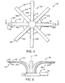
- Fig. 4 is a plan view of an embodiment of the invention.
- Fig. 5 is a sectional view taken along the line 5-5 of Fig. 4 ;
- Fig. 6 is a plan view of an alternate embodiment of the invention.
- Fig. 7 is a sectional view taken along the line 7-7 of Fig. 6 ;
- Fig. 8 is a plan view of another alternate embodiment of the invention.
- Fig. 9 is a sectional view taken along the line 9-9 of Fig. 8 ;
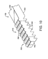
- Fig. 10 is a partial perspective view of a light-directing area employable with the optical light guide of the invention.
- FIG. 1 a replaceable LED lamp assembly 10 comprising that is ideally suited for use with the optical light guide 100 of this invention.
- the lamp 10 has a substantially planar housing 12 transversely arrayed about a longitudinal axis 14 and including a through-hole 16 in a first surface 17 thereof,
- the planar heat conductive support 18 has a front side 20, a backside 22 and a center point 24 coaxial with the longitudinal axis 14.
- LEDs 26 are mounted on the front side 20 and arrayed about the center point 24. In the embodiment shown in Fig. 1 the array is circular and in the embodiment shown in Fig. 2 the array is linear. In a preferred mode there are eight LEDs 26 in each array; however, the actual number will be dependent upon the end use of the light source and, of course, the light output of the individual LEDs.
- a base 28 supports the planar, heat conductive support 18 and is fixed to the housing 12 as desired.
- the base 28 is also thermally conductive so that heat generated by the LEDs during operation is passed through the base 28 to the heat sink 30, which is in thermal contact with the base and extends outwardly of the housing.
- the heat sink 30 can comprise a number of metal rods 30a, the number varying with the size and power of the light source.
- the light source housing has a diameter of 2.5 inches and there can be about 100 metal rods.
- the rods preferably have a length of 0.5 inches. If desired, fins can be utilized in place of the rods 30a.
- a connector 32 is formed with the housing 12 for receiving electrical input to the LEDs and can contain a plurality of electrical contacts, as is known in the art.
- the light source 10 described above can be considered to be a complete unit; however, additional modifications can be made to improve its public reception.
- couplers 34 can be provided on the surface 17 to ease the mounting requirements when the light source 10 is coupled to a receptive body.
- the couplers are suitable for rotational coupling.
- Primary optics can be provided.
- a primary optic 36 in the case of the circular array of Figs. 1 and 3
- 36a in the case of the linear array of Fig. 2
- a primary optic 36 in the case of the circular array of Figs. 1 and 3
- 36a in the case of the linear array of Fig. 2
- optical cement in the case of optical cement
- the light guide 100 comprises a substantially rigid light transmissive body 120 having an input window 140, a distal end 160, a front side 180, and a rear side 200.
- the light transmissive body 120 has a substantially smooth exterior surface on the front side 180 and a substantially clear and solid interior.
- a preferred material for the light guide body is a clear plastic, preferably with low transmissions losses such as acrylic; however if mechanical and thermal robustness is more important, polycarbonate is suggested.
- the input window 140 transmits light received from the LEDs 26 into the light transmissive body 120 and extends substantially transverse to a longitudinal axis 121 of a light emitting diode (LED) light source 26.
- LED light emitting diode
- the light transmissive body 120 has a substantially constant thickness measured between the front side 180 and the rear side 200 and extends away from the input window 140 through an arc of fiom 60 to 120 degrees, with 90' being preferred, to an extension 210 that forms an output region 220 that extends towards the distal end 160.
- the rear side 200 at least in the output region 220 is formed with a plurality of reflective steps 240 directing intercepted light towards the front side 180.
- the front side 180 of the output region 220 can be formed with refractive features 280 directing light received from the reflective steps 240 in a desired direction.
- the refractive feature 280 is shown only in Fig. 10 .
- the extension 210 of the output region 220 comprises about one third of the surface distance from the input window 140 to the distal end 160 while the entire length from the input window 140 to the distal end 160 is more than 10 times the average thickness.
- the light transmissive body 120 is comprised of a plurality of fingers 120a that are radially arrayed around the longitudinal axis 121.
- the number of fingers 120a will, of course, correspond to the number and arrangement of LEDs provided in the lamp assembly 10, which in this case is eight LEDs arranged in a circle, as are the LEDs in the lamp assembly 10 of Fig. 1 .
- the fingers 120a can be arrayed in parallel rows, such as is shown in Figs. 6 and 7 .
- the optical light guide 100 could be used with the lamp assembly 10 shown in Fig. 2 , wherein the LEDs are arrayed in parallel rows.
- the light transmissive body 120 comprises substantially a circular array formed as a body of rotation about the longitudinal axis 121.
- an optical light guide having wide variation in construction to suit specific design purposes. It is adaptable to many light sources but is uniquely adapted to replaceable LED light sources.
- the output regions can be varied to provide a multitude of light outputs that can be utilized with LED lamps of a stabilized design.
Landscapes
- Physics & Mathematics (AREA)
- Engineering & Computer Science (AREA)
- General Engineering & Computer Science (AREA)
- General Physics & Mathematics (AREA)
- Optics & Photonics (AREA)
- Non-Portable Lighting Devices Or Systems Thereof (AREA)
- Optical Couplings Of Light Guides (AREA)
- Light Guides In General And Applications Therefor (AREA)
- Endoscopes (AREA)
Abstract
said light transmissive body substantially being a body of rotation about said longitudinal axis, and having a substantially constant thickness measured between said front side and said rear side, said light transmissive body extending way from said input window through an arc of from 60 to 120 degrees to an extension forming an output region extending towards said distal end; said rear side at least in said output region being formed with a plurality of reflective steps (240) directing intercepted light towards the front side.
Description
- CROSS-REFERENCE TO RELATED APPLICATIONS
- This application claims priority from Provisional Applications Serial Number
601693,254 filed June 23, 2005 601693,999, filed June 24, 2005 - TECHNICAL FIELD
- The invention relates to optical light guides and more particularly to an optical light guide for use in a vehicle lamp assembly using LED light sources.
- BACKGROUND ART
- It is an industry standard that is treated as a necessity to make light sources as small as possible. This saves material costs, and can improve optical imaging. In competition with these needs, large fields areas may need to be illuminated, and with vehicle illumination, a substantial visual image is need on the surface of the vehicle to mark the presence of the vehicle. These goals have been met in the past by the use of relatively large incandescent lamp and reflector systems. The advent of solid-state lighting has pointed in the direction of improving these systems by drastically reducing the size of the light source; however, there is still a need to spread beam-forming illumination over a broad area to better illuminate the vehicle. It would be an advance in the art if such a system could be provided without the necessity of using a reflector. It would be a further advance in the art to provide a lighting system that can utilize replacement light sources.
- DISCLOSURE OF THE INVENTION
- These objects are accomplished, in one aspect of the invention, by the provision of an optical light guide comprising: a substantially rigid light transmissive body having an input window, a distal end, a front side, and a rear side; said light transmissive body having a substantially smooth exterior surface on said front side and a substantially clear and solid interior, said input window transmitting light into said light transmissive body and extending substantially transverse to a longitudinal axis of a light emitting diode (LED) light source; said light transmissive body having a substantially constant thickness measured between said front side and said rear side, said light transmissive body extending away fiom said input window through an arc of from 60 to 120 degrees to an extension forming an output region extending towards said distal end; said rear side, at least in said output region, being formed with a plurality of reflective steps directing intercepted light towards the front side.
- Optical light guides formed in accordance with the above description can be permanently mounted in a vehicle and used with replaceable light sources. A wide variety of light output designs is possible to achieve decorative and/or utilitarian responses.
- BRIEF DESCRTPTION OF THE DRAWINGS
-
Fig. 1 is plan view of a light source that can be used with the invention; -
Fig. 2 is a plan view of an alternate light source that can be used with the invention; -
Fig. 3 is a cross-sectional view taken along the line 3-3 ofFig. 1 ; -
Fig. 4 is a plan view of an embodiment of the invention; -
Fig. 5 is a sectional view taken along the line 5-5 ofFig. 4 ; -
Fig. 6 is a plan view of an alternate embodiment of the invention; -
Fig. 7 is a sectional view taken along the line 7-7 ofFig. 6 ; -
Fig. 8 is a plan view of another alternate embodiment of the invention; -
Fig. 9 is a sectional view taken along the line 9-9 ofFig. 8 ; and -
Fig. 10 is a partial perspective view of a light-directing area employable with the optical light guide of the invention. - BEST MODE FOR CARRYING OUT THE INVENTION
- For a better understanding of the present invention, together with other and further objects, advantages and capabilities thereof, reference is made to the following disclosure and appended claims taken in conjunction with the above-described drawings.
- Referring now to the drawings with greater particularity, there is shown in
FIG. 1 a replaceableLED lamp assembly 10 comprising that is ideally suited for use with theoptical light guide 100 of this invention. Thelamp 10 has a substantiallyplanar housing 12 transversely arrayed about alongitudinal axis 14 and including a through-hole 16 in afirst surface 17 thereof, A planar, heatconductive support 18 of a suitable material, such as any metal, with copper or aluminium preferred, or a thermally conductive plastic, is positioned within thehousing 12. The planar heatconductive support 18 has afront side 20, abackside 22 and acenter point 24 coaxial with thelongitudinal axis 14. -
LEDs 26 are mounted on thefront side 20 and arrayed about thecenter point 24. In the embodiment shown inFig. 1 the array is circular and in the embodiment shown inFig. 2 the array is linear. In a preferred mode there are eightLEDs 26 in each array; however, the actual number will be dependent upon the end use of the light source and, of course, the light output of the individual LEDs. - A base 28 supports the planar, heat
conductive support 18 and is fixed to thehousing 12 as desired. Preferably, the base 28 is also thermally conductive so that heat generated by the LEDs during operation is passed through the base 28 to theheat sink 30, which is in thermal contact with the base and extends outwardly of the housing. Theheat sink 30 can comprise a number ofmetal rods 30a, the number varying with the size and power of the light source. In a preferred embodiment the light source housing has a diameter of 2.5 inches and there can be about 100 metal rods. The rods preferably have a length of 0.5 inches. If desired, fins can be utilized in place of therods 30a. Aconnector 32 is formed with thehousing 12 for receiving electrical input to the LEDs and can contain a plurality of electrical contacts, as is known in the art. - The
light source 10 described above can be considered to be a complete unit; however, additional modifications can be made to improve its public reception. - For example, couplers 34 can be provided on the
surface 17 to ease the mounting requirements when thelight source 10 is coupled to a receptive body. In a preferred embodiment the couplers are suitable for rotational coupling. - Primary optics can be provided. For example, in
Figs. 1, 2 and3 a primary optic 36 (in the case of the circular array ofFigs. 1 and3 ) or 36a (in the case of the linear array ofFig. 2 ) can be bonded directly to theLEDs 26 by means of optical cement. - Referring now to
Fig. 4 , there is shown anoptical light guide 100 that can be utilized with thereplaceable lamp assembly 10. Thelight guide 100 comprises a substantially rigid lighttransmissive body 120 having aninput window 140, adistal end 160, afront side 180, and arear side 200. The lighttransmissive body 120 has a substantially smooth exterior surface on thefront side 180 and a substantially clear and solid interior. A preferred material for the light guide body is a clear plastic, preferably with low transmissions losses such as acrylic; however if mechanical and thermal robustness is more important, polycarbonate is suggested. - The
input window 140 transmits light received from theLEDs 26 into the lighttransmissive body 120 and extends substantially transverse to alongitudinal axis 121 of a light emitting diode (LED)light source 26. - The light
transmissive body 120 has a substantially constant thickness measured between thefront side 180 and therear side 200 and extends away from theinput window 140 through an arc of fiom 60 to 120 degrees, with 90' being preferred, to anextension 210 that forms anoutput region 220 that extends towards thedistal end 160. - The
rear side 200 at least in theoutput region 220 is formed with a plurality ofreflective steps 240 directing intercepted light towards thefront side 180. - The
front side 180 of theoutput region 220 can be formed withrefractive features 280 directing light received from thereflective steps 240 in a desired direction. In the interest of clarity, therefractive feature 280 is shown only inFig. 10 . - The
extension 210 of theoutput region 220 comprises about one third of the surface distance from theinput window 140 to thedistal end 160 while the entire length from theinput window 140 to thedistal end 160 is more than 10 times the average thickness. - In the embodiment shown in
Figs. 4 and 5 the lighttransmissive body 120 is comprised of a plurality offingers 120a that are radially arrayed around thelongitudinal axis 121. The number offingers 120a will, of course, correspond to the number and arrangement of LEDs provided in thelamp assembly 10, which in this case is eight LEDs arranged in a circle, as are the LEDs in thelamp assembly 10 ofFig. 1 . - Alternatively, the
fingers 120a can be arrayed in parallel rows, such as is shown inFigs. 6 and 7 . In this case theoptical light guide 100 could be used with thelamp assembly 10 shown inFig. 2 , wherein the LEDs are arrayed in parallel rows. - Yet another embodiment is shown in
Figs. 8 and 9 where the lighttransmissive body 120 comprises substantially a circular array formed as a body of rotation about thelongitudinal axis 121. - There is thus provided an optical light guide having wide variation in construction to suit specific design purposes. It is adaptable to many light sources but is uniquely adapted to replaceable LED light sources. The output regions can be varied to provide a multitude of light outputs that can be utilized with LED lamps of a stabilized design.
- While there have been shown and described what are at present considered to be the preferred embodiments of the invention, it will be apparent to those skilled in the art that various changes and modifications can be made herein without departing from the scope of the invention as defined by the appended claims.
Claims (5)
- An optical light guide comprising:a substantially rigid light transmissive body having an input window, a distal end, a front side, and a rear side; said light transmissive body having a substantially smooth exterior surface on said front side and a substantially clear and solid interior,said input window transmitting light into said light transmissive body and extending substantially transverse to a longitudinal axis of a light emitting diode (LED) light source;said light transmissive body substantially being a body of rotation about said longitudinal axis, andhaving a substantially constant thickness measured between said front side and said rear side, said light transmissive body extending way from said input window through an arc of from 60 to 120 degrees to an extension forming an output region extending towards said distal end; said rear side at least in said output region being formed with a plurality of reflective steps directing intercepted light towards the front side.
- An optical light guide comprising:a plurality of light guide fingers, each finger having a rigid light transmissive member having an input window, a distal end, a front side, and a rear side;the light transmissive fingers having substantially smooth exterior surface and a substantially clear andsolid interior;the input window transmitting input light into the light transmissive fingers, said input windows being sized and shaped to span at least one LED light source;said light transmissive fingers having a substantially constant thickness measured between the front side andthe rear side, said light transmissive fingers extending way from said input windows through an arc of from 60 to 120 degrees to an output region extending towards said distal end;said rear side at least in the output region being formed with a plurality of reflective steps directing intercepted light towards said front side; and said front side in the output region being formed with refractive features directing light received from the reflective steps in a given direction, said respective output regions being aligned in a common plane.
- The light guide of Claim 2 wherein said fingers are arrayed in parallel rows.
- The light guide of Claim 2 wherein said fingers are arrayed around said longitudinal axis.
- The light guide of Claim 4, wherein said fingers are equally spaced radially with respect to said longitudinal axis.
Applications Claiming Priority (3)
| Application Number | Priority Date | Filing Date | Title |
|---|---|---|---|
| US69325405P | 2005-06-23 | 2005-06-23 | |
| US69399905P | 2005-06-24 | 2005-06-24 | |
| EP06785441A EP1894249A4 (en) | 2005-06-23 | 2006-06-23 | DIRECT OPTICAL LIGHT GUIDE |
Related Parent Applications (1)
| Application Number | Title | Priority Date | Filing Date |
|---|---|---|---|
| EP06785441.4 Division | 2006-06-23 |
Publications (2)
| Publication Number | Publication Date |
|---|---|
| EP2341279A2 true EP2341279A2 (en) | 2011-07-06 |
| EP2341279A3 EP2341279A3 (en) | 2013-01-02 |
Family
ID=37595880
Family Applications (2)
| Application Number | Title | Priority Date | Filing Date |
|---|---|---|---|
| EP11158125A Withdrawn EP2341279A3 (en) | 2005-06-23 | 2006-06-23 | Optical light guide |
| EP06785441A Withdrawn EP1894249A4 (en) | 2005-06-23 | 2006-06-23 | DIRECT OPTICAL LIGHT GUIDE |
Family Applications After (1)
| Application Number | Title | Priority Date | Filing Date |
|---|---|---|---|
| EP06785441A Withdrawn EP1894249A4 (en) | 2005-06-23 | 2006-06-23 | DIRECT OPTICAL LIGHT GUIDE |
Country Status (6)
| Country | Link |
|---|---|
| US (1) | US7375382B2 (en) |
| EP (2) | EP2341279A3 (en) |
| JP (1) | JP5001940B2 (en) |
| KR (1) | KR101372136B1 (en) |
| CA (1) | CA2610870A1 (en) |
| WO (1) | WO2007002403A2 (en) |
Families Citing this family (28)
| Publication number | Priority date | Publication date | Assignee | Title |
|---|---|---|---|---|
| US7932528B2 (en) * | 2005-06-23 | 2011-04-26 | Osram Sylvania Inc. | Segmented optic |
| US7588359B2 (en) * | 2005-09-26 | 2009-09-15 | Osram Sylvania Inc. | LED lamp with direct optical coupling in axial arrangement |
| EP2101202A1 (en) * | 2008-03-10 | 2009-09-16 | Basta France | Light signalling device for a cycle |
| US7837370B2 (en) | 2008-10-10 | 2010-11-23 | Koninklijke Philips Electronics N.V. | Low profile side emission TIR lens for LED |
| KR101810235B1 (en) * | 2009-04-02 | 2017-12-18 | 필립스 라이팅 홀딩 비.브이. | Light emitting device and luminaire |
| JP5363235B2 (en) * | 2009-08-04 | 2013-12-11 | 株式会社小糸製作所 | Vehicle lighting |
| US10359151B2 (en) * | 2010-03-03 | 2019-07-23 | Ideal Industries Lighting Llc | Solid state lamp with thermal spreading elements and light directing optics |
| KR101781424B1 (en) * | 2010-11-26 | 2017-09-26 | 서울반도체 주식회사 | LED Illumination Equipment |
| US8487518B2 (en) * | 2010-12-06 | 2013-07-16 | 3M Innovative Properties Company | Solid state light with optical guide and integrated thermal guide |
| JP2012169116A (en) * | 2011-02-14 | 2012-09-06 | Stanley Electric Co Ltd | Lamp for vehicle |
| JP5178930B1 (en) * | 2011-03-11 | 2013-04-10 | 株式会社東芝 | Lighting device |
| CN102691890A (en) * | 2011-03-21 | 2012-09-26 | 欧司朗股份有限公司 | Omnidirectional lighting device |
| TWM415245U (en) * | 2011-06-30 | 2011-11-01 | Chun Kuang Optics Corp | Optic element and lighting device comprising the optic element |
| US9081125B2 (en) | 2011-08-08 | 2015-07-14 | Quarkstar Llc | Illumination devices including multiple light emitting elements |
| US8708543B2 (en) | 2011-08-10 | 2014-04-29 | Osram Sylvania Inc. | Light engine having distributed remote phosphors |
| JP5930630B2 (en) * | 2011-08-24 | 2016-06-08 | スタンレー電気株式会社 | Lamp |
| US8523407B2 (en) * | 2011-09-13 | 2013-09-03 | Chun Kuang Optics Corp. | Optical element and illuminant device using the same |
| JP5537612B2 (en) * | 2012-07-09 | 2014-07-02 | 株式会社東芝 | Lighting device |
| EP2895794B1 (en) | 2012-09-13 | 2018-06-27 | Quarkstar LLC | Illumination systems providing direct and indirect illumination |
| EP3081846B1 (en) | 2013-07-18 | 2018-03-28 | Quarkstar LLC | Illumination device in which source light injection is non-parallel to device's optical axis |
| CN110553165A (en) | 2013-09-17 | 2019-12-10 | 夸克星有限责任公司 | Light guide illumination device for direct-indirect illumination |
| JP6516301B2 (en) * | 2014-01-03 | 2019-05-22 | シグニファイ ホールディング ビー ヴィ | Optical element, lighting device and lighting apparatus |
| USD732730S1 (en) * | 2014-08-05 | 2015-06-23 | General Luminaire Co., Ltd. | Spliceable lamp panel |
| USD733959S1 (en) * | 2014-08-05 | 2015-07-07 | General Luminaire Co., Ltd. | Spliceable lamp panel |
| JP1535161S (en) * | 2014-09-05 | 2015-10-19 | ||
| JP1535162S (en) * | 2014-09-05 | 2015-10-19 | ||
| CN108613125B (en) * | 2016-12-23 | 2023-11-21 | 市光法雷奥(佛山)汽车照明系统有限公司 | Luminous devices for motor vehicles |
| US12607320B2 (en) * | 2024-08-21 | 2026-04-21 | Ford Global Technologies, Llc | High efficiency light guide |
Citations (3)
| Publication number | Priority date | Publication date | Assignee | Title |
|---|---|---|---|---|
| EP0780265A2 (en) * | 1995-12-21 | 1997-06-25 | Reitter & Schefenacker GmbH & Co. KG | Vehicle rear light |
| EP0900694A2 (en) * | 1997-09-06 | 1999-03-10 | Hella KG Hueck & Co. | Signaling light for vehicle |
| DE10314315A1 (en) * | 2003-03-29 | 2004-10-28 | Preh Gmbh | Operating part e.g. rotary knob, has light distributing part which functions as coded disc for triggering operating function when top part of knob is displaced |
Family Cites Families (19)
| Publication number | Priority date | Publication date | Assignee | Title |
|---|---|---|---|---|
| US692643A (en) * | 1901-08-08 | 1902-02-04 | Alexander S Elmore | Apparatus for separating minerals by selective action of oils. |
| US4875057A (en) | 1988-09-01 | 1989-10-17 | Eastman Kodak Company | Modular optical printhead for hard copy printers |
| CA2299543C (en) * | 1997-08-12 | 2008-02-26 | Decoma International Inc. | Bireflective lens element |
| ES2255737T3 (en) * | 1997-12-09 | 2006-07-01 | Federal-Mogul Ignition Company | WAVE GUIDE STRUCTURES FOR VEHICLE LIGHTING. |
| DE19850443B4 (en) * | 1998-10-23 | 2009-12-31 | Valeo Beleuchtung Deutschland Gmbh | Luminaire, in particular for motor vehicles |
| DE19943589A1 (en) * | 1999-09-11 | 2001-04-05 | Preh Elektro Feinmechanik | Fiber optic |
| DE19943821A1 (en) * | 1999-09-14 | 2001-03-15 | Valeo Beleuchtung Deutschland | Lights, in particular for motor vehicles |
| ES2168071B1 (en) * | 2000-07-12 | 2003-07-16 | Barros Alejandro Rodriguez | MODULAR REAR VIEW MIRROR WITH INTERCHANGEABLE MULTIPLE SIGNALS FOR VEHICLES OF 2, 3, 4 OR MORE WHEELS. |
| US7083315B2 (en) * | 2001-03-26 | 2006-08-01 | Siemens Airfield Solutions | Elevated airfield runway and taxiway edge-lights utilizing light emitting diodes |
| JP3984023B2 (en) * | 2001-11-02 | 2007-09-26 | 株式会社小糸製作所 | Vehicle lamp |
| JP3426226B1 (en) * | 2002-01-10 | 2003-07-14 | 日本ライツ株式会社 | Light guide member, lighting unit and instrument |
| US6565244B1 (en) * | 2002-04-02 | 2003-05-20 | Peterson Manufacturing Company | Single source identification light bar |
| JP2004047351A (en) * | 2002-07-15 | 2004-02-12 | Koito Mfg Co Ltd | Vehicle lighting |
| JP4118647B2 (en) * | 2002-10-24 | 2008-07-16 | 株式会社小糸製作所 | Vehicle sign light |
| FR2853392B1 (en) * | 2003-04-04 | 2006-06-16 | Sli Miniature Lighting Sa | REAR LIGHT, ESPECIALLY STOP LIGHT FOR MOTOR VEHICLE |
| DE10329185A1 (en) * | 2003-06-27 | 2005-01-20 | Guido Kellermann Produktentwicklung & Handel | Light for a vehicle |
| JP2005158362A (en) * | 2003-11-21 | 2005-06-16 | Stanley Electric Co Ltd | Vehicle lighting |
| DE20318691U1 (en) * | 2003-12-03 | 2004-02-26 | Sidler Gmbh & Co. | Light for motor vehicles, has light conductor with steps on outer curved side that viewed towards end output coupling surface are set back and each has end output coupling surface |
| US7341365B2 (en) * | 2005-12-16 | 2008-03-11 | Ford Global Technologies, Llc | LED unit for a vehicle lamp assembly |
-
2006
- 2006-06-05 US US11/447,214 patent/US7375382B2/en not_active Expired - Fee Related
- 2006-06-23 EP EP11158125A patent/EP2341279A3/en not_active Withdrawn
- 2006-06-23 KR KR1020087001798A patent/KR101372136B1/en not_active Expired - Fee Related
- 2006-06-23 WO PCT/US2006/024484 patent/WO2007002403A2/en not_active Ceased
- 2006-06-23 JP JP2008518434A patent/JP5001940B2/en not_active Expired - Fee Related
- 2006-06-23 EP EP06785441A patent/EP1894249A4/en not_active Withdrawn
- 2006-06-23 CA CA002610870A patent/CA2610870A1/en not_active Abandoned
Patent Citations (3)
| Publication number | Priority date | Publication date | Assignee | Title |
|---|---|---|---|---|
| EP0780265A2 (en) * | 1995-12-21 | 1997-06-25 | Reitter & Schefenacker GmbH & Co. KG | Vehicle rear light |
| EP0900694A2 (en) * | 1997-09-06 | 1999-03-10 | Hella KG Hueck & Co. | Signaling light for vehicle |
| DE10314315A1 (en) * | 2003-03-29 | 2004-10-28 | Preh Gmbh | Operating part e.g. rotary knob, has light distributing part which functions as coded disc for triggering operating function when top part of knob is displaced |
Also Published As
| Publication number | Publication date |
|---|---|
| JP5001940B2 (en) | 2012-08-15 |
| KR20080027874A (en) | 2008-03-28 |
| WO2007002403A2 (en) | 2007-01-04 |
| KR101372136B1 (en) | 2014-03-07 |
| EP1894249A2 (en) | 2008-03-05 |
| EP2341279A3 (en) | 2013-01-02 |
| WO2007002403A3 (en) | 2007-12-13 |
| US20060291249A1 (en) | 2006-12-28 |
| EP1894249A4 (en) | 2010-09-29 |
| CA2610870A1 (en) | 2007-01-04 |
| JP2008547175A (en) | 2008-12-25 |
| US7375382B2 (en) | 2008-05-20 |
Similar Documents
| Publication | Publication Date | Title |
|---|---|---|
| US7375382B2 (en) | Direct optical light guide | |
| US6481130B1 (en) | Light emitting diode linear array with lens stripe for illuminated signs | |
| EP2220427B1 (en) | Light distribution using a light emitting diode assembly | |
| KR101186440B1 (en) | Led lamp with direct optical coupling in axial arrangement | |
| US7794117B2 (en) | Lamp cover and illumination lamp having same | |
| CN101529158B (en) | Lighting device | |
| EP1920187B2 (en) | Led headlamp system | |
| US9170007B2 (en) | LED lighting device and system | |
| CN102472472B (en) | Luminaire and the lens being suitable for this luminaire | |
| US7753564B2 (en) | Lampshade and illumination lamp having the same | |
| US20020196623A1 (en) | High efficient tubular light emitting cylinder | |
| US20090154167A1 (en) | Multipurpose light source | |
| WO2013152485A1 (en) | Led light tube for use in fluorescent light fixture | |
| US20070115674A1 (en) | Segmented optic | |
| JP5215312B2 (en) | Lighting device | |
| US20120020077A1 (en) | Led lighting device | |
| CN100573908C (en) | Guided optical light guide | |
| JP2012252990A (en) | Light guide member, fluorescent lamp type led lighting tube using the same, and lighting system | |
| EP2650588A1 (en) | LED light tube for use in fluorescent light fixture | |
| US7172323B1 (en) | Light emitting diode light spreader | |
| US20240093856A1 (en) | 3d printable lens structure | |
| JP2014135117A (en) | Light source device and lighting device including the same | |
| KR20140024946A (en) | Optical semiconductor based tube type lighting apparatus |
Legal Events
| Date | Code | Title | Description |
|---|---|---|---|
| PUAI | Public reference made under article 153(3) epc to a published international application that has entered the european phase |
Free format text: ORIGINAL CODE: 0009012 |
|
| AC | Divisional application: reference to earlier application |
Ref document number: 1894249 Country of ref document: EP Kind code of ref document: P |
|
| AK | Designated contracting states |
Kind code of ref document: A2 Designated state(s): AT BE BG CH CY CZ DE DK EE ES FI FR GB GR HU IE IS IT LI LT LU LV MC NL PL PT RO SE SI SK TR |
|
| PUAL | Search report despatched |
Free format text: ORIGINAL CODE: 0009013 |
|
| AK | Designated contracting states |
Kind code of ref document: A3 Designated state(s): AT BE BG CH CY CZ DE DK EE ES FI FR GB GR HU IE IS IT LI LT LU LV MC NL PL PT RO SE SI SK TR |
|
| RIC1 | Information provided on ipc code assigned before grant |
Ipc: B60Q 1/00 20060101ALI20121127BHEP Ipc: F21S 8/10 20060101AFI20121127BHEP |
|
| 17P | Request for examination filed |
Effective date: 20130702 |
|
| RBV | Designated contracting states (corrected) |
Designated state(s): AT BE BG CH CY CZ DE DK EE ES FI FR GB GR HU IE IS IT LI LT LU LV MC NL PL PT RO SE SI SK TR |
|
| 17Q | First examination report despatched |
Effective date: 20170424 |
|
| STAA | Information on the status of an ep patent application or granted ep patent |
Free format text: STATUS: THE APPLICATION IS DEEMED TO BE WITHDRAWN |
|
| 18D | Application deemed to be withdrawn |
Effective date: 20171107 |