EP2341218A2 - Intershaft seal system for turbo machines - Google Patents
Intershaft seal system for turbo machines Download PDFInfo
- Publication number
- EP2341218A2 EP2341218A2 EP11162887A EP11162887A EP2341218A2 EP 2341218 A2 EP2341218 A2 EP 2341218A2 EP 11162887 A EP11162887 A EP 11162887A EP 11162887 A EP11162887 A EP 11162887A EP 2341218 A2 EP2341218 A2 EP 2341218A2
- Authority
- EP
- European Patent Office
- Prior art keywords
- ring
- seal element
- seal
- seal assembly
- flange
- Prior art date
- Legal status (The legal status is an assumption and is not a legal conclusion. Google has not performed a legal analysis and makes no representation as to the accuracy of the status listed.)
- Granted
Links
- OKTJSMMVPCPJKN-UHFFFAOYSA-N Carbon Chemical compound [C] OKTJSMMVPCPJKN-UHFFFAOYSA-N 0.000 claims abstract description 9
- 229910052751 metal Inorganic materials 0.000 claims abstract description 8
- 239000002184 metal Substances 0.000 claims abstract description 8
- 229910002804 graphite Inorganic materials 0.000 claims abstract description 6
- 239000010439 graphite Substances 0.000 claims abstract description 6
- 229910001092 metal group alloy Inorganic materials 0.000 claims abstract description 6
- 229910052799 carbon Inorganic materials 0.000 claims abstract description 5
- 125000006850 spacer group Chemical group 0.000 claims description 28
- 238000010438 heat treatment Methods 0.000 abstract description 6
- 210000004907 gland Anatomy 0.000 description 18
- 230000000712 assembly Effects 0.000 description 7
- 238000000429 assembly Methods 0.000 description 7
- 238000013519 translation Methods 0.000 description 7
- 230000014616 translation Effects 0.000 description 7
- 230000000694 effects Effects 0.000 description 5
- 239000000463 material Substances 0.000 description 3
- 238000013459 approach Methods 0.000 description 2
- 230000000295 complement effect Effects 0.000 description 2
- 239000012530 fluid Substances 0.000 description 2
- 150000002739 metals Chemical class 0.000 description 2
- 238000000034 method Methods 0.000 description 2
- RTAQQCXQSZGOHL-UHFFFAOYSA-N Titanium Chemical compound [Ti] RTAQQCXQSZGOHL-UHFFFAOYSA-N 0.000 description 1
- 229910045601 alloy Inorganic materials 0.000 description 1
- 239000000956 alloy Substances 0.000 description 1
- 230000004323 axial length Effects 0.000 description 1
- 230000007423 decrease Effects 0.000 description 1
- 230000001419 dependent effect Effects 0.000 description 1
- 238000013461 design Methods 0.000 description 1
- 239000007770 graphite material Substances 0.000 description 1
- 230000003993 interaction Effects 0.000 description 1
- 238000004519 manufacturing process Methods 0.000 description 1
- 230000013011 mating Effects 0.000 description 1
- 239000000203 mixture Substances 0.000 description 1
- 238000013021 overheating Methods 0.000 description 1
- 238000007789 sealing Methods 0.000 description 1
- 239000010936 titanium Substances 0.000 description 1
- 229910052719 titanium Inorganic materials 0.000 description 1
Images


Classifications
-
- F—MECHANICAL ENGINEERING; LIGHTING; HEATING; WEAPONS; BLASTING
- F01—MACHINES OR ENGINES IN GENERAL; ENGINE PLANTS IN GENERAL; STEAM ENGINES
- F01D—NON-POSITIVE DISPLACEMENT MACHINES OR ENGINES, e.g. STEAM TURBINES
- F01D11/00—Preventing or minimising internal leakage of working-fluid, e.g. between stages
- F01D11/003—Preventing or minimising internal leakage of working-fluid, e.g. between stages by packing rings; Mechanical seals
-
- F—MECHANICAL ENGINEERING; LIGHTING; HEATING; WEAPONS; BLASTING
- F16—ENGINEERING ELEMENTS AND UNITS; GENERAL MEASURES FOR PRODUCING AND MAINTAINING EFFECTIVE FUNCTIONING OF MACHINES OR INSTALLATIONS; THERMAL INSULATION IN GENERAL
- F16J—PISTONS; CYLINDERS; SEALINGS
- F16J15/00—Sealings
- F16J15/44—Free-space packings
- F16J15/441—Free-space packings with floating ring
-
- F—MECHANICAL ENGINEERING; LIGHTING; HEATING; WEAPONS; BLASTING
- F05—INDEXING SCHEMES RELATING TO ENGINES OR PUMPS IN VARIOUS SUBCLASSES OF CLASSES F01-F04
- F05D—INDEXING SCHEME FOR ASPECTS RELATING TO NON-POSITIVE-DISPLACEMENT MACHINES OR ENGINES, GAS-TURBINES OR JET-PROPULSION PLANTS
- F05D2260/00—Function
- F05D2260/30—Retaining components in desired mutual position
- F05D2260/38—Retaining components in desired mutual position by a spring, i.e. spring loaded or biased towards a certain position
Definitions
- the invention generally relates to a seal assembly for turbine engines.
- the invention is an intershaft seal capable of providing a seal between inner and outer shafts rotatable about a common axis.
- Intershaft ring seals are designed to operate between co-rotating or counter-rotating shafts.
- a ring seal is typically composed of a carbon graphite material and resides within a generally square-shaped or rectangular-shaped channel, often referred to as a gland, formed between end rings or disposed within an inner shaft.
- a ring seal When a ring seal is installed within an intershaft system, the seal exerts a small force onto the inner diameter of the outer shaft.
- a properly designed ring seal locks onto the outer shaft and spins within the channel or gland. Radial loads along the ring seal are influenced by the pressure between the shafts and centrifugal forces acting on the seal. Axial loads along the ring seal are influenced by the pressure component.
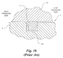
- FIGS. 1a and 1b describe two intershaft seals from the prior art. It is understood that the left hand side of the seal assembly is the high pressure side and the seal rings are seated on the low pressure side of the end ring or the gland groove.
- an intershaft seal assembly 1 including a ring-shaped seal element 2 and spacer ring 6 disposed between a pair of end rings 3, 4. Seal element 2, spacer ring 6, and end rings 3, 4 are further disposed between an outer shaft 10 and an inner shaft 9. End rings 3, 4 have a generally rectangular-shaped cross section and are secured to the inner shaft 9 via a locking ring 5 threaded onto the inner shaft 9 or other means understood in the art.
- the seal element 2 contacts the outer shaft 10.
- a gap 54 is disposed between the seal element 2 and the spacer ring 6.
- the radial height of the gap 54 is sized to avoid contact between the inner diameter of the seal element 2 and the outer diameter of the spacer ring 6 during radial excursions or run-out of the inner shaft 9 and outer shaft 10.
- the spacer ring 6 is secured to the end rings 3, 4 via one or more roll pins 8, each disposed within a pin cavity 7 which traverses the spacer ring 6 and end rings 3, 4.
- FIG. 1b another intershaft seal assembly 1 is shown including a seal element 2 disposed within a ring-shaped gland 43 along an inner shaft 9.
- the seal element 2 contacts the outer shaft 10 so as to form a seal between the inner diameter of the outer shaft 10 and outer diameter of the seal element 2.
- the gland 43 could be machined into the inner shaft 9.
- the axial length of the gland 43 and width of the seal element 2 are tightly controlled to achieve a very tight axial clearance between the seal element 2 and gland 43 so as to minimize leakage of gas from the system.
- the seal element 2 is further forced into the outer shaft 10 by the centrifugal force and pressure loading conditions so as to rotate with the outer shaft 10.
- end rings 3, 4 rotate with the inner shaft 9 and limit axial translation of the seal element 2 along the inner shaft 9.
- the walls of the gland 43 limit axial translation of the seal element 2.
- the coefficient of friction or pressure ratio greatly influences the performance of an intershaft seal assembly 1. If the coefficient of friction is not properly designed, the pneumatic force acting on the seal element 2 in the axial direction could overcome the opposing frictional force. Accordingly, the coefficient of friction should be kept below the implied coefficient of friction to avoid interactions between the seal element 2 and end rings 3, 4 or walls of the gland 43. Otherwise, the pressure force will push the seal element 2 against the end rings 3, 4 or gland 43 causing the seal element 2 to wear and overheat.
- a typical seal element 2 will wear during its break-in period as it contacts the end rings 3, 4 or gland 43. This break-in period is completed when the axial clearance between the seal element 2 and end rings 3, 4 or gland 43 is equal to the combined axial run out of the end rings 3, 4 or gland 43. After the break-in period, the wear rate sharply decreases. However, wear remains a substantial challenge when the relative axial translation between inner shaft 9 and outer shaft 10 is greater than the break-in wear clearance, causing the end rings 3, 4 or gland 43 to "bump" the seal element 2 resulting in one revolution of wear for each axial translation.
- An object of the invention is to provide a seal system capable of avoiding the wear and temperature problems associated with currently available intershaft seal systems.
- the intershaft seal assembly includes a pair of end rings and a seal element. At least one end ring has a flange, with upper and lower surfaces, disposed along and extending from one side of the ring.
- the seal element includes a ring, with inner and outer radial surfaces, and a ring flange, whereby the ring is wider than the ring flange.
- the ring flange is disposed along and extends from the outer radial surface which also contacts the lower surface along at least one flange.
- the seal element is disposed between the end rings so that the ring flange extends beyond the flanges.
- Inner and outer shafts could be either counter-rotating or co-rotating about a common axis-of-rotation.
- the seal element has either a generally inverted T-shaped cross section or a generally L-shaped cross section and at least one end ring has a generally L-shaped cross section.
- the ring flange does not contact the outer shaft and could have a contoured surface adjacent to the outer shaft.
- the seal element and at least one end ring do not rotate separately.
- the assembly further includes a gap disposed between the end rings, seal element, and inner shaft, a spacer bounded by the end rings, gap, and inner shaft, and a locking nut which secures one end ring to the inner shaft.
- the spacer ring is secured to at least one end ring or the seal element is movable between the end rings.
- the seal element is composed of a temperature resistant metal, metal alloy, or carbon graphite, and the seal element has a joint which traverses the seal.
- one end ring is an integral part of the inner shaft.
- a spring is disposed within and contacts a groove along the seal element so as to impart an outward radial force onto the seal element when the inner shaft is stationary or rotating.
- each seal unit, inner shaft, and outer shaft have substantially similar thermal expansion properties to avoid contact between each seal element and outer shaft.
- the invention avoids wear caused by the relative axial movement between the seal element and end ring faces.
- the invention avoids wear along the outer diameter of the seal ring caused by translations between the inner and outer shafts.
- the invention avoids friction induced heating along the seal element, via a substantially non-wearable sealing system, allowing the seal element to be composed of a metal, metal alloy, or carbon graphite, thereby reducing the cost of the seal system.
- the seal assembly 11 is shown including a pair of end rings 13, 14, a seal element 12, an optional gap 17, an optional spacer ring 16, and an optional locking ring 15 disposed between an inner shaft 19 and an outer shaft 20. Elements are disposed about a common centerline 23 or axis-of-rotation.
- a clearance 40 is provided between the inner surface 42 along the outer shaft 20 and a second outer surface 28 along the seal element 12. The height of the clearance 40 should be sufficient to avoid contact between the outer shaft 20 and seal element 12 and to minimize gas leakage across the seal element 12.
- Inner shaft 19 and outer shaft 20 are structures understood in the art which rotate in either a counter-rotational or a co-rotational fashion.
- Each end ring 13 and 14 includes a flange 18 and 21, respectively, so as to have a substantially L-shaped cross section.
- End rings 13, 14 are disposed in a substantially symmetrical arrangement about the seal element 12 and contact the inner shaft 19 so that the flanges 18, 21 are arranged immediately adjacent to but do not contact the outer shaft 20.
- This arrangement forms a structure having a generally inverted T-shaped cross section which complements the cross-sectional design of the seal element 12.
- the seal assembly 11 is designed so as to rotate with the inner shaft 19.
- One end ring 13 could be secured to the inner shaft 19 via a mechanical stop 47 and the other end ring 14 could be secured via a locking ring 15 threaded, pinned, other otherwise fastened or secured onto the inner shaft 19.
- both end rings 13, 14 could be secured to the inner shaft 19 via a pair of locking rings 15 separately disposed at the ends of the seal assembly 11.
- one end ring 13 or 14 to be an integral or unitary part of the inner shaft 19.
- the seal assembly 11 could include a variety of stacking arrangements including additional spacers or the like which contact or are immediately adjacent to the locking ring 15.
- the seal element 12 is disposed between and could contact the end rings 13, 14.
- a spacer ring 16 having an overall diameter less than the seal element 12 also resides between the end rings 13, 14.
- the outer diameter of the spacer ring 16 is less than the inner diameter of the seal element 12 so as to provide a gap 17 between the elements.
- the radial height of the gap 17 is preferred to be dimensioned so as to avoid contact between the inner diameter of the seal element 12 and the outer diameter of the spacer ring 16 during excursions of the inner and outer shafts 19, 20. Seal element 12 and/or spacer ring 16 could contact both end rings 13, 14.
- the seal assembly 11 avoids the problems of temperature and load capacity associated with many fluid-film seals.
- the seal element 12 is a piston ring with a gap and a cross-sectional profile with an inverted T-shape.
- the seal element 12 has an interior flange that mates with the end rings 13, 14 attached to the inner shaft 19. Centrifugal force drives the seal element 12 against the overhang of the end rings 13, 14 and causes the seal element 12 to rotate with the inner shaft 19. Leakage occurs across a controlled clearance at the outer diameter of the seal element 12.
- FIG. 12 shows the leakage as a function of radial clearance and differential pressure for an exemplary system.
- the advantage of the invention is its simplicity and avoidance of fluid-film problems. Since there is no relative movement between the seal element 12 and mating components, the seal element 12 minimizes wear. Materials comprising the end rings 13, 14, spacer ring 16, inner shaft 19, and outer shaft 20 are selected to have substantially similar thermal expansion properties to ensure the clearance 40 between the outer diameter of the seal element 12 and the inner diameter of the outer shaft 20 is closely controlled. The clearance 40 could dynamically vary because of the relative movement between the inner and outer shafts 19, 20.
- the seal element 12, 38 is comprised of a ring 24 and a ring flange 25 disposed about a common centerline 23.
- the ring 24 is a substantially circular element of uniform thickness with a generally square or rectangular cross section between an inner surface 26 and a first outer surface 27.
- the ring flange 25 is a substantially circular structure which extends from the first outer surface 27 along the ring 24.
- the ring flange 25 could have a substantially square or rectangular cross section.
- the cross sectional width of the ring flange 25 is less than the corresponding dimension along the ring 24, as represented in FIGS. 4 and 5 .
- the ring flange 25 is located along the ring 24 in a symmetric or non-symmetric arrangement to form a substantially inverted T-shaped cross section, as represented in FIG. 4 .
- the stepwise cross section of the T-shaped seal element 12 provides a single second outer surface 28, corresponding to the outer diameter of the ring flange 25, disposed between a pair of first outer surfaces 27, corresponding to the interface between the outer diameter of the ring 24 and inner diameter of the ring flange 25.
- the ring flange 25 is positioned at one end of the ring 24 to a form a substantially L-shaped cross section, as represented in FIG. 5 .
- the stepwise cross section of the L-shaped seal element 38 provides a single first outer surface 27, along the interface between the outer diameter of the ring 24 and inner diameter of the ring flange 25, and a single second outer surface 28, along the outer diameter of the ring flange 25.
- ring 24 and ring flange 25 are manufactured from a single or monolithic structure via methods understood in the art. However, it is possible for the ring 24 and ring flange 25 to be separately manufactured and assembled to form the seal element 12 via methods understood in the art.
- the seal element 12 or 38 could include at least one joint 41 which partially or completely transverses the cross section of the element, the latter arrangement allowing the seal element 12, 38 to open outward as centrifugal forces push the seal element 12, 38 against one or both flanges 18, 21.
- the seal element 12, 38 could include two or more such joints 41 facilitating a segmented rather than continuous seal element 12, 38.
- FIG. 3 shows a straight cut joint.
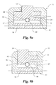
- FIG. 8a shows a tongue and groove joint 41 including a pair of wedge-shaped steps 50a, 50b which interlock to minimize leakage across the joint 41.
- FIG. 8b shows a tongue and groove joint 41 including a pair of rectangular-shaped steps 51 a, 51b which also interlock to minimize leakage across the joint 41.
- Steps 50a, 50b or 51a, 51b are disposed along the seal element 12 or 38 and could traverse the ring 24 and/or the ring flange 25 structures described herein.
- the seal assembly 11 is shown for a seal element 12 with a generally inverted T-shaped cross section.
- the seal element 12 is disposed between the end rings 13, 14 so that the ring 24 is bounded by the end rings 13, 14.
- the ring flange 25 is disposed between the flanges 18, 21 so as to at least extend in a radial fashion beyond the upper surfaces 46, 45 of both flanges 18, 21, respectively.
- a gap 44 disposed between one or both flanges 18, 21 and the vertical walls of the ring flange 25, to ensure that the seal element 12 floats inside the seal assembly 11 and has sufficient radial motion to properly adjust with thermal effects.
- a gap 44 could be disposed between adjacent vertical walls along the ring 24 and one end ring 13.
- a gap 31 could be disposed between the lower surface 30 along one flange 18 and the first outer surface 27 along the ring 24.
- at least one first outer surface 27 should contact the lower surface 29 along the flange 21, because of manufacturing tolerance variations along the outer surfaces 27 of the ring 24 and lower surfaces 29 of the flanges 18, 21.
- no gap 31 is present when components are precision machined so that the upper surfaces 29, 30 of the end rings 13, 14 and first outer surface 27 of the ring 24 are dimensionally identical.
- a spacer ring 16 is provided between the end rings 13, 14 so as to contact the outer surface of the inner shaft 19.
- One or more cavities 32 could traverse the spacer ring 16 about its circumference and one or both end rings 13, 14.
- Roll pins 35 and cavities 32 are complementary shaped so as to allow a roll pin 35 to be inserted into each cavity 32.
- Each cavity 32 along the end rings 13, 14 could be dimensioned to form an interference fit with a roll pin 35, while the cavity 32 through the spacer ring 16 could provide an interference or clearance fit.
- the roll pins 35 secure the seal element 12, end rings 13, 14, and spacer ring 16 so as to form a cartridge-like assembly.
- the spacer ring 16 could be spaced apart from the seal element 12 via a gap 17 of circular extent.
- the gap 17 should have sufficient radial height to accommodate the relative radial motion of the seal element 12 about the cavity 33 because of the clearance fit of the anti-rotation pin 34.
- One or more cavities 33 could completely or partially traverse the seal element 12 about its circumference and one or both end rings 13, 14.
- Anti-rotation pins 34 and cavities 33 are shaped so as to allow an anti-rotation pin 34 to be inserted into each cavity 33.
- Each anti-rotation pin 34 could be press fitted onto the end ring 14 by providing an interference fit between the anti-rotation pin 34 and cavity 33 along the thickness of the end ring 14.
- the cavity 33 portion through the seal element 12 should be larger than the diameter of the anti-rotation pin 34 so as to allow the seal element 12 to slide or move axially and radially in response to mechanical and thermal effects to avoid binding along the seal element 12.
- the cavity 33 portion through the seal element 12 could be either circular or slot-shaped. If movement of the seal element 12 is overly restricted due to inadequate clearance between the diameter of the cavity 33 along the seal element 12 and the diameter of anti-rotation pin 34 therein, the first outer surface 27 along the seal element 12 will not follow and seat onto the lower surface 29 of the flange 21. The result could be an unsteady condition without uniform radial support along the seal element 12 by the flanges18, 21, potentially causing the seal element 12 to crack or explode.
- Other anti-rotation elements and approaches known within the art are applicable.
- Each end ring 13, 14 is preferred to include a relief 37 disposed in a circumferential arrangement at the intersection of the horizontal flange 18, 21 with the vertical structure of each end ring 13, 14, so as to avoid stress concentrations within the end rings 13, 14 and fit and wear problems with the seal element 12.
- the relief 37 could be a radius, if space constraints preclude a relief 37.
- a chamfer could be included at the interfaces of the first outer surface 27 and the vertical face of the ring 24.
- the left hand side of the seal assembly 11 is the high pressure side.
- the seal element 12 seats onto the low pressure side of the end ring 14.
- the joint 41 includes a space which is compressed when the seal element 12 is assembled to form a seal assembly 11.
- the first outer surface 27 seats and seals onto the lower surface 29. If the tension along the seal element 12 is inadequate to radially seat the first outer surface 27 against lower surface 29, an expander spring 48 could be used along the inner diameter of the seal element 12, as shown in FIGS. 9a and 9b .
- centrifugal force seats the seal element 12 as the inner shaft 19 rotates; however, the tension described herein is required along the seal element 12 in order to properly seat the seal element 12 when the inner shaft 19 is stationary.
- the gap 17, 22 should be sufficiently large to accommodate thermally-induced expansion variations along the inner diameter of the seal element 12, 38; whereas, the gap 54 in FIG. 1a accommodates movement of the seal element 2 when inner and outer shafts 9, 10 are eccentrically aligned.
- the segment of the cavity 33 within the seal element 12, 38 is sized to likewise accommodate thermally-induced expansion variations along the seal element 12, 38. Accordingly, the size and shape of the cavity 33 within the seal element 12, 38 could differ from the portion of the cavity 33 disposed along the end ring 14.
- the clearance 40 in FIG. 2 is well defined, since the outer shaft 20 should not contact the seal element 12, 38.
- the end rings 13, 14 restrict radial movement of the seal element 12 and 38, thus avoiding the radial excursions possible by the seals described in FIGS. 1a and 1b .
- the seal assembly 11 from FIG. 4 is shown having a seal element 38 with a generally L-shaped cross section composed of a ring 24 and ring flange 25.
- the seal element 38 is disposed between a generally planar-shaped end ring 36 and an L-shaped end ring 14 so that the ring 24 is bounded by both end rings 14, 36.
- the ring flange 25 is disposed between the end ring 36 and a flange 21 extending from the second end ring 14 so as to at least extend in a radial fashion beyond the upper surface 45 of the flange 21.
- a gap 44 disposed between the vertical sides of flange 21 and/or the end ring 36 and the vertical walls of the ring flange 25, to ensure that the seal element 38 floats inside the seal assembly 11 and has sufficient radial motion to properly adjust to thermal effects.
- the first outer surface 27 should contact the lower surface 29 along the flange 21.
- a spacer ring 16 is provided between the end rings 14, 36 so as to contact the outer surface of the inner shaft 19.
- One or more cavities 32 could traverse the spacer ring 16 about its circumference and one or both end rings 14, 36.
- Roll pins 35 and cavities 32 are complementary shaped so as to allow a roll pin 35 to be inserted into each cavity 32.
- the roll pins 35 secure the seal element 38, end rings 14, 36, and spacer ring 16 so as to form a cartridge-like assembly, providing a structure which is readily shippable and handle-able.
- Each cavity 32 along the end rings 14, 36 could provide an interference fit with the roll pin 35, while the cavity 32 along the spacer ring 16 could provide either an interference or clearance fit.
- the spacer ring 16 could be separated from the seal element 38 via a gap 22 of circular extent.
- the gap 22 should have sufficient radial height to accommodate the relative radial motion of the seal element 38 about the cavity 33 because of the clearance fit of the anti-rotation pin 34.
- One or more cavities 33 could completely or partially traverse the seal element 38 about its circumference and one or both end rings 14, 36.
- Anti-rotation pins 34 and cavities 33 are shaped so as to allow an anti-rotation pin 34 to be inserted into each cavity 33.
- other anti-rotation elements and approaches known within the art are likewise applicable to the embodiments described herein.
- Each anti-rotation pin 34 should be press fitted onto the end ring 14 by providing an interference fit between anti-rotation pin 34 and cavity 33 along the thickness of the end ring 14.
- the cavity 33 portion along the seal element 38 should be larger than the diameter of the anti-rotation pin 34 so as to allow the seal element 38 to slide or move axially and radially in response to mechanical and thermal effects without binding the seal element 12.
- the cavity 33 along the seal element 38 could be either circular or slot-shaped. If movement of the seal element 38 is overly restricted due to inadequate clearance between the diameter of the cavity 33 along the seal element 12 and the diameter of anti-rotation pin 34 therein, the first outer surface 27 along the seal element 38 would not follow and seat onto the lower surface 29 of the flange 21, as described herein.
- the end ring 14 is preferred to include a relief 37 disposed in a circumferential arrangement at the intersection of the horizontal flange 21 with the vertical structure of the end ring 14, so as to avoid stress concentrations therein and fit and wear problems with the seal element 38.
- the relief 37 could include a radius depending on space constraints.
- seal and/or wear purposes it might be advantageous for seal and/or wear purposes to include a non-linear profile along the second outer surface 28 of the seal elements 12, 38 shown in FIGS. 4 and 5 , respectively.
- an inverted T-shaped seal element 12 is shown having a generally concave-shaped upper surface 39 along the ring flange 25. Remaining features of the ring 24, namely, first outer surface 27 and inner surface 26 are as described herein.
- an L-shaped seal element 38 is shown having a generally concave-shaped upper surface 39 along the ring flange 25. Remaining features of the ring 24, namely, first outer surface 27 and inner surface 26 are as described herein.
- contoured geometries composed of one or more concave, convex, and/or linear segments are likewise possible along the upper surface 39.
- the upper surface 39 could be molded onto or machined or shaped into an otherwise linear profile along the outermost diametrical surface of a seal element 12, 38.
- FIGS. 9a and 9b show a spring 48 disposed along a groove 49 about the inner diameter 52 of the inverted T-shaped seal element 12 and L-shaped seal element 38, respectively.
- the spring 48 could be a garter spring, expander spring, or the like.
- the groove 49 is a semi-circular structure disposed along the seal element 12, 38 which approximates the curvature of the spring 48.
- the spring 48 imparts a radial force to seat the outer surface 27 of the seal element 12, 38 onto the lower surfaces 29 and/or 30 as the inner shaft 19 rotates.
- the spring 48 could exert an outward radial force onto the seal element 12, 38 when the seal element 12, 38 is stationary.
- seal assemblies 11 comprised of T-shaped seal elements 12 and/or L-shaped seal elements 38 described herein, in a stacked or serial fashion between an inner shaft 19 and an outer shaft 20.
- Seal assemblies 11 could be secured to the inner shaft 19 between a mechanical stop 47 and a locking ring 5, however other arrangements are possible.
- the total number of seal assemblies 11 is dependent on the space constraints along the inner shaft 19.
- the seal assemblies 11 are constructed as described herein.
- the innermost end rings 14, 13 identified in FIG. 10 are replaced by a single intermediate ring 53 having a generally T-shaped cross section. Both multi-seal assemblies reduce the total flow of air across the seal system.
- the seal elements 12, 38 described herein could be composed of high-temperature, carbon-graphite compositions known within the art.
- An advantage of carbon-graphite is its ability to wear without damage, unlike metals, when the relative movement between the inner and outer shafts 19, 20 exceeds the clearance 40 represented in FIG. 2 .
- the invention described herein also allows for the use of high-temperature metal and metal alloys because the seal assembly 11 avoids the wear problems associated with dual-shaft systems.
- Exemplary metal and metal alloys could include, but are not limited to, 17-4 PH, 410 SS, titanium, and Inconel-X ® (the registered trademark of the Huntington Alloys Corporation of Huntington, West Virginia). Metals further allow the matching of thermal expansion coefficients for materials composing the inner and outer shafts 19, 20, seal element 12 or 38, and end rings 13, 14 or 14, 36.
- the intershaft seal and variations thereof described herein minimize wear and heating problems common to intershaft seal systems.
- the invention is expected to be used within applications wherein a housing is provided with a plurality of interior sections having rotating parts passing there through, wherein one of the interior housing sections must be isolated from another by means of a seal system.
- a seal system is a turbine engine.
Abstract
Description
- The invention generally relates to a seal assembly for turbine engines. Specifically, the invention is an intershaft seal capable of providing a seal between inner and outer shafts rotatable about a common axis.
- Intershaft ring seals are designed to operate between co-rotating or counter-rotating shafts. A ring seal is typically composed of a carbon graphite material and resides within a generally square-shaped or rectangular-shaped channel, often referred to as a gland, formed between end rings or disposed within an inner shaft. When a ring seal is installed within an intershaft system, the seal exerts a small force onto the inner diameter of the outer shaft. During operation, a properly designed ring seal locks onto the outer shaft and spins within the channel or gland. Radial loads along the ring seal are influenced by the pressure between the shafts and centrifugal forces acting on the seal. Axial loads along the ring seal are influenced by the pressure component. Ring seals are designed to have adequate radial loading to prevent the axial load from pushing the seal onto the low pressure end of the channel.
FIGS. 1a and1b describe two intershaft seals from the prior art. It is understood that the left hand side of the seal assembly is the high pressure side and the seal rings are seated on the low pressure side of the end ring or the gland groove. - In
FIG. 1a , anintershaft seal assembly 1 is shown including a ring-shaped seal element 2 andspacer ring 6 disposed between a pair ofend rings Seal element 2,spacer ring 6, andend rings outer shaft 10 and aninner shaft 9.End rings inner shaft 9 via alocking ring 5 threaded onto theinner shaft 9 or other means understood in the art. Theseal element 2 contacts theouter shaft 10. Agap 54 is disposed between theseal element 2 and thespacer ring 6. The radial height of thegap 54 is sized to avoid contact between the inner diameter of theseal element 2 and the outer diameter of thespacer ring 6 during radial excursions or run-out of theinner shaft 9 andouter shaft 10. In some embodiments, thespacer ring 6 is secured to theend rings more roll pins 8, each disposed within apin cavity 7 which traverses thespacer ring 6 andend rings - In
FIG. 1b , anotherintershaft seal assembly 1 is shown including aseal element 2 disposed within a ring-shaped gland 43 along aninner shaft 9. Theseal element 2 contacts theouter shaft 10 so as to form a seal between the inner diameter of theouter shaft 10 and outer diameter of theseal element 2. Thegland 43 could be machined into theinner shaft 9. The axial length of thegland 43 and width of theseal element 2 are tightly controlled to achieve a very tight axial clearance between theseal element 2 andgland 43 so as to minimize leakage of gas from the system. - In both systems described above, the
seal element 2 is further forced into theouter shaft 10 by the centrifugal force and pressure loading conditions so as to rotate with theouter shaft 10. In the first system,end rings inner shaft 9 and limit axial translation of theseal element 2 along theinner shaft 9. In the second system, the walls of thegland 43 limit axial translation of theseal element 2. - Forces act on the
seal element 2 from all sides. On the low pressure side, a pressure drop occurs from high to low pressure from the inner diameter to outer diameter of theseal element 2. The centrifugal loading on theseal element 2 together with radial pressure loads produce a force at the interface between theseal element 2 andouter shaft 10. Axial translation of theseal element 2 is resisted by the friction between theseal element 2 andouter shaft 10. For theseal element 2 to be in equilibrium, the difference in axial forces acting on theseal element 2 must equal the friction force that opposes translation. The relative motion between theseal element 2 andend rings gland 43 is the sum of the inner and outer shaft speeds in counter-rotating applications and the difference of the inner and outer shaft speeds in co-rotating applications. - The coefficient of friction or pressure ratio greatly influences the performance of an
intershaft seal assembly 1. If the coefficient of friction is not properly designed, the pneumatic force acting on theseal element 2 in the axial direction could overcome the opposing frictional force. Accordingly, the coefficient of friction should be kept below the implied coefficient of friction to avoid interactions between theseal element 2 andend rings gland 43. Otherwise, the pressure force will push theseal element 2 against theend rings gland 43 causing theseal element 2 to wear and overheat. - Wear and heating along the
seal element 2 are minimized by planar contact surfaces between theseal element 2 andend rings gland 43; however, wear and heating remain a significant challenge for most intershaft systems. Fluid films are sometimes used between aseal element 2 andend rings gland 43 to reduce wear via the introduction of hydrodynamic bearing structures such as Rayleigh pads or spiral grooves along the faces of theseal element 2 orend rings - A
typical seal element 2 will wear during its break-in period as it contacts theend rings gland 43. This break-in period is completed when the axial clearance between theseal element 2 andend rings gland 43 is equal to the combined axial run out of theend rings gland 43. After the break-in period, the wear rate sharply decreases. However, wear remains a substantial challenge when the relative axial translation betweeninner shaft 9 andouter shaft 10 is greater than the break-in wear clearance, causing theend rings gland 43 to "bump" theseal element 2 resulting in one revolution of wear for each axial translation. - As is readily apparent from the discussions above, the related arts do not include an intershaft seal capable of minimizing wear and heating during use.
- Accordingly, what is required is a seal system capable of avoiding the wear and temperature problems associated with currently available intershaft seal systems.
- An object of the invention is to provide a seal system capable of avoiding the wear and temperature problems associated with currently available intershaft seal systems.
- In accordance with embodiments of the invention, the intershaft seal assembly includes a pair of end rings and a seal element. At least one end ring has a flange, with upper and lower surfaces, disposed along and extending from one side of the ring. The seal element includes a ring, with inner and outer radial surfaces, and a ring flange, whereby the ring is wider than the ring flange. The ring flange is disposed along and extends from the outer radial surface which also contacts the lower surface along at least one flange. The seal element is disposed between the end rings so that the ring flange extends beyond the flanges. Inner and outer shafts could be either counter-rotating or co-rotating about a common axis-of-rotation.
- In accordance with preferred embodiments of the invention, the seal element has either a generally inverted T-shaped cross section or a generally L-shaped cross section and at least one end ring has a generally L-shaped cross section.
- In accordance with yet other embodiments of the invention, the ring flange does not contact the outer shaft and could have a contoured surface adjacent to the outer shaft.
- In accordance with further embodiments of the invention, the seal element and at least one end ring do not rotate separately.
- In accordance with still other embodiments of the invention, the assembly further includes a gap disposed between the end rings, seal element, and inner shaft, a spacer bounded by the end rings, gap, and inner shaft, and a locking nut which secures one end ring to the inner shaft.
- In accordance with still yet other embodiments of the invention, the spacer ring is secured to at least one end ring or the seal element is movable between the end rings.
- In accordance with still further embodiments of the invention, the seal element is composed of a temperature resistant metal, metal alloy, or carbon graphite, and the seal element has a joint which traverses the seal.
- In accordance with still yet further embodiments, one end ring is an integral part of the inner shaft.
- In accordance with still other embodiments, a spring is disposed within and contacts a groove along the seal element so as to impart an outward radial force onto the seal element when the inner shaft is stationary or rotating.
- In accordance with still further yet other embodiments, each seal unit, inner shaft, and outer shaft have substantially similar thermal expansion properties to avoid contact between each seal element and outer shaft.
- Several advantages are offered by the invention. The invention avoids wear caused by the relative axial movement between the seal element and end ring faces. The invention avoids wear along the outer diameter of the seal ring caused by translations between the inner and outer shafts. The invention avoids friction induced heating along the seal element, via a substantially non-wearable sealing system, allowing the seal element to be composed of a metal, metal alloy, or carbon graphite, thereby reducing the cost of the seal system.
- Additional aspects, features, and advantages of the invention will be understood and will become more readily apparent when the invention is considered in the light of the following description made in conjunction with the accompanying drawings, wherein:
-
FIG. 1a is a cross sectional view of a prior art seal assembly disposed between a pair of rotating shafts; -
FIG. 1b is a cross sectional view of a prior art seal element disposed within a gland between a pair of rotating shafts; -
FIG. 2 is a cross sectional view illustrating a seal assembly with an inverted and generally T-shaped seal element disposed between a pair of rotating shafts in accordance with an embodiment of the invention; -
FIG. 3 is a side elevation view illustrating a seal element in accordance with an embodiment of the invention; -
FIG. 4 is an enlarged cross sectional view illustrating a seal assembly with an inverted generally T-shaped seal element in accordance with an embodiment of the invention; -
FIG. 5 is an enlarged cross sectional view illustrating a seal assembly with a generally L-shaped seal element in accordance with an embodiment of the invention; -
FIG. 6 is an enlarged cross sectional view illustrating an inverted and generally T-shaped seal element with contoured upper surface in accordance with an embodiment of the invention; -
FIG. 7 is an enlarged cross sectional view illustrating a generally L-shaped seal element with contoured upper surface in accordance with an embodiment of the invention; -
FIG. 8a is an enlarged perspective view illustrating a step joint formed by interlocking wedge-shaped steps in accordance with an embodiment of the invention; -
FIG. 8b is an enlarged perspective view illustrating a step joint formed by interlocking rectangular-shaped steps in accordance with an embodiment of the invention; -
FIG. 9a is an enlarged cross sectional view illustrating a T-shaped seal element having a spring disposed along the inner diameter thereof in accordance with an embodiment of the invention; -
FIG. 9b is an enlarged cross sectional view illustrating an L-shaped seal element having a spring disposed along the inner diameter thereof in accordance with an embodiment of the invention; -
FIG. 10 is a cross sectional view illustrating a serial arrangement of seal assemblies disposed between an inner shaft and an outer shaft in accordance with an embodiment of the invention; -
FIG. 11 is a cross sectional view illustrating a serial arrangement of seal assemblies with a shared intermediate ring disposed between an inner shaft and an outer shaft in accordance with an embodiment of the invention; and -
FIG. 12 is an exemplary plot showing leakage versus radial clearance in accordance with an embodiment of the invention. - This application is based upon and claims priority from
U.S. Non-Provisional Application No. 12/210,246 filed September 15, 2008 - Reference will now be made in detail to several preferred embodiments of the invention that are illustrated in the accompanying drawings. Wherever possible, same or similar reference numerals are used in the drawings and the description to refer to the same or like parts or steps. The drawings are in simplified form and are not to precise scale. The terms inner, outer, lower, upper, vertical, and horizontal are for descriptive purposes and are not intended to limit the intended scope of the invention and its various embodiments.
- Referring now to
FIG. 2 , theseal assembly 11 is shown including a pair of end rings 13, 14, aseal element 12, anoptional gap 17, anoptional spacer ring 16, and anoptional locking ring 15 disposed between aninner shaft 19 and anouter shaft 20. Elements are disposed about acommon centerline 23 or axis-of-rotation. Aclearance 40 is provided between theinner surface 42 along theouter shaft 20 and a secondouter surface 28 along theseal element 12. The height of theclearance 40 should be sufficient to avoid contact between theouter shaft 20 andseal element 12 and to minimize gas leakage across theseal element 12.Inner shaft 19 andouter shaft 20 are structures understood in the art which rotate in either a counter-rotational or a co-rotational fashion. - Each
end ring flange seal element 12 and contact theinner shaft 19 so that theflanges outer shaft 20. This arrangement forms a structure having a generally inverted T-shaped cross section which complements the cross-sectional design of theseal element 12. - The
seal assembly 11 is designed so as to rotate with theinner shaft 19. Oneend ring 13 could be secured to theinner shaft 19 via amechanical stop 47 and theother end ring 14 could be secured via alocking ring 15 threaded, pinned, other otherwise fastened or secured onto theinner shaft 19. It is likewise possible for both end rings 13, 14 to be secured to theinner shaft 19 via a pair of locking rings 15 separately disposed at the ends of theseal assembly 11. It is further possible for oneend ring inner shaft 19. Also, theseal assembly 11 could include a variety of stacking arrangements including additional spacers or the like which contact or are immediately adjacent to the lockingring 15. - The
seal element 12 is disposed between and could contact the end rings 13, 14. Aspacer ring 16 having an overall diameter less than theseal element 12 also resides between the end rings 13, 14. In preferred embodiments, the outer diameter of thespacer ring 16 is less than the inner diameter of theseal element 12 so as to provide agap 17 between the elements. The radial height of thegap 17 is preferred to be dimensioned so as to avoid contact between the inner diameter of theseal element 12 and the outer diameter of thespacer ring 16 during excursions of the inner andouter shafts Seal element 12 and/orspacer ring 16 could contact both end rings 13, 14. - The
seal assembly 11 avoids the problems of temperature and load capacity associated with many fluid-film seals. Theseal element 12 is a piston ring with a gap and a cross-sectional profile with an inverted T-shape. Theseal element 12 has an interior flange that mates with the end rings 13, 14 attached to theinner shaft 19. Centrifugal force drives theseal element 12 against the overhang of the end rings 13, 14 and causes theseal element 12 to rotate with theinner shaft 19. Leakage occurs across a controlled clearance at the outer diameter of theseal element 12.FIG. 12 shows the leakage as a function of radial clearance and differential pressure for an exemplary system. - The advantage of the invention is its simplicity and avoidance of fluid-film problems. Since there is no relative movement between the
seal element 12 and mating components, theseal element 12 minimizes wear. Materials comprising the end rings 13, 14,spacer ring 16,inner shaft 19, andouter shaft 20 are selected to have substantially similar thermal expansion properties to ensure theclearance 40 between the outer diameter of theseal element 12 and the inner diameter of theouter shaft 20 is closely controlled. Theclearance 40 could dynamically vary because of the relative movement between the inner andouter shafts - Referring now to
FIG. 3 , theseal element ring 24 and aring flange 25 disposed about acommon centerline 23. Thering 24 is a substantially circular element of uniform thickness with a generally square or rectangular cross section between aninner surface 26 and a firstouter surface 27. Thering flange 25 is a substantially circular structure which extends from the firstouter surface 27 along thering 24. Thering flange 25 could have a substantially square or rectangular cross section. The cross sectional width of thering flange 25 is less than the corresponding dimension along thering 24, as represented inFIGS. 4 and5 . - In some embodiments, the
ring flange 25 is located along thering 24 in a symmetric or non-symmetric arrangement to form a substantially inverted T-shaped cross section, as represented inFIG. 4 . The stepwise cross section of the T-shapedseal element 12 provides a single secondouter surface 28, corresponding to the outer diameter of thering flange 25, disposed between a pair of firstouter surfaces 27, corresponding to the interface between the outer diameter of thering 24 and inner diameter of thering flange 25. - In other embodiments, the
ring flange 25 is positioned at one end of thering 24 to a form a substantially L-shaped cross section, as represented inFIG. 5 . The stepwise cross section of the L-shapedseal element 38 provides a single firstouter surface 27, along the interface between the outer diameter of thering 24 and inner diameter of thering flange 25, and a single secondouter surface 28, along the outer diameter of thering flange 25. - In preferred embodiments,
ring 24 andring flange 25 are manufactured from a single or monolithic structure via methods understood in the art. However, it is possible for thering 24 andring flange 25 to be separately manufactured and assembled to form theseal element 12 via methods understood in the art. - In some embodiments, the
seal element seal element seal element flanges seal element such joints 41 facilitating a segmented rather thancontinuous seal element -
Joints 41 could include a variety of structures understood in the art. For example,FIG. 3 shows a straight cut joint. In another example,FIG. 8a shows a tongue and groove joint 41 including a pair of wedge-shapedsteps FIG. 8b shows a tongue and groove joint 41 including a pair of rectangular-shapedsteps Steps seal element ring 24 and/or thering flange 25 structures described herein. - Referring now to
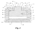
FIG. 4 , theseal assembly 11 is shown for aseal element 12 with a generally inverted T-shaped cross section. Theseal element 12 is disposed between the end rings 13, 14 so that thering 24 is bounded by the end rings 13, 14. Thering flange 25 is disposed between theflanges upper surfaces flanges - In some embodiments, it is preferred to include a
gap 44, disposed between one or bothflanges ring flange 25, to ensure that theseal element 12 floats inside theseal assembly 11 and has sufficient radial motion to properly adjust with thermal effects. In other embodiments, agap 44 could be disposed between adjacent vertical walls along thering 24 and oneend ring 13. In yet other embodiments, agap 31 could be disposed between thelower surface 30 along oneflange 18 and the firstouter surface 27 along thering 24. In still other embodiments, at least one firstouter surface 27 should contact thelower surface 29 along theflange 21, because of manufacturing tolerance variations along theouter surfaces 27 of thering 24 andlower surfaces 29 of theflanges gap 31 is present when components are precision machined so that theupper surfaces outer surface 27 of thering 24 are dimensionally identical. - In some embodiments, a
spacer ring 16 is provided between the end rings 13, 14 so as to contact the outer surface of theinner shaft 19. One ormore cavities 32 could traverse thespacer ring 16 about its circumference and one or both end rings 13, 14. Roll pins 35 andcavities 32 are complementary shaped so as to allow aroll pin 35 to be inserted into eachcavity 32. Eachcavity 32 along the end rings 13, 14 could be dimensioned to form an interference fit with aroll pin 35, while thecavity 32 through thespacer ring 16 could provide an interference or clearance fit. The roll pins 35 secure theseal element 12, end rings 13, 14, andspacer ring 16 so as to form a cartridge-like assembly. - In other embodiments, the
spacer ring 16 could be spaced apart from theseal element 12 via agap 17 of circular extent. Thegap 17 should have sufficient radial height to accommodate the relative radial motion of theseal element 12 about thecavity 33 because of the clearance fit of theanti-rotation pin 34. - In preferred embodiments, there is no relative movement between the
seal element 12 and other components comprising theseal assembly 11. One ormore cavities 33 could completely or partially traverse theseal element 12 about its circumference and one or both end rings 13, 14. Anti-rotation pins 34 andcavities 33 are shaped so as to allow ananti-rotation pin 34 to be inserted into eachcavity 33. - Each
anti-rotation pin 34 could be press fitted onto theend ring 14 by providing an interference fit between theanti-rotation pin 34 andcavity 33 along the thickness of theend ring 14. However, thecavity 33 portion through theseal element 12 should be larger than the diameter of theanti-rotation pin 34 so as to allow theseal element 12 to slide or move axially and radially in response to mechanical and thermal effects to avoid binding along theseal element 12. For example, thecavity 33 portion through theseal element 12 could be either circular or slot-shaped. If movement of theseal element 12 is overly restricted due to inadequate clearance between the diameter of thecavity 33 along theseal element 12 and the diameter ofanti-rotation pin 34 therein, the firstouter surface 27 along theseal element 12 will not follow and seat onto thelower surface 29 of theflange 21. The result could be an unsteady condition without uniform radial support along theseal element 12 by the flanges18, 21, potentially causing theseal element 12 to crack or explode. Other anti-rotation elements and approaches known within the art are applicable. - Each
end ring relief 37 disposed in a circumferential arrangement at the intersection of thehorizontal flange end ring seal element 12. Therelief 37 could be a radius, if space constraints preclude arelief 37. For example, a chamfer could be included at the interfaces of the firstouter surface 27 and the vertical face of thering 24. - Referring again to
FIGS. 2-4 , the left hand side of theseal assembly 11 is the high pressure side. When pressure is introduced, theseal element 12 seats onto the low pressure side of theend ring 14. The joint 41 includes a space which is compressed when theseal element 12 is assembled to form aseal assembly 11. Also, the firstouter surface 27 seats and seals onto thelower surface 29. If the tension along theseal element 12 is inadequate to radially seat the firstouter surface 27 againstlower surface 29, anexpander spring 48 could be used along the inner diameter of theseal element 12, as shown inFIGS. 9a and 9b . During operation of the inner andouter shafts seal element 12 as theinner shaft 19 rotates; however, the tension described herein is required along theseal element 12 in order to properly seat theseal element 12 when theinner shaft 19 is stationary. - By selecting materials with coefficient of thermal expansion rates which are sufficiently similar, it is possible for the end rings 13, 14,
spacer ring 16,inner shaft 19, andouter shaft 20 to expand and contract at similar rates. When thelower surface 29 expands, the firstouter surface 27 follows thelower surface 29 because of the centrifugal force produced by the rotatinginner shaft 19. The joint 41 opens to accommodate diametrical changes along thelower surface 29 caused by thermal effects, thus closely maintaining theclearance 40 shown inFIG. 2 between the outer diameter of theseal element 12 and inner diameter of theouter shaft 20. - Referring again to
FIGS. 2 ,4 and5 , thegap seal element gap 54 inFIG. 1a accommodates movement of theseal element 2 when inner andouter shafts cavity 33 within theseal element seal element cavity 33 within theseal element cavity 33 disposed along theend ring 14. Furthermore, theclearance 40 inFIG. 2 is well defined, since theouter shaft 20 should not contact theseal element seal element FIGS. 1a and1b . - Referring now to
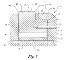
FIG. 5 , theseal assembly 11 fromFIG. 4 is shown having aseal element 38 with a generally L-shaped cross section composed of aring 24 andring flange 25. Theseal element 38 is disposed between a generally planar-shapedend ring 36 and an L-shapedend ring 14 so that thering 24 is bounded by both end rings 14, 36. Thering flange 25 is disposed between theend ring 36 and aflange 21 extending from thesecond end ring 14 so as to at least extend in a radial fashion beyond theupper surface 45 of theflange 21. - In some embodiments, it is preferred to include a
gap 44, disposed between the vertical sides offlange 21 and/or theend ring 36 and the vertical walls of thering flange 25, to ensure that theseal element 38 floats inside theseal assembly 11 and has sufficient radial motion to properly adjust to thermal effects. The firstouter surface 27 should contact thelower surface 29 along theflange 21. - In other embodiments, a
spacer ring 16 is provided between the end rings 14, 36 so as to contact the outer surface of theinner shaft 19. One ormore cavities 32 could traverse thespacer ring 16 about its circumference and one or both end rings 14, 36. Roll pins 35 andcavities 32 are complementary shaped so as to allow aroll pin 35 to be inserted into eachcavity 32. The roll pins 35 secure theseal element 38, end rings 14, 36, andspacer ring 16 so as to form a cartridge-like assembly, providing a structure which is readily shippable and handle-able. Eachcavity 32 along the end rings 14, 36 could provide an interference fit with theroll pin 35, while thecavity 32 along thespacer ring 16 could provide either an interference or clearance fit. - In yet other embodiments, the
spacer ring 16 could be separated from theseal element 38 via agap 22 of circular extent. Thegap 22 should have sufficient radial height to accommodate the relative radial motion of theseal element 38 about thecavity 33 because of the clearance fit of theanti-rotation pin 34. - In preferred embodiments, there is no relative movement between the
seal element 38 and other components comprising theseal assembly 11. One ormore cavities 33 could completely or partially traverse theseal element 38 about its circumference and one or both end rings 14, 36. Anti-rotation pins 34 andcavities 33 are shaped so as to allow ananti-rotation pin 34 to be inserted into eachcavity 33. However, other anti-rotation elements and approaches known within the art are likewise applicable to the embodiments described herein. - Each
anti-rotation pin 34 should be press fitted onto theend ring 14 by providing an interference fit betweenanti-rotation pin 34 andcavity 33 along the thickness of theend ring 14. However, thecavity 33 portion along theseal element 38 should be larger than the diameter of theanti-rotation pin 34 so as to allow theseal element 38 to slide or move axially and radially in response to mechanical and thermal effects without binding theseal element 12. For example, thecavity 33 along theseal element 38 could be either circular or slot-shaped. If movement of theseal element 38 is overly restricted due to inadequate clearance between the diameter of thecavity 33 along theseal element 12 and the diameter ofanti-rotation pin 34 therein, the firstouter surface 27 along theseal element 38 would not follow and seat onto thelower surface 29 of theflange 21, as described herein. - The
end ring 14 is preferred to include arelief 37 disposed in a circumferential arrangement at the intersection of thehorizontal flange 21 with the vertical structure of theend ring 14, so as to avoid stress concentrations therein and fit and wear problems with theseal element 38. Therelief 37 could include a radius depending on space constraints. - In some embodiments, it might be advantageous for seal and/or wear purposes to include a non-linear profile along the second
outer surface 28 of theseal elements FIGS. 4 and5 , respectively. - Referring now to
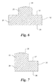
FIG. 6 , an inverted T-shapedseal element 12 is shown having a generally concave-shapedupper surface 39 along thering flange 25. Remaining features of thering 24, namely, firstouter surface 27 andinner surface 26 are as described herein. - Referring now to
FIG. 7 , an L-shapedseal element 38 is shown having a generally concave-shapedupper surface 39 along thering flange 25. Remaining features of thering 24, namely, firstouter surface 27 andinner surface 26 are as described herein. - Other contoured geometries composed of one or more concave, convex, and/or linear segments are likewise possible along the
upper surface 39. Theupper surface 39 could be molded onto or machined or shaped into an otherwise linear profile along the outermost diametrical surface of aseal element - In other embodiments, it might be advantageous for seal and/or wear purposes to include a
spring 48 along theseal elements FIGS. 4 and5 , respectively. For example,FIGS. 9a and 9b show aspring 48 disposed along agroove 49 about theinner diameter 52 of the inverted T-shapedseal element 12 and L-shapedseal element 38, respectively. Thespring 48 could be a garter spring, expander spring, or the like. Thegroove 49 is a semi-circular structure disposed along theseal element spring 48. Thespring 48 imparts a radial force to seat theouter surface 27 of theseal element lower surfaces 29 and/or 30 as theinner shaft 19 rotates. In other embodiments, thespring 48 could exert an outward radial force onto theseal element seal element - Referring now to
FIGS. 10 and11 , it might be advantageous to arrange two ormore seal assemblies 11, comprised of T-shapedseal elements 12 and/or L-shapedseal elements 38 described herein, in a stacked or serial fashion between aninner shaft 19 and anouter shaft 20.Seal assemblies 11 could be secured to theinner shaft 19 between amechanical stop 47 and alocking ring 5, however other arrangements are possible. The total number ofseal assemblies 11 is dependent on the space constraints along theinner shaft 19. InFIG. 10 , theseal assemblies 11 are constructed as described herein. InFIG. 11 , the innermost end rings 14, 13 identified inFIG. 10 are replaced by a singleintermediate ring 53 having a generally T-shaped cross section. Both multi-seal assemblies reduce the total flow of air across the seal system. - The
seal elements outer shafts clearance 40 represented inFIG. 2 . However, the invention described herein also allows for the use of high-temperature metal and metal alloys because theseal assembly 11 avoids the wear problems associated with dual-shaft systems. Exemplary metal and metal alloys could include, but are not limited to, 17-4 PH, 410 SS, titanium, and Inconel-X® (the registered trademark of the Huntington Alloys Corporation of Huntington, West Virginia). Metals further allow the matching of thermal expansion coefficients for materials composing the inner andouter shafts seal element - The description above indicates that a great degree of flexibility is offered in terms of the present invention. Although various embodiments have been described in considerable detail with reference to certain preferred versions thereof, other versions are possible. Therefore, the spirit and scope of the appended claims should not be limited to the description of the preferred versions contained herein.
- As is evident from the explanation above, the intershaft seal and variations thereof described herein minimize wear and heating problems common to intershaft seal systems. The invention is expected to be used within applications wherein a housing is provided with a plurality of interior sections having rotating parts passing there through, wherein one of the interior housing sections must be isolated from another by means of a seal system. One specific non-limiting example is a turbine engine.
Claims (18)
- A seal assembly for use between an inner shaft and an outer shaft rotatable about a common axis within a turbine engine comprising:(a) a pair of end rings, at least one said end ring having a flange disposed along and extending from one side of said end ring, said flange having an upper surface and a lower surface; and(b) a seal element comprised of a ring and a ring flange, said ring wider than said ring flange, said ring having an inner radial surface and an outer radial surface, said ring flange disposed along and extending from said outer radial surface, said outer radial surface contacting said lower surface along at least one said flange, said seal element disposed between said end rings so that a portion of said ring flange extends beyond said flange.
- The seal assembly of claim 1, wherein said seal element has an inverted and substantially T-shaped cross section.
- The seal assembly of claim 1, wherein said seal element has a substantially L-shaped cross section.
- The seal assembly of claim 1, wherein at least one said end ring has a substantially L-shaped cross section.
- The seal assembly of claim 1, wherein a gap is disposed between said lower surface of one said end ring and said outer radial surface of said seal element.
- The seal assembly of claim 1, wherein said ring flange does not contact said outer shaft.
- The seal assembly of claim 1, wherein said ring flange has a contoured surface adjacent to said outer shaft.
- The seal assembly of claim 1, wherein said seal element and at least one said end ring do not experience relative movement.
- The seal assembly of claim 1, further comprising:(c) a gap bounded by said end rings, said seal element, and said inner shaft.
- The seal assembly of claim 9, further comprising:(d) a spacer ring disposed between said gap and said inner shaft.
- The seal assembly of claim 10, wherein said spacer ring is secured mechanically to at least one said end ring.
- The seal assembly of claim 10, further comprising:(e) a locking nut contacting one said end ring to secure said seal assembly to said inner shaft.
- The seal assembly of claim 12, wherein said seal element is movable between said end rings.
- The seal assembly of claim 1, further comprising:(c) a locking nut contacting one said end ring to secure said seal assembly to said inner shaft.
- The seal assembly of claim 1, wherein said seal element is composed of a temperature resistant metal, a temperature resistant metal alloy, or carbon graphite.
- The seal assembly of claim 1, wherein said seal element has at least one joint traversing its cross section.
- The seal assembly of claim 1, wherein one said end ring is an integral part of said inner shaft.
- The seal assembly of claim 1, further comprising:(c) a spring disposed within a groove along said seal element, said spring imparting an outward radial force onto said seal element.
Applications Claiming Priority (3)
| Application Number | Priority Date | Filing Date | Title |
|---|---|---|---|
| US12/210,246 US8205891B2 (en) | 2008-09-15 | 2008-09-15 | Intershaft seal assembly |
| PCT/US2009/052328 WO2010030448A1 (en) | 2008-09-15 | 2009-07-31 | Intershaft seal system |
| EP09813411.7A EP2324209B1 (en) | 2008-09-15 | 2009-07-31 | Intershaft seal system |
Related Parent Applications (3)
| Application Number | Title | Priority Date | Filing Date |
|---|---|---|---|
| EP09813411.7A Division EP2324209B1 (en) | 2008-09-15 | 2009-07-31 | Intershaft seal system |
| EP09813411.7A Division-Into EP2324209B1 (en) | 2008-09-15 | 2009-07-31 | Intershaft seal system |
| EP09813411.7 Division | 2009-07-31 |
Publications (3)
| Publication Number | Publication Date |
|---|---|
| EP2341218A2 true EP2341218A2 (en) | 2011-07-06 |
| EP2341218A3 EP2341218A3 (en) | 2017-04-05 |
| EP2341218B1 EP2341218B1 (en) | 2018-11-28 |
Family
ID=42005420
Family Applications (2)
| Application Number | Title | Priority Date | Filing Date |
|---|---|---|---|
| EP11162887.1A Active EP2341218B1 (en) | 2008-09-15 | 2009-07-31 | Intershaft seal system for turbo machines |
| EP09813411.7A Active EP2324209B1 (en) | 2008-09-15 | 2009-07-31 | Intershaft seal system |
Family Applications After (1)
| Application Number | Title | Priority Date | Filing Date |
|---|---|---|---|
| EP09813411.7A Active EP2324209B1 (en) | 2008-09-15 | 2009-07-31 | Intershaft seal system |
Country Status (3)
| Country | Link |
|---|---|
| US (1) | US8205891B2 (en) |
| EP (2) | EP2341218B1 (en) |
| WO (1) | WO2010030448A1 (en) |
Cited By (4)
| Publication number | Priority date | Publication date | Assignee | Title |
|---|---|---|---|---|
| WO2013187995A1 (en) | 2012-06-11 | 2013-12-19 | United Technologies Corporation | Ring seal midplate |
| WO2013191843A1 (en) * | 2012-06-19 | 2013-12-27 | Stein Seal Company | Intershaft seal with centrifugal compensation |
| US8820752B2 (en) | 2008-09-15 | 2014-09-02 | Stein Seal Company | Intershaft seal with centrifugal compensation |
| US9004495B2 (en) | 2008-09-15 | 2015-04-14 | Stein Seal Company | Segmented intershaft seal assembly |
Families Citing this family (34)
| Publication number | Priority date | Publication date | Assignee | Title |
|---|---|---|---|---|
| WO2013191718A1 (en) * | 2012-06-19 | 2013-12-27 | Stein Seal Company | Segmented intershaft seal assembly |
| GB201013844D0 (en) | 2010-08-19 | 2010-09-29 | Rolls Royce Plc | Intershaft seal |
| US8408555B2 (en) * | 2010-09-16 | 2013-04-02 | Stein Seal Company | Intershaft seal system for minimizing pressure induced twist |
| US8459653B2 (en) * | 2010-11-05 | 2013-06-11 | General Electric Company | Seal assembly segment joints |
| US8864446B2 (en) * | 2011-05-23 | 2014-10-21 | Siemens Energy, Inc. | Wear pin gap closure detection system for gas turbine engine |
| DE102011104065A1 (en) * | 2011-06-11 | 2012-12-13 | Daimler Ag | Exhaust gas turbocharger for internal combustion engine of motor vehicle, has housing part and adjusting element, which is movably mounted in translatory and rotational manner for influencing flow of medium through exhaust gas turbocharger |
| US8939710B2 (en) * | 2011-08-24 | 2015-01-27 | United Technologies Corporation | Rotating turbomachine seal |
| FR2982801B1 (en) * | 2011-11-23 | 2014-09-12 | Snecma | AXIAL CLAMPING SYSTEM OF A CARBON SEAL, CORRESPONDING CLAMPING PART AND TURBOMACHINE COMPRISING SUCH A CLAMPING SYSTEM |
| FR2985764B1 (en) * | 2012-01-16 | 2014-02-28 | Snecma | COAXIAL INTER-TREE SEALING DEVICE OF A TURBOMACHINE |
| FR2985762B1 (en) * | 2012-01-16 | 2016-02-12 | Snecma | COAXIAL INTER-TREE SEALING DEVICE OF A TURBOMACHINE |
| GB201214472D0 (en) | 2012-08-14 | 2012-09-26 | Rolls Royce Plc | Intershaft seal |
| GB201214476D0 (en) | 2012-08-14 | 2012-09-26 | Rolls Royce Plc | Inshaft seal |
| US9382813B2 (en) * | 2012-12-04 | 2016-07-05 | General Electric Company | Turbomachine diaphragm ring with packing retainment apparatus |
| US9388743B2 (en) | 2012-12-18 | 2016-07-12 | Solar Turbines Incorporated | Sealing system for flanged joint |
| AU2013387845B2 (en) | 2013-04-24 | 2017-07-20 | Eagle Industry Co., Ltd. | Sliding part |
| US9869198B2 (en) | 2015-05-13 | 2018-01-16 | General Electric Company | Intershaft integrated seal and lock-nut |
| US10563530B2 (en) | 2015-10-12 | 2020-02-18 | General Electric Company | Intershaft seal with dual opposing carbon seal rings |
| US10520096B2 (en) * | 2015-11-02 | 2019-12-31 | Rolls-Royce Corporation | Intershaft seal assembly |
| EP3306387B1 (en) | 2015-11-16 | 2018-10-03 | Axis AB | An elastic gasket, the use thereof, and a system comprising the elastic gasket |
| US10215043B2 (en) | 2016-02-24 | 2019-02-26 | United Technologies Corporation | Method and device for piston seal anti-rotation |
| US9850770B2 (en) * | 2016-04-29 | 2017-12-26 | Stein Seal Company | Intershaft seal with asymmetric sealing ring |
| US10598035B2 (en) * | 2016-05-27 | 2020-03-24 | General Electric Company | Intershaft sealing systems for gas turbine engines and methods for assembling the same |
| US11193591B2 (en) * | 2017-08-03 | 2021-12-07 | Raytheon Technologies Corporation | Seal sacrificial wear indicator |
| US11118684B2 (en) * | 2018-02-28 | 2021-09-14 | Kaydon Ring & Seal, Inc. | Retainer device for circumferential shaft seals |
| CN112334690B (en) | 2018-08-01 | 2023-02-28 | 伊格尔工业股份有限公司 | Sliding assembly |
| EP3842673A4 (en) | 2018-08-24 | 2022-05-04 | Eagle Industry Co., Ltd. | Sliding member |
| JP7292811B2 (en) | 2018-11-30 | 2023-06-19 | イーグル工業株式会社 | sliding parts |
| WO2020130087A1 (en) | 2018-12-21 | 2020-06-25 | イーグル工業株式会社 | Sliding component |
| EP3926186A4 (en) | 2019-02-14 | 2022-11-16 | Eagle Industry Co., Ltd. | Sliding component |
| US11592111B2 (en) | 2019-06-25 | 2023-02-28 | Caterpillar Inc. | Torque resistant seal |
| JP7399966B2 (en) | 2019-07-26 | 2023-12-18 | イーグル工業株式会社 | sliding parts |
| US11525515B2 (en) | 2020-02-11 | 2022-12-13 | Raytheon Technologies Corporation | Radial seal segment joint |
| US11542819B2 (en) * | 2021-02-17 | 2023-01-03 | Pratt & Whitney Canada Corp. | Split ring seal for gas turbine engine rotor |
| US11506071B2 (en) * | 2021-03-02 | 2022-11-22 | Raytheon Technologies Corporation | Piston ring shuttle carrier |
Family Cites Families (30)
| Publication number | Priority date | Publication date | Assignee | Title |
|---|---|---|---|---|
| US3124502A (en) * | 1964-03-10 | Composite fibrous lubricant packing | ||
| GB190824936A (en) * | 1908-11-19 | 1909-11-18 | British Thomson Houston Co Ltd | Improvements in Packings for Elastic Fluid Turbine Shafts. |
| US4082296A (en) * | 1976-05-26 | 1978-04-04 | Stein Philip C | Seal for sealing between a rotating member and a housing |
| GB1565018A (en) | 1977-04-20 | 1980-04-16 | Rolls Royce | Gas turbine seals |
| GB2092242B (en) * | 1981-01-31 | 1984-12-19 | Rolls Royce | Non-contacting gas seal |
| GB2092243B (en) * | 1981-01-31 | 1984-12-05 | Rolls Royce | Non-contacting gas seal |
| DE3545281A1 (en) * | 1985-12-20 | 1987-07-02 | Mtu Muenchen Gmbh | MECHANICAL SEAL |
| FR2602847B1 (en) | 1986-07-28 | 1990-04-27 | Sealol E G G | SEALING SYSTEM FOR A ROTATING SHAFT IN A SUPPORT ELEMENT |
| FR2603947B1 (en) * | 1986-09-17 | 1990-11-30 | Snecma | DEVICE FOR HOLDING A SEAL ON A SHAFT END AND TURBOMACHINE COMPRISING SAME |
| US4754984A (en) * | 1987-01-02 | 1988-07-05 | The United States Of America As Represented By The Secretary Of The Navy | Dual-seal-ring shaft seal |
| US6036191A (en) * | 1991-01-16 | 2000-03-14 | Adwest Engineering Limited | Rotary valve seal assembly |
| GB2256682B (en) * | 1991-06-15 | 1995-04-26 | Rolls Royce Plc | A hydraulic seal and method of assembling the same |
| JP3040541B2 (en) | 1991-07-25 | 2000-05-15 | 松下電工株式会社 | Wiring equipment for floor |
| GB2264541A (en) | 1992-02-29 | 1993-09-01 | Rolls Royce Plc | Improved sealing ring for gas turbine engines |
| DE29510961U1 (en) * | 1995-07-06 | 1995-09-14 | Burgmann Dichtungswerk Feodor | Sealing arrangement |
| US6196790B1 (en) * | 1998-12-17 | 2001-03-06 | United Technologies Corporation | Seal assembly for an intershaft seal in a gas turbine engine |
| JP4273446B2 (en) | 2000-04-27 | 2009-06-03 | 株式会社建研 | PC building construction method applicable to narrow site |
| US6378873B1 (en) * | 2000-06-02 | 2002-04-30 | General Electric Company | Low flow fluid film seal for hydrogen cooled generators |
| US6431550B1 (en) * | 2000-09-25 | 2002-08-13 | General Electric Company | Hydrogen seal ring having seal at ring intersegment |
| US7055826B2 (en) * | 2001-08-02 | 2006-06-06 | Dunrite Manufacturing Co., Inc. | Seal and bearing assembly |
| JP3593082B2 (en) * | 2001-10-09 | 2004-11-24 | 三菱重工業株式会社 | Shaft seal mechanism and turbine |
| EP1571380A4 (en) * | 2002-11-13 | 2012-12-26 | Toshiba Kk | Motor generator |
| JP2004233338A (en) | 2003-01-08 | 2004-08-19 | Tdk Corp | Defect detection method of disc substrate, apparatus for the same, and method for manufacturing substrate for optical disc |
| GB2397353A (en) * | 2003-01-18 | 2004-07-21 | Rolls Royce Plc | A sealing arangement for a labyrinth seal for a shaft |
| US6887038B2 (en) * | 2003-09-02 | 2005-05-03 | General Electric Company | Methods and apparatus to facilitate sealing between rotating turbine shafts |
| JP3917993B2 (en) | 2004-08-10 | 2007-05-23 | 三菱重工業株式会社 | A shaft seal mechanism, a structure for attaching the shaft seal mechanism to a stator, and a turbine including these. |
| US7648143B2 (en) * | 2005-10-18 | 2010-01-19 | United Technologies Corporation | Tandem dual element intershaft carbon seal |
| KR20070059569A (en) | 2005-12-07 | 2007-06-12 | 주식회사 소디프신소재 | Anode active material for lithium secondary battery having coating layer of carbon and non-carbon material and preparation thereof |
| US20080252019A1 (en) * | 2005-12-25 | 2008-10-16 | Xiuming Yu | Oil sealing ring |
| US7549834B2 (en) * | 2006-06-19 | 2009-06-23 | General Electric Company | Actuation pressure control for adjustable seals in turbomachinery |
-
2008
- 2008-09-15 US US12/210,246 patent/US8205891B2/en active Active
-
2009
- 2009-07-31 EP EP11162887.1A patent/EP2341218B1/en active Active
- 2009-07-31 EP EP09813411.7A patent/EP2324209B1/en active Active
- 2009-07-31 WO PCT/US2009/052328 patent/WO2010030448A1/en active Application Filing
Cited By (6)
| Publication number | Priority date | Publication date | Assignee | Title |
|---|---|---|---|---|
| US8820752B2 (en) | 2008-09-15 | 2014-09-02 | Stein Seal Company | Intershaft seal with centrifugal compensation |
| US9004495B2 (en) | 2008-09-15 | 2015-04-14 | Stein Seal Company | Segmented intershaft seal assembly |
| WO2013187995A1 (en) | 2012-06-11 | 2013-12-19 | United Technologies Corporation | Ring seal midplate |
| EP2859257A4 (en) * | 2012-06-11 | 2015-09-09 | United Technologies Corp | Ring seal midplate |
| US9410556B2 (en) | 2012-06-11 | 2016-08-09 | United Technologies Corporation | Ring seal midplate |
| WO2013191843A1 (en) * | 2012-06-19 | 2013-12-27 | Stein Seal Company | Intershaft seal with centrifugal compensation |
Also Published As
| Publication number | Publication date |
|---|---|
| US8205891B2 (en) | 2012-06-26 |
| EP2341218A3 (en) | 2017-04-05 |
| EP2324209A4 (en) | 2013-05-29 |
| EP2341218B1 (en) | 2018-11-28 |
| WO2010030448A1 (en) | 2010-03-18 |
| EP2324209B1 (en) | 2019-08-07 |
| EP2324209A1 (en) | 2011-05-25 |
| US20100066027A1 (en) | 2010-03-18 |
Similar Documents
| Publication | Publication Date | Title |
|---|---|---|
| EP2341218B1 (en) | Intershaft seal system for turbo machines | |
| US9004495B2 (en) | Segmented intershaft seal assembly | |
| US9850770B2 (en) | Intershaft seal with asymmetric sealing ring | |
| US8100403B2 (en) | Hydrodynamic intershaft seal and assembly | |
| EP2381145B1 (en) | Distortion resistant face seal counterface system | |
| US8657573B2 (en) | Circumferential sealing arrangement | |
| EP2910823A1 (en) | Bellows seal | |
| US6293555B1 (en) | Secondary seal for non-contacting face seals | |
| JP5837595B2 (en) | Sealing device | |
| EP0821773B1 (en) | A non-contact shaft seal and method of reducing failure of such seals | |
| EP4098845A1 (en) | Improved circumferential seal assembly with adjustable seating forces | |
| US4948151A (en) | Rotary end face seal assembly | |
| US6131913A (en) | Anti-rotation and axial locking arrangement of a gas seal on its sleeve | |
| US11346448B2 (en) | Carbon seal assembly | |
| WO2013191718A1 (en) | Segmented intershaft seal assembly | |
| CN111971495B (en) | Metal seal assembly for sealing between rotating shaft and stationary frame | |
| RU2598966C1 (en) | End gas dynamic seal of turbomachine rotor support | |
| EP4303472A1 (en) | Seal arrangement | |
| CN112334689B (en) | Mechanical seal with high pressure high temperature auxiliary seal | |
| RU2174632C2 (en) | Circular seal | |
| JP2007255603A (en) | Crushing roller, roller bearing for crushing roller and method for assembling the same |
Legal Events
| Date | Code | Title | Description |
|---|---|---|---|
| PUAI | Public reference made under article 153(3) epc to a published international application that has entered the european phase |
Free format text: ORIGINAL CODE: 0009012 |
|
| 17P | Request for examination filed |
Effective date: 20110420 |
|
| AC | Divisional application: reference to earlier application |
Ref document number: 2324209 Country of ref document: EP Kind code of ref document: P |
|
| AK | Designated contracting states |
Kind code of ref document: A2 Designated state(s): AT BE BG CH CY CZ DE DK EE ES FI FR GB GR HR HU IE IS IT LI LT LU LV MC MK MT NL NO PL PT RO SE SI SK SM TR |
|
| AX | Request for extension of the european patent |
Extension state: AL BA RS |
|
| REG | Reference to a national code |
Ref country code: DE Ref legal event code: R079 Ref document number: 602009055972 Country of ref document: DE Free format text: PREVIOUS MAIN CLASS: F01D0025180000 Ipc: F01D0011000000 |
|
| PUAL | Search report despatched |
Free format text: ORIGINAL CODE: 0009013 |
|
| AK | Designated contracting states |
Kind code of ref document: A3 Designated state(s): AT BE BG CH CY CZ DE DK EE ES FI FR GB GR HR HU IE IS IT LI LT LU LV MC MK MT NL NO PL PT RO SE SI SK SM TR |
|
| AX | Request for extension of the european patent |
Extension state: AL BA RS |
|
| RIC1 | Information provided on ipc code assigned before grant |
Ipc: F16J 15/44 20060101ALI20170227BHEP Ipc: F01D 11/00 20060101AFI20170227BHEP |
|
| GRAP | Despatch of communication of intention to grant a patent |
Free format text: ORIGINAL CODE: EPIDOSNIGR1 |
|
| STAA | Information on the status of an ep patent application or granted ep patent |
Free format text: STATUS: GRANT OF PATENT IS INTENDED |
|
| INTG | Intention to grant announced |
Effective date: 20180618 |
|
| GRAS | Grant fee paid |
Free format text: ORIGINAL CODE: EPIDOSNIGR3 |
|
| GRAA | (expected) grant |
Free format text: ORIGINAL CODE: 0009210 |
|
| STAA | Information on the status of an ep patent application or granted ep patent |
Free format text: STATUS: THE PATENT HAS BEEN GRANTED |
|
| AC | Divisional application: reference to earlier application |
Ref document number: 2324209 Country of ref document: EP Kind code of ref document: P |
|
| AK | Designated contracting states |
Kind code of ref document: B1 Designated state(s): AT BE BG CH CY CZ DE DK EE ES FI FR GB GR HR HU IE IS IT LI LT LU LV MC MK MT NL NO PL PT RO SE SI SK SM TR |
|
| REG | Reference to a national code |
Ref country code: GB Ref legal event code: FG4D |
|
| REG | Reference to a national code |
Ref country code: CH Ref legal event code: EP |
|
| REG | Reference to a national code |
Ref country code: DE Ref legal event code: R096 Ref document number: 602009055972 Country of ref document: DE |
|
| REG | Reference to a national code |
Ref country code: AT Ref legal event code: REF Ref document number: 1070485 Country of ref document: AT Kind code of ref document: T Effective date: 20181215 |
|
| REG | Reference to a national code |
Ref country code: IE Ref legal event code: FG4D |
|
| REG | Reference to a national code |
Ref country code: NL Ref legal event code: MP Effective date: 20181128 |
|
| REG | Reference to a national code |
Ref country code: LT Ref legal event code: MG4D |
|
| REG | Reference to a national code |
Ref country code: AT Ref legal event code: MK05 Ref document number: 1070485 Country of ref document: AT Kind code of ref document: T Effective date: 20181128 |
|
| PG25 | Lapsed in a contracting state [announced via postgrant information from national office to epo] |
Ref country code: LV Free format text: LAPSE BECAUSE OF FAILURE TO SUBMIT A TRANSLATION OF THE DESCRIPTION OR TO PAY THE FEE WITHIN THE PRESCRIBED TIME-LIMIT Effective date: 20181128 Ref country code: AT Free format text: LAPSE BECAUSE OF FAILURE TO SUBMIT A TRANSLATION OF THE DESCRIPTION OR TO PAY THE FEE WITHIN THE PRESCRIBED TIME-LIMIT Effective date: 20181128 Ref country code: FI Free format text: LAPSE BECAUSE OF FAILURE TO SUBMIT A TRANSLATION OF THE DESCRIPTION OR TO PAY THE FEE WITHIN THE PRESCRIBED TIME-LIMIT Effective date: 20181128 Ref country code: IS Free format text: LAPSE BECAUSE OF FAILURE TO SUBMIT A TRANSLATION OF THE DESCRIPTION OR TO PAY THE FEE WITHIN THE PRESCRIBED TIME-LIMIT Effective date: 20190328 Ref country code: HR Free format text: LAPSE BECAUSE OF FAILURE TO SUBMIT A TRANSLATION OF THE DESCRIPTION OR TO PAY THE FEE WITHIN THE PRESCRIBED TIME-LIMIT Effective date: 20181128 Ref country code: NO Free format text: LAPSE BECAUSE OF FAILURE TO SUBMIT A TRANSLATION OF THE DESCRIPTION OR TO PAY THE FEE WITHIN THE PRESCRIBED TIME-LIMIT Effective date: 20190228 Ref country code: BG Free format text: LAPSE BECAUSE OF FAILURE TO SUBMIT A TRANSLATION OF THE DESCRIPTION OR TO PAY THE FEE WITHIN THE PRESCRIBED TIME-LIMIT Effective date: 20190228 Ref country code: LT Free format text: LAPSE BECAUSE OF FAILURE TO SUBMIT A TRANSLATION OF THE DESCRIPTION OR TO PAY THE FEE WITHIN THE PRESCRIBED TIME-LIMIT Effective date: 20181128 Ref country code: ES Free format text: LAPSE BECAUSE OF FAILURE TO SUBMIT A TRANSLATION OF THE DESCRIPTION OR TO PAY THE FEE WITHIN THE PRESCRIBED TIME-LIMIT Effective date: 20181128 |
|
| PG25 | Lapsed in a contracting state [announced via postgrant information from national office to epo] |
Ref country code: PT Free format text: LAPSE BECAUSE OF FAILURE TO SUBMIT A TRANSLATION OF THE DESCRIPTION OR TO PAY THE FEE WITHIN THE PRESCRIBED TIME-LIMIT Effective date: 20190328 Ref country code: GR Free format text: LAPSE BECAUSE OF FAILURE TO SUBMIT A TRANSLATION OF THE DESCRIPTION OR TO PAY THE FEE WITHIN THE PRESCRIBED TIME-LIMIT Effective date: 20190301 Ref country code: SE Free format text: LAPSE BECAUSE OF FAILURE TO SUBMIT A TRANSLATION OF THE DESCRIPTION OR TO PAY THE FEE WITHIN THE PRESCRIBED TIME-LIMIT Effective date: 20181128 |
|
| PG25 | Lapsed in a contracting state [announced via postgrant information from national office to epo] |
Ref country code: NL Free format text: LAPSE BECAUSE OF FAILURE TO SUBMIT A TRANSLATION OF THE DESCRIPTION OR TO PAY THE FEE WITHIN THE PRESCRIBED TIME-LIMIT Effective date: 20181128 |
|
| PG25 | Lapsed in a contracting state [announced via postgrant information from national office to epo] |
Ref country code: PL Free format text: LAPSE BECAUSE OF FAILURE TO SUBMIT A TRANSLATION OF THE DESCRIPTION OR TO PAY THE FEE WITHIN THE PRESCRIBED TIME-LIMIT Effective date: 20181128 Ref country code: CZ Free format text: LAPSE BECAUSE OF FAILURE TO SUBMIT A TRANSLATION OF THE DESCRIPTION OR TO PAY THE FEE WITHIN THE PRESCRIBED TIME-LIMIT Effective date: 20181128 Ref country code: IT Free format text: LAPSE BECAUSE OF FAILURE TO SUBMIT A TRANSLATION OF THE DESCRIPTION OR TO PAY THE FEE WITHIN THE PRESCRIBED TIME-LIMIT Effective date: 20181128 Ref country code: DK Free format text: LAPSE BECAUSE OF FAILURE TO SUBMIT A TRANSLATION OF THE DESCRIPTION OR TO PAY THE FEE WITHIN THE PRESCRIBED TIME-LIMIT Effective date: 20181128 |
|
| REG | Reference to a national code |
Ref country code: DE Ref legal event code: R097 Ref document number: 602009055972 Country of ref document: DE |
|
| PG25 | Lapsed in a contracting state [announced via postgrant information from national office to epo] |
Ref country code: RO Free format text: LAPSE BECAUSE OF FAILURE TO SUBMIT A TRANSLATION OF THE DESCRIPTION OR TO PAY THE FEE WITHIN THE PRESCRIBED TIME-LIMIT Effective date: 20181128 Ref country code: SK Free format text: LAPSE BECAUSE OF FAILURE TO SUBMIT A TRANSLATION OF THE DESCRIPTION OR TO PAY THE FEE WITHIN THE PRESCRIBED TIME-LIMIT Effective date: 20181128 Ref country code: EE Free format text: LAPSE BECAUSE OF FAILURE TO SUBMIT A TRANSLATION OF THE DESCRIPTION OR TO PAY THE FEE WITHIN THE PRESCRIBED TIME-LIMIT Effective date: 20181128 Ref country code: SM Free format text: LAPSE BECAUSE OF FAILURE TO SUBMIT A TRANSLATION OF THE DESCRIPTION OR TO PAY THE FEE WITHIN THE PRESCRIBED TIME-LIMIT Effective date: 20181128 |
|
| PLBE | No opposition filed within time limit |
Free format text: ORIGINAL CODE: 0009261 |
|
| STAA | Information on the status of an ep patent application or granted ep patent |
Free format text: STATUS: NO OPPOSITION FILED WITHIN TIME LIMIT |
|
| PG25 | Lapsed in a contracting state [announced via postgrant information from national office to epo] |
Ref country code: SI Free format text: LAPSE BECAUSE OF FAILURE TO SUBMIT A TRANSLATION OF THE DESCRIPTION OR TO PAY THE FEE WITHIN THE PRESCRIBED TIME-LIMIT Effective date: 20181128 |
|
| 26N | No opposition filed |
Effective date: 20190829 |
|
| PG25 | Lapsed in a contracting state [announced via postgrant information from national office to epo] |
Ref country code: MC Free format text: LAPSE BECAUSE OF FAILURE TO SUBMIT A TRANSLATION OF THE DESCRIPTION OR TO PAY THE FEE WITHIN THE PRESCRIBED TIME-LIMIT Effective date: 20181128 |
|
| REG | Reference to a national code |
Ref country code: CH Ref legal event code: PL |
|
| PG25 | Lapsed in a contracting state [announced via postgrant information from national office to epo] |
Ref country code: TR Free format text: LAPSE BECAUSE OF FAILURE TO SUBMIT A TRANSLATION OF THE DESCRIPTION OR TO PAY THE FEE WITHIN THE PRESCRIBED TIME-LIMIT Effective date: 20181128 |
|
| REG | Reference to a national code |
Ref country code: BE Ref legal event code: MM Effective date: 20190731 |
|
| PG25 | Lapsed in a contracting state [announced via postgrant information from national office to epo] |
Ref country code: CH Free format text: LAPSE BECAUSE OF NON-PAYMENT OF DUE FEES Effective date: 20190731 Ref country code: BE Free format text: LAPSE BECAUSE OF NON-PAYMENT OF DUE FEES Effective date: 20190731 Ref country code: LU Free format text: LAPSE BECAUSE OF NON-PAYMENT OF DUE FEES Effective date: 20190731 Ref country code: LI Free format text: LAPSE BECAUSE OF NON-PAYMENT OF DUE FEES Effective date: 20190731 |
|
| PG25 | Lapsed in a contracting state [announced via postgrant information from national office to epo] |
Ref country code: IE Free format text: LAPSE BECAUSE OF NON-PAYMENT OF DUE FEES Effective date: 20190731 |
|
| PGFP | Annual fee paid to national office [announced via postgrant information from national office to epo] |
Ref country code: FR Payment date: 20200731 Year of fee payment: 12 |
|
| PG25 | Lapsed in a contracting state [announced via postgrant information from national office to epo] |
Ref country code: CY Free format text: LAPSE BECAUSE OF FAILURE TO SUBMIT A TRANSLATION OF THE DESCRIPTION OR TO PAY THE FEE WITHIN THE PRESCRIBED TIME-LIMIT Effective date: 20181128 |
|
| PG25 | Lapsed in a contracting state [announced via postgrant information from national office to epo] |
Ref country code: HU Free format text: LAPSE BECAUSE OF FAILURE TO SUBMIT A TRANSLATION OF THE DESCRIPTION OR TO PAY THE FEE WITHIN THE PRESCRIBED TIME-LIMIT; INVALID AB INITIO Effective date: 20090731 Ref country code: MT Free format text: LAPSE BECAUSE OF FAILURE TO SUBMIT A TRANSLATION OF THE DESCRIPTION OR TO PAY THE FEE WITHIN THE PRESCRIBED TIME-LIMIT Effective date: 20181128 |
|
| PG25 | Lapsed in a contracting state [announced via postgrant information from national office to epo] |
Ref country code: FR Free format text: LAPSE BECAUSE OF NON-PAYMENT OF DUE FEES Effective date: 20210731 |
|
| PG25 | Lapsed in a contracting state [announced via postgrant information from national office to epo] |
Ref country code: MK Free format text: LAPSE BECAUSE OF FAILURE TO SUBMIT A TRANSLATION OF THE DESCRIPTION OR TO PAY THE FEE WITHIN THE PRESCRIBED TIME-LIMIT Effective date: 20181128 |
|
| PGFP | Annual fee paid to national office [announced via postgrant information from national office to epo] |
Ref country code: GB Payment date: 20230726 Year of fee payment: 15 |
|
| PGFP | Annual fee paid to national office [announced via postgrant information from national office to epo] |
Ref country code: DE Payment date: 20230727 Year of fee payment: 15 |