EP2340954A2 - Individual-powered dual CVT differential system with stabilizing device - Google Patents
Individual-powered dual CVT differential system with stabilizing device Download PDFInfo
- Publication number
- EP2340954A2 EP2340954A2 EP10197012A EP10197012A EP2340954A2 EP 2340954 A2 EP2340954 A2 EP 2340954A2 EP 10197012 A EP10197012 A EP 10197012A EP 10197012 A EP10197012 A EP 10197012A EP 2340954 A2 EP2340954 A2 EP 2340954A2
- Authority
- EP
- European Patent Office
- Prior art keywords
- continuous variable
- transmission
- variable transmission
- load
- constituted
- Prior art date
- Legal status (The legal status is an assumption and is not a legal conclusion. Google has not performed a legal analysis and makes no representation as to the accuracy of the status listed.)
- Granted
Links
Images



Classifications
-
- B—PERFORMING OPERATIONS; TRANSPORTING
- B60—VEHICLES IN GENERAL
- B60K—ARRANGEMENT OR MOUNTING OF PROPULSION UNITS OR OF TRANSMISSIONS IN VEHICLES; ARRANGEMENT OR MOUNTING OF PLURAL DIVERSE PRIME-MOVERS IN VEHICLES; AUXILIARY DRIVES FOR VEHICLES; INSTRUMENTATION OR DASHBOARDS FOR VEHICLES; ARRANGEMENTS IN CONNECTION WITH COOLING, AIR INTAKE, GAS EXHAUST OR FUEL SUPPLY OF PROPULSION UNITS IN VEHICLES
- B60K6/00—Arrangement or mounting of plural diverse prime-movers for mutual or common propulsion, e.g. hybrid propulsion systems comprising electric motors and internal combustion engines
- B60K6/20—Arrangement or mounting of plural diverse prime-movers for mutual or common propulsion, e.g. hybrid propulsion systems comprising electric motors and internal combustion engines the prime-movers consisting of electric motors and internal combustion engines, e.g. HEVs
- B60K6/50—Architecture of the driveline characterised by arrangement or kind of transmission units
- B60K6/52—Driving a plurality of drive axles, e.g. four-wheel drive
-
- B—PERFORMING OPERATIONS; TRANSPORTING
- B60—VEHICLES IN GENERAL
- B60K—ARRANGEMENT OR MOUNTING OF PROPULSION UNITS OR OF TRANSMISSIONS IN VEHICLES; ARRANGEMENT OR MOUNTING OF PLURAL DIVERSE PRIME-MOVERS IN VEHICLES; AUXILIARY DRIVES FOR VEHICLES; INSTRUMENTATION OR DASHBOARDS FOR VEHICLES; ARRANGEMENTS IN CONNECTION WITH COOLING, AIR INTAKE, GAS EXHAUST OR FUEL SUPPLY OF PROPULSION UNITS IN VEHICLES
- B60K6/00—Arrangement or mounting of plural diverse prime-movers for mutual or common propulsion, e.g. hybrid propulsion systems comprising electric motors and internal combustion engines
- B60K6/20—Arrangement or mounting of plural diverse prime-movers for mutual or common propulsion, e.g. hybrid propulsion systems comprising electric motors and internal combustion engines the prime-movers consisting of electric motors and internal combustion engines, e.g. HEVs
- B60K6/42—Arrangement or mounting of plural diverse prime-movers for mutual or common propulsion, e.g. hybrid propulsion systems comprising electric motors and internal combustion engines the prime-movers consisting of electric motors and internal combustion engines, e.g. HEVs characterised by the architecture of the hybrid electric vehicle
- B60K6/44—Series-parallel type
- B60K6/442—Series-parallel switching type
-
- B—PERFORMING OPERATIONS; TRANSPORTING
- B60—VEHICLES IN GENERAL
- B60K—ARRANGEMENT OR MOUNTING OF PROPULSION UNITS OR OF TRANSMISSIONS IN VEHICLES; ARRANGEMENT OR MOUNTING OF PLURAL DIVERSE PRIME-MOVERS IN VEHICLES; AUXILIARY DRIVES FOR VEHICLES; INSTRUMENTATION OR DASHBOARDS FOR VEHICLES; ARRANGEMENTS IN CONNECTION WITH COOLING, AIR INTAKE, GAS EXHAUST OR FUEL SUPPLY OF PROPULSION UNITS IN VEHICLES
- B60K6/00—Arrangement or mounting of plural diverse prime-movers for mutual or common propulsion, e.g. hybrid propulsion systems comprising electric motors and internal combustion engines
- B60K6/20—Arrangement or mounting of plural diverse prime-movers for mutual or common propulsion, e.g. hybrid propulsion systems comprising electric motors and internal combustion engines the prime-movers consisting of electric motors and internal combustion engines, e.g. HEVs
- B60K6/42—Arrangement or mounting of plural diverse prime-movers for mutual or common propulsion, e.g. hybrid propulsion systems comprising electric motors and internal combustion engines the prime-movers consisting of electric motors and internal combustion engines, e.g. HEVs characterised by the architecture of the hybrid electric vehicle
- B60K6/44—Series-parallel type
- B60K6/448—Electrical distribution type
-
- B—PERFORMING OPERATIONS; TRANSPORTING
- B60—VEHICLES IN GENERAL
- B60K—ARRANGEMENT OR MOUNTING OF PROPULSION UNITS OR OF TRANSMISSIONS IN VEHICLES; ARRANGEMENT OR MOUNTING OF PLURAL DIVERSE PRIME-MOVERS IN VEHICLES; AUXILIARY DRIVES FOR VEHICLES; INSTRUMENTATION OR DASHBOARDS FOR VEHICLES; ARRANGEMENTS IN CONNECTION WITH COOLING, AIR INTAKE, GAS EXHAUST OR FUEL SUPPLY OF PROPULSION UNITS IN VEHICLES
- B60K17/00—Arrangement or mounting of transmissions in vehicles
- B60K17/04—Arrangement or mounting of transmissions in vehicles characterised by arrangement, location or kind of gearing
- B60K17/043—Transmission unit disposed in on near the vehicle wheel, or between the differential gear unit and the wheel
-
- B—PERFORMING OPERATIONS; TRANSPORTING
- B60—VEHICLES IN GENERAL
- B60K—ARRANGEMENT OR MOUNTING OF PROPULSION UNITS OR OF TRANSMISSIONS IN VEHICLES; ARRANGEMENT OR MOUNTING OF PLURAL DIVERSE PRIME-MOVERS IN VEHICLES; AUXILIARY DRIVES FOR VEHICLES; INSTRUMENTATION OR DASHBOARDS FOR VEHICLES; ARRANGEMENTS IN CONNECTION WITH COOLING, AIR INTAKE, GAS EXHAUST OR FUEL SUPPLY OF PROPULSION UNITS IN VEHICLES
- B60K7/00—Disposition of motor in, or adjacent to, traction wheel
- B60K7/0007—Disposition of motor in, or adjacent to, traction wheel the motor being electric
-
- Y—GENERAL TAGGING OF NEW TECHNOLOGICAL DEVELOPMENTS; GENERAL TAGGING OF CROSS-SECTIONAL TECHNOLOGIES SPANNING OVER SEVERAL SECTIONS OF THE IPC; TECHNICAL SUBJECTS COVERED BY FORMER USPC CROSS-REFERENCE ART COLLECTIONS [XRACs] AND DIGESTS
- Y02—TECHNOLOGIES OR APPLICATIONS FOR MITIGATION OR ADAPTATION AGAINST CLIMATE CHANGE
- Y02T—CLIMATE CHANGE MITIGATION TECHNOLOGIES RELATED TO TRANSPORTATION
- Y02T10/00—Road transport of goods or passengers
- Y02T10/60—Other road transportation technologies with climate change mitigation effect
- Y02T10/62—Hybrid vehicles
Definitions
- the present invention relates to two or more than two independent motors installed at the common load, through speed ratio variation made by the CVT individually installed between the individual motor and the individual driven load, to match the differential speed operation drive between the loads driven by individual motor, in which the stabilizing device constituted by the torque limited coupling device with sliding damping during sliding is installed between the loads individually driven by the two CVTs, the stabilizing device synchronously operates when the torque transmitted between the two loads operates within the limited torque range, and the stabilizing device differentially operates to produce sliding damping to stabilize the operation of the drive system when the torque transmitted between the two loads exceeds the limited torque range.
- the differential speed function is often achieved by differential wheel group, which has shortcomings including transmission efficiency loss, space used, and weight; if a vehicle is driven by dual motors, two independent drive circuits are often installed, and the central control unit refers to the following parameters, such as vehicle speed, output rotational speed detection device, steeling wheel shift values, as well as the road gradient, the center of gravity in the vehicle after load, and processes for controlling the two independent drive circuits, and then the two independent drive circuits respectively drive the two motors to make close loop or semi-close loop rotational speed control between the two motors for achieving differential speed function, but it has shortcomings including high cost and complex system operation.
- the present invention relates to a multi-motor driving common load, such as two or more motors, in which the CVT is installed between individual motor and a wheel group at individual load, when the multi-motor with two or more than two motors installed at the common load structure individually drives the individual load through the arranged CVT to get rotational speed difference, and to make differential speed drive operation through the speed ratio variation by the CVT, and the stabilizing device constituted by the torque limited coupling device with sliding damping during sliding is installed between the loads individually driven by the two CVTs, during driving operation, if the loads individually driven by the two CVTs vary, or if the response time of the clutch unit at the loads individually driven by the two CVTs is slower, or if the two clutch units operate unstably because of the synchronous response time difference thereof, the stabilizing device installed between the loads operates to stabilize the system.
- the present invention relates to a multi-motor driving common load, such as two or more motors, in which the CVT is installed between individual motor and a wheel group at individual load, when the multi-motor with two or more than two motors installed at the common load structure individually drives the individual load through the arranged CVT to get rotational speed difference, and to make differential speed drive operation through the speed ratio variation by the CVT, and the stabilizing device constituted by the torque limited coupling device with sliding damping during sliding is installed between the loads individually driven by the two CVTs, during driving operation, if the loads individually driven by the two CVTs vary, or if the response time of the clutch unit at the loads individually driven by the two CVTs is slower, or if the two clutch units operate unstably because of the synchronous response time difference thereof, the stabilizing device installed between the loads operates to stabilize the system.
- the CVT in the present invention is a continuous variable transmission, which can automatically change the speed ratio with the load state, or change the speed ratio in receiving external manipulation, including a variety of types, such as rubber belt type, metal belt type, and chain type CVT, or the electronic continuous variable transmission (ECVT), or the friction disk type, or the conventional iso-axis continuous variable transmission.
- types such as rubber belt type, metal belt type, and chain type CVT, or the electronic continuous variable transmission (ECVT), or the friction disk type, or the conventional iso-axis continuous variable transmission.
- the common load in the present invention refers to the wheel-type vehicle, tracked vehicle, rail vehicle, or ship driven by at least two independent motors installed, or conveyor for stream of people or logistics, or industrial equipment driven by at least two motors; the common load may be further equipped with the engine power system, free wheel, and related operational interface unit.
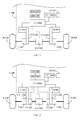
- Fig. 1 is a schematic view showing an embodiment of the individual-powered dual CVT differential system with stabilizing device.
- the structure is as following, in which, for the common load body L100, the motor M100 is installed to drive the wheel group W100 placed at the load through the continuous variable transmission CVT100 and the transmission T100, and the motor M200 is installed to drive the wheel group W200 placed at the load through the continuous variable transmission CVT200 and the transmission T200, and the stabilizing device constituted by the torque limited coupling device with sliding damping during sliding is installed between the loads individually driven by the two CVTs of the motors, if the wheel group W100 and the wheel group W200 placed at the load are driven with speed differential, the continuous variable transmission CVT100 and the continuous variable transmission CVT200 automatically regulate the speed ratio with the load variation to coordinate with rotation differential between the wheel group W100 and the wheel group W200 at the load, and the stabilizing device stabilizes the operation between the loads individually driven by the two CVTs, in which:
- the speed ratio is individually regulated with the load variation of the wheel group W100 and the wheel group W200 installed at the load, to facilitate the speed differential operation drive between the wheel group W100 and the second wheel group W200 installed at the load, and the stabilizing device SDT100 stabilizes the operation between the loads individually driven by the continuous variable transmission CVT100 and the continuous variable transmission CVT200.
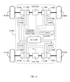
- Fig. 2 is a schematic view showing an embodiment of the individual-powered dual CVT differential system with stabilizing device in Fig. 1 to be additionally installed with clutch units.
- the clutch units CL100 and CL200 installed between the continuous variable transmission CVT100 and the transmission T100, and between the continuous variable transmission CVT200 and the transmission T200 are used to individually control the linking transmission or cutting separation between the continuous variable transmission CVT100 and the transmission T100, and between the continuous variable transmission CVT200 and the transmission T200;
- two or more than two sets of the individual-powered dual CVT differential systems with stabilizing device are further applied to the four- or more-wheel drive system.
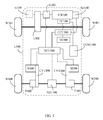
- Fig. 3 is a schematic view showing an embodiment of two sets of the individual-powered dual CVT differential systems with stabilizing device in Fig. 1 to be installed at a four-wheel drive common load body L200.
- the main components include:
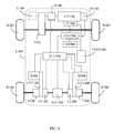
- Fig. 4 is a schematic view showing an embodiment of the system in Fig. 3 to be additionally installed with clutch units.
- the clutch units CL100 and CL200 installed between the continuous variable transmission CVT100 and the transmission T100, and between the continuous variable transmission CVT200 and the transmission T200, are used to individually control the linking transmission or cutting separation between the continuous variable transmission CVT100 and the transmission T100, and between the continuous variable transmission CVT200 and the transmission T200.
- the clutch units CL300 and CL400 installed between the continuous variable transmission CVT300 and the transmission T300, and between the continuous variable transmission CVT400 and the transmission T400, are used to individually control the linking transmission or cutting separation between the continuous variable transmission CVT300 and the transmission T300, and between the continuous variable transmission CVT400 and the transmission T400;
- the individual-powered dual CVT differential system with stabilizing device is further applied to the hybrid power drive system.
- Fig. 5 is a schematic view showing an embodiment that the multi-motor drive system with speed differential regulated by the continuous variable transmission and the engine power drive unit are simultaneously installed at a common load body L300 to form a hybrid power system.
- the main components include:
- the electric control unit ECU300 includes the drive control circuit of the continuous variable transmission with the user interface MI300 for accepting manual manipulation and/or controlled by the central control unit CCU300;
- the continuous variable transmission CVT100 and the continuous variable transmission CVT200 individually perform speed ratio regulation according to the load variation of the wheel group W100 and the wheel group W200 installed at the load, to facilitate the speed differential operation drive between the wheel group W100 and the second wheel group W200 installed at the load.
- the system is also installed with the required fuel control unit FC100, the tank TANK 100, and/or the engine speed detecting device SD100 for the control of the engine drive operation, including:
- the hybrid power system constituted by the individual-powered dual CVT differential system with stabilizing device, as shown in Fig. 5 includes one or more of the following operational functions, including:
- the multi-motor drive system with speed differential regulated by the continuous variable transmission and the engine power drive unit are simultaneously installed at the common load body L300 to constitute the hybrid power system, in which, for the multi-motor drive system with speed differential regulated by the continuous variable transmission installed at the common load body L300, the load is directly driven by the continuous variable transmission, or driven by the continuous variable transmission and the transmission, furthermore, the clutch unit CL100 is additionally installed between the continuous variable transmission CVT100 and the transmission T100, and the clutch unit CL200 is additionally installed between the continuous variable transmission CVT200 and the transmission T200, to individually control the linking transmission or cutting separation between the continuous variable transmission CVT100 and the transmission T100, and between the continuous variable transmission CVT200 and the transmission T200.
- Fig. 6 is a schematic view showing an embodiment of the system in Fig. 5 to be additionally installed with clutch units;
- the hybrid power system constituted by the individual-powered dual CVT differential system with stabilizing device and the engine power system is further additionally installed with an electric storage-discharge unit ESD100 to improve the function.
- Fig. 7 is a schematic view showing an embodiment that the multi-motor drive systems with speed differential regulated by continuous variable transmission, the engine power drive unit, and the electric storage-discharge unit ESD100 are simultaneously installed at a common load body L400 to form a hybrid power system.
- the electric storage-discharge unit ESD100 is used to receive the generating power of the generator G100 driven by the engine ICE100 for charging, and/or to receive the power of the regenerated electricity from kinetic energy reclaimed by the motor M100 and/or the motor M200 for charging, and/or to receive the external power supply for charging, by way of the power provided by the electric storage-discharge unit ESD 100 and/or the power generated by the generator G 100, through the motor drive control circuit in the electric control unit ECU400, to control the driving operations of the motor M100 and the motor M200, the components including:
- the continuous variable transmission CVT100 and the continuous variable transmission CVT200 individually perform speed ratio regulation according to the load variation of the wheel group W100 and the wheel group W200 installed at the load, to facilitate the speed differential operation drive between the wheel group W100 and the wheel group W200 installed at the load.
- the system is also installed with the required fuel control unit FC100, the tank TANK 100, and/or the engine speed detecting device SD100 for the control of the engine drive operation, including:
- the hybrid power system installed with the electric storage-discharge unit ESD100, as shown in Fig. 7 includes one or more of the following operational functions, including:
- the multi-motor drive system with speed differential regulated by the continuous variable transmission and the engine power drive unit as shown in Fig. 7 the multi-motor drive system with speed differential regulated by the continuous variable transmission installed at the common load body L400, except for directly drives, the load by the continuous variable transmission, or drives the load by the continuous variable transmission and the transmission, furthermore, the clutch unit CL100 is additionally installed between the continuous variable transmission CVT100 and the transmission T100, and the clutch unit CL200 is additionally installed between the continuous variable transmission CVT200 and the transmission T200, to individually control the linking transmission or cutting separation between the continuous variable transmission CVT100 and the transmission T100, and between the continuous variable transmission CVT200 and the transmission T200.
- Fig. 8 is a schematic view showing an embodiment of the system in Fig. 7 to be additionally installed with clutch units;
Landscapes
- Engineering & Computer Science (AREA)
- Chemical & Material Sciences (AREA)
- Combustion & Propulsion (AREA)
- Transportation (AREA)
- Mechanical Engineering (AREA)
- Hybrid Electric Vehicles (AREA)
- Electric Propulsion And Braking For Vehicles (AREA)
- Arrangement Of Transmissions (AREA)
- Control Of Vehicle Engines Or Engines For Specific Uses (AREA)
- Arrangement And Mounting Of Devices That Control Transmission Of Motive Force (AREA)
- Arrangement Or Mounting Of Propulsion Units For Vehicles (AREA)
- Motor Power Transmission Devices (AREA)
Abstract
Description
- The present invention relates to two or more than two independent motors installed at the common load, through speed ratio variation made by the CVT individually installed between the individual motor and the individual driven load, to match the differential speed operation drive between the loads driven by individual motor, in which the stabilizing device constituted by the torque limited coupling device with sliding damping during sliding is installed between the loads individually driven by the two CVTs, the stabilizing device synchronously operates when the torque transmitted between the two loads operates within the limited torque range, and the stabilizing device differentially operates to produce sliding damping to stabilize the operation of the drive system when the torque transmitted between the two loads exceeds the limited torque range.
- Traditionally, when two or more loads installed at the common load are driven through differential speed regulation by a single motor, the differential speed function is often achieved by differential wheel group, which has shortcomings including transmission efficiency loss, space used, and weight; if a vehicle is driven by dual motors, two independent drive circuits are often installed, and the central control unit refers to the following parameters, such as vehicle speed, output rotational speed detection device, steeling wheel shift values, as well as the road gradient, the center of gravity in the vehicle after load, and processes for controlling the two independent drive circuits, and then the two independent drive circuits respectively drive the two motors to make close loop or semi-close loop rotational speed control between the two motors for achieving differential speed function, but it has shortcomings including high cost and complex system operation.
- The present invention relates to a multi-motor driving common load, such as two or more motors, in which the CVT is installed between individual motor and a wheel group at individual load, when the multi-motor with two or more than two motors installed at the common load structure individually drives the individual load through the arranged CVT to get rotational speed difference, and to make differential speed drive operation through the speed ratio variation by the CVT, and the stabilizing device constituted by the torque limited coupling device with sliding damping during sliding is installed between the loads individually driven by the two CVTs, during driving operation, if the loads individually driven by the two CVTs vary, or if the response time of the clutch unit at the loads individually driven by the two CVTs is slower, or if the two clutch units operate unstably because of the synchronous response time difference thereof, the stabilizing device installed between the loads operates to stabilize the system.
-
-
Fig. 1 is a schematic view showing an embodiment of the individual-powered dual CVT differential system with stabilizing device; -
Fig. 2 is a schematic view showing an embodiment of the individual-powered dual CVT differential system with stabilizing device inFig. 1 to be additionally installed with clutch units; -
Fig. 3 is a schematic view showing an embodiment of two sets of the individual-powered dual CVT differential systems with stabilizing device inFig. 1 to be installed at a four-wheel drive common load body L200; -
Fig. 4 is a schematic view showing an embodiment of the system inFig. 3 to be additionally installed with clutch units; -
Fig. 5 is a schematic view showing an embodiment that the multi-motor drive system with speed differential regulated by the continuous variable transmission and the engine power drive unit are simultaneously installed at a common load body L300 to form a hybrid power system; -
Fig. 6 is a schematic view showing an embodiment of the system inFig. 5 to be additionally installed with a clutch unit; -
Fig. 7 is a schematic view showing an embodiment that the multi-motor drive systems with speed differential regulated by continuous variable transmission, the engine power drive unit, and the electric storage-discharge unit ESD100 are simultaneously installed at a common load body L400 to form a hybrid power system; and -
Fig. 8 is a schematic view showing an embodiment of the system inFig. 7 to be additionally installed with clutch units. -
- CCU100, CCU200, CCU300, CCU400: Central control unit
- CL100, CL200, CL300, CL400: Clutch unit
- CVT100, CVT200, CVT300, CVT400: Continuous variable transmission
- ECU100, ECU200, ECU300, ECU400: Electric control unit
- EMU 100: Electric energy management unit
- ESD 100: Electric storage-discharge unit
- FC 100: Fuel control unit
- G100: Generator
- ICE100: Engine
- L100, L200, L300, L400: Common load body
- M100, M200, M300, M400: Motor
- MI100, MI200, MI300, MI400: User interface
- SD100: Engine speed detecting device
- SDT100, SDT200: Stabilizing device
- T100, T200, T300, T301, T400: Transmission
- TANK100: Tank
- W100, W200, W300, W301, W400, W401: Wheel group
- The present invention relates to a multi-motor driving common load, such as two or more motors, in which the CVT is installed between individual motor and a wheel group at individual load, when the multi-motor with two or more than two motors installed at the common load structure individually drives the individual load through the arranged CVT to get rotational speed difference, and to make differential speed drive operation through the speed ratio variation by the CVT, and the stabilizing device constituted by the torque limited coupling device with sliding damping during sliding is installed between the loads individually driven by the two CVTs, during driving operation, if the loads individually driven by the two CVTs vary, or if the response time of the clutch unit at the loads individually driven by the two CVTs is slower, or if the two clutch units operate unstably because of the synchronous response time difference thereof, the stabilizing device installed between the loads operates to stabilize the system.
- The CVT in the present invention is a continuous variable transmission, which can automatically change the speed ratio with the load state, or change the speed ratio in receiving external manipulation, including a variety of types, such as rubber belt type, metal belt type, and chain type CVT, or the electronic continuous variable transmission (ECVT), or the friction disk type, or the conventional iso-axis continuous variable transmission.
- The common load in the present invention refers to the wheel-type vehicle, tracked vehicle, rail vehicle, or ship driven by at least two independent motors installed, or conveyor for stream of people or logistics, or industrial equipment driven by at least two motors; the common load may be further equipped with the engine power system, free wheel, and related operational interface unit.
- The various embodiments of the present invention are described as following.
-
Fig. 1 is a schematic view showing an embodiment of the individual-powered dual CVT differential system with stabilizing device. - As shown in
Fig. 1 , the structure is as following, in which, for the common load body L100, the motor M100 is installed to drive the wheel group W100 placed at the load through the continuous variable transmission CVT100 and the transmission T100, and the motor M200 is installed to drive the wheel group W200 placed at the load through the continuous variable transmission CVT200 and the transmission T200, and the stabilizing device constituted by the torque limited coupling device with sliding damping during sliding is installed between the loads individually driven by the two CVTs of the motors, if the wheel group W100 and the wheel group W200 placed at the load are driven with speed differential, the continuous variable transmission CVT100 and the continuous variable transmission CVT200 automatically regulate the speed ratio with the load variation to coordinate with rotation differential between the wheel group W100 and the wheel group W200 at the load, and the stabilizing device stabilizes the operation between the loads individually driven by the two CVTs, in which: - -- motors M100, M200: constituted by rotary motors, which are AC or DC, brushless or brush, synchronous or non-synchronous, internal or external rotation type;
- -- continuous variable transmissions CVT100, CVT200: related to continuous variable transmissions, which can automatically change the speed ratio according to the load state, or change the speed ratio in receiving external manipulation, including a variety of types, such as rubber belt type, metal belt type, and chain type CVT, or the electronic continuous variable transmission (ECVT), or the friction disk type, or the conventional iso-axis continuous variable transmission;
- -- stabilizing device SDT100: constituted by dual-end shaft coupling device with the functions of setting coupling torque and sliding damping when exceeding the torque, including the stabilizing device with dual-end shaft structure formed by fluid viscosity effect, fluid damping effect, mechanical friction effect, or electromagnetic eddy current effect or power generation anti-torque effect, in which the two revolution ends individually link between the loads of the continuous variable transmissions CVT100 and CVT200, if unstable operation is caused by the varied load at individual load side during driving operation, the stabilizing device SDT100 installed between the loads operates to stabilize the system;
- -- transmission T100: related to fixed speed ratio, variable speed ratio, or stepless speed variable transmission, which is constituted by mechanical gear unit, sprocket unit, pulley unit, or linkage group; and the transmission is selectable as needed;
- -- electric control unit ECU100: constituted by the electric machine and/or the solid state power element, and/or the electronic element, and/or the microprocessor, and/or related software, for receiving the control of the user interface MI100 and/or the central control unit CCU100, wherein a motor drive control circuit is installed within the electric control unit ECU100 for manipulating rotational speed, torque, rotary direction, and current of the parallel connected motors M100 and M200; or motor drive control circuits individually equipped to the motors M100 and M200 are individually installed within the electric control unit ECU100 for individually manipulating rotational speed, torque, rotary direction, and current of the motors M100 and M200, which do not involve the close loop or semi- close loop rotational speed control between the two motors to achieve the speed differential function; the speed differential operation between the loads is through the continuous variable transmission installed between the individual motor and the load to perform speed difference regulation;
if the continuous variable transmission which changes the speed ratio by receiving external manipulation is adopted by the system, the electric control unit ECU100 includes the drive control circuit of the continuous variable transmission with the user interface MI100 for accepting manual manipulation and/or controlled by the central control unit CCU100; - -- electric energy management unit EMU100: constituted by the electric machine, and/or solid state power element, and/or electronic element, and/or microprocessor, and/or related software, for controlling the output voltage, the current and the charging voltage and current of the electric storage-discharge unit ESD100, to start and stop the timing of charging;
- -- central control unit CCU100: related to analog or digital, or both mixed control device, constituted by the electric machine and/or solid state power element, and/or including microprocessor, and/or control software, and/or related circuit element, for following the command of the user interface MI100, and/or for setting control mode to further control the operation of the system;
- -- user interface MI100: related to linear analog or digital, or both mixed control device, constituted by the operating mechanism, and/or the electric machine, and/or the solid state circuit, for linking with the central control unit CCU100 to control the operation of the system;
- -- electric storage-discharge unit ESD 100: constituted by various rechargeable secondary battery, or capacitor, or super capacitor.
- Through the operation of the above device, if the common load body L100 is driven for operation, and the wheel group W100 and the wheel group W200 at the loads operate at differential speed, , the speed ratio is individually regulated with the load variation of the wheel group W100 and the wheel group W200 installed at the load, to facilitate the speed differential operation drive between the wheel group W100 and the second wheel group W200 installed at the load, and the stabilizing device SDT100 stabilizes the operation between the loads individually driven by the continuous variable transmission CVT100 and the continuous variable transmission CVT200.
- In addition, for the embodiment shown in
Fig. 1 , except for directly driving the load through CVT, or driving the load through CVT and the transmission, furthermore, the clutch unit CL100 is additionally installed between the continuous variable transmission CVT100 and the transmission T100, and the clutch unit CL200 is additionally installed between the continuous variable transmission CVT200 and the transmission T200.Fig. 2 is a schematic view showing an embodiment of the individual-powered dual CVT differential system with stabilizing device inFig. 1 to be additionally installed with clutch units. - The clutch units CL100 and CL200 installed between the continuous variable transmission CVT100 and the transmission T100, and between the continuous variable transmission CVT200 and the transmission T200 are used to individually control the linking transmission or cutting separation between the continuous variable transmission CVT100 and the transmission T100, and between the continuous variable transmission CVT200 and the transmission T200;
- As shown in
Fig. 2 , in which: - -- clutch units CL100, CL200: related to the clutch device or structure with the function of linking transmission or cutting separation, which is driven by manpower, and/or electricity, and/or magnetic power, and/or machine power, and/or gas pressure, and/or liquid pressure, and/or centrifugal force, and which has the rotary input side and the rotary output side;
- -- stabilizing device SDT100: constituted by dual-end shaft coupling device with the functions of setting coupling torque and sliding damping when exceeding the torque, including the stabilizing device with dual-end shaft structure formed by fluid viscosity effect, fluid damping effect, mechanical friction effect, or electromagnetic eddy current effect or power generation anti-torque effect, in which the two revolution ends individually link between two loads of the clutch units CL100 and CL200 individually driven by the continuous variable transmissions CVT100 and CVT200, during driving operation, if the load at individual load side varies, or if the response time of the clutch units CL100 and CL200 at the loads individually driven by the continuous variable transmissions CVT100 and CVT200 is slower, or if the clutch units CL100 and CL200 operate unstably because of the synchronous response time difference thereof, the stabilizing device SDT100 installed between the loads of the clutch units CL100 and CL200 operates to stabilize the system;
- For the individual-powered dual CVT differential system with stabilizing device, two or more than two sets of the individual-powered dual CVT differential systems with stabilizing device are further applied to the four- or more-wheel drive system.
-
Fig. 3 is a schematic view showing an embodiment of two sets of the individual-powered dual CVT differential systems with stabilizing device inFig. 1 to be installed at a four-wheel drive common load body L200. - As shown in
Fig. 3 , the main components include: - -- common load body L200: the common load body L200 is installed with two sets of the individual-powered dual CVT differential systems with stabilizing device, in which the first set of the individual-powered dual CVT differential system with stabilizing device is installed at the front end of the common load body L200, and the second set of the individual-powered dual CVT differential system with stabilizing device is installed at the rear end of the common load body L200, wherein:
the first set of the individual-powered dual CVT differential system with stabilizing device includes: - -- motors M100, M200: constituted by rotary motors, which are AC or DC, brushless or brush, synchronous or non-synchronous, internal or external rotation type;
- -- continuous variable transmissions CVT100, CVT200: related to continuous variable transmissions, which can automatically change the speed ratio according to the load state, or change the speed ratio in receiving external manipulation, including a variety of types, such as rubber belt type, metal belt type, and chain type CVT, or the electronic continuous variable transmission (ECVT), or the friction disk type, or the conventional iso-axis continuous variable transmission; and
- -- stabilizing device SDT100: constituted by dual-end shaft coupling device with the functions of setting coupling torque and sliding damping when exceeding the torque, including the stabilizing device with dual-end shaft structure formed by fluid viscosity effect, fluid damping effect, mechanical friction effect, or electromagnetic eddy current effect or power generation anti-torque effect, in which the two revolution ends individually link between the loads of the continuous variable transmissions CVT100 and CVT200, if unstable operation is caused by the varied load at individual load side during driving operation, the stabilizing device SDT100 installed between the loads operates to stabilize the system;
- -- transmissions T100, T200: related to fixed speed ratio, variable speed ratio, or stepless speed variable transmissions, which are constituted by mechanical gear units, sprocket units, pulley units, or linkage groups; and the transmissions are selectable as needed;
the second set of the individual-powered dual CVT differential system with stabilizing device includes: - -- motors M300, M400: constituted by rotary motors, which are AC or DC, brushless or brush, synchronous or non-synchronous, internal or external rotation type;
- -- continuous variable transmissions CVT300, CVT400: related to continuous variable transmissions, which can automatically change the speed ratio according to the load state, or change the speed ratio in receiving external manipulation, including a variety of types, such as rubber belt type, metal belt type, and chain type CVT, or the electronic continuous variable transmission (ECVT), or the friction disk type, or the conventional iso-axis continuous variable transmission; and
- -- stabilizing device SDT200: constituted by dual-end shaft coupling device with the functions of setting coupling torque and sliding damping when exceeding the torque, including the stabilizing device with dual-end shaft structure formed by fluid viscosity effect, fluid damping effect, mechanical friction effect, or electromagnetic eddy current effect or power generation anti-torque effect, in which the two revolution ends individually link between the loads of the continuous variable transmissions CVT300 and CVT400, if unstable operation is caused by the varied load at individual load side during driving operation, the stabilizing device SDT200 installed between the loads operates to stabilize the system;
- -- transmissions T300, T400: related to fixed speed ratio, variable speed ratio, or stepless speed variable transmissions, which are constituted by mechanical gear units, sprocket units, pulley units, or linkage groups;
- -- electric control unit ECU200: constituted by electric machine and/or solid state power element, and/or electronic element, and/or microprocessor, and/or related software, for receiving the control of the user interface MI200 and/or the central control unit CCU200, wherein a motor drive control circuit is installed within the electric control unit ECU200 for manipulating rotational speed, torque, rotary direction, and current of the parallel connected motors M100 and M200, and M300 and M400; or two motor drive control circuits are installed within the electric control unit ECU200, in which one motor drive control circuit is used to control the parallel connected motors M100 and M200, including controlling the rotational speed, torque, rotary direction, and current of the motors M100 and M200, and the other motor drive control circuit is used to control the parallel connected motors M300 and M400, including controlling the rotational speed, torque, rotary direction, and current of the motors M300 and M400; or motor drive control circuits are individually arranged for motors M100, M200, M300, and M400 individually installed within the electric control unit ECU200, for individually manipulating rotational speed, torque, rotary direction, and current of the motors M100, M200, M300, and M400, which do not involve the close loop or semi- close loop rotational speed control between the two motors to achieve the speed differential function; the speed differential operation between the loads is through the continuous variable transmission installed between the individual motor and the load to perform speed difference regulation;
if the continuous variable transmission which changes the speed ratio by receiving external manipulation is adopted by the system, the electric control unit ECU200 includes the drive control circuit of the continuous variable transmission with the user interface MI200 for accepting manual manipulation and/or controlled by the central control unit CCU200; - -- electric energy management unit EMU100: constituted by the electric machine, and/or solid state power element, and/or electronic element, and/or microprocessor, and/or related software, for controlling the output voltage, the current and the charging voltage and current of the electric storage-discharge unit ESD100, to start and stop the timing of charging;
- -- central control unit CCU200: related to analog or digital, or both mixed control device, constituted by the electric machine and/or solid state power element, and/or including microprocessor, and/or control software, and/or related circuit element, for following the command of the user interface MI200, and/or for setting control mode and further controlling the operation of the system;
- -- user interface MI200: related to linear analog or digital, or both mixed control device, constituted by the operating mechanism, and/or the electric machine, and/or the solid state circuit, for linking with the central control unit CCU200 to control the operations of the first set of the individual-powered dual CVT differential system with stabilizing device, and the second set of the individual-powered dual CVT differential system with stabilizing device in turn; and
- -- electric storage-discharge unit ESD100: constituted by various rechargeable secondary battery, or capacitor, or super capacitor.
- In addition, for the embodiment shown in
Fig. 3 , except for directly driving the load through CVT, or driving the load through CVT and the transmission, furthermore, the clutch unit CL100 is additionally installed between the continuous variable transmission CVT100 and the transmission T100, and the clutch unit CL200 is additionally installed between the continuous variable transmission CVT200 and the transmission T200, and for the second set of the individual-powered dual CVT differential system with stabilizing device, the clutch unit CL300 is additionally installed between the continuous variable transmission CVT300 and the transmission T300, and the clutch unit CL400 is additionally installed between the continuous variable transmission CVT400 and the transmission T400.Fig. 4 is a schematic view showing an embodiment of the system inFig. 3 to be additionally installed with clutch units. - The clutch units CL100 and CL200 installed between the continuous variable transmission CVT100 and the transmission T100, and between the continuous variable transmission CVT200 and the transmission T200, are used to individually control the linking transmission or cutting separation between the continuous variable transmission CVT100 and the transmission T100, and between the continuous variable transmission CVT200 and the transmission T200.
- The clutch units CL300 and CL400 installed between the continuous variable transmission CVT300 and the transmission T300, and between the continuous variable transmission CVT400 and the transmission T400, are used to individually control the linking transmission or cutting separation between the continuous variable transmission CVT300 and the transmission T300, and between the continuous variable transmission CVT400 and the transmission T400;
- As shown in
Fig. 4 , in which: - -- clutch units CL100, CL200, CL300, CL400: related to the clutch device or structure with the function of linking transmission or cutting separation, which is driven by manpower, and/or electricity, and/or magnetic power, and/or machine power, and/or gas pressure, and/or liquid pressure, and/or centrifugal force, and which has the rotary input side and the rotary output side.
- -- stabilizing device SDT100: constituted by dual-end shaft coupling device with the functions of setting coupling torque and sliding damping when exceeding the torque, including the stabilizing device with dual-end shaft structure formed by fluid viscosity effect, fluid damping effect, mechanical friction effect, or electromagnetic eddy current effect or power generation anti-torque effect, in which the two revolution ends individually link between two loads of the clutch units CL100 and CL200 individually driven by the continuous variable transmissions CVT100 and CVT200, during driving operation, if the load at individual load side varies, or if the response time of the clutch units CL100 and CL200 at the loads individually driven by the continuous variable transmissions CVT100 and CVT200 is slower, or if the clutch units CL100 and CL200 operate unstably because of the synchronous response time difference thereof, the stabilizing device SDT100 installed between the loads of the clutch units CL100 and CL200 operates to stabilize the system.
- -- stabilizing device SDT200: constituted by dual-end shaft coupling device with the functions of setting coupling torque and sliding damping when exceeding the torque, including the stabilizing device with dual-end shaft structure formed by fluid viscosity effect, fluid damping effect, mechanical friction effect, or electromagnetic eddy current effect or power generation anti-torque effect, in which the two revolution ends individually link between two loads of the clutch units CL300 and CL400 individually driven by the continuous variable transmissions CVT300 and CVT400, during driving operation, if the load at individual load side varies, or if the response time of the clutch units CL300 and CL400 at the loads individually driven by the continuous variable transmissions CVT300 and CVT400 is slower, or if the clutch units CL300 and CL400 operate unstably because of the synchronous response time difference thereof, the stabilizing device SDT200 installed between the loads of the clutch units CL300 and CL400 operates to stabilize the system.
- The individual-powered dual CVT differential system with stabilizing device is further applied to the hybrid power drive system.
-
Fig. 5 is a schematic view showing an embodiment that the multi-motor drive system with speed differential regulated by the continuous variable transmission and the engine power drive unit are simultaneously installed at a common load body L300 to form a hybrid power system. - As shown in
Fig. 5 , the main components include: - -- common load body L300: one end of the common load is installed with the multi-motor drive system with speed differential regulated by the continuous variable transmission CVT100 and the continuous variable transmission CVT200;
the other end of the common load body L300 is installed with an engine power system constituted by an engine ICE100 and a transmission T301 with the functions of clutch, speed variable, and speed difference, for the wheel group W301 and the wheel group W401 driving the load through the transmission T301; - --
motors M 100, M200: constituted by rotary motors, which are AC or DC, brushless or brush, synchronous or non-synchronous, internal or external rotation type; - -- generator G100: constituted by the rotary generator, which are AC or DC, brushless or brush, synchronous or non-synchronous, internal or external rotation type; in which the generator G100 is installed between the engine ICE100 and the transmission T301, or at the engine ICE100 non-coupling side of the transmission T301, or at the output side of the transmission T301 coupled and driven by the engine ICE100;
- -- continuous variable transmissions CVT100, CVT200: related to continuous variable transmissions, which can automatically change the speed ratio according to the load state, or change the speed ratio in receiving external manipulation, including a variety of types, such as rubber belt type, metal belt type, and chain type CVT, or the electronic continuous variable transmission (ECVT), or the friction disk type, or the conventional iso-axis continuous variable transmission; and
- -- stabilizing device SDT100: constituted by dual-end shaft coupling device with the functions of setting coupling torque and sliding damping when exceeding the torque, including the stabilizing device with dual-end shaft structure formed by fluid viscosity effect, fluid damping effect, mechanical friction effect, or electromagnetic eddy current effect or power generation anti-torque effect, in which the two revolution ends individually link between the loads of the continuous variable transmissions CVT100 and CVT200, if unstable operation is caused by the varied load at individual load side during driving operation, the stabilizing device SDT100 installed between the loads operates to stabilize the system;
- -- electric control unit ECU300: constituted by the electric machine and/or the solid state power element, and/or the electronic element, and/or the microprocessor, and/or related software, for receiving the control of the user interface MI300 and/or the central control unit CCU300, to control the power generation operation timing of the
generator G 100 and the voltage and current of the generating power, in which one motor drive control circuit is installed within the electric control unit ECU300 to control the rotational speed, torque, rotary direction, and current of the parallel connected motors M100 and M200; or motor drive control circuits individually equipped to the motors M100 and M200 are individually installed within the electric control unit ECU300 to individually control the rotational speed, torque, rotary direction, and current of themotors M 100 and M200, which do not involve the close loop or semi- close loop rotational speed control between the two motors to achieve the speed differential function; the speed differential operation between the loads is through the continuous variable transmission installed between the individual motor and the load to perform speed difference regulation. - If the continuous variable transmission which changes the speed ratio by receiving external manipulation is adopted by the system, the electric control unit ECU300 includes the drive control circuit of the continuous variable transmission with the user interface MI300 for accepting manual manipulation and/or controlled by the central control unit CCU300;
- -- central control unit CCU300: related to analog or digital, or both mixed control device, constituted by the electric machine and/or the solid state power element, and/or the microprocessor including control software, and/or related circuit element, for following the command of the user interface MI300, or for setting control mode, and/or the feedback signal of the engine speed detecting
device SD 100 to further control the operation of the system; - -- user interface MI300: related to linear analog or digital, or both mixed control device, constituted by the operating mechanism, and/or the electric machine, and/or the solid state circuit, for linking with the central control unit CCU300 to control the operation of the multi-motor drive system with speed differential regulated by the continuous variable transmission CVT100 and the continuous variable transmission CVT200, and the operation of the engine power system;
- -- transmissions T100, T200: related to fixed speed ratio, variable speed ratio, or stepless speed variable transmissions, which are constituted by mechanical gear units, sprocket units, pulley units, or linkage groups; and the transmissions are selectable as needed; and
- -- transmission T301: constituted by the transmission component with the functions of clutch, and/or speed variable, and/or speed difference .
- By way of the operations of the above units, if the common load body L300 is driven for operation, and the wheel groups W100 and W200 installed at the load perform speed differential operation, the continuous variable transmission CVT100 and the continuous variable transmission CVT200 individually perform speed ratio regulation according to the load variation of the wheel group W100 and the wheel group W200 installed at the load, to facilitate the speed differential operation drive between the wheel group W100 and the second wheel group W200 installed at the load.
- The system is also installed with the required fuel control unit FC100, the
tank TANK 100, and/or the engine speed detecting device SD100 for the control of the engine drive operation, including: - -- fuel control unit FC100: related to the power-driven servo unit and/or the mechanical and/or the current force- type drive unit for receiving the direct control from the central control unit CCU300 and/or the engine speed detecting
device SD 100 to control the fuel supply status of the engine ICE100, and to further control the rotational speed and the torque force of the engine ICE100; - -- tank TANK100: used for engine fuel storage, through the fuel pipeline and the fuel control unit FC100 between the tank TANK100 and the engine ICE100, for controlling the fuel to the engine ICE100; and
- -- engine speed detecting device SD 100: related to analog or digital rotational speed detecting device, which transfers the amount of angular displacement to the corresponding physical signal, and/or substituted by analog voltage value or frequency value of the generator G100, for transmitting the engine rotational speed signal to the central control unit CCU300, and/or directly controlling the fuel to the engine from the fuel control unit FC100, and/or the engine speed detecting device SD100 constituted by mechanical detecting structure, such as centrifugal type, mechanically interacting with the fuel control unit FC100 to control the operation of the engine ICE100; the above two types is selected according to the system features.
- The hybrid power system constituted by the individual-powered dual CVT differential system with stabilizing device, as shown in
Fig. 5 , includes one or more of the following operational functions, including: - -- the power system, driven by the engine ICE100, drives the wheel group W301 and the wheel group W401 to drive the common load body L300; and/or
- -- the engine ICE100 operates within the fuel efficient operation range with lower fuel consumption and higher output power to achieve the best break specific fuel consumption, so as to drive the
generator G 100, and the generating power directly, or through the motor drive control circuit installed within the electric control unit ECU300, controls the driving operation of the motor M100 and the motor M200 to drive the common load body L300. - As shown in
Fig. 5 , the multi-motor drive system with speed differential regulated by the continuous variable transmission and the engine power drive unit are simultaneously installed at the common load body L300 to constitute the hybrid power system, in which, for the multi-motor drive system with speed differential regulated by the continuous variable transmission installed at the common load body L300, the load is directly driven by the continuous variable transmission, or driven by the continuous variable transmission and the transmission, furthermore, the clutch unit CL100 is additionally installed between the continuous variable transmission CVT100 and the transmission T100, and the clutch unit CL200 is additionally installed between the continuous variable transmission CVT200 and the transmission T200, to individually control the linking transmission or cutting separation between the continuous variable transmission CVT100 and the transmission T100, and between the continuous variable transmission CVT200 and the transmission T200.Fig. 6 is a schematic view showing an embodiment of the system inFig. 5 to be additionally installed with clutch units; - As shown in
Fig. 6 , in which: - -- clutch units CL100, CL200: related to the clutch device or structure with the function of linking transmission or cutting separation, which is driven by manpower, and/or electricity, and/or magnetic power, and/or machine power, and/or gas pressure, and/or liquid pressure, and/or centrifugal force, and which has the rotary input side and the rotary output side.
- -- stabilizing device SDT100: constituted by dual-end shaft coupling device with the functions of setting coupling torque and sliding damping when exceeding the torque, including the stabilizing device with dual-end shaft structure formed by fluid viscosity effect, fluid damping effect, mechanical friction effect, or electromagnetic eddy current effect or power generation anti-torque effect, in which the two revolution ends individually link between two loads of the clutch units CL100 and CL200 individually driven by the continuous variable transmissions CVT100 and CVT200, during driving operation, if the load at individual load side varies, or if the response time of the clutch units CL100 and CL200 at the loads individually driven by the continuous variable transmissions CVT100 and CVT200 is slower, or if the clutch units CL100 and CL200 operate unstably because of the synchronous response time difference thereof, the stabilizing device SDT100 installed between the loads of the clutch units CL100 and CL200 operates to stabilize the system.
- The hybrid power system constituted by the individual-powered dual CVT differential system with stabilizing device and the engine power system is further additionally installed with an electric storage-discharge unit ESD100 to improve the function.
-
Fig. 7 is a schematic view showing an embodiment that the multi-motor drive systems with speed differential regulated by continuous variable transmission, the engine power drive unit, and the electric storage-discharge unit ESD100 are simultaneously installed at a common load body L400 to form a hybrid power system. - As shown in
Fig. 7 , the electric storage-discharge unit ESD100 is used to receive the generating power of the generator G100 driven by the engine ICE100 for charging, and/or to receive the power of the regenerated electricity from kinetic energy reclaimed by the motor M100 and/or the motor M200 for charging, and/or to receive the external power supply for charging, by way of the power provided by the electric storage-discharge unit ESD 100 and/or the power generated by thegenerator G 100, through the motor drive control circuit in the electric control unit ECU400, to control the driving operations of the motor M100 and the motor M200, the components including: - -- common load body L400: one end of the common load is installed with the multi-motor drive system with speed differential regulated by the continuous variable transmission CVT100 and the continuous variable transmission CVT200;
- -- the other end of the common load body L400 is installed with an engine power system constituted by an engine ICE100 and a transmission T301 with the functions of clutch, speed variable, and speed difference, for the wheel group W301 and the wheel group W401 driving the load through the transmission T301;
- -- motors M100, M200: constituted by rotary motors, which are AC or DC, brushless or brush, synchronous or non-synchronous, internal or external rotation type;
- -- generator G100: constituted by the rotary generator, which are AC or DC, brushless or brush, synchronous or non-synchronous, internal or external rotation type; in which the generator G100 is installed between the engine ICE100 and the transmission T301, or at the engine ICE100 non-coupling side of the transmission T301, or at the output side of the transmission T301 coupled and driven by the engine ICE100;
- -- continuous variable transmissions CVT100, CVT200: related to continuous variable transmissions, which can automatically change the speed ratio according to the load state, or change the speed ratio in receiving external manipulation, including a variety of types, such as rubber belt type, metal belt type, and chain type CVT, or the electronic continuous variable transmission (ECVT), or the friction disk type, or the conventional iso-axis continuous variable transmission; and
- -- stabilizing device SDT100: constituted by dual-end shaft coupling device with the functions of setting coupling torque and sliding damping when exceeding the torque, including the stabilizing device with dual-end shaft structure formed by fluid viscosity effect, fluid damping effect, mechanical friction effect, or electromagnetic eddy current effect or power generation anti-torque effect, in which the two revolution ends individually link between the loads of the continuous variable transmissions CVT100 and CVT200, if unstable operation is caused by the varied load at individual load side during driving operation, the stabilizing device SDT100 installed between the loads operates to stabilize the system;
- -- electric control unit ECU400: constituted by the electric machine and/or the solid state power element, and/or the electronic element, and/or the microprocessor, and/or related software, for receiving the control of the user interface MI400 and/or the central control unit CCU400, to control the power generation operation timing of the
generator G 100 and the voltage and current of the generating power, in which one motor drive control circuit is installed within the electric control unit ECU400 to control the rotational speed, torque, rotary direction, and current of the parallel connected motors M100 and M200; or motor drive control circuits individually equipped to the motors M100 and M200 are individually installed within the electric control unit ECU400 to individually control the rotational speed, torque, rotary direction, and current of themotors M 100 and M200, which do not involve the close loop or semi- close loop speed rotational control between the two motors to achieve the speed differential function; the speed differential operation between the loads is through the continuous variable transmission installed between the individual motor and the load to perform speed difference regulation;
if the continuous variable transmission which changes the speed ratio by receiving external manipulation is adopted by the system, the electric control unit ECU400 includes the drive control circuit of the continuous variable transmission with the user interface MI400 for accepting manual manipulation and/or controlled by the central control unit CCU400; - -- electric energy management unit EMU100: constituted by the electric machine and/or the solid state power element, and/or the electronic element, and/or the microprocessor, and/or related software, for controlling the output voltage, the current and the charging voltage and current of the electric storage-discharge unit ESD100, to start and stop the timing of charging;
- -- electric storage-discharge unit ESD 100: constituted by various rechargeable secondary battery, or capacitor, or super capacitor;
- -- central control unit CCU400: related to analog or digital, or both mixed control device, constituted by the electric machine and/or the solid state power element, and/or the microprocessor including control software, and/or related circuit element, for following the command of the user interface MI400, or for setting control mode, and/or the feedback signal of the engine speed detecting device SD100 to further control the operation of the system;
- -- user interface MI400: related to linear analog or digital, or both mixed control device, constituted by the operating mechanism, and/or the electric machine, and/or the solid state circuit, for linking with the central control unit CCU400 to control the operation of the multi-motor drive system with speed differential regulated by the continuous variable transmission CVT100 and the continuous variable transmission CVT200, and the operation of the engine power system, so as to drive the common load body L400;
- -- transmissions T100, T200: related to fixed speed ratio, variable speed ratio, or stepless speed variable transmissions, which are constituted by mechanical gear units, sprocket units, pulley units, or linkage groups; and the transmissions are selectable as needed; and
- -- transmission T301: constituted by the transmission component with the functions of clutch, and/or speed variable, and/or speed difference .
- By way of the operations of the above units, if the common load body L400 is driven for operation, and the wheel groups W100 and W200 installed at the load perform speed differential operation, the continuous variable transmission CVT100 and the continuous variable transmission CVT200 individually perform speed ratio regulation according to the load variation of the wheel group W100 and the wheel group W200 installed at the load, to facilitate the speed differential operation drive between the wheel group W100 and the wheel group W200 installed at the load.
- The system is also installed with the required fuel control unit FC100, the
tank TANK 100, and/or the engine speed detecting device SD100 for the control of the engine drive operation, including: - -- fuel control unit FC100: related to the power-driven servo unit and/or the mechanical/ and/or the current force- type drive unit for receiving the direct control from the central control unit CCU400 and/or the engine speed detecting device SD100 to control the fuel supply status of the engine ICE100, and to further control the rotational speed and the torque force of the engine ICE100;
- -- tank TANK100: used for engine fuel storage, through the fuel pipeline and the fuel control unit FC100 between the tank TANK100 and the engine ICE100, for controlling the fuel to the engine ICE100; and
- -- engine speed detecting device SD 100: related to analog or digital rotational speed detecting device, which transfers the amount of angular displacement to the corresponding physical signal, and/or substituted by analog voltage value or frequency value of the generator G100, for transmitting the engine rotational speed signal to the central control unit CCU400, and/or directly controlling the fuel to the engine from the fuel control unit FC100, and/or the engine speed detecting device SD100 constituted by mechanical detecting structure, such as centrifugal type, mechanically interacting with the fuel control unit FC100 to control the operation of the engine ICE100; the above two types is selected according to the system features.
- The hybrid power system installed with the electric storage-discharge unit ESD100, as shown in
Fig. 7 , includes one or more of the following operational functions, including: - 1. the engine power system drives the wheel group W301 and the wheel group W401 to drive the common load body L400;
- 2. the engine power system drives the wheel group W301 and the wheel group W401 to drive the common load body L400, and to drive the
generator G 100 for charging the electric storage-discharge unit ESD100 simultaneously; - 3. the power of the electric storage-discharge unit ESD100 is through the motor drive control circuit in the electric control unit ECU400 to control the motor M100 and the motor M200, or the kinetic energy is reclaimed and regenerated by the motor M100 and/or the motor M200 for charging back to the electric storage-
discharge unit ESD 100; - 4. the power of the electric storage-discharge unit ESD100 is directly, or through the motor drive control circuit in the electric control unit ECU400 to control the motor M100 and the motor M200, so as to drive the wheel group W100 and the wheel group W200, and the engine power system drives the third wheel group W300 at output side and the fourth wheel group W400 at output side, for together driving the common load body L400;
- 5. the engine ICE100 operates within the fuel efficient operation range with lower fuel consumption and higher output power to achieve the best break specific fuel consumption, so as to drive the generator G100, and the generating power directly, or through the motor drive control circuit installed within the electric control unit ECU400, controls the driving operation of the motor M100 and the motor M200 to drive the common load body L400;
- 6. the electric storage-discharge unit ESD100 receives the generating power of the
generator G 100 driven by the engine ICE100 for charging, and/or the electric storage-discharge unit ESD100 is charged by the external power supply, and/or the electric storage-discharge unit ESD100 is charged by the regenerated power reclaimed and regenerated by themotor M 100 and/or the motor M200; and - 7. the power of the engine ICE100 individually drives the generator G100to charge the electric storage-
discharge unit ESD 100 or to output power externally. - The multi-motor drive system with speed differential regulated by the continuous variable transmission and the engine power drive unit as shown in
Fig. 7 , the multi-motor drive system with speed differential regulated by the continuous variable transmission installed at the common load body L400, except for directly drives, the load by the continuous variable transmission, or drives the load by the continuous variable transmission and the transmission, furthermore, the clutch unit CL100 is additionally installed between the continuous variable transmission CVT100 and the transmission T100, and the clutch unit CL200 is additionally installed between the continuous variable transmission CVT200 and the transmission T200, to individually control the linking transmission or cutting separation between the continuous variable transmission CVT100 and the transmission T100, and between the continuous variable transmission CVT200 and the transmission T200.Fig. 8 is a schematic view showing an embodiment of the system inFig. 7 to be additionally installed with clutch units; - As shown in
Fig. 8 , in which: - -- clutch units CL100, CL200: related to the clutch device or structure with the function of linking transmission or cutting separation, which is driven by manpower, and/or electricity, and/or magnetic power, and/or machine power, and/or gas pressure, and/or liquid pressure, and/or centrifugal force, and which has the rotary input side and the rotary output side.
- -- stabilizing device SDT100: constituted by dual-end shaft coupling device with the functions of setting coupling torque and sliding damping when exceeding the torque, including the stabilizing device with dual-end shaft structure formed by fluid viscosity effect, fluid damping effect, mechanical friction effect, or electromagnetic eddy current effect or power generation anti-torque effect, in which the two revolution ends individually link between two loads of the clutch units CL100 and CL200 individually driven by the continuous variable transmissions CVT100 and CVT200, during driving operation, if the load at individual load side varies, or if the response time of the clutch units CL100 and CL200 at the loads individually driven by the continuous variable transmissions CVT100 and CVT200 is slower, or if the clutch units CL100 and CL200 operate unstably because of the synchronous response time difference thereof, the stabilizing device SDT100 installed between the loads of the clutch units CL100 and CL200 operates to stabilize the system.
Claims (13)
- A individual-powered dual CVT differential system with stabilizing device, which is structured by that for the common load body (L100), the motor (M100) is installed to drive the wheel group (W100) placed at the load through the continuous variable transmission (CVT100) and the transmission (T100), and the motor (M200) is installed to drive the wheel group (W200) placed at the load through the continuous variable transmission (CVT200) and the transmission (T200), and the stabilizing device constituted by the torque limited coupling device with sliding damping during sliding is installed between the loads individually driven by the two CVTs of the motors, if the wheel group (W100) and the wheel group (W200) placed at the load are driven with speed differential, the continuous variable transmission (CVT100) and the continuous variable transmission (CVT200) automatically regulate the speed ratio with the load variation to coordinate with rotation differential between the wheel group (W100) and the wheel group (W200) at the load, and the stabilizing device stabilizes the operation between the loads individually driven by the two CVTs, in which:-- motors (M100), (M200): constituted by rotary motors, which are AC or DC, brushless or brush, synchronous or non-synchronous, internal or external rotation type;-- continuous variable transmissions (CVT100), (CVT200): related to continuous variable transmissions, which can automatically change the speed ratio according to the load state, or change the speed ratio in receiving external manipulation, including a variety of types, such as rubber belt type, metal belt type, and chain type CVT, or the electronic continuous variable transmission (ECVT), or the friction disk type, or the conventional iso-axis continuous variable transmission;-- stabilizing device (SDT100): constituted by dual-end shaft coupling device with the functions of setting coupling torque and sliding damping when exceeding the torque, including the stabilizing device with dual-end shaft structure formed by fluid viscosity effect, fluid damping effect, mechanical friction effect, or electromagnetic eddy current effect or power generation anti-torque effect, in which the two revolution ends individually link between the loads of the continuous variable transmissions (CVT100) and (CVT200), if unstable operation is caused by the varied load at individual load side during driving operation, the stabilizing device (SDT100) installed between the loads operates to stabilize the system;-- transmission (T100): related to fixed speed ratio, variable speed ratio, or stepless speed variable transmission, which is constituted by mechanical gear unit, sprocket unit, pulley unit, or linkage group; and the transmission is selectable as needed; and-- electric control unit (ECU100): constituted by the electric machine and/or the solid state power element, and/or the electronic element, and/or the microprocessor, and/or related software, for receiving the control of the user interface (MI100) and/or the central control unit (CCU100), wherein a motor drive control circuit is installed within the electric control unit (ECU100) for manipulating rotational speed, torque, rotary direction, and current of the parallel connected motors (M100) and (M200); or motor drive control circuits individually equipped to the motors (M 100) and (M200) are individually installed within the electric control unit (ECU100) for individually manipulating rotational speed, torque, rotary direction, and current of the motors (M100) and (M200), which do not involve the close loop or semi- close loop rotational speed control between the two motors to achieve the speed differential function; the speed differential operation between the loads is through the continuous variable transmission installed between the individual motor and the load to perform speed difference regulation.
- The individual-powered dual CVT differential system with stabilizing device as claimed in Claim 1, in which, if the continuous variable transmission which changes the speed ratio by receiving external manipulation is adopted by the system, the electric control unit (ECU100) includes the drive control circuit of the continuous variable transmission with the user interface (MI100) for accepting manual manipulation and/or controlled by the central control unit (CCU 100);-- electric energy management unit (EMU100): constituted by the electric machine, and/or solid state power element, and/or electronic element, and/or microprocessor, and/or related software, for controlling the output voltage, the current and the charging voltage and current of the electric storage-discharge unit (ESD100), to start and stop the timing of charging;-- central control unit (CCU100): related to analog or digital, or both mixed control device, constituted by the electric machine and/or solid state power element, and/or including microprocessor, and/or control software, and/or related circuit element, for following the command of the user interface (MI100), and/or for setting control mode to further control the operation of the system;-- user interface (MI100): related to linear analog or digital, or both mixed control device, constituted by the operating mechanism, and/or the electric machine, and/or the solid state circuit, for linking with the central control unit (CCU100) to control the operation of the system; and-- electric storage-discharge unit (ESD100): constituted by various rechargeable secondary battery, or capacitor, or super capacitor.
- The individual-powered dual CVT differential system with stabilizing device as claimed in Claim 1, in which, except for directly driving the load through CVT, or driving the load through CVT and the transmission, furthermore, the clutch unit (CL100) is additionally installed between the continuous variable transmission (CVT100) and the transmission (T100), and the clutch unit (CL200) is additionally installed between the continuous variable transmission (CVT200) and the transmission (T200); the clutch units (CL100) and (CL200) installed between the continuous variable transmission (CVT100) and the transmission (T100), and between the continuous variable transmission (CVT200) and the transmission (T200), are used to individually control the linking transmission or cutting separation between the continuous variable transmission (CVT100) and the transmission (T100), and between the continuous variable transmission (CVT200) and the transmission (T200); wherein:-- clutch units (CL100), (CL200): related to the clutch device or structure with the function of linking transmission or cutting separation, which is driven by manpower, and/or electricity, and/or magnetic power, and/or machine power, and/or gas pressure, and/or liquid pressure, and/or centrifugal force, and which has the rotary input side and the rotary output side;-- stabilizing device (SDT100): constituted by dual-end shaft coupling device with the functions of setting coupling torque and sliding damping when exceeding the torque, including the stabilizing device with dual-end shaft structure formed by fluid viscosity effect, fluid damping effect, mechanical friction effect, or electromagnetic eddy current effect or power generation anti-torque effect, in which the two revolution ends individually link between two loads of the clutch units (CL100) and (CL200) individually driven by the continuous variable transmissions (CVT100) and (CVT200), during driving operation, if the load at individual load side varies, or if the response time of the clutch units (CL100) and (CL200) at the loads individually driven by the continuous variable transmissions (CVT100) and (CVT200) is slower, or if the clutch units (CL100) and (CL200) operate unstably because of the synchronous response time difference thereof, the stabilizing device (SDT100) installed between the loads of the clutch units (CL100) and (CL200) operates to stabilize the system.
- The individual-powered dual CVT differential system with stabilizing device as claimed in Claim 1, wherein two or more than two sets of the individual-powered dual CVT differential systems with stabilizing device are further applied to the four-or more-wheel drive system, the main components are as following:-- common load body (L200): the common load body L200 is installed with two sets of the individual-powered dual CVT differential systems with stabilizing device, in which the first set of the individual-powered dual CVT differential system with stabilizing device is installed at the front end of the common load body (L200), and the second set of the individual-powered dual CVT differential system with stabilizing device is installed at the rear end of the common load body (L200), wherein:the first set of the individual-powered dual CVT differential system with stabilizing device includes:-- motors (M100), (M200): constituted by rotary motors, which are AC or DC, brushless or brush, synchronous or non-synchronous, internal or external rotation type;-- continuous variable transmissions (CVT100), (CVT200): related to continuous variable transmissions, which can automatically change the speed ratio according to the load state, or change the speed ratio in receiving external manipulation, including a variety of types, such as rubber belt type, metal belt type, and chain type CVT, or the electronic continuous variable transmission (ECVT), or the friction disk type, or the conventional iso-axis continuous variable transmission; and-- stabilizing device (SDT100): constituted by dual-end shaft coupling device with the functions of setting coupling torque and sliding damping when exceeding the torque, including the stabilizing device with dual-end shaft structure formed by fluid viscosity effect, fluid damping effect, mechanical friction effect, or electromagnetic eddy current effect or power generation anti-torque effect, in which the two revolution ends individually link between the loads of the continuous variable transmissions (CVT100) and (CVT200), if unstable operation is caused by the varied load at individual load side during driving operation, the stabilizing device (SDT100) installed between the loads operates to stabilize the system;-- transmissions (T100), (T200): related to fixed speed ratio, variable speed ratio, or stepless speed variable transmissions, which are constituted by mechanical gear units, sprocket units, pulley units, or linkage groups; and the transmissions are selectable as needed;
the second set of the individual-powered dual CVT differential system with stabilizing device includes:-- motors (M300), (M400): constituted by rotary motors, which are AC or DC, brushless or brush, synchronous or non-synchronous, internal or external rotation type;-- continuous variable transmissions (CVT300), (CVT400): related to continuous variable transmissions, which can automatically change the speed ratio according to the load state, or change the speed ratio in receiving external manipulation, including a variety of types, such as rubber belt type, metal belt type, and chain type CVT, or the electronic continuous variable transmission (ECVT), or the friction disk type, or the conventional iso-axis continuous variable transmission; and-- stabilizing device (SDT200): constituted by dual-end shaft coupling device with the functions of setting coupling torque and sliding damping when exceeding the torque, including the stabilizing device with dual-end shaft structure formed by fluid viscosity effect, fluid damping effect, mechanical friction effect, or electromagnetic eddy current effect or power generation anti-torque effect, in which the two revolution ends individually link between the loads of the continuous variable transmissions (CVT300) and (CVT400), if unstable operation is caused by the varied load at individual load side during driving operation, the stabilizing device (SDT200) installed between the loads operates to stabilize the system;-- transmissions (T300), (T400): related to fixed speed ratio, variable speed ratio, or stepless speed variable transmissions, which are constituted by mechanical gear units, sprocket units, pulley units, or linkage groups; and-- electric control unit (ECU200): constituted by electric machine and/or solid state power element, and/or electronic element, and/or microprocessor, and/or related software, for receiving the control of the user interface (MI200) and/or the central control unit (CCU200), wherein a motor drive control circuit is installed within the electric control unit (ECU200) for manipulating rotational speed, torque, rotary direction, and current of the parallel connected motors (M100) and (M200), and (M300) and (M400); or two motor drive control circuits are installed within the electric control unit (ECU200), in which one motor drive control circuit is used to control the parallel connected motors (M100) and (M200), including controlling the rotational speed, torque, rotary direction, and current of the motors (M100) and (M200), and the other motor drive control circuit is used to control the parallel connected motors (M300) and (M400), including controlling the rotational speed, torque, rotary direction, and current of the motors (M300) and (M400); or motor drive control circuits are individually arranged for motors (M100), (M200), (M300), and (M400) individually installed within the electric control unit (ECU200), for individually manipulating rotational speed, torque, rotary direction, and current of the motors (M100), (M200), (M300), and (M400), which do not involve the close loop or semi- close loop rotational speed control between the two motors to achieve the speed differential function; the speed differential operation between the loads is through the continuous variable transmission installed between the individual motor and the load to perform speed difference regulation. - The individual-powered dual CVT differential system with stabilizing device as claimed in Claim 4, in which, if the continuous variable transmission which changes the speed ratio by receiving external manipulation is adopted by the system, the electric control unit (ECU200) includes the drive control circuit of the continuous variable transmission with the user interface (MI200) for accepting manual manipulation and/or controlled by the central control unit (CCU200);-- electric energy management unit (EMU100): constituted by the electric machine, and/or solid state power element, and/or electronic element, and/or microprocessor, and/or related software, for controlling the output voltage, the current and the charging voltage and current of the electric storage-discharge unit (ESD100), to start and stop the timing of charging;-- central control unit (CCU200): related to analog or digital, or both mixed control device, constituted by the electric machine and/or solid state power element, and/or including microprocessor, and/or control software, and/or related circuit element, for following the command of the user interface (MI200), and/or for setting control mode and further controlling the operation of the system;-- user interface (MI200): related to linear analog or digital, or both mixed control device, constituted by the operating mechanism, and/or the electric machine, and/or the solid state circuit, for linking with the central control unit (CCU200) to control the operations of the first set of the individual-powered dual CVT differential system with stabilizing device, and the second set of the individual-powered dual CVT differential system with stabilizing device in turn; and-- electric storage-discharge unit (ESD100): constituted by various rechargeable secondary battery, or capacitor, or super capacitor.
- The individual-powered dual CVT differential system with stabilizing device as claimed in Claim 4, in which, except for directly driving the load through CVT, or driving the load through CVT and the transmission, furthermore, the clutch unit (CL100) is additionally installed between the continuous variable transmission (CVT100) and the transmission (T100), and the clutch unit (CL200) is additionally installed between the continuous variable transmission (CVT200) and the transmission (T200), and for the second set of the individual-powered dual CVT differential system with stabilizing device, the clutch unit (CL300) is additionally installed between the continuous variable transmission (CVT300) and the transmission (T300), and the clutch unit (CL400) is additionally installed between the continuous variable transmission (CVT400) and the transmission (T400);
the clutch units (CL100) and (CL200) installed between the continuous variable transmission (CVT100) and the transmission (T100), and between the continuous variable transmission (CVT200) and the transmission (T200), are used to individually control the linking transmission or cutting separation between the continuous variable transmission (CVT100) and the transmission (T100), and between the continuous variable transmission (CVT200) and the transmission (T200);
the clutch units (CL300) and (CL400) installed between the continuous variable transmission (CVT300) and the transmission (T300), and between the continuous variable transmission (CVT400) and the transmission (T400), are used to individually control the linking transmission or cutting separation between the continuous variable transmission (CVT300) and the transmission (T300), and between the continuous variable transmission (CVT400) and the transmission (T400); in which-- clutch units (CL100), (CL200), (CL300), (CL400): related to the clutch device or structure with the function of linking transmission or cutting separation, which is driven by manpower, and/or electricity, and/or magnetic power, and/or machine power, and/or gas pressure, and/or liquid pressure, and/or centrifugal force, and which has the rotary input side and the rotary output side;-- stabilizing device (SDT100): constituted by dual-end shaft coupling device with the functions of setting coupling torque and sliding damping when exceeding the torque, including the stabilizing device with dual-end shaft structure formed by fluid viscosity effect, fluid damping effect, mechanical friction effect, or electromagnetic eddy current effect or power generation anti-torque effect, in which the two revolution ends individually link between two loads of the clutch units (CL100) and (CL200) individually driven by the continuous variable transmissions (CVT100) and (CVT200), during driving operation, if the load at individual load side varies, or if the response time of the clutch units (CL100) and (CL200) at the loads individually driven by the continuous variable transmissions (CVT100) and (CVT200) is slower, or if the clutch units (CL100) and (CL200) operate unstably because of the synchronous response time difference thereof, the stabilizing device (SDT100) installed between the loads of the clutch units (CL100) and (CL200) operates to stabilize the system;-- stabilizing device (SDT200): constituted by dual-end shaft coupling device with the functions of setting coupling torque and sliding damping when exceeding the torque, including the stabilizing device with dual-end shaft structure formed by fluid viscosity effect, fluid damping effect, mechanical friction effect, or electromagnetic eddy current effect or power generation anti-torque effect, in which the two revolution ends individually link between two loads of the clutch units (CL300) and (CL400) individually driven by the continuous variable transmissions (CVT300) and (CVT400), during driving operation, if the load at individual load side varies, or if the response time of the clutch units (CL300) and (CL400) at the loads individually driven by the continuous variable transmissions (CVT300) and (CVT400) is slower, or if the clutch units (CL300) and (CL400) operate unstably because of the synchronous response time difference thereof, the stabilizing device (SDT200) installed between the loads of the clutch units (CL300) and (CL400) operates to stabilize the system. - The individual-powered dual CVT differential system with stabilizing device as claimed in Claim 1, wherein the system is further applied to the hybrid power drive system; the main components are as following:-- common load body (L300): one end of the common load is installed with the multi-motor drive system with speed differential regulated by the continuous variable transmission (CVT100) and the continuous variable transmission (CVT200);
the other end of the common load body (L300) is installed with an engine power system constituted by an engine (ICE100) and a transmission (T301) with the functions of clutch, speed variable, and speed difference, for the wheel group (W301) and the wheel group (W401) driving the load through the transmission (T301);-- motors (M100), (M200): constituted by rotary motors, which are AC or DC, brushless or brush, synchronous or non-synchronous, internal or external rotation type;-- generator (G100): constituted by the rotary generator, which are AC or DC, brushless or brush, synchronous or non-synchronous, internal or external rotation type; in which the generator (G100) is installed between the engine (ICE100) and the transmission (T301), or at the engine (ICE100) non-coupling side of the transmission (T301), or at the output side of the transmission (T301) coupled and driven by the engine (ICE100);-- continuous variable transmissions (CVT100), (CVT200): related to continuous variable transmissions, which can automatically change the speed ratio according to the load state, or change the speed ratio in receiving external manipulation, including a variety of types, such as rubber belt type, metal belt type, and chain type CVT, or the electronic continuous variable transmission (ECVT), or the friction disk type, or the conventional iso-axis continuous variable transmission; and-- stabilizing device (SDT100): constituted by dual-end shaft coupling device with the functions of setting coupling torque and sliding damping when exceeding the torque, including the stabilizing device with dual-end shaft structure formed by fluid viscosity effect, fluid damping effect, mechanical friction effect, or electromagnetic eddy current effect or power generation anti-torque effect, in which the two revolution ends individually link between the loads of the continuous variable transmissions (CVT100) and (CVT200), if unstable operation is caused by the varied load at individual load side during driving operation, the stabilizing device (SDT100) installed between the loads operates to stabilize the system;-- electric control unit (ECU300): constituted by the electric machine and/or the solid state power element, and/or the electronic element, and/or the microprocessor, and/or related software, for receiving the control of the user interface (MI300) and/or the central control unit (CCU300), to control the power generation operation timing of the generator (G100) and the voltage and current of the generating power, in which one motor drive control circuit is installed within the electric control unit (ECU300) to control the rotational speed, torque, rotary direction, and current of the parallel connected motors (M100) and (M200); or motor drive control circuits individually equipped to the motors (M100) and (M200) are individually installed within the electric control unit (ECU300) to individually control the rotational speed, torque, rotary direction, and current of the motors (M 100) and (M200), which do not involve the close loop or semi- close loop rotational speed control between the two motors to achieve the speed differential function; the speed differential operation between the loads is through the continuous variable transmission installed between the individual motor and the load to perform speed difference regulation;
if the continuous variable transmission which changes the speed ratio by receiving external manipulation is adopted by the system, the electric control unit (ECU300) includes the drive control circuit of the continuous variable transmission with the user interface (MI300) for accepting manual manipulation and/or controlled by the central control unit (CCU300);-- central control unit (CCU300): related to analog or digital, or both mixed control device, constituted by the electric machine and/or the solid state power element, and/or the microprocessor including control software, and/or related circuit element, for following the command of the user interface (MI300), or for setting control mode, and/or the feedback signal of the engine speed detecting device (SD100) to further control the operation of the system;-- user interface (MI300): related to linear analog or digital, or both mixed control device, constituted by the operating mechanism, and/or the electric machine, and/or the solid state circuit, for linking with the central control unit (CCU300) to control the operation of the multi-motor drive system with speed differential regulated by the continuous variable transmission (CVT100) and the continuous variable transmission (CVT200), and the operation of the engine power system;-- transmissions (T100), (T200): related to fixed speed ratio, variable speed ratio, or stepless speed variable transmissions, which are constituted by mechanical gear units, sprocket units, pulley units, or linkage groups; and the transmissions are selectable as needed; and-- transmission (T301): constituted by the transmission component with the functions of clutch, and/or speed variable, and/or speed difference ;
by way of the operations of the above units, if the common load body (L300) is driven for operation, and the wheel groups (W100) and (W200) installed at the load perform speed differential operation, the continuous variable transmission (CVT100) and the continuous variable transmission (CVT200) individually perform speed ratio regulation according to the load variation of the wheel group (W100) and the wheel group (W200) installed at the load, to facilitate the speed differential operation drive between the wheel group (W100) and the second wheel group (W200) installed at the load;
the system is also installed with the required fuel control unit (FC100), the tank (TANK100), and/or the engine speed detecting device (SD 100) for the control of the engine drive operation, including:-- fuel control unit (FC100): related to the power-driven servo unit and/or the mechanical and/or the current force- type drive unit for receiving the direct control from the central control unit (CCU300) and/or the engine speed detecting device (SD100) to control the fuel supply status of the engine (ICE100), and to further control the rotational speed and the torque force of the engine (ICE 100);-- tank (TANK100): used for engine fuel storage, through the fuel pipeline and the fuel control unit (FC100) between the tank (TANK100) and the engine (ICE100), for controlling the fuel to the engine (ICE 100); and-- engine speed detecting device (SD100): related to analog or digital rotational speed detecting device, which transfers the amount of angular displacement to the corresponding physical signal, and/or substituted by analog voltage value or frequency value of the generator (G100), for transmitting the engine rotational speed signal to the central control unit (CCU300), and/or directly controlling the fuel to the engine from the fuel control unit (FC100), and/or the engine speed detecting device (SD100) constituted by mechanical detecting structure, such as centrifugal type, mechanically interacting with the fuel control unit (FC100) to control the operation of the engine (ICE100); the above two types is selected according to the system features. - The individual-powered dual CVT differential system with stabilizing device as claimed in Claim 7, which constituting a hybrid power system, wherein the system includes one or more of the following operational functions, including:-- the power system, driven by the engine (ICE100), drives the wheel group (W301) and the wheel group (W401)to drive the common load body (L300); and/or-- the engine (ICE100) operates within the fuel efficient operation range with lower fuel consumption and higher output power to achieve the best break specific fuel consumption, so as to drive the generator (G100), and the generating power directly, or through the motor drive control circuit installed within the electric control unit (ECU300), controls the driving operation of the motor (M100) and the motor (M200) to drive the common load body (L300).
- The individual-powered dual CVT differential system with stabilizing device as claimed in Claim 8, further installed with clutch units, in which:-- clutch units (CL100), (CL200): related to the clutch device or structure with the function of linking transmission or cutting separation, which is driven by manpower, and/or electricity, and/or magnetic power, and/or machine power, and/or gas pressure, and/or liquid pressure, and/or centrifugal force, and which has the rotary input side and the rotary output side;-- stabilizing device (SDT100): constituted by dual-end shaft coupling device with the functions of setting coupling torque and sliding damping when exceeding the torque, including the stabilizing device with dual-end shaft structure formed by fluid viscosity effect, fluid damping effect, mechanical friction effect, or electromagnetic eddy current effect or power generation anti-torque effect, in which the two revolution ends individually link between two loads of the clutch units (CL100) and (CL200) individually driven by the continuous variable transmissions (CVT100) and (CVT200), during driving operation, if the load at individual load side varies, or if the response time of the clutch units (CL100) and (CL200) at the loads individually driven by the continuous variable transmissions (CVT100) and (CVT200) is slower, or if the clutch units (CL100) and (CL200) operate unstably because of the synchronous response time difference thereof, the stabilizing device (SDT100) installed between the loads of the clutch units (CL100) and (CL200) operates to stabilize the system.
- The individual-powered dual CVT differential system with stabilizing device as claimed in Claim 8, when applied to the hybrid power system, it is further installed with the electric storage-discharge unit (ESD100), which is used to receive the generating power of the generator (G100) driven by the engine (ICE100) for charging, and/or to receive the power of the regenerated electricity from kinetic energy reclaimed by the motor (M100) and/or the motor (M200) for charging, and/or to receive the external power supply for charging, by way of the power provided by the electric storage-discharge unit (ESD100) and/or the power generated by the generator (G100), through the motor drive control circuit in the electric control unit (ECU400), to control the driving operations of the motor (M100) and the motor (M200), the components including:-- common load body (L400): one end of the common load is installed with the multi-motor drive system with speed differential regulated by the continuous variable transmission (CVT100) and the continuous variable transmission (CVT200);-- the other end of the common load body (L400) is installed with an engine power system constituted by an engine (ICE100) and a transmission (T301) with the functions of clutch, speed variable, and speed difference, for the wheel group (W301) and the wheel group (W401) driving the load through the transmission (T301);-- motors (M100), (M200): constituted by rotary motors, which are AC or DC, brushless or brush, synchronous or non-synchronous, internal or external rotation type;-- generator (G100): constituted by the rotary generator, which are AC or DC, brushless or brush, synchronous or non-synchronous, internal or external rotation type; in which the generator (G100) is installed between the engine (ICE100) and the transmission (T301), or at the engine (ICE100) non-coupling side of the transmission (T301), or at the output side of the transmission (T301) coupled and driven by the engine (ICE100);-- continuous variable transmissions (CVT100), (CVT200): related to continuous variable transmissions, which can automatically change the speed ratio according to the load state, or change the speed ratio in receiving external manipulation, including a variety of types, such as rubber belt type, metal belt type, and chain type CVT, or the electronic continuous variable transmission (ECVT), or the friction disk type, or the conventional iso-axis continuous variable transmission; and-- stabilizing device (SDT100): constituted by dual-end shaft coupling device with the functions of setting coupling torque and sliding damping when exceeding the torque, including the stabilizing device with dual-end shaft structure formed by fluid viscosity effect, fluid damping effect, mechanical friction effect, or electromagnetic eddy current effect or power generation anti-torque effect, in which the two revolution ends individually link between the loads of the continuous variable transmissions (CVT100) and (CVT200), if unstable operation is caused by the varied load at individual load side during driving operation, the stabilizing device (SDT100) installed between the loads operates to stabilize the system;-- electric control unit (ECU400): constituted by the electric machine and/or the solid state power element, and/or the electronic element, and/or the microprocessor, and/or related software, for receiving the control of the user interface (MI400) and/or the central control unit (CCU400), to control the power generation operation timing of the generator (G100) and the voltage and current of the generating power, in which one motor drive control circuit is installed within the electric control unit (ECU400) to control the rotational speed, torque, rotary direction, and current of the parallel connected motors (M100) and (M200); or motor drive control circuits individually equipped to the motors (M100) and (M200) are individually installed within the electric control unit (ECU400) to individually control the rotational speed, torque, rotary direction, and current of the motors (M100) and (M200), which do not involve the close loop or semi- close loop speed rotational control between the two motors to achieve the speed differential function; the speed differential operation between the loads is through the continuous variable transmission installed between the individual motor and the load to perform speed difference regulation;
if the continuous variable transmission which changes the speed ratio by receiving external manipulation is adopted by the system, the electric control unit (ECU400) includes the drive control circuit of the continuous variable transmission with the user interface (MI400) for accepting manual manipulation and/or controlled by the central control unit (CCU400);-- electric energy management unit (EMU100): constituted by the electric machine and/or the solid state power element, and/or the electronic element, and/or the microprocessor, and/or related software, for controlling the output voltage, the current and the charging voltage and current of the electric storage-discharge unit (ESD 100), to start and stop the timing of charging;-- electric storage-discharge unit (ESD100): constituted by various rechargeable secondary battery, or capacitor, or super capacitor;-- central control unit (CCU400): related to analog or digital, or both mixed control device, constituted by the electric machine and/or the solid state power element, and/or the microprocessor including control software, and/or related circuit element, for following the command of the user interface MI400, or for setting control mode, and/or the feedback signal of the engine speed detecting device (SD100) to further control the operation of the system;-- user interface (MI400): related to linear analog or digital, or both mixed control device, constituted by the operating mechanism, and/or the electric machine, and/or the solid state circuit, for linking with the central control unit (CCU400) to control the operation of the multi-motor drive system with speed differential regulated by the continuous variable transmission (CVT100) and the continuous variable transmission (CVT200), and the operation of the engine power system, so as to drive the common load body L400;-- transmissions (T100), (T200): related to fixed speed ratio, variable speed ratio, or stepless speed variable transmissions, which are constituted by mechanical gear units, sprocket units, pulley units, or linkage groups; and the transmissions are selectable as needed; and-- transmission (T301): constituted by the transmission component with the functions of clutch, and/or speed variable, and/or speed difference ;
by way of the operations of the above units, if the common load body (L400) is driven for operation, and the wheel groups (W100) and (W200) installed at the load perform speed differential operation, the continuous variable transmission (CVT100) and the continuous variable transmission (CVT200) individually perform speed ratio regulation according to the load variation of the wheel group (W100) and the wheel group (W200) installed at the load, to facilitate the speed differential operation drive between the wheel group (W100) and the wheel group (W200) installed at the load;
the system is also installed with the required fuel control unit (FC100), the tank (TANK100), and/or the engine speed detecting device (SD 100) for the control of the engine drive operation, including:-- fuel control unit (FC100): related to the power-driven servo unit and/or the mechanical/ and/or the current force- type drive unit for receiving the direct control from the central control unit (CCU400) and/or the engine speed detecting device (SD100) to control the fuel supply status of the engine (ICE100), and to further control the rotational speed and the torque force of the engine (ICE 100);-- tank (TANK100): used for engine fuel storage, through the fuel pipeline and the fuel control unit (FC100) between the tank (TANK100) and the engine (ICE100), for controlling the fuel to the engine (ICE 100); and-- engine speed detecting device (SD100): related to analog or digital rotational speed detecting device, which transfers the amount of angular displacement to the corresponding physical signal, and/or substituted by analog voltage value or frequency value of the generator (G100), for transmitting the engine rotational speed signal to the central control unit (CCU400), and/or directly controlling the fuel to the engine from the fuel control unit (FC100), and/or the engine speed detecting device (SD100) constituted by mechanical detecting structure, such as centrifugal type, mechanically interacting with the fuel control unit (FC100) to control the operation of the engine (ICE100); the above two types is selected according to the system features. - The individual-powered dual CVT differential system with stabilizing device as claimed in Claim 10, the hybrid power system installed with the electric storage-discharge unit (ESD100) includes one or more of the following operational functions, including:1) the engine power system drives the wheel group (W301) and the wheel group (W401) to drive the common load body (L400);2) the engine power system drives the wheel group (W301) and the wheel group (W401) to drive the common load body (L400), and to drive the generator (G100) for charging the electric storage-discharge unit (ESD100) simultaneously;3) the power of the electric storage-discharge unit (ESD100) is through the motor drive control circuit in the electric control unit (ECU400) to control the motor (M100) and the motor (M200), or the kinetic energy is reclaimed and regenerated by the motor (M100) and/or the motor (M200) for charging back to the electric storage-discharge unit (ESD100);4) the power of the electric storage-discharge unit (ESD100) is directly, or through the motor drive control circuit in the electric control unit (ECU400) to control the motor (M 100) and the motor (M200), so as to drive the wheel group (W100) and the wheel group (W200), and the engine power system drives the third wheel group (W300) at output side and the fourth wheel group (W400) at output side, for together driving the common load body (L400);5) the engine (ICE100) operates within the fuel efficient operation range with lower fuel consumption and higher output power to achieve the best break specific fuel consumption, so as to drive the generator (G100), and the generating power directly, or through the motor drive control circuit installed within the electric control unit (ECU400), controls the driving operation of the motor (M100) and the motor (M200) to drive the common load body (L400);6) the electric storage-discharge unit (ESD100) receives the generating power of the generator (G100) driven by the engine (ICE100) for charging, and/or the electric storage-discharge unit (ESD 100) is charged by the external power supply, and/or the electric storage-discharge unit (ESD100) is charged by the regenerated power reclaimed and regenerated by the motor (M100) and/or the motor (M200); and7) the power of the engine (ICE100) individually drives the generator (G100)to charge the electric storage-discharge unit (ESD100) or to output power externally.
- The individual-powered dual CVT differential system with stabilizing device as claimed in Claim 11, wherein the multi-motor drive system with speed differential regulated by the continuous variable transmission installed at the common load body (L400) in said multi-motor drive system with speed differential regulated by the continuous variable transmission and the engine power drive unit, except for directly drives, the load by the continuous variable transmission, or drives the load by the continuous variable transmission and the transmission, furthermore, the clutch unit (CL100) is additionally installed between the continuous variable transmission (CVT100) and the transmission (T100), and the clutch unit (CL200) is additionally installed between the continuous variable transmission (CVT200) and the transmission (T200), to individually control the linking transmission or cutting separation between the continuous variable transmission (CVT100) and the transmission (T100), and between the continuous variable transmission (CVT200) and the transmission (T200), wherein:-- clutch units (CL100), (CL200): related to the clutch device or structure with the function of linking transmission or cutting separation, which is driven by manpower, and/or electricity, and/or magnetic power, and/or machine power, and/or gas pressure, and/or liquid pressure, and/or centrifugal force, and which has the rotary input side and the rotary output side;-- stabilizing device (SDT100): constituted by dual-end shaft coupling device with the functions of setting coupling torque and sliding damping when exceeding the torque, including the stabilizing device with dual-end shaft structure formed by fluid viscosity effect, fluid damping effect, mechanical friction effect, or electromagnetic eddy current effect or power generation anti-torque effect, in which the two revolution ends individually link between two loads of the clutch units (CL100) and (CL200) individually driven by the continuous variable transmissions (CVT100) and (CVT200), during driving operation, if the load at individual load side varies, or if the response time of the clutch units (CL100) and (CL200) at the loads individually driven by the continuous variable transmissions (CVT100) and (CVT200) is slower, or if the clutch units (CL100) and (CL200) operate unstably because of the synchronous response time difference thereof, the stabilizing device (SDT100) installed between the loads of the clutch units (CL100) and (CL200) operates to stabilize the system.
- A multi-motor driving system for driving a common load body (L100) comprising :a first motor (M100) arranged to drive a first wheel (W100);a first continuously variable transmission (CVT100) disposed between first motor (M100) and the first wheel (W100);a second motor (M200) arranged to drive a second wheel (W200);a second motor continuously variable transmission (CVT100) disposed between the second motor (M200) and the second wheel (W200); anda torque limited coupling device (SDT100) disposed between the first and second wheels.
Priority Applications (1)
| Application Number | Priority Date | Filing Date | Title |
|---|---|---|---|
| EP18205773.7A EP3511187A1 (en) | 2009-12-28 | 2010-12-24 | Individual-powered dual cvt differential system with stabilizing device |
Applications Claiming Priority (2)
| Application Number | Priority Date | Filing Date | Title |
|---|---|---|---|
| US12/654,643 US8538641B2 (en) | 2009-12-28 | 2009-12-28 | Multi-motor drive system with differential speed regulated by CVT |
| US12/659,920 US8403808B2 (en) | 2010-03-25 | 2010-03-25 | Individual-powered dual CVT differential system with stabilizing device |
Related Child Applications (1)
| Application Number | Title | Priority Date | Filing Date |
|---|---|---|---|
| EP18205773.7A Division EP3511187A1 (en) | 2009-12-28 | 2010-12-24 | Individual-powered dual cvt differential system with stabilizing device |
Publications (3)
| Publication Number | Publication Date |
|---|---|
| EP2340954A2 true EP2340954A2 (en) | 2011-07-06 |
| EP2340954A3 EP2340954A3 (en) | 2014-11-26 |
| EP2340954B1 EP2340954B1 (en) | 2018-11-14 |
Family
ID=43598417
Family Applications (2)
| Application Number | Title | Priority Date | Filing Date |
|---|---|---|---|
| EP18205773.7A Withdrawn EP3511187A1 (en) | 2009-12-28 | 2010-12-24 | Individual-powered dual cvt differential system with stabilizing device |
| EP10197012.7A Not-in-force EP2340954B1 (en) | 2009-12-28 | 2010-12-24 | Individual-powered dual CVT differential system with stabilizing device |
Family Applications Before (1)
| Application Number | Title | Priority Date | Filing Date |
|---|---|---|---|
| EP18205773.7A Withdrawn EP3511187A1 (en) | 2009-12-28 | 2010-12-24 | Individual-powered dual cvt differential system with stabilizing device |
Country Status (7)
| Country | Link |
|---|---|
| EP (2) | EP3511187A1 (en) |
| JP (1) | JP5791894B2 (en) |
| CN (2) | CN201961148U (en) |
| AU (1) | AU2010257457B2 (en) |
| BR (1) | BRPI1010359B1 (en) |
| CA (1) | CA2726205C (en) |
| TW (2) | TWI583575B (en) |
Cited By (12)
| Publication number | Priority date | Publication date | Assignee | Title |
|---|---|---|---|---|
| EP3245090A4 (en) * | 2015-01-16 | 2018-01-10 | BYD Company Limited | Transmission unit, power transmission system and vehicle comprising the same |
| EP3245091A4 (en) * | 2015-01-16 | 2018-01-10 | BYD Company Limited | Transmission unit, power transmission system and vehicle comprising the same |
| EP3245087A4 (en) * | 2015-01-16 | 2018-01-10 | BYD Company Limited | Transmission unit, power transmission system and vehicle comprising the same |
| EP3245088A4 (en) * | 2015-01-16 | 2018-01-10 | BYD Company Limited | Transmission unit, power transmission system and vehicle comprising the same |
| EP3245089A4 (en) * | 2015-01-16 | 2018-01-10 | BYD Company Limited | Power transmission system and vehicle comprising the same |
| EP3245086A4 (en) * | 2015-01-16 | 2018-01-10 | BYD Company Limited | Transmission unit, power transmission system and vehicle comprising the same |
| EP3245092A4 (en) * | 2015-01-16 | 2018-04-11 | BYD Company Limited | Power transmission system and vehicle comprising the same |
| EP2371601B1 (en) * | 2010-03-25 | 2018-11-14 | Tai-Her Yang | Individual-powered dual CVT differential system with stabilizing device |
| US10611232B2 (en) | 2018-08-30 | 2020-04-07 | Caterpillar Inc. | Final drive mounted motor for track-type tractor |
| CN114475192A (en) * | 2020-10-27 | 2022-05-13 | 广州汽车集团股份有限公司 | Dual-motor power assembly and gear shifting control method |
| CN114538008A (en) * | 2022-03-17 | 2022-05-27 | 河北再美科技发展有限公司 | Sliding power supply digital walking system |
| EP2631508B1 (en) * | 2012-02-23 | 2022-12-14 | Tai-Her Yang | Multi-CVT drive system having epicycle gear set |
Families Citing this family (16)
| Publication number | Priority date | Publication date | Assignee | Title |
|---|---|---|---|---|
| CA2726205C (en) * | 2009-12-28 | 2017-05-30 | Tai-Her Yang | Individual-powered dual cvt differential system with stabilizing device |
| CN103101453B (en) * | 2011-11-13 | 2016-08-03 | 晟通科技集团有限公司 | Integrated electric differential and speed governing centralized Control method and device thereof |
| US8893844B2 (en) * | 2012-03-02 | 2014-11-25 | Tai-Her Yang | Differential drive system having individual clutch control and mutual flexibility transmission |
| US8649950B2 (en) * | 2012-04-11 | 2014-02-11 | Tai-Her Yang | Driving system having epicycle gear sets with dual output ends equipped with individually-controlled multiple speed-ratio device |
| CN102815230A (en) * | 2012-08-23 | 2012-12-12 | 陈国华 | Electronic automobile |
| TWI465030B (en) | 2012-10-30 | 2014-12-11 | Ind Tech Res Inst | Multi-driving device and driving circuit thereof |
| US9062744B2 (en) * | 2013-03-13 | 2015-06-23 | American Axle & Manufacturing, Inc. | Two-speed drive module |
| SE538011C2 (en) * | 2014-02-03 | 2016-02-09 | Atlas Copco Rock Drills Ab | Procedure, systems and computer programs for controlling the propulsion of a drilling rig and drilling rig |
| CN107575316B (en) * | 2017-10-17 | 2019-07-09 | 杨青海 | A kind of closed loop control method improving engine fuel economy |
| CN108099595A (en) * | 2017-12-15 | 2018-06-01 | 南京航空航天大学 | A kind of automobile four-wheel rotating speed independent control device and its control method |
| WO2019229490A1 (en) * | 2018-05-30 | 2019-12-05 | Carrier Corporation | Energy management systems (ems) for transportation refrigeration units (tru) |
| US12407032B2 (en) | 2020-03-26 | 2025-09-02 | Globe (Jiangsu) Co. Ltd. | Electric vehicle and battery system |
| CN111591149B (en) * | 2020-06-02 | 2022-06-07 | 格力博(江苏)股份有限公司 | Electric vehicle and control method thereof |
| CN111746268A (en) * | 2020-06-29 | 2020-10-09 | 奇瑞汽车股份有限公司 | Electric automobile driving system |
| CN112092826A (en) * | 2020-09-08 | 2020-12-18 | 苏州星越智能科技有限公司 | Automatic driving automobile driving system with redundancy effect |
| CN118061772B (en) * | 2024-04-24 | 2024-06-21 | 常州中云传动科技有限公司 | A rear axle drive structure capable of changing speed |
Family Cites Families (17)
| Publication number | Priority date | Publication date | Assignee | Title |
|---|---|---|---|---|
| US1984830A (en) * | 1933-05-05 | 1934-12-18 | Frank R Higley | Vehicle drive |
| JPS61257331A (en) * | 1985-05-10 | 1986-11-14 | Toyota Motor Corp | Double-row type stepless transmission for vehicles and controlling method thereof |
| JPH02112530U (en) * | 1989-02-27 | 1990-09-10 | ||
| JPH06247164A (en) * | 1993-02-22 | 1994-09-06 | Mazda Motor Corp | Drive device for vehicle |
| JP3196593B2 (en) * | 1995-09-20 | 2001-08-06 | 三菱自動車工業株式会社 | Electric vehicle drive |
| DE10248173A1 (en) * | 2002-10-16 | 2004-05-13 | Zf Friedrichshafen Ag | Vehicle with electric independent wheel drives |
| JP2004312860A (en) * | 2003-04-04 | 2004-11-04 | Sumitomo Electric Ind Ltd | Electric car |
| TWI299023B (en) * | 2003-04-07 | 2008-07-21 | Tai Her Yang | Repulsive differential driving double-acting type electrical machinery power system |
| US7004268B2 (en) * | 2003-06-06 | 2006-02-28 | Koji Irikura | Vehicle having twin transmissions for driving respective wheels |
| DE102004028101B4 (en) * | 2003-06-12 | 2008-12-18 | Honda Motor Co., Ltd. | Power transmission device for a hybrid vehicle |
| JP4265352B2 (en) * | 2003-09-24 | 2009-05-20 | トヨタ自動車株式会社 | Vehicle control device |
| TWI255242B (en) * | 2005-04-18 | 2006-05-21 | Sanyang Industry Co Ltd | Hybrid power system for a motorcycle |
| US20100025131A1 (en) * | 2006-04-03 | 2010-02-04 | Bluwav Systems, Llc | Electric propulsion system |
| FR2907719B1 (en) * | 2006-10-26 | 2009-06-12 | Inst Francais Du Petrole | MOVING DRIVE SYSTEM FOR A HYBRID VEHICLE AND METHOD USING SUCH A SYSTEM. |
| US7743860B2 (en) * | 2007-10-09 | 2010-06-29 | Ford Global Technologies, Llc | Holding a hybrid electric vehicle on an inclined surface |
| JP4759589B2 (en) * | 2008-04-24 | 2011-08-31 | 本田技研工業株式会社 | Power equipment |
| CA2726205C (en) * | 2009-12-28 | 2017-05-30 | Tai-Her Yang | Individual-powered dual cvt differential system with stabilizing device |
-
2010
- 2010-12-21 CA CA2726205A patent/CA2726205C/en active Active
- 2010-12-24 AU AU2010257457A patent/AU2010257457B2/en not_active Ceased
- 2010-12-24 EP EP18205773.7A patent/EP3511187A1/en not_active Withdrawn
- 2010-12-24 EP EP10197012.7A patent/EP2340954B1/en not_active Not-in-force
- 2010-12-28 CN CN2010206842890U patent/CN201961148U/en not_active Expired - Lifetime
- 2010-12-28 BR BRPI1010359-7A patent/BRPI1010359B1/en active IP Right Grant
- 2010-12-28 TW TW099146328A patent/TWI583575B/en active
- 2010-12-28 JP JP2010291438A patent/JP5791894B2/en not_active Expired - Fee Related
- 2010-12-28 CN CN201010624770.5A patent/CN102114773B/en not_active Expired - Fee Related
- 2010-12-28 TW TW099225264U patent/TWM415226U/en unknown
Non-Patent Citations (1)
| Title |
|---|
| None |
Cited By (14)
| Publication number | Priority date | Publication date | Assignee | Title |
|---|---|---|---|---|
| EP2371601B1 (en) * | 2010-03-25 | 2018-11-14 | Tai-Her Yang | Individual-powered dual CVT differential system with stabilizing device |
| EP2631508B1 (en) * | 2012-02-23 | 2022-12-14 | Tai-Her Yang | Multi-CVT drive system having epicycle gear set |
| EP3245092A4 (en) * | 2015-01-16 | 2018-04-11 | BYD Company Limited | Power transmission system and vehicle comprising the same |
| EP3245088A4 (en) * | 2015-01-16 | 2018-01-10 | BYD Company Limited | Transmission unit, power transmission system and vehicle comprising the same |
| EP3245089A4 (en) * | 2015-01-16 | 2018-01-10 | BYD Company Limited | Power transmission system and vehicle comprising the same |
| EP3245086A4 (en) * | 2015-01-16 | 2018-01-10 | BYD Company Limited | Transmission unit, power transmission system and vehicle comprising the same |
| EP3245090A4 (en) * | 2015-01-16 | 2018-01-10 | BYD Company Limited | Transmission unit, power transmission system and vehicle comprising the same |
| EP3245087A4 (en) * | 2015-01-16 | 2018-01-10 | BYD Company Limited | Transmission unit, power transmission system and vehicle comprising the same |
| US10391851B2 (en) | 2015-01-16 | 2019-08-27 | Byd Company Limited | Transmission unit, power transmission system and vehicle comprising the same |
| US10800248B2 (en) | 2015-01-16 | 2020-10-13 | Byd Company Limited | Transmission unit, power transmission system and vehicle comprising the same |
| EP3245091A4 (en) * | 2015-01-16 | 2018-01-10 | BYD Company Limited | Transmission unit, power transmission system and vehicle comprising the same |
| US10611232B2 (en) | 2018-08-30 | 2020-04-07 | Caterpillar Inc. | Final drive mounted motor for track-type tractor |
| CN114475192A (en) * | 2020-10-27 | 2022-05-13 | 广州汽车集团股份有限公司 | Dual-motor power assembly and gear shifting control method |
| CN114538008A (en) * | 2022-03-17 | 2022-05-27 | 河北再美科技发展有限公司 | Sliding power supply digital walking system |
Also Published As
| Publication number | Publication date |
|---|---|
| TWM415226U (en) | 2011-11-01 |
| TW201134690A (en) | 2011-10-16 |
| CA2726205C (en) | 2017-05-30 |
| EP2340954A3 (en) | 2014-11-26 |
| AU2010257457A1 (en) | 2011-07-14 |
| BRPI1010359A2 (en) | 2013-05-07 |
| BRPI1010359B1 (en) | 2020-09-15 |
| AU2010257457B2 (en) | 2016-04-21 |
| CN102114773B (en) | 2016-05-18 |
| JP2011178383A (en) | 2011-09-15 |
| CN102114773A (en) | 2011-07-06 |
| CN201961148U (en) | 2011-09-07 |
| EP2340954B1 (en) | 2018-11-14 |
| TWI583575B (en) | 2017-05-21 |
| JP5791894B2 (en) | 2015-10-07 |
| EP3511187A1 (en) | 2019-07-17 |
| CA2726205A1 (en) | 2011-06-28 |
Similar Documents
| Publication | Publication Date | Title |
|---|---|---|
| CA2726205C (en) | Individual-powered dual cvt differential system with stabilizing device | |
| US8403808B2 (en) | Individual-powered dual CVT differential system with stabilizing device | |
| CN101450619B (en) | Energy storage differential hybrid distribution system | |
| EP2371601B1 (en) | Individual-powered dual CVT differential system with stabilizing device | |
| CN105946600B (en) | Series extended-range electric vehicle power system and its control method | |
| US7694762B2 (en) | Hybrid vehicle powertrain with improved reverse drive performance | |
| EP2522541B1 (en) | Front-and-rear-wheel drive vehicle | |
| US20100099532A1 (en) | Hybrid drive method and apparatus | |
| US20050109549A1 (en) | Power splitting vehicle drive system | |
| CN108248367B (en) | Power system of hybrid electric vehicle | |
| US8538641B2 (en) | Multi-motor drive system with differential speed regulated by CVT | |
| CN108367664A (en) | Distributed power train architecture for the commerial vehicle with hybrid electric powertrain | |
| CN101450618B (en) | Energy storage double-action coupling power distribution system | |
| US9321451B2 (en) | Managing ring gear torque in a hybrid electric vehicle to increase available wheel torque | |
| CN101177117A (en) | Energy storage type differential hybrid power distribution device and system | |
| US20230339454A1 (en) | Vehicle control device | |
| EP3505413A1 (en) | Hybrid vehicle system | |
| EP1927497A1 (en) | Power distribution system for hybrid vehicle | |
| CN208180752U (en) | Electric car and power-driven power system |
Legal Events
| Date | Code | Title | Description |
|---|---|---|---|
| PUAI | Public reference made under article 153(3) epc to a published international application that has entered the european phase |
Free format text: ORIGINAL CODE: 0009012 |
|
| AK | Designated contracting states |
Kind code of ref document: A2 Designated state(s): AL AT BE BG CH CY CZ DE DK EE ES FI FR GB GR HR HU IE IS IT LI LT LU LV MC MK MT NL NO PL PT RO RS SE SI SK SM TR |
|
| AX | Request for extension of the european patent |
Extension state: BA ME |
|
| PUAL | Search report despatched |
Free format text: ORIGINAL CODE: 0009013 |
|
| AK | Designated contracting states |
Kind code of ref document: A3 Designated state(s): AL AT BE BG CH CY CZ DE DK EE ES FI FR GB GR HR HU IE IS IT LI LT LU LV MC MK MT NL NO PL PT RO RS SE SI SK SM TR |
|
| AX | Request for extension of the european patent |
Extension state: BA ME |
|
| RIC1 | Information provided on ipc code assigned before grant |
Ipc: B60K 6/448 20071001ALI20141017BHEP Ipc: B60K 6/52 20071001ALI20141017BHEP Ipc: B60K 6/442 20071001ALI20141017BHEP Ipc: B60K 7/00 20060101AFI20141017BHEP Ipc: B60K 17/04 20060101ALI20141017BHEP |
|
| 17P | Request for examination filed |
Effective date: 20150526 |
|
| RBV | Designated contracting states (corrected) |
Designated state(s): AL AT BE BG CH CY CZ DE DK EE ES FI FR GB GR HR HU IE IS IT LI LT LU LV MC MK MT NL NO PL PT RO RS SE SI SK SM TR |
|
| STAA | Information on the status of an ep patent application or granted ep patent |
Free format text: STATUS: EXAMINATION IS IN PROGRESS |
|
| 17Q | First examination report despatched |
Effective date: 20170721 |
|
| GRAP | Despatch of communication of intention to grant a patent |
Free format text: ORIGINAL CODE: EPIDOSNIGR1 |
|
| STAA | Information on the status of an ep patent application or granted ep patent |
Free format text: STATUS: GRANT OF PATENT IS INTENDED |
|
| INTG | Intention to grant announced |
Effective date: 20180528 |
|
| GRAS | Grant fee paid |
Free format text: ORIGINAL CODE: EPIDOSNIGR3 |
|
| GRAA | (expected) grant |
Free format text: ORIGINAL CODE: 0009210 |
|
| STAA | Information on the status of an ep patent application or granted ep patent |
Free format text: STATUS: THE PATENT HAS BEEN GRANTED |
|
| AK | Designated contracting states |
Kind code of ref document: B1 Designated state(s): AL AT BE BG CH CY CZ DE DK EE ES FI FR GB GR HR HU IE IS IT LI LT LU LV MC MK MT NL NO PL PT RO RS SE SI SK SM TR |
|
| REG | Reference to a national code |
Ref country code: GB Ref legal event code: FG4D |
|
| REG | Reference to a national code |
Ref country code: CH Ref legal event code: EP Ref country code: AT Ref legal event code: REF Ref document number: 1064380 Country of ref document: AT Kind code of ref document: T Effective date: 20181115 |
|
| REG | Reference to a national code |
Ref country code: DE Ref legal event code: R096 Ref document number: 602010055055 Country of ref document: DE |
|
| REG | Reference to a national code |
Ref country code: IE Ref legal event code: FG4D |
|
| REG | Reference to a national code |
Ref country code: CH Ref legal event code: PK Free format text: BERICHTIGUNGEN |
|
| RIC2 | Information provided on ipc code assigned after grant |
Ipc: B60K 7/00 20060101AFI20141017BHEP Ipc: B60K 6/448 20071001ALI20141017BHEP Ipc: B60K 17/04 20060101ALI20141017BHEP Ipc: B60K 6/52 20071001ALI20141017BHEP Ipc: B60K 6/442 20071001ALI20141017BHEP |
|
| REG | Reference to a national code |
Ref country code: LT Ref legal event code: MG4D |
|
| REG | Reference to a national code |
Ref country code: NL Ref legal event code: FP |
|
| REG | Reference to a national code |
Ref country code: AT Ref legal event code: MK05 Ref document number: 1064380 Country of ref document: AT Kind code of ref document: T Effective date: 20181114 |
|
| PG25 | Lapsed in a contracting state [announced via postgrant information from national office to epo] |
Ref country code: LV Free format text: LAPSE BECAUSE OF FAILURE TO SUBMIT A TRANSLATION OF THE DESCRIPTION OR TO PAY THE FEE WITHIN THE PRESCRIBED TIME-LIMIT Effective date: 20181114 Ref country code: ES Free format text: LAPSE BECAUSE OF FAILURE TO SUBMIT A TRANSLATION OF THE DESCRIPTION OR TO PAY THE FEE WITHIN THE PRESCRIBED TIME-LIMIT Effective date: 20181114 Ref country code: LT Free format text: LAPSE BECAUSE OF FAILURE TO SUBMIT A TRANSLATION OF THE DESCRIPTION OR TO PAY THE FEE WITHIN THE PRESCRIBED TIME-LIMIT Effective date: 20181114 Ref country code: BG Free format text: LAPSE BECAUSE OF FAILURE TO SUBMIT A TRANSLATION OF THE DESCRIPTION OR TO PAY THE FEE WITHIN THE PRESCRIBED TIME-LIMIT Effective date: 20190214 Ref country code: HR Free format text: LAPSE BECAUSE OF FAILURE TO SUBMIT A TRANSLATION OF THE DESCRIPTION OR TO PAY THE FEE WITHIN THE PRESCRIBED TIME-LIMIT Effective date: 20181114 Ref country code: IS Free format text: LAPSE BECAUSE OF FAILURE TO SUBMIT A TRANSLATION OF THE DESCRIPTION OR TO PAY THE FEE WITHIN THE PRESCRIBED TIME-LIMIT Effective date: 20190314 Ref country code: FI Free format text: LAPSE BECAUSE OF FAILURE TO SUBMIT A TRANSLATION OF THE DESCRIPTION OR TO PAY THE FEE WITHIN THE PRESCRIBED TIME-LIMIT Effective date: 20181114 Ref country code: NO Free format text: LAPSE BECAUSE OF FAILURE TO SUBMIT A TRANSLATION OF THE DESCRIPTION OR TO PAY THE FEE WITHIN THE PRESCRIBED TIME-LIMIT Effective date: 20190214 Ref country code: AT Free format text: LAPSE BECAUSE OF FAILURE TO SUBMIT A TRANSLATION OF THE DESCRIPTION OR TO PAY THE FEE WITHIN THE PRESCRIBED TIME-LIMIT Effective date: 20181114 |
|
| PG25 | Lapsed in a contracting state [announced via postgrant information from national office to epo] |
Ref country code: GR Free format text: LAPSE BECAUSE OF FAILURE TO SUBMIT A TRANSLATION OF THE DESCRIPTION OR TO PAY THE FEE WITHIN THE PRESCRIBED TIME-LIMIT Effective date: 20190215 Ref country code: RS Free format text: LAPSE BECAUSE OF FAILURE TO SUBMIT A TRANSLATION OF THE DESCRIPTION OR TO PAY THE FEE WITHIN THE PRESCRIBED TIME-LIMIT Effective date: 20181114 Ref country code: PT Free format text: LAPSE BECAUSE OF FAILURE TO SUBMIT A TRANSLATION OF THE DESCRIPTION OR TO PAY THE FEE WITHIN THE PRESCRIBED TIME-LIMIT Effective date: 20190314 Ref country code: AL Free format text: LAPSE BECAUSE OF FAILURE TO SUBMIT A TRANSLATION OF THE DESCRIPTION OR TO PAY THE FEE WITHIN THE PRESCRIBED TIME-LIMIT Effective date: 20181114 Ref country code: SE Free format text: LAPSE BECAUSE OF FAILURE TO SUBMIT A TRANSLATION OF THE DESCRIPTION OR TO PAY THE FEE WITHIN THE PRESCRIBED TIME-LIMIT Effective date: 20181114 |
|
| PG25 | Lapsed in a contracting state [announced via postgrant information from national office to epo] |
Ref country code: DK Free format text: LAPSE BECAUSE OF FAILURE TO SUBMIT A TRANSLATION OF THE DESCRIPTION OR TO PAY THE FEE WITHIN THE PRESCRIBED TIME-LIMIT Effective date: 20181114 Ref country code: CZ Free format text: LAPSE BECAUSE OF FAILURE TO SUBMIT A TRANSLATION OF THE DESCRIPTION OR TO PAY THE FEE WITHIN THE PRESCRIBED TIME-LIMIT Effective date: 20181114 Ref country code: PL Free format text: LAPSE BECAUSE OF FAILURE TO SUBMIT A TRANSLATION OF THE DESCRIPTION OR TO PAY THE FEE WITHIN THE PRESCRIBED TIME-LIMIT Effective date: 20181114 |
|
| REG | Reference to a national code |
Ref country code: CH Ref legal event code: PL |
|
| REG | Reference to a national code |
Ref country code: DE Ref legal event code: R097 Ref document number: 602010055055 Country of ref document: DE |
|
| PG25 | Lapsed in a contracting state [announced via postgrant information from national office to epo] |
Ref country code: RO Free format text: LAPSE BECAUSE OF FAILURE TO SUBMIT A TRANSLATION OF THE DESCRIPTION OR TO PAY THE FEE WITHIN THE PRESCRIBED TIME-LIMIT Effective date: 20181114 Ref country code: LU Free format text: LAPSE BECAUSE OF NON-PAYMENT OF DUE FEES Effective date: 20181224 Ref country code: MC Free format text: LAPSE BECAUSE OF FAILURE TO SUBMIT A TRANSLATION OF THE DESCRIPTION OR TO PAY THE FEE WITHIN THE PRESCRIBED TIME-LIMIT Effective date: 20181114 Ref country code: SK Free format text: LAPSE BECAUSE OF FAILURE TO SUBMIT A TRANSLATION OF THE DESCRIPTION OR TO PAY THE FEE WITHIN THE PRESCRIBED TIME-LIMIT Effective date: 20181114 Ref country code: SM Free format text: LAPSE BECAUSE OF FAILURE TO SUBMIT A TRANSLATION OF THE DESCRIPTION OR TO PAY THE FEE WITHIN THE PRESCRIBED TIME-LIMIT Effective date: 20181114 Ref country code: EE Free format text: LAPSE BECAUSE OF FAILURE TO SUBMIT A TRANSLATION OF THE DESCRIPTION OR TO PAY THE FEE WITHIN THE PRESCRIBED TIME-LIMIT Effective date: 20181114 |
|
| REG | Reference to a national code |
Ref country code: IE Ref legal event code: MM4A |
|
| PLBE | No opposition filed within time limit |
Free format text: ORIGINAL CODE: 0009261 |
|
| STAA | Information on the status of an ep patent application or granted ep patent |
Free format text: STATUS: NO OPPOSITION FILED WITHIN TIME LIMIT |
|
| 26N | No opposition filed |
Effective date: 20190815 |
|
| PG25 | Lapsed in a contracting state [announced via postgrant information from national office to epo] |
Ref country code: IE Free format text: LAPSE BECAUSE OF NON-PAYMENT OF DUE FEES Effective date: 20181224 Ref country code: SI Free format text: LAPSE BECAUSE OF FAILURE TO SUBMIT A TRANSLATION OF THE DESCRIPTION OR TO PAY THE FEE WITHIN THE PRESCRIBED TIME-LIMIT Effective date: 20181114 |
|
| PG25 | Lapsed in a contracting state [announced via postgrant information from national office to epo] |
Ref country code: CH Free format text: LAPSE BECAUSE OF NON-PAYMENT OF DUE FEES Effective date: 20181231 Ref country code: LI Free format text: LAPSE BECAUSE OF NON-PAYMENT OF DUE FEES Effective date: 20181231 |
|
| PG25 | Lapsed in a contracting state [announced via postgrant information from national office to epo] |
Ref country code: MT Free format text: LAPSE BECAUSE OF NON-PAYMENT OF DUE FEES Effective date: 20181224 |
|
| PG25 | Lapsed in a contracting state [announced via postgrant information from national office to epo] |
Ref country code: TR Free format text: LAPSE BECAUSE OF FAILURE TO SUBMIT A TRANSLATION OF THE DESCRIPTION OR TO PAY THE FEE WITHIN THE PRESCRIBED TIME-LIMIT Effective date: 20181114 |
|
| PG25 | Lapsed in a contracting state [announced via postgrant information from national office to epo] |
Ref country code: CY Free format text: LAPSE BECAUSE OF FAILURE TO SUBMIT A TRANSLATION OF THE DESCRIPTION OR TO PAY THE FEE WITHIN THE PRESCRIBED TIME-LIMIT Effective date: 20181114 Ref country code: HU Free format text: LAPSE BECAUSE OF FAILURE TO SUBMIT A TRANSLATION OF THE DESCRIPTION OR TO PAY THE FEE WITHIN THE PRESCRIBED TIME-LIMIT; INVALID AB INITIO Effective date: 20101224 Ref country code: MK Free format text: LAPSE BECAUSE OF NON-PAYMENT OF DUE FEES Effective date: 20181114 |
|
| PGFP | Annual fee paid to national office [announced via postgrant information from national office to epo] |
Ref country code: NL Payment date: 20221230 Year of fee payment: 13 Ref country code: GB Payment date: 20221229 Year of fee payment: 13 Ref country code: FR Payment date: 20221230 Year of fee payment: 13 Ref country code: DE Payment date: 20220620 Year of fee payment: 13 |
|
| PGFP | Annual fee paid to national office [announced via postgrant information from national office to epo] |
Ref country code: BE Payment date: 20221230 Year of fee payment: 13 |
|
| PGFP | Annual fee paid to national office [announced via postgrant information from national office to epo] |
Ref country code: IT Payment date: 20221230 Year of fee payment: 13 |
|
| REG | Reference to a national code |
Ref country code: DE Ref legal event code: R119 Ref document number: 602010055055 Country of ref document: DE |
|
| REG | Reference to a national code |
Ref country code: NL Ref legal event code: MM Effective date: 20240101 |
|
| GBPC | Gb: european patent ceased through non-payment of renewal fee |
Effective date: 20231224 |
|
| REG | Reference to a national code |
Ref country code: BE Ref legal event code: MM Effective date: 20231231 |
|
| PG25 | Lapsed in a contracting state [announced via postgrant information from national office to epo] |
Ref country code: NL Free format text: LAPSE BECAUSE OF NON-PAYMENT OF DUE FEES Effective date: 20240101 |
|
| PG25 | Lapsed in a contracting state [announced via postgrant information from national office to epo] |
Ref country code: NL Free format text: LAPSE BECAUSE OF NON-PAYMENT OF DUE FEES Effective date: 20240101 |
|
| PG25 | Lapsed in a contracting state [announced via postgrant information from national office to epo] |
Ref country code: DE Free format text: LAPSE BECAUSE OF NON-PAYMENT OF DUE FEES Effective date: 20240702 |
|
| PG25 | Lapsed in a contracting state [announced via postgrant information from national office to epo] |
Ref country code: GB Free format text: LAPSE BECAUSE OF NON-PAYMENT OF DUE FEES Effective date: 20231224 |
|
| PG25 | Lapsed in a contracting state [announced via postgrant information from national office to epo] |
Ref country code: BE Free format text: LAPSE BECAUSE OF NON-PAYMENT OF DUE FEES Effective date: 20231231 |
|
| PG25 | Lapsed in a contracting state [announced via postgrant information from national office to epo] |
Ref country code: FR Free format text: LAPSE BECAUSE OF NON-PAYMENT OF DUE FEES Effective date: 20231231 |
|
| PG25 | Lapsed in a contracting state [announced via postgrant information from national office to epo] |
Ref country code: GB Free format text: LAPSE BECAUSE OF NON-PAYMENT OF DUE FEES Effective date: 20231224 Ref country code: FR Free format text: LAPSE BECAUSE OF NON-PAYMENT OF DUE FEES Effective date: 20231231 Ref country code: DE Free format text: LAPSE BECAUSE OF NON-PAYMENT OF DUE FEES Effective date: 20240702 Ref country code: BE Free format text: LAPSE BECAUSE OF NON-PAYMENT OF DUE FEES Effective date: 20231231 |
|
| PG25 | Lapsed in a contracting state [announced via postgrant information from national office to epo] |
Ref country code: IT Free format text: LAPSE BECAUSE OF NON-PAYMENT OF DUE FEES Effective date: 20231224 |