EP2340102B1 - Methode de construction applicable aux adsorbeurs radiaux de grosse taille - Google Patents
Methode de construction applicable aux adsorbeurs radiaux de grosse taille Download PDFInfo
- Publication number
- EP2340102B1 EP2340102B1 EP09756009.8A EP09756009A EP2340102B1 EP 2340102 B1 EP2340102 B1 EP 2340102B1 EP 09756009 A EP09756009 A EP 09756009A EP 2340102 B1 EP2340102 B1 EP 2340102B1
- Authority
- EP
- European Patent Office
- Prior art keywords
- grating
- gratings
- welded
- horizontal
- end plate
- Prior art date
- Legal status (The legal status is an assumption and is not a legal conclusion. Google has not performed a legal analysis and makes no representation as to the accuracy of the status listed.)
- Active
Links
Images





Classifications
-
- B—PERFORMING OPERATIONS; TRANSPORTING
- B01—PHYSICAL OR CHEMICAL PROCESSES OR APPARATUS IN GENERAL
- B01D—SEPARATION
- B01D53/00—Separation of gases or vapours; Recovering vapours of volatile solvents from gases; Chemical or biological purification of waste gases, e.g. engine exhaust gases, smoke, fumes, flue gases, aerosols
- B01D53/02—Separation of gases or vapours; Recovering vapours of volatile solvents from gases; Chemical or biological purification of waste gases, e.g. engine exhaust gases, smoke, fumes, flue gases, aerosols by adsorption, e.g. preparative gas chromatography
- B01D53/04—Separation of gases or vapours; Recovering vapours of volatile solvents from gases; Chemical or biological purification of waste gases, e.g. engine exhaust gases, smoke, fumes, flue gases, aerosols by adsorption, e.g. preparative gas chromatography with stationary adsorbents
- B01D53/0407—Constructional details of adsorbing systems
- B01D53/0431—Beds with radial gas flow
-
- B—PERFORMING OPERATIONS; TRANSPORTING
- B01—PHYSICAL OR CHEMICAL PROCESSES OR APPARATUS IN GENERAL
- B01D—SEPARATION
- B01D2253/00—Adsorbents used in seperation treatment of gases and vapours
- B01D2253/10—Inorganic adsorbents
- B01D2253/104—Alumina
-
- B—PERFORMING OPERATIONS; TRANSPORTING
- B01—PHYSICAL OR CHEMICAL PROCESSES OR APPARATUS IN GENERAL
- B01D—SEPARATION
- B01D2253/00—Adsorbents used in seperation treatment of gases and vapours
- B01D2253/10—Inorganic adsorbents
- B01D2253/106—Silica or silicates
- B01D2253/108—Zeolites
-
- B—PERFORMING OPERATIONS; TRANSPORTING
- B01—PHYSICAL OR CHEMICAL PROCESSES OR APPARATUS IN GENERAL
- B01D—SEPARATION
- B01D2256/00—Main component in the product gas stream after treatment
- B01D2256/16—Hydrogen
-
- B—PERFORMING OPERATIONS; TRANSPORTING
- B01—PHYSICAL OR CHEMICAL PROCESSES OR APPARATUS IN GENERAL
- B01D—SEPARATION
- B01D2256/00—Main component in the product gas stream after treatment
- B01D2256/18—Noble gases
-
- B—PERFORMING OPERATIONS; TRANSPORTING
- B01—PHYSICAL OR CHEMICAL PROCESSES OR APPARATUS IN GENERAL
- B01D—SEPARATION
- B01D2256/00—Main component in the product gas stream after treatment
- B01D2256/24—Hydrocarbons
-
- B—PERFORMING OPERATIONS; TRANSPORTING
- B01—PHYSICAL OR CHEMICAL PROCESSES OR APPARATUS IN GENERAL
- B01D—SEPARATION
- B01D2257/00—Components to be removed
- B01D2257/30—Sulfur compounds
-
- B—PERFORMING OPERATIONS; TRANSPORTING
- B01—PHYSICAL OR CHEMICAL PROCESSES OR APPARATUS IN GENERAL
- B01D—SEPARATION
- B01D2257/00—Components to be removed
- B01D2257/40—Nitrogen compounds
- B01D2257/404—Nitrogen oxides other than dinitrogen oxide
-
- B—PERFORMING OPERATIONS; TRANSPORTING
- B01—PHYSICAL OR CHEMICAL PROCESSES OR APPARATUS IN GENERAL
- B01D—SEPARATION
- B01D2257/00—Components to be removed
- B01D2257/50—Carbon oxides
- B01D2257/504—Carbon dioxide
-
- B—PERFORMING OPERATIONS; TRANSPORTING
- B01—PHYSICAL OR CHEMICAL PROCESSES OR APPARATUS IN GENERAL
- B01D—SEPARATION
- B01D2257/00—Components to be removed
- B01D2257/60—Heavy metals or heavy metal compounds
- B01D2257/602—Mercury or mercury compounds
-
- B—PERFORMING OPERATIONS; TRANSPORTING
- B01—PHYSICAL OR CHEMICAL PROCESSES OR APPARATUS IN GENERAL
- B01D—SEPARATION
- B01D2257/00—Components to be removed
- B01D2257/70—Organic compounds not provided for in groups B01D2257/00 - B01D2257/602
- B01D2257/702—Hydrocarbons
- B01D2257/7022—Aliphatic hydrocarbons
-
- B—PERFORMING OPERATIONS; TRANSPORTING
- B01—PHYSICAL OR CHEMICAL PROCESSES OR APPARATUS IN GENERAL
- B01D—SEPARATION
- B01D2257/00—Components to be removed
- B01D2257/70—Organic compounds not provided for in groups B01D2257/00 - B01D2257/602
- B01D2257/702—Hydrocarbons
- B01D2257/7027—Aromatic hydrocarbons
-
- B—PERFORMING OPERATIONS; TRANSPORTING
- B01—PHYSICAL OR CHEMICAL PROCESSES OR APPARATUS IN GENERAL
- B01D—SEPARATION
- B01D2257/00—Components to be removed
- B01D2257/70—Organic compounds not provided for in groups B01D2257/00 - B01D2257/602
- B01D2257/704—Solvents not covered by groups B01D2257/702 - B01D2257/7027
-
- B—PERFORMING OPERATIONS; TRANSPORTING
- B01—PHYSICAL OR CHEMICAL PROCESSES OR APPARATUS IN GENERAL
- B01D—SEPARATION
- B01D2257/00—Components to be removed
- B01D2257/80—Water
-
- B—PERFORMING OPERATIONS; TRANSPORTING
- B01—PHYSICAL OR CHEMICAL PROCESSES OR APPARATUS IN GENERAL
- B01D—SEPARATION
- B01D2259/00—Type of treatment
- B01D2259/40—Further details for adsorption processes and devices
- B01D2259/40083—Regeneration of adsorbents in processes other than pressure or temperature swing adsorption
- B01D2259/40086—Regeneration of adsorbents in processes other than pressure or temperature swing adsorption by using a purge gas
-
- Y—GENERAL TAGGING OF NEW TECHNOLOGICAL DEVELOPMENTS; GENERAL TAGGING OF CROSS-SECTIONAL TECHNOLOGIES SPANNING OVER SEVERAL SECTIONS OF THE IPC; TECHNICAL SUBJECTS COVERED BY FORMER USPC CROSS-REFERENCE ART COLLECTIONS [XRACs] AND DIGESTS
- Y02—TECHNOLOGIES OR APPLICATIONS FOR MITIGATION OR ADAPTATION AGAINST CLIMATE CHANGE
- Y02C—CAPTURE, STORAGE, SEQUESTRATION OR DISPOSAL OF GREENHOUSE GASES [GHG]
- Y02C20/00—Capture or disposal of greenhouse gases
- Y02C20/20—Capture or disposal of greenhouse gases of methane
-
- Y—GENERAL TAGGING OF NEW TECHNOLOGICAL DEVELOPMENTS; GENERAL TAGGING OF CROSS-SECTIONAL TECHNOLOGIES SPANNING OVER SEVERAL SECTIONS OF THE IPC; TECHNICAL SUBJECTS COVERED BY FORMER USPC CROSS-REFERENCE ART COLLECTIONS [XRACs] AND DIGESTS
- Y02—TECHNOLOGIES OR APPLICATIONS FOR MITIGATION OR ADAPTATION AGAINST CLIMATE CHANGE
- Y02C—CAPTURE, STORAGE, SEQUESTRATION OR DISPOSAL OF GREENHOUSE GASES [GHG]
- Y02C20/00—Capture or disposal of greenhouse gases
- Y02C20/40—Capture or disposal of greenhouse gases of CO2
-
- Y—GENERAL TAGGING OF NEW TECHNOLOGICAL DEVELOPMENTS; GENERAL TAGGING OF CROSS-SECTIONAL TECHNOLOGIES SPANNING OVER SEVERAL SECTIONS OF THE IPC; TECHNICAL SUBJECTS COVERED BY FORMER USPC CROSS-REFERENCE ART COLLECTIONS [XRACs] AND DIGESTS
- Y10—TECHNICAL SUBJECTS COVERED BY FORMER USPC
- Y10T—TECHNICAL SUBJECTS COVERED BY FORMER US CLASSIFICATION
- Y10T29/00—Metal working
- Y10T29/49—Method of mechanical manufacture
- Y10T29/49826—Assembling or joining
Definitions
- the invention relates to an assembly for horizontal assembly of radial adsorbers and to the horizontal assembly process of said adsorbers.
- Adsorption is widely used to purify or separate gases.
- On the purification side we find the dryers, the purification of hydrogen or helium, the purification of gas rich in methane, the adsorption of impurities in traces in many fluids (stop of mercury, NOx, products sulfurous ).
- adsorption lost load to renew when the product is saturated with impurities
- adsorption cycles in the other case.
- the adsorption cycles differ primarily in the way the adsorbent is regenerated.
- regeneration is essentially by increasing the temperature, it is a TSA (Temperature Swing Adsorption) process.
- MPSA MSA
- adsorption phase taking place under a few bars and regeneration under vacuum Also included in this category are systems that are regenerated by flushing with a purge (or elution) gas, which can be external to the process itself. In this case, the partial pressure
- the adsorbent is used in reactors which will be called subsequently adsorbers. These adsorbers are also of different types according to their geometry.
- the simplest adsorber is cylindrical in shape with a vertical axis.
- cylindrical adsorbers with horizontal axis can be used.
- Radial adsorbers indeed make it possible to reliably perform the purification or the separation of large quantities of fluid by allowing, because of their geometry, a great freedom of choice for the flow velocities of said fluids, in particular to make them compatible with the mechanical properties of the adsorbent particles used, while ensuring a good gas distribution through the adsorbent masses.
- This flexibility stems from the fact that the gas passage sections are a function of the diameter and height of the grids and not of the single diameter as for a standard adsorber.
- atmospheric air contains compounds to be removed before the introduction of said air into the heat exchangers of the cold box an air separation unit, in particular the compounds carbon dioxide (CO 2 ), water vapor (H 2 O), nitrogen oxides and / or hydrocarbons for example.
- CO 2 carbon dioxide
- H 2 O water vapor
- nitrogen oxides nitrogen oxides and / or hydrocarbons for example.
- the air pretreatment devices comprise two adsorbers, operating alternately, that is to say that one of the adsorbers is in the production phase, while the other is in the regeneration phase.
- the production phase corresponds to the purification of the gaseous mixture by adsorption of the impurities.
- the regeneration phase includes the depressurization, heating, cooling and repressurization steps.
- a step of placing the two adsorbers in parallel, of more or less long duration, that is to say from a few seconds to several minutes, is generally added at the beginning or at the end of the regeneration phase.
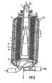
- FIG. 1 The operation of a radial adsorber for such an application is shown figure 1 .
- the fluid to be purified or separated 1 enters the lower part of the radial adsorber 10, passes through the adsorbent mass 20 and the purified fluid leaves the upper part 2.
- the regeneration fluid 3 enters the countercurrent by the upper part, desorbs the impurities contained in the adsorbent mass 20 and the waste gas 4 leaves at the bottom.
- the adsorber itself 10 consists of a cylindrical shell of vertical axis AA and 2 funds.
- the adsorbent mass is held in place by means of a perforated outer grid 11 and an internally perforated internal grid 12 fixed on one side to the upper bottom and on the other side to a solid plate 13 in the lower part.
- the fluid to be purified or separated 1 circulates vertically at the periphery in the external free zone 14 between the cylindrical shell and the external grid, passes radially through the adsorbent mass 20 and then flows vertically in the internal free zone 15 before leaving the adsorber by the top. Regeneration is carried out in the opposite direction.
- the gas to be purified during the adsorption phase circulates from the periphery to the center: it is called centripetal circulation in adsorption.
- the corresponding regeneration is then carried out centrifugally, that is to say from the center to the outside.
- the radial adsorbers can be used in the same way with reverse circulation directions, that is to say in adsorption, for example, the gas to be treated will go from the inside towards the outside while in regeneration, the regeneration gas will circulate from outside to inside.
- Another possible arrangement is to add a circular sealing disc to split the adsorbent mass in two parts. It is then possible in the same radial adsorber to have in adsorption phase for example a centrifugal circulation in a first volume of adsorbent followed by a centripetal circulation in the upper volume of adsorbent.
- the adsorbent material may consist of one and the same adsorbent, for example zeolite X or doped activated alumina, or may comprise several beds.
- multilayers of the type water-resistant silica gel, standard silica gel or activated alumina, zeolite X
- of the type sica gel or activated alumina, zeolite X, exchanged zeolite.
- the figure 2 represents, for example, a radial adsorber comprising two distinct layers of adsorbents.
- Perforated mesh means a gas permeable system impervious to adsorbent particles and having sufficient mechanical characteristics to ensure reliable operation for several years.
- a grid may be composed of several elements, for example a grid of thickness 6 or 8 mm with large openings on which is plated a metal fabric opening less than mm.
- the internal gate is the grid closest to the central axis, the outer gate the grid closest to the outer wall of the adsorber.
- intermediate grids In practice, if N is the number of adsorbent layers, N-1 intermediate grids must be used, ie N + 1 grids in all.
- the invention relates more particularly to the construction of said radial adsorbers.
- the main components of such a radial adsorber namely in our example of the Figure 2 : 3 perforated grids (5,6,7), their lower base (8), the connecting pieces between the grids and a bottom (12), the two bottoms (10 and 11) and the outer shell (9).
- This system makes it possible to hold in place the adsorbents constituting the cylindrical beds (3) and (4).
- the connecting pieces (12) can be of different shapes and sizes depending on the exact technology adopted for the adsorbers. They may for example include removable hatches to access inter-grid spaces or the space between outer gate and ferrule. In other designs, these are only parts for fixing the grids with their ends. They are generally designed to avoid preferential gas paths in the upper part.
- each of the grids consists of a perforated sheet ensuring mechanical strength, rolled into a cylinder and equipped with a wire mesh whose openings are appropriately selected to hold the adsorbent particles in place.
- These grids are made horizontally with the help of appropriate equipment classically existing in the boilermaking companies (perforators, bending machines, welding machines, turners, overhead cranes, gantries ).
- the wire mesh is plated on the grids and fixed to them by suitable systems (rods, washers, nuts, staples ).
- the face on which the wire mesh is applied is normally chosen such that the adsorbent applies it to the grid during filling or in normal operation.
- the ferrule is also manufactured horizontally from metal sheets, usually carbon steel or sometimes stainless steel.
- the bottoms are also equipped with their openings and flanges and prepared to be attached to the ferrule.
- the next step is threading and then assembling successive grids and the ferrule.
- the system is made integral with the base (8), at least one bottom (10,11) and optionally to the connecting pieces (12).
- Threading and assembly are conventionally "vertical”, that is to say that the different grids are hooked to a lifting system (crane, gantry crane) by one of their end so that their axis is vertical .
- the two main variants of the vertical assembly consist in assembling the different perforated grids either on their base 8 or on a bottom 10 or 11 using, if necessary, the connecting pieces 12.
- the "part of assembly” will be called the part on which will be fixed first grids, whether the lower base 8 or one of the bottom of the adsorber 10, 11.
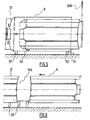
- the figure 3a illustrates the establishment of the intermediate grid 6 while the internal grid 7 has already been fixed to the base 8.
- the intermediate gate is operated by means of a traveling crane represented by its slings 200.
- the figure 3b shows on its side the establishment of the intermediate grid 6 in the case where the assembly of the grids is done using a bottom of the adsorber 10.
- the crane, the crane or the gantry that allows to maneuver the grid is symbolized by slings 200.
- the establishment of the ferrule is usually done using the same lifting means.
- the figure 3c shows the establishment of the ferrule 9 already equipped with its upper bottom 10 which is lowered concentrically to 3 grids 5,6,7 fixed on their lower base (8).
- the figure 3d shows a variant in which it is the set of perforated grids fixed on their base which is lowered into the shell equipped with its upper bottom 10. Connecting parts 12 for fixing together grids and bottom have been shown on the Figures 3c and 3d .
- the finish of the adsorber and in particular the establishment and fixing of the bottom can be done by keeping vertically all grids-ferrule or by "setting" the same set horizontally and then finishing the 'assembly.
- the finish of the adsorber (setting up accessories, sanding, painting 7) is done while it is in the horizontal position, that is to say with its large axis parallel to the ground.
- Each additional meter of grid height requires an elevation of the lifting means of two meters due to the vertical threading.
- the outer shell can for its part, for weight problems, be threaded more easily by sections welded to each other.
- the system formed by the perforated grids and the upper bottom can be placed horizontally after manufacture vertically and the ferrule threaded horizontally.
- Spacers, centering pieces, supports ... can be set up temporarily or permanently to facilitate handling.
- the workshop with sufficient capacities may be relatively far from the site where the adsorbers are to be located. Transport from the workshop to the site can itself be problematic. Overall distance from the workshops, lack of competition leads to excessive costs for these radial adsorbers.
- a solution of the invention is a method of assembling at least one radial adsorber comprising at least two concentric perforated grids, an upper bottom 10, a bottom bottom 11, an assembly part, which is a lower base 8 or the lower bottom 11 of said adsorber, and a cylindrical shell 9 of the same axis as said grids, characterized in that said perforated grids are assembled concentrically horizontally.
- the base 101 integral with the support 100 rotates about its central axis.
- said device D comprises two bases 101 disposed on either side of the support 100.
- the lifting means 201 is preferably a traveling crane.
- the assembly part is a lower base 8, a bottom bottom 11 or an upper bottom 10 of the radial adsorber. It is also conceivable to have an assembly part for an upper bottom 10 to which will be attached the perforated grids of the radial adsorber.
- the support 100 is of shape and mass such that it can support the loads that are fixed to it.
- the support can itself be fixed to the ground by suitable means.
- base will be used to define the plate, possibly in the form of a disk, and more generally the system on which the assembly part is fixed.
- This assembly part as already indicated will generally be either the support base of the grids, or the lower bottom 11 of the adsorber.
- the support (100) and the base (101) may be one and the same piece providing the two functions, on the one hand “fixing” to the assembly part, on the other hand “holding” said adsorber in position horizontal.
- the grids are fixed to a lower base 8 between steps a) and b1) or b2).
- the expression "a ferrule is positioned" means that the ferrule is threaded around the grids, or that the grids are introduced inside the ferrule.
- the Figures 4a and 4b illustrate the assembly method, taking as an example the method in which the assembly part is the lower base 8.
- the Figure 4a shows the positioning of the first grid 7 (internal grid) by means of two cranes 201 and 202. Once attached to the lower base 8, the first grid 7 is kept in equilibrium as shown in FIG. figure 4b . Indeed, the support 100 has a sufficient mass or is sufficiently secured to the ground to keep the grid in balance without any support or outside help.
- the figure 4b also shows how is threaded the second grid 6 concentrically to the first.
- the rotation of the base causing the rotation of the base and the grid makes it possible to carry out the welding in an optimal manner, that is to say without having to move the welding apparatus around the gate (or ferrule) .
- the support must be able to hold cantilevered all the perforated grids. Depending on the size of the adsorber, this represents tens to hundreds of tons. This balance can if necessary be obtained by creating a lever effect on the opposite side of the adsorber. It can be counter-weight or fixation in the ground.
- All the grids and the lower base 8 are then introduced into the outer shell 9 to which the bottom 10 has been previously welded.
- it can be used jointly crane 200 and mobile support carriage 30 controlled by a control box 31.
- the ferrule being smooth, the carriage 30 can move horizontally without problems.
- the ferrule itself is supported by turning cradles 32. After fixing the grids to the ferrule and wedging, it is then possible to rotate the assembly. This facilitates the final operations.
- the height of the perforated grids exceeds a certain value, generally from 10 to 15 m according to the characteristics of said grids (diameter, perforation ratio, etc.) in the case of radial adsorbers intended for air purifications.
- the perforated grids have a "inertia" lower than a non-perforated cylinder, which causes a relatively large deflection towards the ground (arrow) of the free end of the grids when they are horizontally fixed to their support.
- the Figure 8 illustrates this point and defines the arrow (f) as used in the rest of the text.
- the arrow is the vertical distance between on the one hand the center of the free end of a grid, assumed to be parallel to the ground over its entire length (that is to say not undergoing any deformation), and secondly the center of the free end of this same grid undergoing a deviation under the effect of its weight.
- Free end means the end of the grid which is not fixed to the lower base 8 (or more generally to the assembly part) and therefore not supported directly by the support 100.
- the arrow (f) is even more important than the grid is long. It varies in first approximation as the length to the power 4.
- steps a) to d) are repeated with the remaining grids of the radial adsorber, each time considering that the smaller diameter grid is the last grid welded. at the bottom 8.
- steps a) to d) are repeated with the remaining grids of the radial adsorber, each time considering that the smaller diameter grid is the last grid welded. bottom bottom 11.
- steps a) to d) are repeated with the remaining grids of the radial adsorber, each time considering that the smaller diameter grid is the last grid welded. at the top 10.
- the grids are fixed to a lower base 8 between steps e) and f1) or f2).
- This method makes it possible to construct horizontal radial adsorbers comprising perforated grids of height up to about 12 to 25m (according to the characteristics of said grids: diameter, rate and type of perforations ..)
- the lower bases on which the grids can be fixed generally have diameters ranging from 2 to 6 meters. The same is true of the bottom of the adsorber (2 to 7 meters). These dimensions are often fixed by transport constraints. From the point of view of assembly, nothing prevents to have larger diameters from the moment the tools (crane, device D) are provided for.
- the description given above defines the principles of the assembly which are the subject of the invention. Variations are possible without changing the characteristics of the assembly horizontally.
- the mobile support which is used in the case of grid of great length and / or very flexible can be placed not in the middle of the latter but for example closer to the end supported so to allow just the threading of the grid of greater diameter.
- the establishment of the mechanical means 60 will then be simplified (shorter distance to the grid to support).
- the Figure 7 illustrates the method of assembling at least one radial adsorber comprising grids of height greater than 12 m and posing a problem of threading because of the natural arrow resulting therefrom, taking as an example the method in which the part of assembly is the lower base 8.
- the inner grid 7 after being fixed to the lower base 8 is held at about its mid-length by a movable support 50. Because of the support, the arrow f to the free end is much weaker than the arrow that there would be without support. This arrow can be reduced as an example to a value of about ten centimeters or less, while without support, it could reach and exceed one meter.
- a second step the following grid 6 is threaded around the first grid by the mobile lifting means 201, 202 (preferably traveling crane) and this until the end of the grid to be fixed to the common support is close to the support of the inner grid. While the grids are in this position, an "arm" 60 is threaded into the free end (opposite the base 100 and the lower base 8) of the grid that is to be put on. This arm is manipulated to come into contact with the free end of the internal grid. This arm is integral with its support 61 by means of a rack 62. A counterweight 63 makes it possible, if necessary, to balance the force to be supplied to the end of the arm in order to hold the grid in place or even to straighten it out. 7.
- the Figure 7 illustrates the moment when the arm maintains the internal grid and where it is then possible to remove the mobile support 50 without risk that the internal grid comes because of its natural arrow to rely on the outer grid thus preventing the continuation of the setting up said grids.
- the system formed of the grids and the lower base 8 being formed, the threading of the ferrule can then be carried out according to one of the procedures already described.
- a construction is allowed horizontally by maintaining at least one of the grids by a support (support, arm).
- a “stiffener system” may be temporarily installed during construction on one or more grids and then limit the boom. In principle, it is a tool attached to the inside or outside of the grid, longitudinally, along one or more generators. This device stiffens the grid by limiting the flexibility caused in part by the perforations: it blocks the basic cylindrical geometry by limiting elongation and / or compression.
- the stiffener 90 is fixed on a generatrix of the grid 7. Preferably, it will be installed on the face of the grid on which there is no wire cloth, so as not to risk damaging the latter. It consists of a rigid piece approximately the length of the grid to support and secured to the latter by a suitable fastening system.
- stiffeners can be dismantled after placement of support to maintain the concentricity of the grids. They may possibly be left in place to increase the rigidity of the grids during the operation of the adsorber.
Landscapes
- Chemical & Material Sciences (AREA)
- Engineering & Computer Science (AREA)
- Analytical Chemistry (AREA)
- General Chemical & Material Sciences (AREA)
- Oil, Petroleum & Natural Gas (AREA)
- Chemical Kinetics & Catalysis (AREA)
- Separation Of Gases By Adsorption (AREA)
- Treatment Of Liquids With Adsorbents In General (AREA)
- Butt Welding And Welding Of Specific Article (AREA)
- Gas Separation By Absorption (AREA)
- Solid-Sorbent Or Filter-Aiding Compositions (AREA)
Priority Applications (1)
| Application Number | Priority Date | Filing Date | Title |
|---|---|---|---|
| PL09756009T PL2340102T3 (pl) | 2008-10-21 | 2009-10-12 | Sposób budowy mający zastosowanie do adsorberów promiennikowych dużych rozmiarów |
Applications Claiming Priority (2)
| Application Number | Priority Date | Filing Date | Title |
|---|---|---|---|
| FR0857132A FR2937257A1 (fr) | 2008-10-21 | 2008-10-21 | Methode de construction applicable aux adsorbeurs radiaux de grosse taille |
| PCT/FR2009/051938 WO2010046579A1 (fr) | 2008-10-21 | 2009-10-12 | Methode de construction applicable aux adsorbeurs radiaux de grosse taille |
Publications (2)
| Publication Number | Publication Date |
|---|---|
| EP2340102A1 EP2340102A1 (fr) | 2011-07-06 |
| EP2340102B1 true EP2340102B1 (fr) | 2014-06-04 |
Family
ID=40568513
Family Applications (1)
| Application Number | Title | Priority Date | Filing Date |
|---|---|---|---|
| EP09756009.8A Active EP2340102B1 (fr) | 2008-10-21 | 2009-10-12 | Methode de construction applicable aux adsorbeurs radiaux de grosse taille |
Country Status (15)
| Country | Link |
|---|---|
| US (1) | US20110197422A1 (pl) |
| EP (1) | EP2340102B1 (pl) |
| CN (1) | CN102196854B (pl) |
| AU (1) | AU2009306228A1 (pl) |
| BR (1) | BRPI0920632A2 (pl) |
| CA (1) | CA2736366C (pl) |
| ES (1) | ES2488498T3 (pl) |
| FR (1) | FR2937257A1 (pl) |
| MY (1) | MY155442A (pl) |
| PL (1) | PL2340102T3 (pl) |
| PT (1) | PT2340102E (pl) |
| RU (1) | RU2011120429A (pl) |
| UA (1) | UA105905C2 (pl) |
| WO (1) | WO2010046579A1 (pl) |
| ZA (1) | ZA201102600B (pl) |
Families Citing this family (11)
| Publication number | Priority date | Publication date | Assignee | Title |
|---|---|---|---|---|
| CN102068872B (zh) * | 2010-12-22 | 2013-03-27 | 杭州杭氧股份有限公司 | 一种径向流吸附器 |
| FR2982779B1 (fr) * | 2011-11-18 | 2013-12-27 | Rhodia Operations | Dispositif et procede de traitement d'un flux sur un produit solide contenu dans un panier dilatable |
| FR2993786B1 (fr) * | 2012-07-25 | 2015-04-17 | Air Liquide | Installation de purification d'un flux gazeux humide, contenant du co2 et des nox |
| FR3019060B1 (fr) * | 2014-03-28 | 2017-12-08 | L'air Liquide Sa Pour L'etude Et L'exploitation Des Procedes Georges Claude | Installation et procede de purification par adsorption d'un flux gazeux comprenant une impurete corrosive |
| CN105771536B (zh) * | 2016-03-11 | 2018-03-02 | 神华集团有限责任公司 | 气体吸附装置 |
| CN112692461A (zh) * | 2020-11-27 | 2021-04-23 | 杭州制氧机集团股份有限公司 | 一种径向流吸附器的卧式组装方法 |
| US11266951B1 (en) | 2021-06-11 | 2022-03-08 | Joseph J. Stark | System and method for improving the performance and lowering the cost of atmospheric carbon dioxide removal by direct air capture |
| US11266943B1 (en) * | 2021-06-11 | 2022-03-08 | Joseph J. Stark | System and method for improving the performance and lowering the cost of atmospheric carbon dioxide removal by direct air capture |
| US11389761B1 (en) * | 2021-06-11 | 2022-07-19 | Joseph J. Stark | System and method for improving the performance and lowering the cost of atmospheric carbon dioxide removal by direct air capture |
| US12194408B1 (en) | 2023-11-02 | 2025-01-14 | Air To Earth Holdings Llc | System and method for carbon dioxide removal by direct air capture |
| US12201963B1 (en) | 2023-11-02 | 2025-01-21 | Air To Earth Holdings Llc | System and method for carbon dioxide removal by direct air capture |
Family Cites Families (28)
| Publication number | Priority date | Publication date | Assignee | Title |
|---|---|---|---|---|
| US2511967A (en) * | 1950-06-20 | Gas and liquto separator | ||
| US2687780A (en) * | 1951-12-28 | 1954-08-31 | Frank R Culhane | Gas cleaning apparatus |
| US2891630A (en) * | 1956-04-30 | 1959-06-23 | Cons Electrodynamics Corp | Chromatography |
| US2953217A (en) * | 1959-02-24 | 1960-09-20 | Donaldson Co Inc | Wet type air cleaner with optionally usable auxiliary filter |
| DE1544066A1 (de) * | 1965-11-19 | 1970-02-26 | Linde Ag | Adsorptionsvorrichtung |
| DE2243251B2 (de) * | 1972-09-02 | 1976-01-02 | Paul Gillet Gmbh, 6732 Edenkoben | Vorrichtung zur Reinigung der Abgase von Brennkraftmaschinen |
| US3885933A (en) * | 1974-09-20 | 1975-05-27 | Stratford Eng Corp | Classifying centrifugal separator |
| FR2549406B1 (fr) * | 1983-07-22 | 1986-12-26 | Havre Chantiers | Procede et machines pour souder ou decouper automatiquement la jonction entre un tube principal et un tube secondaire en derivation |
| US4764346A (en) * | 1986-12-09 | 1988-08-16 | Pioneer Medical Systems, Inc. | Disposable rebreathing canister |
| US5027971A (en) * | 1990-10-04 | 1991-07-02 | The B. F. Goodrich Company | Reactor vessel |
| US5814129A (en) * | 1997-04-11 | 1998-09-29 | Air Products And Chemical, Inc. | Radial flow adsorption vessel |
| US5980840A (en) * | 1997-04-25 | 1999-11-09 | Bp Amoco Corporation | Autothermic reactor and process using oxygen ion--conducting dense ceramic membrane |
| CN1205909A (zh) * | 1997-06-12 | 1999-01-27 | 液体空气乔治洛德方法利用和研究有限公司 | 利用吸附作用分离空气的工艺和装置 |
| DE19746698C2 (de) * | 1997-10-22 | 1999-12-30 | Linde Ag | Reaktor |
| US6139810A (en) * | 1998-06-03 | 2000-10-31 | Praxair Technology, Inc. | Tube and shell reactor with oxygen selective ion transport ceramic reaction tubes |
| US6770120B2 (en) * | 2002-05-01 | 2004-08-03 | Praxair Technology, Inc. | Radial adsorption gas separation apparatus and method of use |
| US20040134147A1 (en) * | 2003-01-09 | 2004-07-15 | Warren James William | Treatment of weep hole |
| FR2856607B1 (fr) * | 2003-06-27 | 2006-08-18 | Air Liquide | Procede de purification d'air par cycle tsa accelere |
| FR2856937B1 (fr) * | 2003-07-02 | 2005-08-19 | Air Liquide | Appareil pour la separation par adsorption a variation de pression d'au moins un constituant d'un melange gazeux |
| FR2887783B1 (fr) * | 2005-07-04 | 2007-11-16 | Air Liquide | Structure plane formee d'une matrice et de materiaux a changement de phase utilisable pour le traitement des gaz |
| FR2895790B1 (fr) * | 2005-12-29 | 2008-09-12 | Framatome Anp Sas | Dispositif et procede d'intervention dans une boite a eau d'un echangeur de chaleur. |
| WO2007149978A2 (en) * | 2006-06-22 | 2007-12-27 | Honeywell International Inc. | Hydrocarbon adsorber for air induction systems |
| FR2909899A1 (fr) * | 2006-12-14 | 2008-06-20 | Air Liquide | Adsorbeurs radiaux installes en parallele |
| FR2911077B1 (fr) * | 2007-01-05 | 2009-11-27 | Air Liquide | Procede de purification ou de separatiion utilisant plusieurs adsorbeurs decales en phase |
| US7785402B2 (en) * | 2007-05-07 | 2010-08-31 | Crawford Martin J | Removable verticle media insert system for air treatment |
| DE202007013822U1 (de) * | 2007-10-02 | 2009-02-19 | Mann+Hummel Gmbh | Filterelement und Filtersystem |
| EP2070590A1 (en) * | 2007-12-11 | 2009-06-17 | Methanol Casale S.A. | Supporting system of heat-exchange plates in isothermal chemical reactors |
| US20090211965A1 (en) * | 2008-02-21 | 2009-08-27 | Weatherford/Lamb, Inc. | Arrangement for splicing panels together to form a cylindrical screen |
-
2008
- 2008-10-21 FR FR0857132A patent/FR2937257A1/fr active Pending
-
2009
- 2009-10-12 PL PL09756009T patent/PL2340102T3/pl unknown
- 2009-10-12 MY MYPI2011001050A patent/MY155442A/en unknown
- 2009-10-12 EP EP09756009.8A patent/EP2340102B1/fr active Active
- 2009-10-12 BR BRPI0920632A patent/BRPI0920632A2/pt not_active Application Discontinuation
- 2009-10-12 CN CN2009801417103A patent/CN102196854B/zh active Active
- 2009-10-12 PT PT97560098T patent/PT2340102E/pt unknown
- 2009-10-12 WO PCT/FR2009/051938 patent/WO2010046579A1/fr not_active Ceased
- 2009-10-12 CA CA2736366A patent/CA2736366C/fr active Active
- 2009-10-12 AU AU2009306228A patent/AU2009306228A1/en not_active Abandoned
- 2009-10-12 RU RU2011120429/05A patent/RU2011120429A/ru not_active Application Discontinuation
- 2009-10-12 US US13/125,248 patent/US20110197422A1/en not_active Abandoned
- 2009-10-12 ES ES09756009.8T patent/ES2488498T3/es active Active
- 2009-12-10 UA UAA201104904A patent/UA105905C2/uk unknown
-
2011
- 2011-04-07 ZA ZA2011/02600A patent/ZA201102600B/en unknown
Also Published As
| Publication number | Publication date |
|---|---|
| PT2340102E (pt) | 2014-08-25 |
| WO2010046579A1 (fr) | 2010-04-29 |
| CN102196854B (zh) | 2013-12-25 |
| RU2011120429A (ru) | 2012-11-27 |
| US20110197422A1 (en) | 2011-08-18 |
| UA105905C2 (uk) | 2014-07-10 |
| PL2340102T3 (pl) | 2014-11-28 |
| CN102196854A (zh) | 2011-09-21 |
| AU2009306228A1 (en) | 2010-04-29 |
| FR2937257A1 (fr) | 2010-04-23 |
| ES2488498T3 (es) | 2014-08-27 |
| MY155442A (en) | 2015-10-15 |
| ZA201102600B (en) | 2012-01-25 |
| CA2736366A1 (fr) | 2010-04-29 |
| EP2340102A1 (fr) | 2011-07-06 |
| BRPI0920632A2 (pt) | 2016-01-12 |
| CA2736366C (fr) | 2017-07-04 |
Similar Documents
| Publication | Publication Date | Title |
|---|---|---|
| EP2340102B1 (fr) | Methode de construction applicable aux adsorbeurs radiaux de grosse taille | |
| FR2938451B1 (fr) | Adsorbeurs radiaux monolits en serie | |
| EP1095689B1 (fr) | Installation de traitement cyclique de fluide par adsorption avec vannes à étanchéité améliorée | |
| EP1638669A1 (fr) | Procede de prepurification d'air par cycle tsa accelere | |
| EP0500416B1 (fr) | Procédé de production d'oxygène par adsorption | |
| EP0480840B1 (fr) | Procédé et équipement de séparation par adsorption d'au moins un constituant d'un mélange gazeux | |
| EP2129449B1 (fr) | Procédé et installation de purification ou de séparation utilisant plusieurs adsorbeurs décalés en phase | |
| FR2775198A1 (fr) | Procede et dispositif de purification de gaz par adsorption a lits horizontaux fixes | |
| FR2804618A1 (fr) | Procede de decarbonation de gaz brules, et appareil de decarbonation | |
| EP3122439B1 (fr) | Installation et procede de purification par adsorption d'un flux gazeux comprenant une impurete corrosive | |
| JP2014509558A5 (pl) | ||
| FR2970184A1 (fr) | Composition zeolitique adaptee a l'epuration d'air | |
| WO2020169900A1 (fr) | Installation et procédé de séparation des gaz de l'air mettant en œuvre un adsorbeur de forme parallélépipédique | |
| CN114222619A (zh) | 制造高填充率复合吸附体床层的方法、包括床层的吸附器和使用吸附器的基于吸附的气体分离 | |
| WO2020169899A1 (fr) | Procédé et installation de purification d'un flux gazeux de débit élevé | |
| FR2806321A1 (fr) | Procede et reacteur de traitement d'un gaz au moyen d'un garnissage actif regenerable | |
| WO2020169901A1 (fr) | Installation et procédé de séparation des gaz de l'air à basse pression | |
| EP1022056A1 (fr) | Installation de traitement de fluide comportant plusieurs lits de particules maintenus par une grille de séparation | |
| FR2988623A1 (fr) | Reduction des volumes morts d'un adsorbeur pour adsorption d'un flux gazeux | |
| EP2181752B1 (fr) | Procédé de traitement de fluide par adsorption à variation de pression | |
| WO2013004932A1 (fr) | Procédé de purification d'un flux gazeux avec contrôle de la pureté | |
| WO2008078028A2 (fr) | Adsorbeurs radiaux installes en parallele | |
| FR3096278A1 (fr) | Procédé de réglage d’une unité de production d’oxygène par comparaison des pressions différentielles caractéristiques des différents adsorbeurs | |
| FR3120316A1 (fr) | Adsorbeur radial à circulation radiale d'un gaz | |
| FR3083718A1 (fr) | Dispositif en toile permettant de limiter ou supprimer la migration de particules entre deux couches |
Legal Events
| Date | Code | Title | Description |
|---|---|---|---|
| PUAI | Public reference made under article 153(3) epc to a published international application that has entered the european phase |
Free format text: ORIGINAL CODE: 0009012 |
|
| 17P | Request for examination filed |
Effective date: 20110523 |
|
| AK | Designated contracting states |
Kind code of ref document: A1 Designated state(s): AT BE BG CH CY CZ DE DK EE ES FI FR GB GR HR HU IE IS IT LI LT LU LV MC MK MT NL NO PL PT RO SE SI SK SM TR |
|
| AX | Request for extension of the european patent |
Extension state: AL BA RS |
|
| DAX | Request for extension of the european patent (deleted) | ||
| GRAP | Despatch of communication of intention to grant a patent |
Free format text: ORIGINAL CODE: EPIDOSNIGR1 |
|
| INTG | Intention to grant announced |
Effective date: 20131217 |
|
| GRAS | Grant fee paid |
Free format text: ORIGINAL CODE: EPIDOSNIGR3 |
|
| GRAA | (expected) grant |
Free format text: ORIGINAL CODE: 0009210 |
|
| AK | Designated contracting states |
Kind code of ref document: B1 Designated state(s): AT BE BG CH CY CZ DE DK EE ES FI FR GB GR HR HU IE IS IT LI LT LU LV MC MK MT NL NO PL PT RO SE SI SK SM TR |
|
| REG | Reference to a national code |
Ref country code: GB Ref legal event code: FG4D Free format text: NOT ENGLISH |
|
| REG | Reference to a national code |
Ref country code: CH Ref legal event code: EP |
|
| REG | Reference to a national code |
Ref country code: AT Ref legal event code: REF Ref document number: 670726 Country of ref document: AT Kind code of ref document: T Effective date: 20140615 |
|
| REG | Reference to a national code |
Ref country code: IE Ref legal event code: FG4D Free format text: LANGUAGE OF EP DOCUMENT: FRENCH |
|
| REG | Reference to a national code |
Ref country code: DE Ref legal event code: R096 Ref document number: 602009024463 Country of ref document: DE Effective date: 20140710 |
|
| REG | Reference to a national code |
Ref country code: PT Ref legal event code: SC4A Free format text: AVAILABILITY OF NATIONAL TRANSLATION Effective date: 20140804 |
|
| REG | Reference to a national code |
Ref country code: ES Ref legal event code: FG2A Ref document number: 2488498 Country of ref document: ES Kind code of ref document: T3 Effective date: 20140827 |
|
| REG | Reference to a national code |
Ref country code: AT Ref legal event code: MK05 Ref document number: 670726 Country of ref document: AT Kind code of ref document: T Effective date: 20140604 |
|
| REG | Reference to a national code |
Ref country code: NL Ref legal event code: VDEP Effective date: 20140604 |
|
| PG25 | Lapsed in a contracting state [announced via postgrant information from national office to epo] |
Ref country code: GR Free format text: LAPSE BECAUSE OF FAILURE TO SUBMIT A TRANSLATION OF THE DESCRIPTION OR TO PAY THE FEE WITHIN THE PRESCRIBED TIME-LIMIT Effective date: 20140905 Ref country code: NO Free format text: LAPSE BECAUSE OF FAILURE TO SUBMIT A TRANSLATION OF THE DESCRIPTION OR TO PAY THE FEE WITHIN THE PRESCRIBED TIME-LIMIT Effective date: 20140904 Ref country code: FI Free format text: LAPSE BECAUSE OF FAILURE TO SUBMIT A TRANSLATION OF THE DESCRIPTION OR TO PAY THE FEE WITHIN THE PRESCRIBED TIME-LIMIT Effective date: 20140604 Ref country code: CY Free format text: LAPSE BECAUSE OF FAILURE TO SUBMIT A TRANSLATION OF THE DESCRIPTION OR TO PAY THE FEE WITHIN THE PRESCRIBED TIME-LIMIT Effective date: 20140604 Ref country code: LT Free format text: LAPSE BECAUSE OF FAILURE TO SUBMIT A TRANSLATION OF THE DESCRIPTION OR TO PAY THE FEE WITHIN THE PRESCRIBED TIME-LIMIT Effective date: 20140604 |
|
| REG | Reference to a national code |
Ref country code: LT Ref legal event code: MG4D |
|
| PG25 | Lapsed in a contracting state [announced via postgrant information from national office to epo] |
Ref country code: HR Free format text: LAPSE BECAUSE OF FAILURE TO SUBMIT A TRANSLATION OF THE DESCRIPTION OR TO PAY THE FEE WITHIN THE PRESCRIBED TIME-LIMIT Effective date: 20140604 Ref country code: SE Free format text: LAPSE BECAUSE OF FAILURE TO SUBMIT A TRANSLATION OF THE DESCRIPTION OR TO PAY THE FEE WITHIN THE PRESCRIBED TIME-LIMIT Effective date: 20140604 Ref country code: AT Free format text: LAPSE BECAUSE OF FAILURE TO SUBMIT A TRANSLATION OF THE DESCRIPTION OR TO PAY THE FEE WITHIN THE PRESCRIBED TIME-LIMIT Effective date: 20140604 Ref country code: LV Free format text: LAPSE BECAUSE OF FAILURE TO SUBMIT A TRANSLATION OF THE DESCRIPTION OR TO PAY THE FEE WITHIN THE PRESCRIBED TIME-LIMIT Effective date: 20140604 |
|
| REG | Reference to a national code |
Ref country code: PL Ref legal event code: T3 |
|
| PG25 | Lapsed in a contracting state [announced via postgrant information from national office to epo] |
Ref country code: RO Free format text: LAPSE BECAUSE OF FAILURE TO SUBMIT A TRANSLATION OF THE DESCRIPTION OR TO PAY THE FEE WITHIN THE PRESCRIBED TIME-LIMIT Effective date: 20140604 Ref country code: SK Free format text: LAPSE BECAUSE OF FAILURE TO SUBMIT A TRANSLATION OF THE DESCRIPTION OR TO PAY THE FEE WITHIN THE PRESCRIBED TIME-LIMIT Effective date: 20140604 Ref country code: EE Free format text: LAPSE BECAUSE OF FAILURE TO SUBMIT A TRANSLATION OF THE DESCRIPTION OR TO PAY THE FEE WITHIN THE PRESCRIBED TIME-LIMIT Effective date: 20140604 |
|
| PG25 | Lapsed in a contracting state [announced via postgrant information from national office to epo] |
Ref country code: NL Free format text: LAPSE BECAUSE OF FAILURE TO SUBMIT A TRANSLATION OF THE DESCRIPTION OR TO PAY THE FEE WITHIN THE PRESCRIBED TIME-LIMIT Effective date: 20140604 Ref country code: IS Free format text: LAPSE BECAUSE OF FAILURE TO SUBMIT A TRANSLATION OF THE DESCRIPTION OR TO PAY THE FEE WITHIN THE PRESCRIBED TIME-LIMIT Effective date: 20141004 |
|
| REG | Reference to a national code |
Ref country code: DE Ref legal event code: R097 Ref document number: 602009024463 Country of ref document: DE |
|
| PLBE | No opposition filed within time limit |
Free format text: ORIGINAL CODE: 0009261 |
|
| STAA | Information on the status of an ep patent application or granted ep patent |
Free format text: STATUS: NO OPPOSITION FILED WITHIN TIME LIMIT |
|
| PG25 | Lapsed in a contracting state [announced via postgrant information from national office to epo] |
Ref country code: DK Free format text: LAPSE BECAUSE OF FAILURE TO SUBMIT A TRANSLATION OF THE DESCRIPTION OR TO PAY THE FEE WITHIN THE PRESCRIBED TIME-LIMIT Effective date: 20140604 |
|
| 26N | No opposition filed |
Effective date: 20150305 |
|
| PG25 | Lapsed in a contracting state [announced via postgrant information from national office to epo] |
Ref country code: MC Free format text: LAPSE BECAUSE OF FAILURE TO SUBMIT A TRANSLATION OF THE DESCRIPTION OR TO PAY THE FEE WITHIN THE PRESCRIBED TIME-LIMIT Effective date: 20140604 Ref country code: LU Free format text: LAPSE BECAUSE OF FAILURE TO SUBMIT A TRANSLATION OF THE DESCRIPTION OR TO PAY THE FEE WITHIN THE PRESCRIBED TIME-LIMIT Effective date: 20141012 |
|
| REG | Reference to a national code |
Ref country code: CH Ref legal event code: PL |
|
| REG | Reference to a national code |
Ref country code: DE Ref legal event code: R097 Ref document number: 602009024463 Country of ref document: DE Effective date: 20150305 |
|
| GBPC | Gb: european patent ceased through non-payment of renewal fee |
Effective date: 20141012 |
|
| PG25 | Lapsed in a contracting state [announced via postgrant information from national office to epo] |
Ref country code: BE Free format text: LAPSE BECAUSE OF NON-PAYMENT OF DUE FEES Effective date: 20141031 |
|
| REG | Reference to a national code |
Ref country code: IE Ref legal event code: MM4A |
|
| PG25 | Lapsed in a contracting state [announced via postgrant information from national office to epo] |
Ref country code: LI Free format text: LAPSE BECAUSE OF NON-PAYMENT OF DUE FEES Effective date: 20141031 Ref country code: GB Free format text: LAPSE BECAUSE OF NON-PAYMENT OF DUE FEES Effective date: 20141012 Ref country code: CH Free format text: LAPSE BECAUSE OF NON-PAYMENT OF DUE FEES Effective date: 20141031 Ref country code: SI Free format text: LAPSE BECAUSE OF FAILURE TO SUBMIT A TRANSLATION OF THE DESCRIPTION OR TO PAY THE FEE WITHIN THE PRESCRIBED TIME-LIMIT Effective date: 20140604 |
|
| REG | Reference to a national code |
Ref country code: FR Ref legal event code: PLFP Year of fee payment: 7 |
|
| PG25 | Lapsed in a contracting state [announced via postgrant information from national office to epo] |
Ref country code: IE Free format text: LAPSE BECAUSE OF NON-PAYMENT OF DUE FEES Effective date: 20141012 |
|
| PG25 | Lapsed in a contracting state [announced via postgrant information from national office to epo] |
Ref country code: SM Free format text: LAPSE BECAUSE OF FAILURE TO SUBMIT A TRANSLATION OF THE DESCRIPTION OR TO PAY THE FEE WITHIN THE PRESCRIBED TIME-LIMIT Effective date: 20140604 |
|
| PG25 | Lapsed in a contracting state [announced via postgrant information from national office to epo] |
Ref country code: BG Free format text: LAPSE BECAUSE OF FAILURE TO SUBMIT A TRANSLATION OF THE DESCRIPTION OR TO PAY THE FEE WITHIN THE PRESCRIBED TIME-LIMIT Effective date: 20140604 |
|
| PG25 | Lapsed in a contracting state [announced via postgrant information from national office to epo] |
Ref country code: HU Free format text: LAPSE BECAUSE OF FAILURE TO SUBMIT A TRANSLATION OF THE DESCRIPTION OR TO PAY THE FEE WITHIN THE PRESCRIBED TIME-LIMIT; INVALID AB INITIO Effective date: 20091012 Ref country code: MT Free format text: LAPSE BECAUSE OF FAILURE TO SUBMIT A TRANSLATION OF THE DESCRIPTION OR TO PAY THE FEE WITHIN THE PRESCRIBED TIME-LIMIT Effective date: 20140604 |
|
| REG | Reference to a national code |
Ref country code: FR Ref legal event code: PLFP Year of fee payment: 8 |
|
| REG | Reference to a national code |
Ref country code: FR Ref legal event code: PLFP Year of fee payment: 9 |
|
| PG25 | Lapsed in a contracting state [announced via postgrant information from national office to epo] |
Ref country code: MK Free format text: LAPSE BECAUSE OF FAILURE TO SUBMIT A TRANSLATION OF THE DESCRIPTION OR TO PAY THE FEE WITHIN THE PRESCRIBED TIME-LIMIT Effective date: 20140604 |
|
| REG | Reference to a national code |
Ref country code: FR Ref legal event code: PLFP Year of fee payment: 10 |
|
| PGFP | Annual fee paid to national office [announced via postgrant information from national office to epo] |
Ref country code: PT Payment date: 20251002 Year of fee payment: 17 |
|
| PGFP | Annual fee paid to national office [announced via postgrant information from national office to epo] |
Ref country code: DE Payment date: 20251021 Year of fee payment: 17 |
|
| PGFP | Annual fee paid to national office [announced via postgrant information from national office to epo] |
Ref country code: IT Payment date: 20251022 Year of fee payment: 17 |
|
| PGFP | Annual fee paid to national office [announced via postgrant information from national office to epo] |
Ref country code: FR Payment date: 20251029 Year of fee payment: 17 |
|
| PGFP | Annual fee paid to national office [announced via postgrant information from national office to epo] |
Ref country code: TR Payment date: 20251006 Year of fee payment: 17 |
|
| PGFP | Annual fee paid to national office [announced via postgrant information from national office to epo] |
Ref country code: CZ Payment date: 20251009 Year of fee payment: 17 |
|
| PGFP | Annual fee paid to national office [announced via postgrant information from national office to epo] |
Ref country code: PL Payment date: 20251006 Year of fee payment: 17 |
|
| PGFP | Annual fee paid to national office [announced via postgrant information from national office to epo] |
Ref country code: ES Payment date: 20251210 Year of fee payment: 17 |