EP2340001B1 - Apparatus and methods for controlling tissue oxygenation for wound healing and promoting tissue viability - Google Patents
Apparatus and methods for controlling tissue oxygenation for wound healing and promoting tissue viability Download PDFInfo
- Publication number
- EP2340001B1 EP2340001B1 EP09822290.4A EP09822290A EP2340001B1 EP 2340001 B1 EP2340001 B1 EP 2340001B1 EP 09822290 A EP09822290 A EP 09822290A EP 2340001 B1 EP2340001 B1 EP 2340001B1
- Authority
- EP
- European Patent Office
- Prior art keywords
- oxygen
- tubing
- microprocessor
- tissue
- wound
- Prior art date
- Legal status (The legal status is an assumption and is not a legal conclusion. Google has not performed a legal analysis and makes no representation as to the accuracy of the status listed.)
- Active
Links
Images



Classifications
-
- A—HUMAN NECESSITIES
- A61—MEDICAL OR VETERINARY SCIENCE; HYGIENE
- A61F—FILTERS IMPLANTABLE INTO BLOOD VESSELS; PROSTHESES; DEVICES PROVIDING PATENCY TO, OR PREVENTING COLLAPSING OF, TUBULAR STRUCTURES OF THE BODY, e.g. STENTS; ORTHOPAEDIC, NURSING OR CONTRACEPTIVE DEVICES; FOMENTATION; TREATMENT OR PROTECTION OF EYES OR EARS; BANDAGES, DRESSINGS OR ABSORBENT PADS; FIRST-AID KITS
- A61F13/00—Bandages or dressings; Absorbent pads
- A61F13/05—Bandages or dressings; Absorbent pads specially adapted for use with sub-pressure or over-pressure therapy, wound drainage or wound irrigation, e.g. for use with negative-pressure wound therapy [NPWT]
-
- A—HUMAN NECESSITIES
- A61—MEDICAL OR VETERINARY SCIENCE; HYGIENE
- A61M—DEVICES FOR INTRODUCING MEDIA INTO, OR ONTO, THE BODY; DEVICES FOR TRANSDUCING BODY MEDIA OR FOR TAKING MEDIA FROM THE BODY; DEVICES FOR PRODUCING OR ENDING SLEEP OR STUPOR
- A61M35/00—Devices for applying media, e.g. remedies, on the human body
-
- A—HUMAN NECESSITIES
- A61—MEDICAL OR VETERINARY SCIENCE; HYGIENE
- A61M—DEVICES FOR INTRODUCING MEDIA INTO, OR ONTO, THE BODY; DEVICES FOR TRANSDUCING BODY MEDIA OR FOR TAKING MEDIA FROM THE BODY; DEVICES FOR PRODUCING OR ENDING SLEEP OR STUPOR
- A61M35/00—Devices for applying media, e.g. remedies, on the human body
- A61M35/003—Portable hand-held applicators having means for dispensing or spreading integral media
-
- A—HUMAN NECESSITIES
- A61—MEDICAL OR VETERINARY SCIENCE; HYGIENE
- A61M—DEVICES FOR INTRODUCING MEDIA INTO, OR ONTO, THE BODY; DEVICES FOR TRANSDUCING BODY MEDIA OR FOR TAKING MEDIA FROM THE BODY; DEVICES FOR PRODUCING OR ENDING SLEEP OR STUPOR
- A61M35/00—Devices for applying media, e.g. remedies, on the human body
- A61M35/30—Gas therapy for therapeutic treatment of the skin
-
- A—HUMAN NECESSITIES
- A61—MEDICAL OR VETERINARY SCIENCE; HYGIENE
- A61P—SPECIFIC THERAPEUTIC ACTIVITY OF CHEMICAL COMPOUNDS OR MEDICINAL PREPARATIONS
- A61P17/00—Drugs for dermatological disorders
- A61P17/02—Drugs for dermatological disorders for treating wounds, ulcers, burns, scars, keloids, or the like
-
- A—HUMAN NECESSITIES
- A61—MEDICAL OR VETERINARY SCIENCE; HYGIENE
- A61F—FILTERS IMPLANTABLE INTO BLOOD VESSELS; PROSTHESES; DEVICES PROVIDING PATENCY TO, OR PREVENTING COLLAPSING OF, TUBULAR STRUCTURES OF THE BODY, e.g. STENTS; ORTHOPAEDIC, NURSING OR CONTRACEPTIVE DEVICES; FOMENTATION; TREATMENT OR PROTECTION OF EYES OR EARS; BANDAGES, DRESSINGS OR ABSORBENT PADS; FIRST-AID KITS
- A61F13/00—Bandages or dressings; Absorbent pads
- A61F2013/00089—Wound bandages
- A61F2013/0017—Wound bandages possibility of applying fluid
-
- A—HUMAN NECESSITIES
- A61—MEDICAL OR VETERINARY SCIENCE; HYGIENE
- A61F—FILTERS IMPLANTABLE INTO BLOOD VESSELS; PROSTHESES; DEVICES PROVIDING PATENCY TO, OR PREVENTING COLLAPSING OF, TUBULAR STRUCTURES OF THE BODY, e.g. STENTS; ORTHOPAEDIC, NURSING OR CONTRACEPTIVE DEVICES; FOMENTATION; TREATMENT OR PROTECTION OF EYES OR EARS; BANDAGES, DRESSINGS OR ABSORBENT PADS; FIRST-AID KITS
- A61F13/00—Bandages or dressings; Absorbent pads
- A61F2013/00089—Wound bandages
- A61F2013/0017—Wound bandages possibility of applying fluid
- A61F2013/00174—Wound bandages possibility of applying fluid possibility of applying pressure
-
- A—HUMAN NECESSITIES
- A61—MEDICAL OR VETERINARY SCIENCE; HYGIENE
- A61F—FILTERS IMPLANTABLE INTO BLOOD VESSELS; PROSTHESES; DEVICES PROVIDING PATENCY TO, OR PREVENTING COLLAPSING OF, TUBULAR STRUCTURES OF THE BODY, e.g. STENTS; ORTHOPAEDIC, NURSING OR CONTRACEPTIVE DEVICES; FOMENTATION; TREATMENT OR PROTECTION OF EYES OR EARS; BANDAGES, DRESSINGS OR ABSORBENT PADS; FIRST-AID KITS
- A61F13/00—Bandages or dressings; Absorbent pads
- A61F2013/00089—Wound bandages
- A61F2013/00187—Wound bandages insulating; warmth or cold applying
- A61F2013/002—Wound bandages insulating; warmth or cold applying with temperature control
-
- A—HUMAN NECESSITIES
- A61—MEDICAL OR VETERINARY SCIENCE; HYGIENE
- A61F—FILTERS IMPLANTABLE INTO BLOOD VESSELS; PROSTHESES; DEVICES PROVIDING PATENCY TO, OR PREVENTING COLLAPSING OF, TUBULAR STRUCTURES OF THE BODY, e.g. STENTS; ORTHOPAEDIC, NURSING OR CONTRACEPTIVE DEVICES; FOMENTATION; TREATMENT OR PROTECTION OF EYES OR EARS; BANDAGES, DRESSINGS OR ABSORBENT PADS; FIRST-AID KITS
- A61F13/00—Bandages or dressings; Absorbent pads
- A61F2013/00089—Wound bandages
- A61F2013/00246—Wound bandages in a special way pervious to air or vapours
- A61F2013/00268—Wound bandages in a special way pervious to air or vapours impervious, i.e. occlusive bandage
-
- A—HUMAN NECESSITIES
- A61—MEDICAL OR VETERINARY SCIENCE; HYGIENE
- A61F—FILTERS IMPLANTABLE INTO BLOOD VESSELS; PROSTHESES; DEVICES PROVIDING PATENCY TO, OR PREVENTING COLLAPSING OF, TUBULAR STRUCTURES OF THE BODY, e.g. STENTS; ORTHOPAEDIC, NURSING OR CONTRACEPTIVE DEVICES; FOMENTATION; TREATMENT OR PROTECTION OF EYES OR EARS; BANDAGES, DRESSINGS OR ABSORBENT PADS; FIRST-AID KITS
- A61F13/00—Bandages or dressings; Absorbent pads
- A61F2013/00361—Plasters
- A61F2013/00365—Plasters use
- A61F2013/00536—Plasters use for draining or irrigating wounds
-
- A—HUMAN NECESSITIES
- A61—MEDICAL OR VETERINARY SCIENCE; HYGIENE
- A61F—FILTERS IMPLANTABLE INTO BLOOD VESSELS; PROSTHESES; DEVICES PROVIDING PATENCY TO, OR PREVENTING COLLAPSING OF, TUBULAR STRUCTURES OF THE BODY, e.g. STENTS; ORTHOPAEDIC, NURSING OR CONTRACEPTIVE DEVICES; FOMENTATION; TREATMENT OR PROTECTION OF EYES OR EARS; BANDAGES, DRESSINGS OR ABSORBENT PADS; FIRST-AID KITS
- A61F13/00—Bandages or dressings; Absorbent pads
- A61F2013/00361—Plasters
- A61F2013/00365—Plasters use
- A61F2013/0054—Plasters use for deep wounds
-
- A—HUMAN NECESSITIES
- A61—MEDICAL OR VETERINARY SCIENCE; HYGIENE
- A61F—FILTERS IMPLANTABLE INTO BLOOD VESSELS; PROSTHESES; DEVICES PROVIDING PATENCY TO, OR PREVENTING COLLAPSING OF, TUBULAR STRUCTURES OF THE BODY, e.g. STENTS; ORTHOPAEDIC, NURSING OR CONTRACEPTIVE DEVICES; FOMENTATION; TREATMENT OR PROTECTION OF EYES OR EARS; BANDAGES, DRESSINGS OR ABSORBENT PADS; FIRST-AID KITS
- A61F13/00—Bandages or dressings; Absorbent pads
- A61F2013/00361—Plasters
- A61F2013/00727—Plasters means for wound humidity control
- A61F2013/00731—Plasters means for wound humidity control with absorbing pads
-
- A—HUMAN NECESSITIES
- A61—MEDICAL OR VETERINARY SCIENCE; HYGIENE
- A61F—FILTERS IMPLANTABLE INTO BLOOD VESSELS; PROSTHESES; DEVICES PROVIDING PATENCY TO, OR PREVENTING COLLAPSING OF, TUBULAR STRUCTURES OF THE BODY, e.g. STENTS; ORTHOPAEDIC, NURSING OR CONTRACEPTIVE DEVICES; FOMENTATION; TREATMENT OR PROTECTION OF EYES OR EARS; BANDAGES, DRESSINGS OR ABSORBENT PADS; FIRST-AID KITS
- A61F13/00—Bandages or dressings; Absorbent pads
- A61F2013/00361—Plasters
- A61F2013/00855—Plasters pervious to air or vapours
- A61F2013/00872—Plasters pervious to air or vapours with controlled oxygen permeability
-
- A—HUMAN NECESSITIES
- A61—MEDICAL OR VETERINARY SCIENCE; HYGIENE
- A61F—FILTERS IMPLANTABLE INTO BLOOD VESSELS; PROSTHESES; DEVICES PROVIDING PATENCY TO, OR PREVENTING COLLAPSING OF, TUBULAR STRUCTURES OF THE BODY, e.g. STENTS; ORTHOPAEDIC, NURSING OR CONTRACEPTIVE DEVICES; FOMENTATION; TREATMENT OR PROTECTION OF EYES OR EARS; BANDAGES, DRESSINGS OR ABSORBENT PADS; FIRST-AID KITS
- A61F13/00—Bandages or dressings; Absorbent pads
- A61F2013/00361—Plasters
- A61F2013/00902—Plasters containing means
- A61F2013/0094—Plasters containing means for sensing physical parameters
- A61F2013/00953—Plasters containing means for sensing physical parameters temperature
-
- A—HUMAN NECESSITIES
- A61—MEDICAL OR VETERINARY SCIENCE; HYGIENE
- A61F—FILTERS IMPLANTABLE INTO BLOOD VESSELS; PROSTHESES; DEVICES PROVIDING PATENCY TO, OR PREVENTING COLLAPSING OF, TUBULAR STRUCTURES OF THE BODY, e.g. STENTS; ORTHOPAEDIC, NURSING OR CONTRACEPTIVE DEVICES; FOMENTATION; TREATMENT OR PROTECTION OF EYES OR EARS; BANDAGES, DRESSINGS OR ABSORBENT PADS; FIRST-AID KITS
- A61F13/00—Bandages or dressings; Absorbent pads
- A61F2013/00361—Plasters
- A61F2013/00902—Plasters containing means
- A61F2013/0094—Plasters containing means for sensing physical parameters
- A61F2013/00957—Plasters containing means for sensing physical parameters pressure
-
- A—HUMAN NECESSITIES
- A61—MEDICAL OR VETERINARY SCIENCE; HYGIENE
- A61F—FILTERS IMPLANTABLE INTO BLOOD VESSELS; PROSTHESES; DEVICES PROVIDING PATENCY TO, OR PREVENTING COLLAPSING OF, TUBULAR STRUCTURES OF THE BODY, e.g. STENTS; ORTHOPAEDIC, NURSING OR CONTRACEPTIVE DEVICES; FOMENTATION; TREATMENT OR PROTECTION OF EYES OR EARS; BANDAGES, DRESSINGS OR ABSORBENT PADS; FIRST-AID KITS
- A61F13/00—Bandages or dressings; Absorbent pads
- A61F2013/00361—Plasters
- A61F2013/00902—Plasters containing means
- A61F2013/0094—Plasters containing means for sensing physical parameters
- A61F2013/0097—Plasters containing means for sensing physical parameters oxygen content
Definitions
- tissue treatment systems specifically to tissue oxygenation systems for accelerating the healing of damaged tissue and promoting tissue viability.
- the present low dose tissue oxygenation system is intended for use with wound dressings to treat the following: skin ulcerations due to diabetes, venous stasis, post surgical infections and gangrenous lesions; pressure ulcers; infected residual limbs; skin grafts; burns; and frostbite.
- wound When tissue is damaged a wound results and healing process begins.
- wound includes, but is not limited to, chronic, traumatic, and surgically created wounds. Optimal metabolic function of these cells to repopulate the wound requires that oxygen be available for all phases of wound healing. The more layers of tissue that are damaged the greater the risk for complications to occur in the wound healing process.
- Chronic wound ischemia is a pathological condition that restricts blood supply, oxygen delivery and blood request for adequate oxygenation of tissue, inhibiting normal wound healing.
- an advanced wound dressing or combination of advanced wound dressings providing a dressing treatment system.
- An advanced dressing is positioned on the wound site or on the wound site and the surrounding intact skin providing a wound site enclosure.
- An advanced wound dressing is typically comprised of materials having properties for promoting moist wound healing, managing wound exudate and helping control wound bioburden.
- the typical material components in combination further include properties for providing limited moisture vapor permeability. The lower the dressing's moisture vapor permeability or more occlusive the dressing the lower the amount of ambient air and the respective lower amount of oxygen is thereby available to the wound bed. 100% oxygen exerts a partial pressure of 760 mm Hg.
- Ambient air is comprised of about 21% oxygen thereby exerting a partial pressure of oxygen at about 159 mm Hg.
- a typical advanced wound dressing or wound dressing system comprised of lower moisture vapor permeable materials impacts the available oxygen for the wound site thereby limiting the partial pressure of oxygen at the enclosed wounds site at about 10 mm Hg to 60 mm Hg.
- Fresh air is provided to the wound site only when the dressing is changed.
- a dressing may remain covering the wound site for up to seven days before a dressing change is required.
- the moisture vapor permeability property of an advanced wound dressing providing a reduced oxygen wound environment thereby works against the optimal metabolic function of cells to repopulate the wound which requires that oxygen be available for all phases of wound healing.
- Prior art methods of tissue oxygenation for difficult-to-heal wounds include topical hyperbaric oxygen applied intermittently or continuously.
- Intermittent topical hyperbaric oxygen is a method of tissue oxygenation comprising of a sealed extremity or partial body chamber and a connected source of high flow pure oxygen whereby the affected limb or affected body area is positioned in a sealed extremity chamber or partial body chamber so that the oxygen source supplying the chamber is providing the patient topically up to 100% oxygen at flow rates that may exceed 300 liters per hour pressurizing the interior of the chamber up to 1.05% normal atmospheric pressure thereby increasing the available oxygen for cellular processing at affected wound site.
- the partial pressure of oxygen exerted inside the topical or partial body chamber may attain 798 mm Hg.
- Topical hyperbaric oxygen is applied for about 90 minutes.
- Prior art also teaches a plurality of methods to apply topically hyperbaric oxygen intermittently.
- a partial body chamber for treating sacral wounds has been described in U.S. Pat. No. 4,328,799 to LoPiano (1980) whereby oxygen is applied from a stationary supply tank into the interior of the chamber through connected tubing.
- a similar method of applying topical hyperbaric oxygen is described in U.S. Pat. No. 5,478,310 to Dyson-Cantwell (1995) whereby oxygen is applied from a stationary supply tank into the interior of the disposable extremity chamber through connected tubing.
- Prior art describes disposable devices are either "on or off.”
- the prior art describes disposable devices without means to sense temperature changes in the wound site oxygen environment.
- Prior art does not provide a means to deliver a varying (adjustable) oxygen flow rate without requiring the patient to obtain and apply a new device with a new battery having a specific amperage. Additional limitations are also associated with the use of a fixed non-variable oxygen flow rate.
- WO03049660 (A1 ) describes a device for the application of oxygen to promote wound healing and tissue repair.
- the device includes a portable oxygen generating device, which includes a cathode, an anode, and a phosphoric acid treated ion conducting membrane.
- US5855570 (A ) describes a portable, self-contained device for the topical application of oxygen to promote the healing of skin wounds.
- the device is comprised of a wound dressing that incorporates an electrochemical, chemical, or thermal means of generating high purity oxygen.
- the device can regulate the supply of oxygen to an area above the wound at various concentrations, pressures and dosages.
- EP2244746 (A2 ) is state of the art under Article 54(3) EPC only. It describes apparatus and methods to treat skin defects including a pump with reservoirs for a pressurization gas and a fluid, the fluid loaded at a factory and sealed or filled at point of use through a valve, septum, or the like. Upon activation, the pump generates a gas introduced into the gas reservoir, a movable wall of which displaces a movable wall of a fluid source, thus dispensing the fluid into the dressing to spread throughout irrespective of orientation of the dressing, maintaining a transport fluid (e.g. carrier) in the dressing and in contact with a skin defect being treated. Delivery may be periodic, constant, programmatically controlled, or manual. A dressing may maintain intimate contact, a transport fluid, and a controllable concentration of active ingredient against a skin defect.
- a transport fluid e.g. carrier
- No prior art low dose tissue oxygenation device provides continuous oxygen adjustability to a patient's wound(s) creating a controlled hyperoxia and hypoxia wound environment for damaged tissue to accelerate wound healing and promote tissue viability.
- nothing in the prior art teaches continuous oxygen adjustability based on actual flow rate, partial pressures at the wound site, and, where necessary, temperatures at the wound site.
- the invention is an improved low dose tissue oxygenation device and wound monitoring system according to the appended claims.
- the present invention generally comprises an oxygen delivery, micro-bore, tube for placement at or near the wound bed and a wound dressing covering the tubing and wound site for restricted air flow enclosure.
- the tubing may have multiple holes at or near the distal end of the tubing.
- the tubing may include a generally flat, flexible, oxygen permeable tape or membrane section attached at the distal end of the tube.
- the tubing may be flexible with a kink resistant inner lumen.
- the tubing may have a temperature sensor.
- the tubing may include a partial pressure of oxygen sensor. The proximal end of the tubing is connected to a source of oxygen.
- the proximal end of the tubing may have a port Leur-type locking mechanism for an airtight seal during application of the oxygen and for removal from the oxygen source during application a dressing.
- a source of oxygen is in communication with the proximal and distal ends of the tube.
- a source of oxygen is an electrochemical oxygen concentrator supplied by alternating or direct current, a power management device and its power management protocol.
- the variable electrochemical oxygen concentrator is used in accordance with the present invention by varying the oxygen flow rate to meet varying target parameters at the wound site.
- the oxygen flow rate is adjusted by a system that periodically or continuously monitors the wound bed pressure and, where appropriate, the temperature environment. Additionally, the system monitors the tubing pressure and adjusts the oxygen flow rate in accordance to target set points. Adjusting oxygen flow in response to monitored changes in wound site oxygen and target oxygen pressure and, where appropriate, temperature protocols provides a controlled hyperoxia wound environment which may shorten the healing process.
- the present monitoring system further provides an alarm when the pressure or flow rates have gone out of range
- Excessive oxygen pressure can occlude arterial circulation leading to decreased local tissue circulation and local tissue damage. Therefore, the device design addresses how the device controls oxygen pressure and pressures do not exceed a safe limit.
- the present system does not create a sealed, oxygen rich environment inside a chamber in which a patient's limb is inserted. Instead, oxygen is generate by a Proton Exchange Membrane within the portable device and delivered to the wound site via micro-bore tubing at a rate of 3 ml/hr to 10 ml/hr. Because the wound site is covered only by occlusive wound dressing instead of the entire limb being inserted into a sealed chamber, oxygen pressure at the site and around the limb never exceeds normal atmospheric pressure.
- the device may have a backlight display terminal or touch screen liquid crystal display, a data input key pad or device function control buttons, a wound temperature monitoring system, a battery and oxygen pressure alarm system, a digital camera, a patient data input and memory system and/or a data port or wireless data access.
- tissue oxygenation system for the healing of damaged tissue and to promote tissue viability
- FIG. 1 is a perspective view of several primary components of the present invention according to the preferred embodiment.
- the present invention includes a monitoring unit 10, an electrochemical oxygen concentrator 11, oxygen delivery tubing 12, moisture absorbent dressing 14, and vapor dressing 16.
- the oxygen delivery tubing 12 is connected at the proximal end 15 of the long, kink resistant tubing to the monitoring unit 10.
- the monitoring unit 10 has a small, lightweight housing which is portable and may be discretely worn by the patient in a pocket or attached to a belt.
- the monitoring unit 10 includes within the housing 13 a microprocessor 58 (see FIGS. 5 and 7 ), a power management system 52, pressure 30a and, where appropriate, temperature 32a sensor interface(s), a flow rate sensor 54, an input port 62 and a user entry port 66.
- the electrochemical oxygen concentrator 11 is disposed within the housing 13.
- the microprocessor 58 functions to control power, collect various readings from the flow, pressure, and temperature sensors and controls ionic purification of room air by the electrochemical oxygen concentrator for delivery to the tubing, and controls the informational display on the monitoring unit 10.
- the microprocessor 58 is capable of receiving data through the user entry port and the input port, including information related to specific patients and reprogramming information if there is a system malfunction with the device.
- the distal end 17 of the tubing 12 may have a soft, flexible, oxygen permeable tape or membrane section 29 placed on or near the damaged tissue or wound site 20 of a patient's limb 19 covered with a moisture absorbent dressing 14 and further covered by a reduced vapor pressure, permeable, occlusive dressing 16.
- oxygen is delivered to the wound site 20 through a kink-resistant tube 12 connected at the proximal end 15 to the outlet of the oxygen concentrator at the monitor unit housing.
- a kink-resistant tube 12 connected at the proximal end 15 to the outlet of the oxygen concentrator at the monitor unit housing.
- soft, flexible oxygen-permeable flat tape or membrane 29 On the distal end 17 of the tubing 12 is connected soft, flexible oxygen-permeable flat tape or membrane 29.
- Extending through the lumen of the tube are several sensor wires 30 and 32. These wires communicate from temperature sensor (optional) 32a and oxygen partial pressure sensor 30a disposed at the wound site to the microprocessor 58 as would be understood by one of ordinary skill in the art.
- the sensor wires may be eliminated and pressure, flow rate, and even temperature may be measured within the monitor unit housing at the outlet of the oxygen concentrator.
- tubing 12a ( FIG. 2A ) preferably may have several lumens, pressure 21 and temperature 19 sensors, and other such sensors as may be required to effectively monitor wound treatment, disposed therein.
- FIG. 2A illustrates an end view of the tubing 12a, and depicts a tubing with a length capable of connecting to the output side of electrochemical oxygen concentrator 11 housed within monitoring unit 10. Such tubing lengths allow the monitoring unit to be worn discretely and continuously deliver oxygen to the wound site 20.
- An inner lumen, or bore 18a, of the tubing is a star like configuration to prevent kinking of the tubing and still allows oxygen flow if bent.
- An oxygen partial pressure sensor 19a at or near the wound site may be disposed within the tubing and be in communication with a pressure monitoring system allowing for oxygen flow rate adjustment, visual pressure display, and out of range alarm.
- a temperature sensor 21a may also be disposed within the tubing at the wound site 20 and is in communication with a temperature monitoring system allowing for visual display of temperature, an out of range alarm, and allowing for oxygen adjustment via the microprocessor 58 as is appropriate.
- FIG. 3 is a side view of the distal end of alternative tubing 12a, which includes a plurality of holes 23 formed along the side of the distal end of the tubing to aid in the delivery of oxygen to the wound.
- the oxygen flows F through the tubing to the wound site and may enter the wound bed through the multiple holes 23.
- the oxygen may also flow through the distal end of star shaped lumen 18a, however, the multiple holes at the distal end of the tubing allow for improved flow of oxygen to the wound site 20.
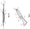
- FIG. 1A shows a wound site 20, with the distal end 17 of the oxygen delivery tubing 12 having the oxygen distribution tape 29 placed over or near the wound site 20.
- the tape 29 may be placed centrally on the wound site for optimal delivery of oxygen to the damaged tissue.
- the key is to saturate the wound with near 100% O 2 .
- a moisture absorbent dressing 14 is placed at the wound site covering the tape end of the oxygen delivery tubing 12 and wound site.
- moisture absorbent dressing is typical standard of care protocol for a difficult-to-heal wound.
- a reduced moisture vapor permeable dressing 16 covers the moisture absorbent dressing 14, tape end of tubing 12 and wound site 20, creating a restricted airflow enclosure.
- the reduced moisture vapor permeable dressing 16 is transparent and may be referred to as an occlusive dressing.
- the occlusive dressing traps the oxygen over the wound site to create and maintain oxygen rich environment.
- the local partial pressure of oxygen at the wound site 20 may be increased from a low range of 10 to 60 mm Hg to an oxygen rich environment range of 200 to 760 mm HG.
- the increased available oxygen is metabolized at the cellular level and will stimulate an increase in growth factors, epithelialization, granulation tissue, glycosaminoglycan production, and collagen synthesis. Because the system seeks to saturate the wound with 100% O 2 , the oxygen partial pressure at the wound site is communicated to the pressure monitoring system in the housing 13.
- the oxygen partial pressure sensor supplies data to the microprocessor 58 which controls the power flow (amperage) to the concentrator 11.
- the concentrator may increase or decrease the O 2 flow rate.
- the oxygen partial pressure sensor may be conductivity sensor, but other means for measuring this pressure may be utilized.
- FIG. 4 is a perspective view of a handset housing the major components of the present invention.
- FIG. 5 is a flow chart of the present invention.
- the monitor housing 13 draws in room air 50 with about 21% oxygen through the air inlet 40 by means of an electrochemical process.
- the room air passes through an ion exchange oxygen concentrator 11, which concentrates the oxygen level of the room air to create a mixture that is 99% pure oxygen.
- the power management system 52 controls the electrical current supplied to the ion exchange oxygen concentrator 11, thereby making the oxygen flow rate conform to the amount of current supplied to the ion exchange oxygen concentrator, i.e., increasing electrical current increases the electrochemical process and thereby increases the respective oxygen flow rate to the wound site 20 and decreasing the electrical current decreases the electrochemical process thereby decreasing the respective oxygen flow rate to the wound site.
- the power management system 52 includes lithium batteries (for example, 3.2 v) and a regulator which varies the current over a range from approximately 15 milliamps to approximately 150 milliamps, but more preferably, approximately 7 milliamps to approximately 70 milliamps. This range of current variation results in O 2 flow rates in the range of approximately 1.0 milliliters/hour to approximately 15.0 milliliters/hour and preferably approximately 3.0 milliliters/hour to approximately 10.0 milliliters/hour.
- lithium batteries for example, 3.2 v
- a regulator which varies the current over a range from approximately 15 milliamps to approximately 150 milliamps, but more preferably, approximately 7 milliamps to approximately 70 milliamps. This range of current variation results in O 2 flow rates in the range of approximately 1.0 milliliters/hour to approximately 15.0 milliliters/hour and preferably approximately 3.0 milliliters/hour to approximately 10.0 milliliters/hour.
- the concentrated O 2 then exits the housing through the oxygen delivery port 54.
- the proximal end 15 of the oxygen delivery tubing 12 is connected with an oxygen delivery port 54 with Leur-type locking fitting.
- the locking fitting is engaged to maintain an airtight seal with the tubing.
- a pressure sensor 30a or 19a and, where appropriate, a temperature sensor 32a/21a in the tubing 12 or 12a are in communication with the microprocessor 58.
- the microprocessor 58 communicates with the power management system 52, adjusting the oxygen flow rate (sensed at sensor 54) to the wound site per programmed algorithms to optimally meet changes in the patients oxygen wound healing requirements.
- FIGS. 6-6B the electrochemical oxygen generator/concentrator 11 is illustrated.
- the unique design of the concentrator has resulted in a sturdier pumping unit. There are times when the oxygen delivery tubing may become kinked or occluded. In prior art concentrators, the concentrator would rupture as a result of any slight backpressure. The concentrator of the present inventive system does not rupture when the discharge is occluded.
- the system provides alarms to notify the patient that the oxygen flow/pressure is out of range allowing the patient to check the delivery tubing. When a blockage of the oxygen flow occurs, an audible alarm will sound and a visual warning light will illuminate. The alarm will sound for two minutes.
- the alarm may be muted by pressing a mute button on the lower left-hand side of the monitoring housing. This will mute the audible alarm for fifteen minutes while the user troubleshoots the system.
- the tubing should be inspected for kinks or objects pressing on the tubing. Occlusion may occur at the wound site under the dressing.
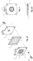
- FIG. 6 is a top plan view of concentrator 11 showing the cathode plate 70 overlaying the anode plate 72.
- FIG. 6A is a side elevation view of the concentrator 11.
- Each of the charged plates has a carbon backed metalized substrate with an 0.85 sq. inch titanium mesh plated on the woven fiber carbon membrane. This provides a complete coverage area for electrical conductance to a Nafion® oxygen transfer membrane.
- Nafion® is a registered trademark of DuPont and is a sulfonated tetrafluroethylene copolymer. Nafion® is well known in the art as a proton conductor for proton exchange membranes (PEM). A Nafion 212 membrane is preferred in the present invention.
- FIG. 6B is an exploded perspective view of the concentrator 11.
- the PEM membrane 74 is compressed fully between the cathode 70 and the anode 72 by torquing screw type fasteners.
- a gasket seal 76 may be utilized with flange bolting 78.
- a 304L stainless steel needle discharge valve 80 with viton seats is machined for attachment into the anode plate 72 using a viton O-ring (not shown).
- the preferred membrane 84 in the present invention is a Gore-Tex® fabric. (Gore-Tex® is the registered trademark of W.L. Gore & Associates.) Concentrated O 2 is discharged out discharge valve 80 which communicates with discharge 54 in housing 13.
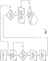
- FIG. 7 A firmware flow chart for the present invention is illustrated in FIG. 7 .
- the microprocessor 58 calibrates 92 all sensors and the PEM cell. Because every PEM cell and each sensor has its own particular functional characteristics, the present invention calibrates the sensors and cell to ensure precise flow rates.
- the microprocessor gets the desired 95 flow rate from the user.
- the microprocessor calculates current to output from the PEM to set desired flow rate 96.
- the microprocessor receives input from the flow rate sensor 54 and determines if the set flow rate has been reached 97, if not the processor again seeks to vary current to the sensors and the PEM cell. If the set flow rate is reached 97, then the microprocessor enters a PIO control mode 98.
- the flow rate is be adjusted based upon input from the pressure monitoring system and flow sensors.
- the microprocessor also displays the flow rate and the temperature (where appropriate) on the monitor display screen 68.
- the microprocessor continuously tests the actual flow rate to ensure that it is maintained 99 using a feedback loop which looks at variations in sensor and PEM cell efficiencies.
- a wound monitoring system is contemplated.
- Patient data and therapy commands are communicated to the device by the care giver or patient for processing by means of a data input key pad 64 and function control buttons 65.
- a data port 66 may be used to upload or download data.
- the monitoring system allows for collection and monitoring of key medical parameters to aid the caregiver in managing the patient care and potentially accelerate the healing process with improved access to more data.
- Available patient data and device functions are displayed and where appropriate are visually and audibly alarmed on the device function display screen 68.
- a digital camera 69 may also be utilized to aid the monitoring process visually tracking the wound closure progress.
Landscapes
- Health & Medical Sciences (AREA)
- Engineering & Computer Science (AREA)
- Life Sciences & Earth Sciences (AREA)
- Animal Behavior & Ethology (AREA)
- General Health & Medical Sciences (AREA)
- Public Health (AREA)
- Veterinary Medicine (AREA)
- Biomedical Technology (AREA)
- Heart & Thoracic Surgery (AREA)
- Anesthesiology (AREA)
- Hematology (AREA)
- Vascular Medicine (AREA)
- Dermatology (AREA)
- Pharmacology & Pharmacy (AREA)
- Chemical Kinetics & Catalysis (AREA)
- General Chemical & Material Sciences (AREA)
- Medicinal Chemistry (AREA)
- Nuclear Medicine, Radiotherapy & Molecular Imaging (AREA)
- Organic Chemistry (AREA)
- Chemical & Material Sciences (AREA)
- Bioinformatics & Cheminformatics (AREA)
- Pharmaceuticals Containing Other Organic And Inorganic Compounds (AREA)
- External Artificial Organs (AREA)
- Surgical Instruments (AREA)
- Measurement Of The Respiration, Hearing Ability, Form, And Blood Characteristics Of Living Organisms (AREA)
- Separation Using Semi-Permeable Membranes (AREA)
Description
- This invention relates to tissue treatment systems, specifically to tissue oxygenation systems for accelerating the healing of damaged tissue and promoting tissue viability. The present low dose tissue oxygenation system is intended for use with wound dressings to treat the following: skin ulcerations due to diabetes, venous stasis, post surgical infections and gangrenous lesions; pressure ulcers; infected residual limbs; skin grafts; burns; and frostbite.
- When tissue is damaged a wound results and healing process begins. The term "wound" includes, but is not limited to, chronic, traumatic, and surgically created wounds. Optimal metabolic function of these cells to repopulate the wound requires that oxygen be available for all phases of wound healing. The more layers of tissue that are damaged the greater the risk for complications to occur in the wound healing process.
- Difficult-to-heal wounds encounter barriers to the wound healing process and typically experience delays in one or more of the phases of wound healing. One of the most common contributing factors to venous leg ulcers, diabetic foot ulcers and pressure ulcers experiencing delays in the healing process is the problem of chronic wound ischemia. Chronic wound ischemia is a pathological condition that restricts blood supply, oxygen delivery and blood request for adequate oxygenation of tissue, inhibiting normal wound healing.
- In practice the standard of care for treating difficult-to-heal wounds typically involves the use of an advanced wound dressing or combination of advanced wound dressings providing a dressing treatment system. An advanced dressing is positioned on the wound site or on the wound site and the surrounding intact skin providing a wound site enclosure. An advanced wound dressing is typically comprised of materials having properties for promoting moist wound healing, managing wound exudate and helping control wound bioburden. The typical material components in combination further include properties for providing limited moisture vapor permeability. The lower the dressing's moisture vapor permeability or more occlusive the dressing the lower the amount of ambient air and the respective lower amount of oxygen is thereby available to the wound bed. 100% oxygen exerts a partial pressure of 760 mm Hg. Ambient air is comprised of about 21% oxygen thereby exerting a partial pressure of oxygen at about 159 mm Hg. A typical advanced wound dressing or wound dressing system comprised of lower moisture vapor permeable materials impacts the available oxygen for the wound site thereby limiting the partial pressure of oxygen at the enclosed wounds site at about 10 mm Hg to 60 mm Hg. Fresh air is provided to the wound site only when the dressing is changed. A dressing may remain covering the wound site for up to seven days before a dressing change is required. The moisture vapor permeability property of an advanced wound dressing providing a reduced oxygen wound environment thereby works against the optimal metabolic function of cells to repopulate the wound which requires that oxygen be available for all phases of wound healing.
- Prior art methods of tissue oxygenation for difficult-to-heal wounds include topical hyperbaric oxygen applied intermittently or continuously. Intermittent topical hyperbaric oxygen is a method of tissue oxygenation comprising of a sealed extremity or partial body chamber and a connected source of high flow pure oxygen whereby the affected limb or affected body area is positioned in a sealed extremity chamber or partial body chamber so that the oxygen source supplying the chamber is providing the patient topically up to 100% oxygen at flow rates that may exceed 300 liters per hour pressurizing the interior of the chamber up to 1.05% normal atmospheric pressure thereby increasing the available oxygen for cellular processing at affected wound site. During the oxygen application, the partial pressure of oxygen exerted inside the topical or partial body chamber may attain 798 mm Hg. Topical hyperbaric oxygen is applied for about 90 minutes. Prior art also teaches a plurality of methods to apply topically hyperbaric oxygen intermittently. A partial body chamber for treating sacral wounds has been described in
U.S. Pat. No. 4,328,799 to LoPiano (1980) whereby oxygen is applied from a stationary supply tank into the interior of the chamber through connected tubing. A similar method of applying topical hyperbaric oxygen is described inU.S. Pat. No. 5,478,310 to Dyson-Cantwell (1995) whereby oxygen is applied from a stationary supply tank into the interior of the disposable extremity chamber through connected tubing. These and similar methods of applying intermittent topical hyperbaric oxygen are restrictive, cumbersome, can only supply oxygen to the affected area intermittently with no systemic application, and can only be applied with a minimal increase in atmospheric pressure (about 5%). Therefore the effect of the oxygen therapy on the wound can be minimal which is evidenced by the lack of commercial success from topical hyperbaric oxygen extremity chambers. - Both
U.S. Pat. No. 5,578,022 to Scherson (1996) andU.S. Pat. No. 5,788,682 to Maget (1998) describe disposable devices utilizing transmission of gases in ionic form through ion specific membranes to apply supplemental oxygen directly to the wound bed. These devices are described as battery powered, disposable, oxygen producing bandages and methods that are applied directly over the wound. They both include electrochemical oxygen generation using variations of the same 4 electron formula originally developed for NASA inU.S. Pat. No. 3,489,670 to Maget (1970). The amount of oxygen that can be applied to the wound is typically 3 milliliters per hour. Specific oxygen flow rates are generated by means of corresponding specific, preselected battery sizes and specific prescribed amperages. Prior art describes disposable devices are either "on or off." The prior art describes disposable devices without means to sense temperature changes in the wound site oxygen environment. Prior art does not provide a means to deliver a varying (adjustable) oxygen flow rate without requiring the patient to obtain and apply a new device with a new battery having a specific amperage. Additional limitations are also associated with the use of a fixed non-variable oxygen flow rate. -
WO03049660 (A1 -
US5855570 (A ) describes a portable, self-contained device for the topical application of oxygen to promote the healing of skin wounds. The device is comprised of a wound dressing that incorporates an electrochemical, chemical, or thermal means of generating high purity oxygen. The device can regulate the supply of oxygen to an area above the wound at various concentrations, pressures and dosages. -
EP2244746 (A2 ) is state of the art under Article 54(3) EPC only. It describes apparatus and methods to treat skin defects including a pump with reservoirs for a pressurization gas and a fluid, the fluid loaded at a factory and sealed or filled at point of use through a valve, septum, or the like. Upon activation, the pump generates a gas introduced into the gas reservoir, a movable wall of which displaces a movable wall of a fluid source, thus dispensing the fluid into the dressing to spread throughout irrespective of orientation of the dressing, maintaining a transport fluid (e.g. carrier) in the dressing and in contact with a skin defect being treated. Delivery may be periodic, constant, programmatically controlled, or manual. A dressing may maintain intimate contact, a transport fluid, and a controllable concentration of active ingredient against a skin defect. - No prior art low dose tissue oxygenation device provides continuous oxygen adjustability to a patient's wound(s) creating a controlled hyperoxia and hypoxia wound environment for damaged tissue to accelerate wound healing and promote tissue viability. Specifically, nothing in the prior art teaches continuous oxygen adjustability based on actual flow rate, partial pressures at the wound site, and, where necessary, temperatures at the wound site.
- The invention is an improved low dose tissue oxygenation device and wound monitoring system according to the appended claims. The present invention generally comprises an oxygen delivery, micro-bore, tube for placement at or near the wound bed and a wound dressing covering the tubing and wound site for restricted air flow enclosure. The tubing may have multiple holes at or near the distal end of the tubing. The tubing may include a generally flat, flexible, oxygen permeable tape or membrane section attached at the distal end of the tube. The tubing may be flexible with a kink resistant inner lumen. The tubing may have a temperature sensor. The tubing may include a partial pressure of oxygen sensor. The proximal end of the tubing is connected to a source of oxygen. The proximal end of the tubing may have a port Leur-type locking mechanism for an airtight seal during application of the oxygen and for removal from the oxygen source during application a dressing. A source of oxygen is in communication with the proximal and distal ends of the tube. A source of oxygen is an electrochemical oxygen concentrator supplied by alternating or direct current, a power management device and its power management protocol. The variable electrochemical oxygen concentrator is used in accordance with the present invention by varying the oxygen flow rate to meet varying target parameters at the wound site. The oxygen flow rate is adjusted by a system that periodically or continuously monitors the wound bed pressure and, where appropriate, the temperature environment. Additionally, the system monitors the tubing pressure and adjusts the oxygen flow rate in accordance to target set points. Adjusting oxygen flow in response to monitored changes in wound site oxygen and target oxygen pressure and, where appropriate, temperature protocols provides a controlled hyperoxia wound environment which may shorten the healing process. The present monitoring system further provides an alarm when the pressure or flow rates have gone out of range.
- Excessive oxygen pressure (i.e., greater than 22mm of Hg) can occlude arterial circulation leading to decreased local tissue circulation and local tissue damage. Therefore, the device design addresses how the device controls oxygen pressure and pressures do not exceed a safe limit. Unlike a typical topical oxygen chamber for extremities, the present system does not create a sealed, oxygen rich environment inside a chamber in which a patient's limb is inserted. Instead, oxygen is generate by a Proton Exchange Membrane within the portable device and delivered to the wound site via micro-bore tubing at a rate of 3 ml/hr to 10 ml/hr. Because the wound site is covered only by occlusive wound dressing instead of the entire limb being inserted into a sealed chamber, oxygen pressure at the site and around the limb never exceeds normal atmospheric pressure.
- In some embodiments, the device may have a backlight display terminal or touch screen liquid crystal display, a data input key pad or device function control buttons, a wound temperature monitoring system, a battery and oxygen pressure alarm system, a digital camera, a patient data input and memory system and/or a data port or wireless data access.
- A more complete understanding of the present disclosure and advantages thereof may be acquired by referring to the following description taken in conjunction with the accompanying figures, wherein:
-
FIG. 1 is a perspective view of an embodiment of a tissue oxygenation system of the present invention. -
FIG. 1A is a cross section view of a wound site showing a distal end of a oxygen delivery tube of the present invention -
FIG. 2 is a side perspective view of the distal end of an embodiment of the tubing of the present invention showing a generally flat, flexible, oxygen-permeable tape or membrane section affixed to the tubing. -
FIG. 2A is an end view of another embodiment of the tubing of the present invention. -
FIG. 3 is side elevation view of the distal end of the oxygen delivery tubing of the embodiment ofFIG. 2A of the present inventionFIG. 4 is a perspective view of a handset of the present invention. -
FIG. 5 is a flow chart illustrating the process of the present invention. -
FIG. 6 is a top plan view of the electrolyzer/concentrator of the present invention. -
FIG. 6A is a side elevation plan view of the electrolyzer ofFIG. 6 . -
FIG. 6B is an exploded perspective view of the eletrolyzer ofFIG. 6 . -
FIG. 7 is a processor firmware flow chart of the present invention. - A preferred embodiment of the present invention, tissue oxygenation system for the healing of damaged tissue and to promote tissue viability, will now be described in detail with reference to the figures.
-
FIG. 1 is a perspective view of several primary components of the present invention according to the preferred embodiment. The present invention includes amonitoring unit 10, anelectrochemical oxygen concentrator 11,oxygen delivery tubing 12, moisture absorbent dressing 14, andvapor dressing 16. Theoxygen delivery tubing 12 is connected at theproximal end 15 of the long, kink resistant tubing to themonitoring unit 10. Themonitoring unit 10 has a small, lightweight housing which is portable and may be discretely worn by the patient in a pocket or attached to a belt. - The
monitoring unit 10 includes within the housing 13 a microprocessor 58 (seeFIGS. 5 and7 ), apower management system 52,pressure 30a and, where appropriate,temperature 32a sensor interface(s), aflow rate sensor 54, aninput port 62 and auser entry port 66. Theelectrochemical oxygen concentrator 11 is disposed within thehousing 13. The microprocessor 58 functions to control power, collect various readings from the flow, pressure, and temperature sensors and controls ionic purification of room air by the electrochemical oxygen concentrator for delivery to the tubing, and controls the informational display on themonitoring unit 10. Preferably, the microprocessor 58 is capable of receiving data through the user entry port and the input port, including information related to specific patients and reprogramming information if there is a system malfunction with the device. - As may be further seen in
FIGS. 1A and 2 , thedistal end 17 of thetubing 12 may have a soft, flexible, oxygen permeable tape ormembrane section 29 placed on or near the damaged tissue or woundsite 20 of a patient'slimb 19 covered with a moisture absorbent dressing 14 and further covered by a reduced vapor pressure, permeable,occlusive dressing 16. - In a first embodiment, oxygen is delivered to the
wound site 20 through a kink-resistant tube 12 connected at theproximal end 15 to the outlet of the oxygen concentrator at the monitor unit housing. On thedistal end 17 of thetubing 12 is connected soft, flexible oxygen-permeable flat tape ormembrane 29. Extending through the lumen of the tube areseveral sensor wires partial pressure sensor 30a disposed at the wound site to the microprocessor 58 as would be understood by one of ordinary skill in the art. In other embodiments, the sensor wires may be eliminated and pressure, flow rate, and even temperature may be measured within the monitor unit housing at the outlet of the oxygen concentrator. - Alternatively,
tubing 12a (FIG. 2A ) preferably may have several lumens,pressure 21 andtemperature 19 sensors, and other such sensors as may be required to effectively monitor wound treatment, disposed therein. Specifically,FIG. 2A illustrates an end view of thetubing 12a, and depicts a tubing with a length capable of connecting to the output side ofelectrochemical oxygen concentrator 11 housed withinmonitoring unit 10. Such tubing lengths allow the monitoring unit to be worn discretely and continuously deliver oxygen to thewound site 20. An inner lumen, or bore 18a, of the tubing is a star like configuration to prevent kinking of the tubing and still allows oxygen flow if bent. An oxygenpartial pressure sensor 19a at or near the wound site may be disposed within the tubing and be in communication with a pressure monitoring system allowing for oxygen flow rate adjustment, visual pressure display, and out of range alarm. Atemperature sensor 21a may also be disposed within the tubing at thewound site 20 and is in communication with a temperature monitoring system allowing for visual display of temperature, an out of range alarm, and allowing for oxygen adjustment via the microprocessor 58 as is appropriate. -
FIG. 3 is a side view of the distal end ofalternative tubing 12a, which includes a plurality ofholes 23 formed along the side of the distal end of the tubing to aid in the delivery of oxygen to the wound. In use, the oxygen flows F through the tubing to the wound site and may enter the wound bed through themultiple holes 23. The oxygen may also flow through the distal end of star shapedlumen 18a, however, the multiple holes at the distal end of the tubing allow for improved flow of oxygen to thewound site 20. -
FIG. 1A shows awound site 20, with thedistal end 17 of theoxygen delivery tubing 12 having theoxygen distribution tape 29 placed over or near thewound site 20. Thetape 29 may be placed centrally on the wound site for optimal delivery of oxygen to the damaged tissue. The key is to saturate the wound with near 100% O2. A moisture absorbent dressing 14 is placed at the wound site covering the tape end of theoxygen delivery tubing 12 and wound site. One skilled in the art will appreciate that moisture absorbent dressing is typical standard of care protocol for a difficult-to-heal wound. A reduced moisture vapor permeable dressing 16 covers the moisture absorbent dressing 14, tape end oftubing 12 and woundsite 20, creating a restricted airflow enclosure. Preferably the reduced moisture vaporpermeable dressing 16 is transparent and may be referred to as an occlusive dressing. The occlusive dressing traps the oxygen over the wound site to create and maintain oxygen rich environment. The local partial pressure of oxygen at thewound site 20 may be increased from a low range of 10 to 60 mm Hg to an oxygen rich environment range of 200 to 760 mm HG. The increased available oxygen is metabolized at the cellular level and will stimulate an increase in growth factors, epithelialization, granulation tissue, glycosaminoglycan production, and collagen synthesis. Because the system seeks to saturate the wound with 100% O2, the oxygen partial pressure at the wound site is communicated to the pressure monitoring system in thehousing 13. The oxygen partial pressure sensor supplies data to the microprocessor 58 which controls the power flow (amperage) to theconcentrator 11. The concentrator may increase or decrease the O2 flow rate. The oxygen partial pressure sensor may be conductivity sensor, but other means for measuring this pressure may be utilized. -
FIG. 4 is a perspective view of a handset housing the major components of the present invention.FIG. 5 is a flow chart of the present invention. - As shown in
FIGS. 4 and5 , in use, themonitor housing 13 draws inroom air 50 with about 21% oxygen through theair inlet 40 by means of an electrochemical process. The room air passes through an ionexchange oxygen concentrator 11, which concentrates the oxygen level of the room air to create a mixture that is 99% pure oxygen. Thepower management system 52 controls the electrical current supplied to the ionexchange oxygen concentrator 11, thereby making the oxygen flow rate conform to the amount of current supplied to the ion exchange oxygen concentrator, i.e., increasing electrical current increases the electrochemical process and thereby increases the respective oxygen flow rate to thewound site 20 and decreasing the electrical current decreases the electrochemical process thereby decreasing the respective oxygen flow rate to the wound site. It should be noted that thepower management system 52 includes lithium batteries (for example, 3.2 v) and a regulator which varies the current over a range from approximately 15 milliamps to approximately 150 milliamps, but more preferably, approximately 7 milliamps to approximately 70 milliamps. This range of current variation results in O2 flow rates in the range of approximately 1.0 milliliters/hour to approximately 15.0 milliliters/hour and preferably approximately 3.0 milliliters/hour to approximately 10.0 milliliters/hour. - The concentrated O2 then exits the housing through the
oxygen delivery port 54. Theproximal end 15 of theoxygen delivery tubing 12 is connected with anoxygen delivery port 54 with Leur-type locking fitting. The locking fitting is engaged to maintain an airtight seal with the tubing. - As illustrated in
FIGS. 2 and5 , apressure sensor temperature sensor 32a/21a in thetubing power management system 52, adjusting the oxygen flow rate (sensed at sensor 54) to the wound site per programmed algorithms to optimally meet changes in the patients oxygen wound healing requirements. - Turning to
FIGS. 6-6B , the electrochemical oxygen generator/concentrator 11 is illustrated. The unique design of the concentrator has resulted in a sturdier pumping unit. There are times when the oxygen delivery tubing may become kinked or occluded. In prior art concentrators, the concentrator would rupture as a result of any slight backpressure. The concentrator of the present inventive system does not rupture when the discharge is occluded. The system provides alarms to notify the patient that the oxygen flow/pressure is out of range allowing the patient to check the delivery tubing. When a blockage of the oxygen flow occurs, an audible alarm will sound and a visual warning light will illuminate. The alarm will sound for two minutes. The alarm may be muted by pressing a mute button on the lower left-hand side of the monitoring housing. This will mute the audible alarm for fifteen minutes while the user troubleshoots the system. The tubing should be inspected for kinks or objects pressing on the tubing. Occlusion may occur at the wound site under the dressing. -
FIG. 6 is a top plan view ofconcentrator 11 showing thecathode plate 70 overlaying theanode plate 72.FIG. 6A is a side elevation view of theconcentrator 11. - Each of the charged plates has a carbon backed metalized substrate with an 0.85 sq. inch titanium mesh plated on the woven fiber carbon membrane. This provides a complete coverage area for electrical conductance to a Nafion® oxygen transfer membrane. Nafion® is a registered trademark of DuPont and is a sulfonated tetrafluroethylene copolymer. Nafion® is well known in the art as a proton conductor for proton exchange membranes (PEM). A Nafion 212 membrane is preferred in the present invention.
-
FIG. 6B is an exploded perspective view of theconcentrator 11. ThePEM membrane 74 is compressed fully between thecathode 70 and theanode 72 by torquing screw type fasteners. To provide proper sealing of the concentrator, agasket seal 76 may be utilized with flange bolting 78. A 304L stainless steelneedle discharge valve 80 with viton seats is machined for attachment into theanode plate 72 using a viton O-ring (not shown). - Electrical contact and transfer to the plates is accomplished by attaching a copper strip to the titanium mesh substrate. The compressive force applied provides the necessary adhesion to the surfaces of the two metals. The strips are then attached to the charge plates with epoxy.
- Ambient air enters the concentrator through
inlet 82 which is covered by apolarized membrane 84 which allows water vapor to pass in one direction only and maintain the encapsulation of other gases (mainly hydrogen). Thepreferred membrane 84 in the present invention is a Gore-Tex® fabric. (Gore-Tex® is the registered trademark of W.L. Gore & Associates.) Concentrated O2 is discharged outdischarge valve 80 which communicates withdischarge 54 inhousing 13. - A firmware flow chart for the present invention is illustrated in
FIG. 7 . When themonitoring unit 10 is started or powered up 90, the microprocessor 58 calibrates 92 all sensors and the PEM cell. Because every PEM cell and each sensor has its own particular functional characteristics, the present invention calibrates the sensors and cell to ensure precise flow rates. - If the calibration is successful 94, then the microprocessor gets the desired 95 flow rate from the user. The microprocessor calculates current to output from the PEM to set desired
flow rate 96. The microprocessor receives input from theflow rate sensor 54 and determines if the set flow rate has been reached 97, if not the processor again seeks to vary current to the sensors and the PEM cell. If the set flow rate is reached 97, then the microprocessor enters aPIO control mode 98. The flow rate is be adjusted based upon input from the pressure monitoring system and flow sensors. The microprocessor also displays the flow rate and the temperature (where appropriate) on themonitor display screen 68. - In the proportional control mode, the microprocessor continuously tests the actual flow rate to ensure that it is maintained 99 using a feedback loop which looks at variations in sensor and PEM cell efficiencies.
- In another disclosure a wound monitoring system is contemplated. Patient data and therapy commands are communicated to the device by the care giver or patient for processing by means of a data input
key pad 64 andfunction control buttons 65. Adata port 66 may be used to upload or download data. The monitoring system allows for collection and monitoring of key medical parameters to aid the caregiver in managing the patient care and potentially accelerate the healing process with improved access to more data. Available patient data and device functions are displayed and where appropriate are visually and audibly alarmed on the devicefunction display screen 68. Adigital camera 69 may also be utilized to aid the monitoring process visually tracking the wound closure progress.
Claims (7)
- A tissue oxygenation system for aiding in the healing of damaged tissue comprising:a monitoring unit (10) including within a housing (13):an electrochemical oxygen concentrator (11) for generating oxygen;a microprocessor (58) for variably adjusting oxygen flow from said concentrator (11) to said damaged tissue;a pressure monitoring system configured to output pressure information to said microprocessor (58),a power management system (52) controlled by said microprocessor (58) and configured to deliver variable power to the concentrator (11) to adjust the oxygen flow rate;an oxygen partial pressure sensor interface (30a);a flow rate sensor (54) that is coupled to the microprocessor (58), wherein the microprocessor (58) is operable to receive oxygen flow rate information from the flow rate sensor (54); andan input port (62), a user entry port (66) and a display screen (68);andtubing (12), having distal and proximal ends and connecting the concentrator (11) to receive said oxygen and deliver said oxygen to said damaged tissue (20),wherein said proximal end of the tubing is removably connected to said concentrator and the distal end of the tubing is placed on or near said damaged tissue (20);a moisture absorbent dressing (14, 16) positioned over said distal end of said tubing (12); and a reduced moisture vapor permeable dressing system positioned over and covering said moisture absorbent dressing, said distal end of said tubing and said damaged tissue (20) thereby forming a restricted airflow enclosure.
- The tissue oxygenation system of claim 1, wherein said distal end of said tubing (12) comprises a generally flat, oxygen-permeable tape section (29).
- The tissue oxygenation system of claim 1, wherein said microprocessor (58) is capable of receiving user input data.
- The tissue oxygenation system of claim 1, further comprising a temperature monitoring system outputting data from said damaged tissue to said microprocessor (58).
- The tissue oxygenation system of claim 1, wherein said microprocessor (58) regulates the oxygen flow rate delivered to said damaged tissue using any combination of temperature data, pressure data, and user input data.
- The tissue oxygenation system of claim 1, wherein the pressure monitoring system is configured to provide an alarm when the pressure or oxygen flow rates are out of range.
- The tissue oxygenation system of claim 6, wherein the out of range alarm is a visual warning light and audible alarm.
Applications Claiming Priority (2)
| Application Number | Priority Date | Filing Date | Title |
|---|---|---|---|
| US12/288,873 US8287506B2 (en) | 2007-10-26 | 2008-10-24 | Apparatus and methods for controlling tissue oxygenation for wound healing and promoting tissue viability |
| PCT/US2009/002523 WO2010047732A1 (en) | 2008-10-24 | 2009-04-23 | Apparatus and methods for controlling tissue oxygenation for wound healing and promoting tissue viability |
Publications (3)
| Publication Number | Publication Date |
|---|---|
| EP2340001A1 EP2340001A1 (en) | 2011-07-06 |
| EP2340001A4 EP2340001A4 (en) | 2016-03-02 |
| EP2340001B1 true EP2340001B1 (en) | 2020-06-03 |
Family
ID=40583785
Family Applications (1)
| Application Number | Title | Priority Date | Filing Date |
|---|---|---|---|
| EP09822290.4A Active EP2340001B1 (en) | 2008-10-24 | 2009-04-23 | Apparatus and methods for controlling tissue oxygenation for wound healing and promoting tissue viability |
Country Status (7)
| Country | Link |
|---|---|
| US (3) | US8287506B2 (en) |
| EP (1) | EP2340001B1 (en) |
| JP (1) | JP5579188B2 (en) |
| CN (1) | CN102202618B (en) |
| AU (1) | AU2009307077B2 (en) |
| CA (1) | CA2681155C (en) |
| WO (1) | WO2010047732A1 (en) |
Families Citing this family (44)
| Publication number | Priority date | Publication date | Assignee | Title |
|---|---|---|---|---|
| ATE489062T1 (en) * | 2003-09-12 | 2010-12-15 | Z Medica Corp | PARTIALLY HYDROGENATED HEMOSTATIC AGENT |
| US20060178609A1 (en) | 2005-02-09 | 2006-08-10 | Z-Medica, Llc | Devices and methods for the delivery of molecular sieve materials for the formation of blood clots |
| JP2008531498A (en) | 2005-02-15 | 2008-08-14 | バージニア コモンウェルス ユニバーシティ | Mineral technology (MT) for emergency hemostasis and treatment of acute wounds and chronic ulcers |
| US8938898B2 (en) * | 2006-04-27 | 2015-01-27 | Z-Medica, Llc | Devices for the identification of medical products |
| US8202532B2 (en) * | 2006-05-26 | 2012-06-19 | Z-Medica Corporation | Clay-based hemostatic agents and devices for the delivery thereof |
| US7968114B2 (en) * | 2006-05-26 | 2011-06-28 | Z-Medica Corporation | Clay-based hemostatic agents and devices for the delivery thereof |
| US7604819B2 (en) | 2006-05-26 | 2009-10-20 | Z-Medica Corporation | Clay-based hemostatic agents and devices for the delivery thereof |
| US20080317831A1 (en) * | 2007-06-21 | 2008-12-25 | Denny Lo | Hemostatic sponge and method of making the same |
| WO2009032884A1 (en) * | 2007-09-05 | 2009-03-12 | Z-Medica Corporation | Wound healing with zeolite-based hemostatic devices |
| US8287506B2 (en) | 2007-10-26 | 2012-10-16 | Electrochemical Oxygen Concepts, Inc. | Apparatus and methods for controlling tissue oxygenation for wound healing and promoting tissue viability |
| US10226610B2 (en) | 2007-10-26 | 2019-03-12 | Electrochemical Oxygen Concepts, Inc. | Apparatus and methods for controlling tissue oxygenation for wound healing and promoting tissue viability |
| GB2470358B (en) * | 2009-05-18 | 2014-05-14 | Inotec Amd Ltd | Hyperbaric dressing and method |
| US10091985B2 (en) * | 2009-06-18 | 2018-10-09 | Giner, Inc. | Perfusing an organ with an in situ generated gas |
| US9357764B2 (en) * | 2009-06-18 | 2016-06-07 | Giner, Inc. | System for fluid perfusion of biological matter comprising tissue |
| US20110015565A1 (en) * | 2009-07-15 | 2011-01-20 | Hursey Francis X | Gas dispenser with therapeutic agent |
| EP2519297A4 (en) | 2009-12-31 | 2013-08-21 | Univ Ohio | SYSTEMS AND METHODS FOR PROMOTING HEALING |
| US8858969B2 (en) | 2010-09-22 | 2014-10-14 | Z-Medica, Llc | Hemostatic compositions, devices, and methods |
| US10383771B2 (en) | 2011-11-28 | 2019-08-20 | Hyposkin Aps | System for reduced scarring of wounds |
| GB201206907D0 (en) * | 2012-04-19 | 2012-06-06 | Inotec Amd Ltd | Oxygen distributor |
| WO2013191836A1 (en) | 2012-06-22 | 2013-12-27 | Z-Medica, Llc | Hemostatic devices |
| WO2014055989A1 (en) | 2012-10-05 | 2014-04-10 | University Of Southern California | Implantable oxygenator with self-contained electrolyte |
| EP2759310B2 (en) | 2013-01-28 | 2023-11-08 | Mölnlycke Health Care AB | Suction device |
| EP2956101B1 (en) | 2013-02-12 | 2018-05-16 | Electrochemical Oxygen Concepts, Inc. | Dressing for wound treatment |
| CA2894184C (en) | 2013-06-29 | 2020-07-14 | Vaporox, Inc. | Medical treatment system and method of use |
| CN103393402B (en) * | 2013-07-01 | 2016-06-29 | 西安交通大学 | A kind of wound surface dressing binder pressure monitor of Portable burn and wound |
| CN105792775B (en) | 2013-09-24 | 2019-02-19 | 吉纳生命科学公司 | System for gas treatment of cellular implants |
| CA2954877C (en) | 2014-03-19 | 2023-05-09 | Wound Care, Inc. | Portable medical treatment system and method of use |
| US9770369B2 (en) | 2014-08-08 | 2017-09-26 | Neogenix, Llc | Wound care devices, apparatus, and treatment methods |
| US10245392B2 (en) * | 2014-08-08 | 2019-04-02 | Neogenix, Llc | Oxygen concentrating device, wound care apparatus, and treatment methods |
| US11511055B2 (en) * | 2014-08-08 | 2022-11-29 | Neogenix, Llc | Oxygen concentrating device, wound care apparatus, and treatment methods |
| AU2016256436B2 (en) * | 2015-04-28 | 2020-10-22 | Convatec Technologies Inc. | Antibacterial nanofibres |
| CN104939796A (en) * | 2015-05-18 | 2015-09-30 | 中国人民解放军第四军医大学 | Visual pocket used for skin grafting |
| CN104840173A (en) * | 2015-05-18 | 2015-08-19 | 中国人民解放军第四军医大学 | Heat insulation cashmere material for skin-grafting piece visual bag |
| CN104840174A (en) * | 2015-05-18 | 2015-08-19 | 中国人民解放军第四军医大学 | Visible skin-grafting instrument |
| EP3361950A4 (en) * | 2015-10-13 | 2019-03-20 | HyperMed Imaging, Inc. | COMPACT LIGHT SENSORS FOR SURGICAL APPLICATIONS AND SHOCK DETECTION |
| WO2017100320A1 (en) | 2015-12-07 | 2017-06-15 | Electrochemical Oxygen Concepts, Inc. | Apparatus and methods for controlling tissue oxygenation for wound healing and promoting tissue viability |
| RU2019114817A (en) | 2016-11-15 | 2020-11-16 | Джинер Лайф Сайенс, Инк. | DEVICE FOR PERCUTANEOUS DIFFUSION OF GASES SUITABLE FOR USE WITH SUBCUTANEOUS IMPLANT |
| WO2018093940A1 (en) | 2016-11-15 | 2018-05-24 | Giner, Inc. | Self-regulating electrolytic gas generator and implant system comprising the same |
| WO2019222704A1 (en) | 2018-05-17 | 2019-11-21 | Giner Life Sciences, Inc. | Electrolytic gas generator with combined lead and gas port terminals |
| US11432965B2 (en) * | 2018-10-05 | 2022-09-06 | Deborah Kantor | Medical bandage for the head, a limb or a stump |
| US11504466B2 (en) | 2019-04-08 | 2022-11-22 | Jeffrey Hegg | Medical gauze and gas flow assembly and method of applying a medical gauze with gas flow on a wound |
| CA3135668A1 (en) | 2019-04-15 | 2020-10-22 | Electrochemical Oxygen Concepts, Inc. | Wound oxygen treatment system |
| WO2022104246A1 (en) | 2020-11-16 | 2022-05-19 | Vaporox, Inc. | Multistage vaporizer for medical treatment system |
| CN118203500A (en) * | 2024-01-18 | 2024-06-18 | 中国人民解放军南部战区总医院 | Intelligent control system of local hyperbaric oxygen therapy package |
Family Cites Families (23)
| Publication number | Priority date | Publication date | Assignee | Title |
|---|---|---|---|---|
| US3489670A (en) * | 1964-07-29 | 1970-01-13 | Gen Electric | Process for gas purification |
| JPS62129052A (en) * | 1985-11-29 | 1987-06-11 | ユニコロイド株式会社 | Wound covering material |
| US5578022A (en) * | 1995-04-12 | 1996-11-26 | Scherson; Daniel A. | Oxygen producing bandage and method |
| US5788682A (en) * | 1995-04-28 | 1998-08-04 | Maget; Henri J.R. | Apparatus and method for controlling oxygen concentration in the vicinity of a wound |
| US6071267A (en) * | 1998-02-06 | 2000-06-06 | Kinetic Concepts, Inc. | Medical patient fluid management interface system and method |
| US6458109B1 (en) | 1998-08-07 | 2002-10-01 | Hill-Rom Services, Inc. | Wound treatment apparatus |
| US6010317A (en) * | 1998-09-01 | 2000-01-04 | Baxter International Inc. | Electrochemical cell module having an inner and an outer shell with a nested arrangement |
| US6171368B1 (en) * | 1998-11-06 | 2001-01-09 | Med-E-Cell | Gas extraction from closed containers |
| ATE372124T1 (en) * | 2001-02-01 | 2007-09-15 | Hydron Technologies Inc | COMPOSITION AND METHOD FOR PERCUTANE SUPEROXYGENATION |
| US7429252B2 (en) * | 2001-12-12 | 2008-09-30 | Ogenix Corporation | Oxygen producing device for woundcare |
| ES2372634T3 (en) * | 2001-12-12 | 2012-01-25 | Neogenix, Llc | OXYGEN PRODUCER DEVICE FOR WOUND CARE. |
| US7322971B2 (en) | 2003-02-07 | 2008-01-29 | Alfred E. Mann Institute For Biomedical Engineering At The University Of Southern California | Surgical drain with sensors for monitoring internal tissue condition by transmittance |
| US7014630B2 (en) * | 2003-06-18 | 2006-03-21 | Oxyband Technologies, Inc. | Tissue dressing having gas reservoir |
| US8100956B2 (en) * | 2006-05-09 | 2012-01-24 | Thermotek, Inc. | Method of and system for thermally augmented wound care oxygenation |
| US7316857B1 (en) * | 2004-06-28 | 2008-01-08 | Swanson Steven T | Miniature electrochemical gas generator and power source |
| US20060225737A1 (en) * | 2005-04-12 | 2006-10-12 | Mr. Mario Iobbi | Device and method for automatically regulating supplemental oxygen flow-rate |
| CA2606508C (en) * | 2005-05-10 | 2014-08-12 | Ogenix Corporation | Novel portable electrochemical devices for dual action wound healing |
| US8640696B2 (en) | 2005-07-07 | 2014-02-04 | Ric Investments Llc | System and method for determining humidity in a respiratory treatment system |
| US7837673B2 (en) * | 2005-08-08 | 2010-11-23 | Innovative Therapies, Inc. | Wound irrigation device |
| US8808754B2 (en) | 2006-06-29 | 2014-08-19 | Systagenix Wound Management (Us), Inc. | Methods for the treatment of wounds |
| US8287506B2 (en) * | 2007-10-26 | 2012-10-16 | Electrochemical Oxygen Concepts, Inc. | Apparatus and methods for controlling tissue oxygenation for wound healing and promoting tissue viability |
| US20090216204A1 (en) * | 2008-02-27 | 2009-08-27 | Sai Bhavaraju | Auto-replenishing, wound-dressing apparatus and method |
| EP2782615B1 (en) | 2011-11-23 | 2016-10-19 | KCI Licensing, Inc. | Reduced-pressure systems, methods, and devices for simultaneously treating a plurality of tissue sites |
-
2008
- 2008-10-24 US US12/288,873 patent/US8287506B2/en active Active
-
2009
- 2009-04-23 CN CN200980142540.0A patent/CN102202618B/en active Active
- 2009-04-23 JP JP2011533156A patent/JP5579188B2/en active Active
- 2009-04-23 WO PCT/US2009/002523 patent/WO2010047732A1/en not_active Ceased
- 2009-04-23 US US12/738,905 patent/US9730838B2/en active Active
- 2009-04-23 EP EP09822290.4A patent/EP2340001B1/en active Active
- 2009-04-23 AU AU2009307077A patent/AU2009307077B2/en active Active
- 2009-04-23 CA CA2681155A patent/CA2681155C/en active Active
-
2017
- 2017-07-06 US US15/642,833 patent/US10632018B2/en active Active
Non-Patent Citations (1)
| Title |
|---|
| None * |
Also Published As
| Publication number | Publication date |
|---|---|
| EP2340001A4 (en) | 2016-03-02 |
| US20090112170A1 (en) | 2009-04-30 |
| WO2010047732A1 (en) | 2010-04-29 |
| JP5579188B2 (en) | 2014-08-27 |
| US20110054388A1 (en) | 2011-03-03 |
| AU2009307077B2 (en) | 2015-04-30 |
| EP2340001A1 (en) | 2011-07-06 |
| US20170296392A1 (en) | 2017-10-19 |
| JP2012506292A (en) | 2012-03-15 |
| AU2009307077A1 (en) | 2010-04-29 |
| US9730838B2 (en) | 2017-08-15 |
| US10632018B2 (en) | 2020-04-28 |
| CA2681155A1 (en) | 2010-04-28 |
| CA2681155C (en) | 2015-01-20 |
| CN102202618B (en) | 2014-09-03 |
| US8287506B2 (en) | 2012-10-16 |
| CN102202618A (en) | 2011-09-28 |
Similar Documents
| Publication | Publication Date | Title |
|---|---|---|
| CA2681155C (en) | Apparatus and methods for controlling tissue oxygenation for wound healing and promoting tissue viability | |
| US11529503B2 (en) | Apparatus and methods for controlling tissue oxygenation for wound healing and promoting tissue viability | |
| EP3645103B1 (en) | Wound oxygen supply system | |
| EP3386581B1 (en) | Apparatus and methods for controlling tissue oxygenation for wound healing and promoting tissue viability | |
| US20190328982A1 (en) | Oxygen concentrating device, wound care apparatus, and treatment methods | |
| AU2015201152B2 (en) | Apparatus and methods for controlling tissue oxygenation for wound healing and promoting tissue viability | |
| US12324892B2 (en) | Wound oxygen treatment system | |
| HK40056077A (en) | Wound oxygen treatment system | |
| HK40014716B (en) | Wound oxygen supply system | |
| HK40014716A (en) | Wound oxygen supply system |
Legal Events
| Date | Code | Title | Description |
|---|---|---|---|
| PUAI | Public reference made under article 153(3) epc to a published international application that has entered the european phase |
Free format text: ORIGINAL CODE: 0009012 |
|
| 17P | Request for examination filed |
Effective date: 20110420 |
|
| AK | Designated contracting states |
Kind code of ref document: A1 Designated state(s): AT BE BG CH CY CZ DE DK EE ES FI FR GB GR HR HU IE IS IT LI LT LU LV MC MK MT NL NO PL PT RO SE SI SK TR |
|
| AX | Request for extension of the european patent |
Extension state: AL BA RS |
|
| DAX | Request for extension of the european patent (deleted) | ||
| RA4 | Supplementary search report drawn up and despatched (corrected) |
Effective date: 20160203 |
|
| RIC1 | Information provided on ipc code assigned before grant |
Ipc: A61F 13/00 20060101AFI20160128BHEP Ipc: A61M 35/00 20060101ALI20160128BHEP |
|
| STAA | Information on the status of an ep patent application or granted ep patent |
Free format text: STATUS: EXAMINATION IS IN PROGRESS |
|
| 17Q | First examination report despatched |
Effective date: 20190131 |
|
| GRAP | Despatch of communication of intention to grant a patent |
Free format text: ORIGINAL CODE: EPIDOSNIGR1 |
|
| STAA | Information on the status of an ep patent application or granted ep patent |
Free format text: STATUS: GRANT OF PATENT IS INTENDED |
|
| INTG | Intention to grant announced |
Effective date: 20191126 |
|
| GRAS | Grant fee paid |
Free format text: ORIGINAL CODE: EPIDOSNIGR3 |
|
| GRAA | (expected) grant |
Free format text: ORIGINAL CODE: 0009210 |
|
| STAA | Information on the status of an ep patent application or granted ep patent |
Free format text: STATUS: THE PATENT HAS BEEN GRANTED |
|
| RAP1 | Party data changed (applicant data changed or rights of an application transferred) |
Owner name: ELECTROCHEMICAL OXYGEN CONCEPTS, INC. |
|
| AK | Designated contracting states |
Kind code of ref document: B1 Designated state(s): AT BE BG CH CY CZ DE DK EE ES FI FR GB GR HR HU IE IS IT LI LT LU LV MC MK MT NL NO PL PT RO SE SI SK TR |
|
| REG | Reference to a national code |
Ref country code: GB Ref legal event code: FG4D |
|
| REG | Reference to a national code |
Ref country code: CH Ref legal event code: EP Ref country code: AT Ref legal event code: REF Ref document number: 1276231 Country of ref document: AT Kind code of ref document: T Effective date: 20200615 |
|
| REG | Reference to a national code |
Ref country code: DE Ref legal event code: R096 Ref document number: 602009062195 Country of ref document: DE |
|
| REG | Reference to a national code |
Ref country code: LT Ref legal event code: MG4D |
|
| PG25 | Lapsed in a contracting state [announced via postgrant information from national office to epo] |
Ref country code: LT Free format text: LAPSE BECAUSE OF FAILURE TO SUBMIT A TRANSLATION OF THE DESCRIPTION OR TO PAY THE FEE WITHIN THE PRESCRIBED TIME-LIMIT Effective date: 20200603 Ref country code: NO Free format text: LAPSE BECAUSE OF FAILURE TO SUBMIT A TRANSLATION OF THE DESCRIPTION OR TO PAY THE FEE WITHIN THE PRESCRIBED TIME-LIMIT Effective date: 20200903 Ref country code: FI Free format text: LAPSE BECAUSE OF FAILURE TO SUBMIT A TRANSLATION OF THE DESCRIPTION OR TO PAY THE FEE WITHIN THE PRESCRIBED TIME-LIMIT Effective date: 20200603 Ref country code: GR Free format text: LAPSE BECAUSE OF FAILURE TO SUBMIT A TRANSLATION OF THE DESCRIPTION OR TO PAY THE FEE WITHIN THE PRESCRIBED TIME-LIMIT Effective date: 20200904 Ref country code: SE Free format text: LAPSE BECAUSE OF FAILURE TO SUBMIT A TRANSLATION OF THE DESCRIPTION OR TO PAY THE FEE WITHIN THE PRESCRIBED TIME-LIMIT Effective date: 20200603 |
|
| REG | Reference to a national code |
Ref country code: NL Ref legal event code: MP Effective date: 20200603 |
|
| PG25 | Lapsed in a contracting state [announced via postgrant information from national office to epo] |
Ref country code: LV Free format text: LAPSE BECAUSE OF FAILURE TO SUBMIT A TRANSLATION OF THE DESCRIPTION OR TO PAY THE FEE WITHIN THE PRESCRIBED TIME-LIMIT Effective date: 20200603 Ref country code: HR Free format text: LAPSE BECAUSE OF FAILURE TO SUBMIT A TRANSLATION OF THE DESCRIPTION OR TO PAY THE FEE WITHIN THE PRESCRIBED TIME-LIMIT Effective date: 20200603 Ref country code: BG Free format text: LAPSE BECAUSE OF FAILURE TO SUBMIT A TRANSLATION OF THE DESCRIPTION OR TO PAY THE FEE WITHIN THE PRESCRIBED TIME-LIMIT Effective date: 20200903 |
|
| REG | Reference to a national code |
Ref country code: AT Ref legal event code: MK05 Ref document number: 1276231 Country of ref document: AT Kind code of ref document: T Effective date: 20200603 |
|
| PG25 | Lapsed in a contracting state [announced via postgrant information from national office to epo] |
Ref country code: NL Free format text: LAPSE BECAUSE OF FAILURE TO SUBMIT A TRANSLATION OF THE DESCRIPTION OR TO PAY THE FEE WITHIN THE PRESCRIBED TIME-LIMIT Effective date: 20200603 |
|
| PG25 | Lapsed in a contracting state [announced via postgrant information from national office to epo] |
Ref country code: CZ Free format text: LAPSE BECAUSE OF FAILURE TO SUBMIT A TRANSLATION OF THE DESCRIPTION OR TO PAY THE FEE WITHIN THE PRESCRIBED TIME-LIMIT Effective date: 20200603 Ref country code: IT Free format text: LAPSE BECAUSE OF FAILURE TO SUBMIT A TRANSLATION OF THE DESCRIPTION OR TO PAY THE FEE WITHIN THE PRESCRIBED TIME-LIMIT Effective date: 20200603 Ref country code: RO Free format text: LAPSE BECAUSE OF FAILURE TO SUBMIT A TRANSLATION OF THE DESCRIPTION OR TO PAY THE FEE WITHIN THE PRESCRIBED TIME-LIMIT Effective date: 20200603 Ref country code: ES Free format text: LAPSE BECAUSE OF FAILURE TO SUBMIT A TRANSLATION OF THE DESCRIPTION OR TO PAY THE FEE WITHIN THE PRESCRIBED TIME-LIMIT Effective date: 20200603 Ref country code: EE Free format text: LAPSE BECAUSE OF FAILURE TO SUBMIT A TRANSLATION OF THE DESCRIPTION OR TO PAY THE FEE WITHIN THE PRESCRIBED TIME-LIMIT Effective date: 20200603 Ref country code: AT Free format text: LAPSE BECAUSE OF FAILURE TO SUBMIT A TRANSLATION OF THE DESCRIPTION OR TO PAY THE FEE WITHIN THE PRESCRIBED TIME-LIMIT Effective date: 20200603 Ref country code: PT Free format text: LAPSE BECAUSE OF FAILURE TO SUBMIT A TRANSLATION OF THE DESCRIPTION OR TO PAY THE FEE WITHIN THE PRESCRIBED TIME-LIMIT Effective date: 20201006 |
|
| PG25 | Lapsed in a contracting state [announced via postgrant information from national office to epo] |
Ref country code: SK Free format text: LAPSE BECAUSE OF FAILURE TO SUBMIT A TRANSLATION OF THE DESCRIPTION OR TO PAY THE FEE WITHIN THE PRESCRIBED TIME-LIMIT Effective date: 20200603 Ref country code: PL Free format text: LAPSE BECAUSE OF FAILURE TO SUBMIT A TRANSLATION OF THE DESCRIPTION OR TO PAY THE FEE WITHIN THE PRESCRIBED TIME-LIMIT Effective date: 20200603 Ref country code: IS Free format text: LAPSE BECAUSE OF FAILURE TO SUBMIT A TRANSLATION OF THE DESCRIPTION OR TO PAY THE FEE WITHIN THE PRESCRIBED TIME-LIMIT Effective date: 20201003 |
|
| REG | Reference to a national code |
Ref country code: DE Ref legal event code: R097 Ref document number: 602009062195 Country of ref document: DE |
|
| PLBE | No opposition filed within time limit |
Free format text: ORIGINAL CODE: 0009261 |
|
| STAA | Information on the status of an ep patent application or granted ep patent |
Free format text: STATUS: NO OPPOSITION FILED WITHIN TIME LIMIT |
|
| PG25 | Lapsed in a contracting state [announced via postgrant information from national office to epo] |
Ref country code: DK Free format text: LAPSE BECAUSE OF FAILURE TO SUBMIT A TRANSLATION OF THE DESCRIPTION OR TO PAY THE FEE WITHIN THE PRESCRIBED TIME-LIMIT Effective date: 20200603 |
|
| 26N | No opposition filed |
Effective date: 20210304 |
|
| PG25 | Lapsed in a contracting state [announced via postgrant information from national office to epo] |
Ref country code: SI Free format text: LAPSE BECAUSE OF FAILURE TO SUBMIT A TRANSLATION OF THE DESCRIPTION OR TO PAY THE FEE WITHIN THE PRESCRIBED TIME-LIMIT Effective date: 20200603 |
|
| PG25 | Lapsed in a contracting state [announced via postgrant information from national office to epo] |
Ref country code: MC Free format text: LAPSE BECAUSE OF FAILURE TO SUBMIT A TRANSLATION OF THE DESCRIPTION OR TO PAY THE FEE WITHIN THE PRESCRIBED TIME-LIMIT Effective date: 20200603 |
|
| PG25 | Lapsed in a contracting state [announced via postgrant information from national office to epo] |
Ref country code: LU Free format text: LAPSE BECAUSE OF NON-PAYMENT OF DUE FEES Effective date: 20210423 |
|
| REG | Reference to a national code |
Ref country code: BE Ref legal event code: MM Effective date: 20210430 |
|
| PG25 | Lapsed in a contracting state [announced via postgrant information from national office to epo] |
Ref country code: LI Free format text: LAPSE BECAUSE OF NON-PAYMENT OF DUE FEES Effective date: 20210430 Ref country code: CH Free format text: LAPSE BECAUSE OF NON-PAYMENT OF DUE FEES Effective date: 20210430 |
|
| PG25 | Lapsed in a contracting state [announced via postgrant information from national office to epo] |
Ref country code: IE Free format text: LAPSE BECAUSE OF NON-PAYMENT OF DUE FEES Effective date: 20210423 |
|
| PG25 | Lapsed in a contracting state [announced via postgrant information from national office to epo] |
Ref country code: BE Free format text: LAPSE BECAUSE OF NON-PAYMENT OF DUE FEES Effective date: 20210430 |
|
| PG25 | Lapsed in a contracting state [announced via postgrant information from national office to epo] |
Ref country code: HU Free format text: LAPSE BECAUSE OF FAILURE TO SUBMIT A TRANSLATION OF THE DESCRIPTION OR TO PAY THE FEE WITHIN THE PRESCRIBED TIME-LIMIT; INVALID AB INITIO Effective date: 20090423 Ref country code: CY Free format text: LAPSE BECAUSE OF FAILURE TO SUBMIT A TRANSLATION OF THE DESCRIPTION OR TO PAY THE FEE WITHIN THE PRESCRIBED TIME-LIMIT Effective date: 20200603 |
|
| PG25 | Lapsed in a contracting state [announced via postgrant information from national office to epo] |
Ref country code: MK Free format text: LAPSE BECAUSE OF FAILURE TO SUBMIT A TRANSLATION OF THE DESCRIPTION OR TO PAY THE FEE WITHIN THE PRESCRIBED TIME-LIMIT Effective date: 20200603 |
|
| PG25 | Lapsed in a contracting state [announced via postgrant information from national office to epo] |
Ref country code: TR Free format text: LAPSE BECAUSE OF FAILURE TO SUBMIT A TRANSLATION OF THE DESCRIPTION OR TO PAY THE FEE WITHIN THE PRESCRIBED TIME-LIMIT Effective date: 20200603 |
|
| PG25 | Lapsed in a contracting state [announced via postgrant information from national office to epo] |
Ref country code: MT Free format text: LAPSE BECAUSE OF FAILURE TO SUBMIT A TRANSLATION OF THE DESCRIPTION OR TO PAY THE FEE WITHIN THE PRESCRIBED TIME-LIMIT Effective date: 20200603 |
|
| PGFP | Annual fee paid to national office [announced via postgrant information from national office to epo] |
Ref country code: DE Payment date: 20250429 Year of fee payment: 17 |
|
| PGFP | Annual fee paid to national office [announced via postgrant information from national office to epo] |
Ref country code: GB Payment date: 20250428 Year of fee payment: 17 |
|
| PGFP | Annual fee paid to national office [announced via postgrant information from national office to epo] |
Ref country code: FR Payment date: 20250425 Year of fee payment: 17 |