EP3645103B1 - Wound oxygen supply system - Google Patents
Wound oxygen supply system Download PDFInfo
- Publication number
- EP3645103B1 EP3645103B1 EP18825289.4A EP18825289A EP3645103B1 EP 3645103 B1 EP3645103 B1 EP 3645103B1 EP 18825289 A EP18825289 A EP 18825289A EP 3645103 B1 EP3645103 B1 EP 3645103B1
- Authority
- EP
- European Patent Office
- Prior art keywords
- subsystem
- oxygen
- wound
- oxygen production
- power
- Prior art date
- Legal status (The legal status is an assumption and is not a legal conclusion. Google has not performed a legal analysis and makes no representation as to the accuracy of the status listed.)
- Active
Links
- QVGXLLKOCUKJST-UHFFFAOYSA-N atomic oxygen Chemical compound [O] QVGXLLKOCUKJST-UHFFFAOYSA-N 0.000 title claims description 614
- 239000001301 oxygen Substances 0.000 title claims description 614
- 229910052760 oxygen Inorganic materials 0.000 title claims description 614
- 206010052428 Wound Diseases 0.000 claims description 308
- 208000027418 Wounds and injury Diseases 0.000 claims description 308
- 238000004519 manufacturing process Methods 0.000 claims description 208
- 238000004891 communication Methods 0.000 claims description 49
- 238000000034 method Methods 0.000 claims description 37
- 230000008878 coupling Effects 0.000 description 33
- 238000010168 coupling process Methods 0.000 description 33
- 238000005859 coupling reaction Methods 0.000 description 33
- 239000012528 membrane Substances 0.000 description 22
- 238000012545 processing Methods 0.000 description 22
- 230000010412 perfusion Effects 0.000 description 13
- 238000012544 monitoring process Methods 0.000 description 12
- 230000004044 response Effects 0.000 description 11
- 210000001519 tissue Anatomy 0.000 description 11
- 230000029663 wound healing Effects 0.000 description 10
- 210000003414 extremity Anatomy 0.000 description 7
- 239000003570 air Substances 0.000 description 6
- 239000000463 material Substances 0.000 description 6
- 230000004048 modification Effects 0.000 description 6
- 238000012986 modification Methods 0.000 description 6
- 238000003860 storage Methods 0.000 description 6
- 230000000287 tissue oxygenation Effects 0.000 description 6
- 208000004221 Multiple Trauma Diseases 0.000 description 5
- 230000002745 absorbent Effects 0.000 description 5
- 239000002250 absorbent Substances 0.000 description 5
- 239000012080 ambient air Substances 0.000 description 5
- 239000008280 blood Substances 0.000 description 5
- 210000004369 blood Anatomy 0.000 description 5
- 230000035876 healing Effects 0.000 description 5
- 230000008569 process Effects 0.000 description 5
- 230000007423 decrease Effects 0.000 description 4
- 230000002950 deficient Effects 0.000 description 4
- 239000007789 gas Substances 0.000 description 4
- 230000000699 topical effect Effects 0.000 description 4
- 230000001276 controlling effect Effects 0.000 description 3
- 230000000694 effects Effects 0.000 description 3
- 230000006870 function Effects 0.000 description 3
- 210000000056 organ Anatomy 0.000 description 3
- 238000009428 plumbing Methods 0.000 description 3
- 230000009467 reduction Effects 0.000 description 3
- 230000000241 respiratory effect Effects 0.000 description 3
- 239000000758 substrate Substances 0.000 description 3
- OKTJSMMVPCPJKN-UHFFFAOYSA-N Carbon Chemical compound [C] OKTJSMMVPCPJKN-UHFFFAOYSA-N 0.000 description 2
- MYMOFIZGZYHOMD-UHFFFAOYSA-N Dioxygen Chemical compound O=O MYMOFIZGZYHOMD-UHFFFAOYSA-N 0.000 description 2
- 229920002449 FKM Polymers 0.000 description 2
- WHXSMMKQMYFTQS-UHFFFAOYSA-N Lithium Chemical compound [Li] WHXSMMKQMYFTQS-UHFFFAOYSA-N 0.000 description 2
- RTAQQCXQSZGOHL-UHFFFAOYSA-N Titanium Chemical compound [Ti] RTAQQCXQSZGOHL-UHFFFAOYSA-N 0.000 description 2
- 229910052799 carbon Inorganic materials 0.000 description 2
- 230000001413 cellular effect Effects 0.000 description 2
- 230000008859 change Effects 0.000 description 2
- 230000001684 chronic effect Effects 0.000 description 2
- 230000001934 delay Effects 0.000 description 2
- 208000028867 ischemia Diseases 0.000 description 2
- 229910052744 lithium Inorganic materials 0.000 description 2
- 238000005259 measurement Methods 0.000 description 2
- 230000007102 metabolic function Effects 0.000 description 2
- 239000000203 mixture Substances 0.000 description 2
- 238000011022 operating instruction Methods 0.000 description 2
- 230000035699 permeability Effects 0.000 description 2
- 238000006467 substitution reaction Methods 0.000 description 2
- 238000012546 transfer Methods 0.000 description 2
- 239000012780 transparent material Substances 0.000 description 2
- 230000035899 viability Effects 0.000 description 2
- 239000010964 304L stainless steel Substances 0.000 description 1
- 206010002515 Animal bite Diseases 0.000 description 1
- 102000008186 Collagen Human genes 0.000 description 1
- 108010035532 Collagen Proteins 0.000 description 1
- RYGMFSIKBFXOCR-UHFFFAOYSA-N Copper Chemical compound [Cu] RYGMFSIKBFXOCR-UHFFFAOYSA-N 0.000 description 1
- 208000008960 Diabetic foot Diseases 0.000 description 1
- 239000004593 Epoxy Substances 0.000 description 1
- 206010063560 Excessive granulation tissue Diseases 0.000 description 1
- 208000001034 Frostbite Diseases 0.000 description 1
- 229920002683 Glycosaminoglycan Polymers 0.000 description 1
- 229920000544 Gore-Tex Polymers 0.000 description 1
- 102000001554 Hemoglobins Human genes 0.000 description 1
- 108010054147 Hemoglobins Proteins 0.000 description 1
- 241000238631 Hexapoda Species 0.000 description 1
- UFHFLCQGNIYNRP-UHFFFAOYSA-N Hydrogen Chemical compound [H][H] UFHFLCQGNIYNRP-UHFFFAOYSA-N 0.000 description 1
- 206010058490 Hyperoxia Diseases 0.000 description 1
- 206010021143 Hypoxia Diseases 0.000 description 1
- 208000006877 Insect Bites and Stings Diseases 0.000 description 1
- 208000005230 Leg Ulcer Diseases 0.000 description 1
- 229920000557 Nafion® Polymers 0.000 description 1
- 208000004210 Pressure Ulcer Diseases 0.000 description 1
- XUIMIQQOPSSXEZ-UHFFFAOYSA-N Silicon Chemical compound [Si] XUIMIQQOPSSXEZ-UHFFFAOYSA-N 0.000 description 1
- 208000002847 Surgical Wound Diseases 0.000 description 1
- 208000025865 Ulcer Diseases 0.000 description 1
- 238000002266 amputation Methods 0.000 description 1
- 230000004888 barrier function Effects 0.000 description 1
- 230000005540 biological transmission Effects 0.000 description 1
- 230000015572 biosynthetic process Effects 0.000 description 1
- 230000036770 blood supply Effects 0.000 description 1
- 229920001436 collagen Polymers 0.000 description 1
- 239000012141 concentrate Substances 0.000 description 1
- 239000004020 conductor Substances 0.000 description 1
- 229920001577 copolymer Polymers 0.000 description 1
- 229910052802 copper Inorganic materials 0.000 description 1
- 239000010949 copper Substances 0.000 description 1
- 230000003247 decreasing effect Effects 0.000 description 1
- 206010012601 diabetes mellitus Diseases 0.000 description 1
- 238000009826 distribution Methods 0.000 description 1
- 238000005538 encapsulation Methods 0.000 description 1
- 210000000416 exudates and transudate Anatomy 0.000 description 1
- 239000004744 fabric Substances 0.000 description 1
- 210000001126 granulation tissue Anatomy 0.000 description 1
- 239000003102 growth factor Substances 0.000 description 1
- 230000036074 healthy skin Effects 0.000 description 1
- 239000001257 hydrogen Substances 0.000 description 1
- 229910052739 hydrogen Inorganic materials 0.000 description 1
- 230000000222 hyperoxic effect Effects 0.000 description 1
- 230000007954 hypoxia Effects 0.000 description 1
- 239000007943 implant Substances 0.000 description 1
- 238000005342 ion exchange Methods 0.000 description 1
- QSHDDOUJBYECFT-UHFFFAOYSA-N mercury Chemical compound [Hg] QSHDDOUJBYECFT-UHFFFAOYSA-N 0.000 description 1
- 229910052753 mercury Inorganic materials 0.000 description 1
- 238000002640 oxygen therapy Methods 0.000 description 1
- 238000006213 oxygenation reaction Methods 0.000 description 1
- 230000001575 pathological effect Effects 0.000 description 1
- 238000002047 photoemission electron microscopy Methods 0.000 description 1
- 229920001483 poly(ethyl methacrylate) polymer Polymers 0.000 description 1
- 230000001737 promoting effect Effects 0.000 description 1
- 230000001105 regulatory effect Effects 0.000 description 1
- 229910052710 silicon Inorganic materials 0.000 description 1
- 239000010703 silicon Substances 0.000 description 1
- 230000000153 supplemental effect Effects 0.000 description 1
- 238000003786 synthesis reaction Methods 0.000 description 1
- 230000009885 systemic effect Effects 0.000 description 1
- 239000003826 tablet Substances 0.000 description 1
- 231100000397 ulcer Toxicity 0.000 description 1
- 210000001835 viscera Anatomy 0.000 description 1
- XLYOFNOQVPJJNP-UHFFFAOYSA-N water Chemical compound O XLYOFNOQVPJJNP-UHFFFAOYSA-N 0.000 description 1
- 210000000707 wrist Anatomy 0.000 description 1
Images


Classifications
-
- A—HUMAN NECESSITIES
- A61—MEDICAL OR VETERINARY SCIENCE; HYGIENE
- A61M—DEVICES FOR INTRODUCING MEDIA INTO, OR ONTO, THE BODY; DEVICES FOR TRANSDUCING BODY MEDIA OR FOR TAKING MEDIA FROM THE BODY; DEVICES FOR PRODUCING OR ENDING SLEEP OR STUPOR
- A61M35/00—Devices for applying media, e.g. remedies, on the human body
- A61M35/30—Gas therapy for therapeutic treatment of the skin
-
- G—PHYSICS
- G16—INFORMATION AND COMMUNICATION TECHNOLOGY [ICT] SPECIALLY ADAPTED FOR SPECIFIC APPLICATION FIELDS
- G16H—HEALTHCARE INFORMATICS, i.e. INFORMATION AND COMMUNICATION TECHNOLOGY [ICT] SPECIALLY ADAPTED FOR THE HANDLING OR PROCESSING OF MEDICAL OR HEALTHCARE DATA
- G16H40/00—ICT specially adapted for the management or administration of healthcare resources or facilities; ICT specially adapted for the management or operation of medical equipment or devices
- G16H40/60—ICT specially adapted for the management or administration of healthcare resources or facilities; ICT specially adapted for the management or operation of medical equipment or devices for the operation of medical equipment or devices
- G16H40/63—ICT specially adapted for the management or administration of healthcare resources or facilities; ICT specially adapted for the management or operation of medical equipment or devices for the operation of medical equipment or devices for local operation
-
- A—HUMAN NECESSITIES
- A61—MEDICAL OR VETERINARY SCIENCE; HYGIENE
- A61M—DEVICES FOR INTRODUCING MEDIA INTO, OR ONTO, THE BODY; DEVICES FOR TRANSDUCING BODY MEDIA OR FOR TAKING MEDIA FROM THE BODY; DEVICES FOR PRODUCING OR ENDING SLEEP OR STUPOR
- A61M2202/00—Special media to be introduced, removed or treated
- A61M2202/02—Gases
- A61M2202/0208—Oxygen
-
- A—HUMAN NECESSITIES
- A61—MEDICAL OR VETERINARY SCIENCE; HYGIENE
- A61M—DEVICES FOR INTRODUCING MEDIA INTO, OR ONTO, THE BODY; DEVICES FOR TRANSDUCING BODY MEDIA OR FOR TAKING MEDIA FROM THE BODY; DEVICES FOR PRODUCING OR ENDING SLEEP OR STUPOR
- A61M2205/00—General characteristics of the apparatus
- A61M2205/33—Controlling, regulating or measuring
- A61M2205/3331—Pressure; Flow
- A61M2205/3334—Measuring or controlling the flow rate
-
- A—HUMAN NECESSITIES
- A61—MEDICAL OR VETERINARY SCIENCE; HYGIENE
- A61M—DEVICES FOR INTRODUCING MEDIA INTO, OR ONTO, THE BODY; DEVICES FOR TRANSDUCING BODY MEDIA OR FOR TAKING MEDIA FROM THE BODY; DEVICES FOR PRODUCING OR ENDING SLEEP OR STUPOR
- A61M2205/00—General characteristics of the apparatus
- A61M2205/33—Controlling, regulating or measuring
- A61M2205/3368—Temperature
-
- A—HUMAN NECESSITIES
- A61—MEDICAL OR VETERINARY SCIENCE; HYGIENE
- A61M—DEVICES FOR INTRODUCING MEDIA INTO, OR ONTO, THE BODY; DEVICES FOR TRANSDUCING BODY MEDIA OR FOR TAKING MEDIA FROM THE BODY; DEVICES FOR PRODUCING OR ENDING SLEEP OR STUPOR
- A61M2205/00—General characteristics of the apparatus
- A61M2205/33—Controlling, regulating or measuring
- A61M2205/3379—Masses, volumes, levels of fluids in reservoirs, flow rates
- A61M2205/3382—Upper level detectors
-
- A—HUMAN NECESSITIES
- A61—MEDICAL OR VETERINARY SCIENCE; HYGIENE
- A61M—DEVICES FOR INTRODUCING MEDIA INTO, OR ONTO, THE BODY; DEVICES FOR TRANSDUCING BODY MEDIA OR FOR TAKING MEDIA FROM THE BODY; DEVICES FOR PRODUCING OR ENDING SLEEP OR STUPOR
- A61M2205/00—General characteristics of the apparatus
- A61M2205/35—Communication
- A61M2205/3576—Communication with non implanted data transmission devices, e.g. using external transmitter or receiver
- A61M2205/3584—Communication with non implanted data transmission devices, e.g. using external transmitter or receiver using modem, internet or bluetooth
-
- A—HUMAN NECESSITIES
- A61—MEDICAL OR VETERINARY SCIENCE; HYGIENE
- A61M—DEVICES FOR INTRODUCING MEDIA INTO, OR ONTO, THE BODY; DEVICES FOR TRANSDUCING BODY MEDIA OR FOR TAKING MEDIA FROM THE BODY; DEVICES FOR PRODUCING OR ENDING SLEEP OR STUPOR
- A61M2205/00—General characteristics of the apparatus
- A61M2205/50—General characteristics of the apparatus with microprocessors or computers
- A61M2205/502—User interfaces, e.g. screens or keyboards
- A61M2205/505—Touch-screens; Virtual keyboard or keypads; Virtual buttons; Soft keys; Mouse touches
-
- A—HUMAN NECESSITIES
- A61—MEDICAL OR VETERINARY SCIENCE; HYGIENE
- A61M—DEVICES FOR INTRODUCING MEDIA INTO, OR ONTO, THE BODY; DEVICES FOR TRANSDUCING BODY MEDIA OR FOR TAKING MEDIA FROM THE BODY; DEVICES FOR PRODUCING OR ENDING SLEEP OR STUPOR
- A61M2205/00—General characteristics of the apparatus
- A61M2205/50—General characteristics of the apparatus with microprocessors or computers
- A61M2205/52—General characteristics of the apparatus with microprocessors or computers with memories providing a history of measured variating parameters of apparatus or patient
-
- A—HUMAN NECESSITIES
- A61—MEDICAL OR VETERINARY SCIENCE; HYGIENE
- A61M—DEVICES FOR INTRODUCING MEDIA INTO, OR ONTO, THE BODY; DEVICES FOR TRANSDUCING BODY MEDIA OR FOR TAKING MEDIA FROM THE BODY; DEVICES FOR PRODUCING OR ENDING SLEEP OR STUPOR
- A61M2205/00—General characteristics of the apparatus
- A61M2205/58—Means for facilitating use, e.g. by people with impaired vision
- A61M2205/581—Means for facilitating use, e.g. by people with impaired vision by audible feedback
-
- A—HUMAN NECESSITIES
- A61—MEDICAL OR VETERINARY SCIENCE; HYGIENE
- A61M—DEVICES FOR INTRODUCING MEDIA INTO, OR ONTO, THE BODY; DEVICES FOR TRANSDUCING BODY MEDIA OR FOR TAKING MEDIA FROM THE BODY; DEVICES FOR PRODUCING OR ENDING SLEEP OR STUPOR
- A61M2205/00—General characteristics of the apparatus
- A61M2205/82—Internal energy supply devices
- A61M2205/8206—Internal energy supply devices battery-operated
Definitions
- the present disclosure relates generally to wound healing, and more particularly to systems and methods for supplying oxygen to a wound to accelerate the healing of damaged tissue and/or promote tissue viability.
- the advanced wound dressing may be positioned on the wound site and, in some cases, the surrounding intact skin, to provide a wound site enclosure.
- the advanced wound dressing typically includes materials having properties for promoting moist wound healing, managing wound exudate, and helping control wound bioburden. Those material provided in combination operate to produce limited moisture vapor permeability, and the more occlusive the dressing, the lower the amount of ambient air (and thus a respective lower amount of oxygen) that is available to the wound site.
- 100% oxygen exerts a partial pressure of 760 millimeters (mm) of mercury (Hg), and ambient air includes about 21% oxygen, so ambient air exerts a partial pressure of oxygen of about 159 mm Hg.
- a typical advanced wound dressing or wound dressing system utilizing materials that provide limited moisture vapor permeable operates to impacts the available oxygen for the wound site, thereby limiting the partial pressure of oxygen at the enclosed wounds site to about 10-60 mm Hg.
- Fresh air (and its associated higher oxygen amount) is then only provided to the wound site when the dressing is changed, and dressings may remain covering the wound site for up to seven days before a dressing change is required.
- the limited moisture vapor permeability of advanced wound dressings produce a reduced oxygen wound environment that works against the optimal metabolic function of cells to repopulate the wound during all the phases of wound healing.
- Intermittent topical hyperbaric oxygen treatment systems involve providing a sealed extremity or partial body chamber, along with a connected source of pure oxygen at a relatively high flow rate, and positioning the wounded limb or body area in the sealed extremity chamber or partial body chamber.
- the oxygen source will then supply the chamber with up to 100% oxygen at flow rates that may exceed 300 liters per hour, pressurizing the interior of the chamber at up to 1.05% normal atmospheric pressure, thereby topically increasing the available oxygen for cellular processing at the affected wound site.
- the partial pressure of oxygen exerted inside the sealed extremity or partial body chamber may attain 798 mm Hg, and may be applied for about 90 minutes.
- These and similar methods of applying intermittent topical hyperbaric oxygen are restrictive, cumbersome, can only supply oxygen to the affected area intermittently with no systemic application, and only provide for a minimal increase in atmospheric pressure (about 5%). Therefore, the effects of the oxygen therapy on wounds using these methods tend to be minimal, which is evidenced by the lack of commercial success of topical hyperbaric oxygen extremity chambers.
- tissue oxygenation includes disposable devices that provide for the transmission of gases in ionic form through ion-specific membranes in order to apply supplemental oxygen directly to a wound site.
- These devices are typically battery powered, disposable, oxygen supplemented bandages that are provided directly over the wound site, and utilize electrochemical oxygen generation using variations of a 4 electron formula originally developed for NASA.
- the amount of oxygen that can be applied to the wound is typically in the range of 3 to 15 milliliters per hour, and desired oxygen flow rates are generated by utilizing corresponding, preselected battery sizes with predefined amperages.
- these devices are either "on or off", and do not have the ability to deliver a varying or adjustable oxygen flow or oxygen flow rate without obtaining a new device and/or a different battery having an amperage that will produce the desired flow rate.
- the utilization of fixed, non-variable oxygen flows and oxygen flow rates introduces corresponding limitations in the treatment of different sizes and types of wounds, and tends to result in the wound treatment system being oversized or undersized for the wound to which it is being applied.
- U.S., Patent No. 8,287,506 and U.S. Patent Publication No. 2016/0082238 describe wound treatment systems that provide for low dose tissue oxygenation and continuous oxygen adjustability to wound site(s) to create a controlled hyperoxia and hypoxia wound environment for damaged tissue, accelerates wound healing, and promotes tissue viability.
- those systems and methods operate by monitoring pressure information that is indicative of a pressure in a restricted airflow enclosure that is located adjacent a wound site (e.g., provided by a wound dressing), and using the pressure information to control power provided to an oxygen production subsystem in order to control an oxygen flow that is created by the oxygen production subsystem and provided to the restricted airflow enclosure.
- those wound treatment systems include a flow sensor that measures the oxygen output of the oxygen production subsystem, with a pressure sensor downstream of the flow sensor that measures the pressure that may be utilized to control the oxygen flow created by the oxygen production subsystem as discussed above.
- the inventors of the present disclosure have discovered that such wound treatment systems suffer from a number of issues.
- the flow sensor utilized with such wound treatment systems is relatively large (currently approximately 36mm by 20mm), relatively expensive (currently approximately $60 USD), consumes a relatively high amount of energy (up to 40 milliamps (ma)), and requires "plumbing" (i.e., tubing that connects the flow sensor to the oxygen flow(s) that it measures) that takes up space in the wound treatment system chassis and results in a larger chassis than would otherwise be required absent the flow sensor.
- oxygen production subsystem utilized with such wound treatment systems may provide greatly reduced oxygen production as humidity decreases, which can result in deficient wound site oxygen supply, and can cause the wound treatment systems to increase the power provided to the oxygen production subsystem to a level that can damage the oxygen production subsystem.
- Document US 2016/0082238 A1 discloses a wound treatment system that includes a housing.
- a processor is located in the housing.
- a pressure monitoring system is coupled to the processor.
- a power delivery system is located in the housing and coupled to the processor.
- An oxygen concentrator is located in the housing and coupled to the power delivery system.
- the oxygen concentrator includes a plurality of oxygen outlets.
- the processor is configured to receive pressure information from the pressure monitoring system that is indicative of a pressure in a restricted airflow enclosure provided by a dressing and located adjacent a wound site; and use the pressure information to control the power provided from the power delivery system to the oxygen concentrator in order to control an oxygen flow created by the oxygen concentrator and provided through one of the plurality of oxygen outlets to the restricted airflow enclosure.
- Document CN 106 345 026 A discloses an intelligent oxygen saving and transferring apparatus.
- the apparatus comprises a respiratory flow sensor for monitoring the inhaling and exhaling information of the nostril; a blood oxygen saturation detector for monitoring the blood saturation information; an oxygen catheter; a gas flow meter provided on the oxygen catheter for monitoring the oxygen outflow from the oxygen catheter; a controller for receiving the monitoring information from the respiratory flow sensor and the blood oxygen saturation detector and regulating the oxygen output from the oxygen catheter through an electrically controlled valve based on the monitoring information.
- the apparatus regulates the open degree of the electrically controlled valve based on the monitoring information from the respiratory flow sensor and the blood oxygen saturation detector.
- a wound oxygen supply system according to claim 1 and a method for supplying oxygen to a wound according to claim 5 are provided.
- FIG. 1A and 1B an embodiment of a wound oxygen supply system 100 is illustrated.
- the wound oxygen supply system 100 illustrated in Figs. 1A and 1B provides an example of an wound treatment device that includes the oxygen production subsystems, sensor subsystems, power subsystems, and control subsystems in a single chassis that may be coupled to oxygen delivery tubing that is further coupled to a bandage subsystem.
- the wound oxygen supply system 100 includes a chassis 102 that houses the components of the wound oxygen supply system 100, only some of which are illustrated in Fig. 1A .
- the chassis 102 may house a processing subsystem (not illustrated, but which may include one or more hardware processors known in the art) and a memory subsystem (not illustrated, but which may include one or more memory devices known in the art) that includes instructions that, when executed by the processing subsystem, cause the processing subsystem to provide an oxygen production control engine 104 that is configured to perform the functions of the oxygen production control engines and wound oxygen supply systems discussed below.
- a processing subsystem not illustrated, but which may include one or more hardware processors known in the art
- a memory subsystem not illustrated, but which may include one or more memory devices known in the art
- the chassis 102 may also house a storage subsystem (not illustrated, but which may include one or more storage devices known in the art) that is coupled to the oxygen production control engine 104 (e.g., via a coupling between the storage subsystem and the processing subsystem) and that stores an oxygen production control database 106 that may include any of the information utilized to provide the functionality discussed below.
- a storage subsystem not illustrated, but which may include one or more storage devices known in the art
- the oxygen production control engine 104 e.g., via a coupling between the storage subsystem and the processing subsystem
- an oxygen production control database 106 may include any of the information utilized to provide the functionality discussed below.
- the chassis 102 may also house and/or include a display subsystem 108 that is coupled to the oxygen production control engine 104 (e.g., via a coupling between the display subsystem 108 and the processing subsystem) and that is configured to display any of the information discussed below.
- the chassis 102 may also house an input subsystem 110 that is coupled to the oxygen production control engine 104 (e.g., via a coupling between the input subsystem 110 and the processing subsystem) and that is configured to receive and provide any of the input information (e.g., via the input buttons 110a and 110b illustrated in Fig. 1B ) to the oxygen production control engine 104 as discussed below.
- the chassis 102 houses a power subsystem 112 that is coupled to the oxygen production control engine 104 (e.g., via a coupling between the power subsystem 112 and the processing subsystem) and that may include one or more batteries, adapters, converters, and/or a variety of other power components that would be apparent to one of skill in the art in possession of the present disclosure.
- the power subsystem 112 includes a rechargeable battery and is coupled to a power connector 114 that is configured to connect to a power source to provide power to the power subsystem 112 to charge the rechargeable battery.
- a power source e.g., a battery that is coupled to a power connector 114 that is configured to connect to a power source to provide power to the power subsystem 112 to charge the rechargeable battery.
- direct power source systems e.g., systems that connect to a power source outside the chassis 102 and thus do not require an internal battery or other stored power source to provide power, but that may be utilized in conjunction with internal batteries in some embodiments
- direct power source systems may be provided while remaining within the scope of the present disclosure as well.
- the chassis 102 also houses an oxygen production subsystem 116 that is coupled to the power subsystem 112 and that is configured to produce oxygen in response to power supplied by the power subsystem 112, as discussed in further detail below.
- the oxygen production subsystem 116 is coupled to an oxygen inlet 118 that is configured to direct ambient air that is adjacent the chassis 102 to the oxygen production subsystem 116, and an oxygen outlet 120 that is configured to direct an oxygen flow generated by the oxygen production subsystem 116 out of the chassis 102, as discussed below.
- the chassis 102 and/or the oxygen outlet 120 may include a variety of fittings, connectors, and/or other couplings that provide for the attachments of tubing or a bandage subsystem to the chassis 102, discussed below.
- the oxygen outlet 120 may include a Leur-type locking fitting that is configured to engage tubing to maintain an airtight seal, although other couplings will fall within the scope of the present disclosure as well. While the oxygen outlet 120 is illustrated in Fig. 1B as a single oxygen outlet, the chassis 102 may define, and the oxygen production subsystem 116 may be coupled to, multiple oxygen outlets that are similar to the oxygen outlet 120 but that may be utilized to provide oxygen to different wounds on a patient, as discussed in further detail below. As such, each oxygen outlet may be coupled to the oxygen production subsystem 116, or an oxygen production subsystem that is substantially similar to the oxygen production subsystem 116 described herein, in order to allow for the treatment of multiple different wounds on a patient.
- the chassis 102 houses a plurality of sensor subsystems, including a humidity sensor subsystem 122a, a pressure sensor subsystem 122a, and one or more other sensor subsystems 122c, discussed below. Furthermore, in embodiments in which multiple oxygen outlets provide oxygen from one or more oxygen production subsystems in the chassis 102, one or more sensor subsystems may be provided similarly as the sensors subsystems discussed below.
- the humidity sensor subsystem 122a is located in the chassis 102, coupled to the oxygen production control engine 104 (e.g., via a coupling between the humidity sensor subsystem 122a and the processing subsystem), and configured to monitor a humidity in the chassis 102 and provide humidity information that is indicative of a level of humidity in the chassis 102 to the oxygen production control engine 104.
- the humidity sensor subsystem 122a may include an Si7007-A20 Relative Humidity (RH) sensor available from Silicon Labs of Austin, Texas, United States, as well as fittings, connectors, and/or other couplings for coupling that humidity sensor to the processing subsystem.
- RH Relative Humidity
- such humidity sensors are relatively small (currently approximately 3mm by 3mm), relatively inexpensive (currently approximately $1.50 USD), and utilize a relatively simple coupling system to provide the functionality discussed below.
- humidity sensors may be provided in different locations (e.g., on a surface of the chassis 102 to measure the humidity outside of the chassis 102, coupled to the oxygen outlet 120 to measure a humidity in the restricted airflow enclosure, in or adjacent the restricted airflow enclosure, etc.) and/or otherwise utilized with the teachings of the present disclosure while remaining within its scope.
- the embodiment illustrated in Fig. 1A includes a plurality of other sensor subsystems, as discussed below, in some situations the other sensors subsystems illustrated in Fig. 1A may be omitted and the humidity sensor subsystem may be the only sensor subsystem utilized in the wound oxygen supply system 100.
- the pressure sensor subsystem 122b is located in the chassis 102, coupled to the oxygen flow coupling between the oxygen production subsystem 116 and the oxygen outlet 120, coupled to the oxygen production control engine 104 (e.g., via a coupling between the pressure sensor subsystem 122b and the processing subsystem), and configured to monitor the pressure in the oxygen flow coupling between the oxygen production subsystem 116 and the oxygen outlet 120, and provide pressure information to the oxygen production control engine 104 that is indicative of a pressure in a restricted airflow enclosure that is coupled to the oxygen outlet 120, discussed in further detail below.
- the pressure sensor subsystem 122b may include pressure sensor available from Honeywell International Inc. of Morris Plains, New Jersey, United States, as well as fittings, connectors, and/or other couplings for coupling that pressure sensor to the processing subsystem and the oxygen flow coupling.
- the pressure sensor subsystem 122b may measure pressure relative to atmospheric pressure, regardless of gas concentrations. However, in some embodiments, the pressure sensor subsystem 122b may include an oxygen partial pressure sensor subsystem that is configured to measure the oxygen partial pressure in the oxygen flow coupling between the oxygen production subsystem 116 and the oxygen outlet 120, and provide oxygen partial pressure information to the oxygen production control engine 104a that is indicative of an oxygen partial pressure in a restricted airflow enclosure that is coupled to the oxygen outlet 120, discussed in further detail below.
- pressure sensors may be provided in different locations (e.g., in the tubing coupled to the restricted airflow enclosure, in the restricted airflow enclosure itself (e.g., as part of the bandage subsystem discussed below, etc.), in or below the wound (i.e. or below the wound bed), and/or otherwise utilized with the teachings of the present disclosure while remaining within its scope.
- the pressure sensors subsystem illustrated in Fig. 1A may be omitted, and the humidity sensor subsystem may be the only sensor subsystem utilized in the wound oxygen supply system 100.
- the other sensor subsystems 122c may be located in the chassis 102, in some cases coupled to the oxygen flow coupling between the oxygen production subsystem 116 and the oxygen outlet 120, and coupled to the oxygen production control engine 104 (e.g., via a coupling between the other sensor subsystem 122c and the processing subsystem), and configured to perform a variety of sensor monitoring functionality.
- a flow sensor subsystem may be configured to monitor the oxygen flow produced by the oxygen production subsystem 116 and provided through the oxygen flow coupling between the oxygen production subsystem 116 and the oxygen outlet 120, and provide flow information to the oxygen production control engine 104 that is indicative of an oxygen flow being produced by the oxygen production subsystem 116 and provided to a restricted airflow enclosure that is coupled to the oxygen outlet 120, discussed in further detail below.
- flow sensors may be provided in different locations (e.g., in the tubing coupled to the restricted airflow enclosure) and/or otherwise utilized with the teachings of the present disclosure while remaining within its scope.
- the flow sensors subsystem illustrated in Fig. 1A may be omitted, and the humidity sensor subsystem may be the only sensor subsystem utilized in the wound oxygen supply system 100.
- a temperature sensor subsystem may be configured to monitor a temperature in the coupling between the oxygen production subsystem 116 and the oxygen outlet 120, and provide temperature information to the oxygen production control engine 104 that is indicative of a temperature in a restricted airflow enclosure that is coupled to the oxygen outlet 120, discussed in further detail below.
- temperature sensors may be provided in different locations (e.g., in the tubing coupled to the restricted airflow enclosure, in the restricted airflow enclosure itself (e.g., as part of the bandage subsystem discussed below, etc.)) while remaining within the scope of the present disclosure.
- the temperature sensors subsystem illustrated in Fig. 1A may be omitted, and the humidity sensor subsystem may be the only sensor subsystem utilized in the wound oxygen supply system 100.
- a pH sensor subsystem may be configured to monitor a pH in the coupling between the oxygen production subsystem 116 and the oxygen outlet 120, and provide pH information to the oxygen production control engine 104 that is indicative of a pH in a restricted airflow enclosure that is coupled to the oxygen outlet 120, discussed in further detail below.
- pH sensors may be provided in different locations (e.g., in the tubing coupled to the restricted airflow enclosure, in the restricted airflow enclosure itself (e.g., as part of the bandage subsystem discussed below, etc.)) while remaining within the scope of the present disclosure.
- the pH sensors subsystem illustrated in Fig. 1A may be omitted, and the humidity sensor subsystem may be the only sensor subsystem utilized in the wound oxygen supply system 100.
- a perfusion sensor subsystem may be coupled configured to monitor perfusion in the coupling between the oxygen production subsystem 116 and the oxygen outlet 120, and provide perfusion information to the oxygen production control engine 104 that is indicative of perfusion in a restricted airflow enclosure that is coupled to the oxygen outlet 120, discussed in further detail below.
- Perfusion information may include, for example, information that describes the measurement of oxygen content in relative or absolute terms such as molar concentration, saturation of hemoglobin, and/or a variety of other measurement characteristics that would be apparent to one of skill in the art in possession of the present disclosure.
- perfusion sensors may be provided in different locations (e.g., in the tubing coupled to the restricted airflow enclosure, in the restricted airflow enclosure itself (e.g., as part of the bandage subsystem discussed below, etc.)) while remaining within the scope of the present disclosure.
- perfusion sensor subsystem illustrated in Fig. 1A may be omitted, and the humidity sensor subsystem may be the only sensor subsystem utilized in the wound oxygen supply system 100.
- the humidity sensor subsystem may be the only sensor subsystem utilized in the wound oxygen supply system 100.
- the wound oxygen supply system 100 may include a speaker and/or microphone system 124 that are coupled to the processing subsystem in the wound oxygen supply system 100 and that are configured to receive and emit audible information, an input connector 126 that is configured to connect external subsystems to the wound oxygen supply system 100 (e.g., the input connector may be the power connector 114 discussed above with reference to Fig.
- a computing device connector such as a Universal Serial Bus (USB) connector, a headphone connector, and/or other input connectors known in the art
- wired and/or wireless communication subsystems e.g., BLUETOOTH ® subsystems, Near Field Communication (NFC) subsystems, WiFi communication subsystems (that provide for communication through a Local Area Network (LAN), the Internet, etc.), wired connector subsystems, etc.
- BLUETOOTH ® subsystems e.g., BLUETOOTH ® subsystems, Near Field Communication (NFC) subsystems, WiFi communication subsystems (that provide for communication through a Local Area Network (LAN), the Internet, etc.
- LAN Local Area Network
- the Internet etc.
- wired connector subsystems etc.
- FIG. 2A , 2B , and 2C another embodiment of a wound oxygen supply system 200 is illustrated.
- the wound oxygen supply system 200 illustrated in Figs. 2A-2C provides an example of a wound treatment device that includes the oxygen production subsystems, sensor subsystems, and power subsystems in a single chassis that may be coupled to or integrated with a bandage subsystem, as well as a communication subsystem that may communicatively couple to a separate control device.
- the wound oxygen supply system 200 includes a chassis 202 that houses the components of the wound oxygen supply system, only some of which are illustrated in Fig. 2A .
- the chassis 202 may house a control device communication subsystem 204 that may include wired and/or wireless communication components (e.g., processing subsystems, memory subsystems, BLUETOOTH ® subsystems, Near Field Communication (NFC) subsystems, WiFi communication subsystems (that provide for communication through a Local Area Network (LAN), the Internet, etc.), wired connector subsystems, etc.) that provide for the control device communication functionality discussed below.
- wired and/or wireless communication components e.g., processing subsystems, memory subsystems, BLUETOOTH ® subsystems, Near Field Communication (NFC) subsystems, WiFi communication subsystems (that provide for communication through a Local Area Network (LAN), the Internet, etc.), wired connector subsystems, etc.
- the chassis 202 houses a power subsystem 206 that is coupled to the control device communication subsystem 204 and that may include one or more batteries, adapters, converters, and/or a variety of other power components that would be apparent to one of skill in the art in possession of the present disclosure.
- the power subsystem 206 includes a rechargeable battery and may include a power connector (not illustrated, but which is similar to the power connector 114 discussed above with reference to Figs. 1A and 1B ), and that is configured to connect to a power source to provide power to the power subsystem 206 to charge the rechargeable battery.
- direct power source systems e.g., systems that connect to a power source outside the chassis 202 and thus do not require an internal battery or other stored power source to provide power, but that may be utilized in conjunction with internal batteries as well
- external battery subsystems discussed below
- the chassis 202 also houses an oxygen production subsystem 208 that is coupled to the power subsystem 206 and that is configured to produce oxygen in response to power supplied by the power subsystem 206 as discussed below.
- the oxygen production subsystem 208 is coupled to an oxygen inlet 210 that is configured to direct ambient air that is adjacent the chassis 202 to the oxygen production subsystem 208, and an oxygen outlet 212 that is configured to direct an oxygen flow generated by the oxygen production subsystem 208 out of the chassis 202, as discussed below.
- the chassis 202 and/or the oxygen outlet 212 may include a variety of fittings, connectors, and/or other couplings that provide for the attachments of a bandage subsystem to the chassis 202, discussed below. With reference to Figs.
- the chassis 202 is illustrated having a top surface 202a and a bottom surface 202b that is located opposite the chassis 202 from (and faces an opposite direction than) the top surface 202a.
- the chassis 102 defines a plurality of apertures that extend to the top surface 202a and provide the oxygen inlet 210, as well as defines an aperture that extends to the bottom surface 202b and provides the oxygen outlet 212.
- 2B and 2C provides an example of one form factor that may be provided using the teachings of the present disclosure, particularly when utilizing the smaller form factor sensor subsystems (e.g., the humidity sensor subsystem discussed below) and omitting the larger form factor sensor subsystems (e.g., the flow sensor subsystem discussed below.)
- the smaller form factor sensor subsystems e.g., the humidity sensor subsystem discussed below
- the larger form factor sensor subsystems e.g., the flow sensor subsystem discussed below.
- the chassis 202 houses a plurality of sensor subsystems, including a humidity sensor subsystem 214a that may be substantially similar to he humidity sensor subsystem 122a discussed above with reference to Fig. 1A , a pressure sensor subsystem 214b that may be substantially similar to he pressure sensor subsystem 122b discussed above with reference to Fig. 1A , and one or more other sensor subsystems 214c that may be substantially similar to he other sensor subsystems 122c discussed above with reference to Fig. 1A .
- a humidity sensor subsystem 214a that may be substantially similar to he humidity sensor subsystem 122a discussed above with reference to Fig. 1A
- a pressure sensor subsystem 214b that may be substantially similar to he pressure sensor subsystem 122b discussed above with reference to Fig. 1A
- one or more other sensor subsystems 214c that may be substantially similar to he other sensor subsystems 122c discussed above with reference to Fig. 1A .
- wound oxygen supply system 200 While a specific wound oxygen supply system 200 has been described, one of skill in the art in possession of the present disclosure will recognize that a variety of other features may be included on the wound oxygen supply system 200 while remaining within the scope of the present disclosure, and thus the additional of other features and/or subsystems to the wound oxygen supply system 200 is envisioned as falling within the scope of the present disclosure as well.
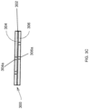
- an embodiment of an oxygen production subsystem 300 is illustrated that may be the oxygen production subsystems 116 and/or 208, discussed above.
- the oxygen production subsystem 300 is provided by an electrochemical oxygen generator/ion exchange oxygen concentrator, although other oxygen production subsystems will fall within the scope of the present disclosure as well.
- the oxygen production subsystem 300 in the illustrated embodiment includes a Proton Exchange Membrane (PEM) 302 that is located between a cathode plate 304 and an anode plate 306.
- PEM Proton Exchange Membrane
- the PEM 302 may include a NAFION ® oxygen transfer membrane as a proton conductor for the PEM 302, which may utilize a sulfonated tetrafluroethylene copolymer, and which is available from DUPONT ® of Wilmington, Delaware, United States.
- the PEM 302 includes a gasket 302a that seals the PEM 302 between the cathode plate 304 and the anode plate 306.
- the PEM 302 is compressed fully (e.g., utilizing approximately 3 to 6 Newton-meters (N-m) of force) between the cathode plate 304 and the anode plate 306, with the gasket 302a sealed utilizing a flange bolting subsystem 308.
- the cathode plate 304 defines an air inlet 304a that may be covered by a polarized membrane 304b that is configured to allow water vapor to pass in only one direction, and to maintain the encapsulation of other gases (e.g., hydrogen).
- the polarized membrane 304b may be provided by a GORE-TEX ® fabric available from W. L. GORE & ASSOCIATES ® of Newark, Delaware, United States, although other membranes will fall within the scope of the present disclosure as well.
- Each of the cathode plate 304 and the anode plate 306 may include a carbon backed metalized substrate with a titanium mesh substrate plated on the carbon membrane, which provides a complete coverage area for electrical conductance to the PEM 302. Electrical contact to the power subsystems 112/206 and the transfer of power from the power subsystems 112/206 to the cathode and anode plates 304 and 306 may be provided by, for example, attaching a copper strip to the titanium mesh substrate on the cathode plate 304 and anode plate 306 (e.g., using epoxy), with the compressive force applied by the flange bolting subsystem 308 operating to provide the necessary adhesion to the surfaces of the cathode plate 304 and anode plate 306.
- a valve 310 is coupled to an oxygen outlet 306a defined by the anode plate 306 and may include fittings, connectors, and/or other couplings that are configured to couple to the oxygen flow coupling that extends to the oxygen outlets 120/212.
- the valve 310 may be provided by a 304L stainless steel needle discharge valve utilizing viton seats, and machined for connection to the anode plate 306 using a viton O-ring (not illustrated.) While a specific oxygen production subsystem 300 has been described, one of skill in the art in possession of the present disclosure will recognize that other oxygen production subsystems may be provided in the wound oxygen supply systems described herein while remaining within the scope of the present disclosure.
- control device 400 is illustrated.
- the control device 400 is provided by a mobile phone.
- other computing devices such as, for example, tablet computing devices, laptop/notebook computing devices, desktop computing devices, smart watches, fitness trackers or other wrist mounted devices, and/or a variety of other computing devices may be provided as the control device 400 while remaining within the scope of the present disclosure.
- the control device 400 includes a chassis 402 that houses the components of the control device, only some of which are illustrated in Fig. 4A .
- the chassis 402 may house a processing subsystem (not illustrated, but which may include one or more hardware processors known in the art) and a memory subsystem (not illustrated, but which may include one or more memory devices known in the art) that includes instructions that, when executed by the processing subsystem, cause the processing subsystem to provide an oxygen production control engine 404 that is configured to perform the functions of the oxygen production control engines and control devices discussed below.
- the chassis 402 may also house a storage subsystem (not illustrated, but which may include one or more storage devices known in the art) that is coupled to the oxygen production control engine 404 (e.g., via a coupling between the storage subsystem and the processing subsystem), and that stores an oxygen production control database 406 that may include any of the information utilized to provide the functionality discussed below.
- the chassis 402 may also house and/or include a display subsystem 408 that is coupled to the oxygen production control engine 404 (e.g., via a coupling between the display subsystem 408 and the processing subsystem) and that is configured to display any of the information discussed below.
- the chassis 402 may also house an input subsystem 410 that is coupled to the oxygen production control engine 404 (e.g., via a coupling between the input subsystem 410 and the processing subsystem) and that is configured to receive and provide any of the input information to the oxygen production control engine 404 as discussed below.
- the chassis 402 may also house a wound oxygen supply system communication subsystem 412 that may include wired and/or wireless communication components (e.g., BLUETOOTH ® subsystems, Near Field Communication (NFC) subsystems, WiFi communication subsystems, wired connector subsystems, etc.) that provide for the wound oxygen supply device communication functionality discussed below.
- a wound oxygen supply system communication subsystem 412 may include wired and/or wireless communication components (e.g., BLUETOOTH ® subsystems, Near Field Communication (NFC) subsystems, WiFi communication subsystems, wired connector subsystems, etc.) that provide for the wound oxygen supply device communication functionality discussed below.
- wound oxygen supply system communication subsystem 412 may provide for the control described below via a variety of wireless or wired connections (e.g., local wired or wireless connections, wired or wireless Internet connections, etc.) While a specific control device 400 has been illustrated and described, one of skill in the art in possession of the present disclosure will recognize that control devices utilized in the present disclosure may include a variety of other components (e.g., mobile phone components) that provide a variety of conventional functionality in addition to the functionality discussed below while remaining within the scope of the present disclosure.
- control devices utilized in the present disclosure may include a variety of other components (e.g., mobile phone components) that provide a variety of conventional functionality in addition to the functionality discussed below while remaining within the scope of the present disclosure.
- FIG. 5 an embodiment of a method 500 for supplying oxygen to a wound is illustrated.
- the inventors of the present disclosure invented the systems and methods described in U.S., Patent No. 8,287,506 , and child patents thereof such as U.S. Patent Publication No.
- wound treatment systems that provides for low dose tissue oxygenation and continuous oxygen adjustability to wound site(s), and operate by monitoring pressure information that is indicative of a pressure in a restricted airflow enclosure that is located adjacent a wound site (e.g., provided by a wound dressing), and using the pressure information to control power provided to an oxygen production subsystem in order to control an oxygen flow that is created by the oxygen production subsystem and provided to the restricted airflow enclosure.
- Those wound treatment systems may include a flow sensor that measures the oxygen flow generated by an oxygen output of the oxygen production subsystem, and a pressure sensor downstream of the flow sensor, the outputs of which may be utilized to control the oxygen flow created by the oxygen production subsystem as discussed above.
- the flow sensor utilized with such wound treatment systems is relatively large, relatively expensive, and requires “plumbing" that takes up space in the wound treatment system chassis and results in a relatively large chassis.
- oxygen production subsystems utilized with such wound treatment systems may provide reduced oxygen production as humidity decreases, which can result in deficient wound site oxygen supply, and can cause the wound treatment systems to increase the power provided to the oxygen production subsystem to a level that can damage the oxygen production subsystem.
- the systems and methods of the present disclosure address these issues by providing a humidity sensor subsystem in the wound oxygen supply system, and utilizing the humidity sensor subsystem to monitor the humidity experienced by the oxygen production subsystem, and report humidity information to an oxygen production control engine that is indicative of that humidity.
- the oxygen production control engine uses the humidity information to control the power provided by a power subsystem to the oxygen production subsystem in order to control an oxygen flow that is created by the oxygen production subsystem and provided through an oxygen outlet to a restricted airflow enclosure adjacent a wound.
- Oxygen production control data is generated that associates, for each of a plurality of different power amounts, a varying oxygen output of the oxygen production system over a range of changing humidity levels, and that oxygen production control data is stored in an oxygen production control database.
- the oxygen production control engine has access to data that indicates, for any particular humidity level, a power that may be applied to the oxygen production subsystem to produce a desired oxygen output and associated oxygen flow rate.
- the oxygen production control engine uses the humidity information received from the humidity sensor subsystem to cause the power subsystem to provide an amount of power to the oxygen production subsystem that causes the creation of oxygen and a subsequent desired oxygen output/flow to the restricted airflow enclosure adjacent the wound.
- the systems and methods of the present disclosure allow for the conventional flow sensor subsystems utilized in the wound treatment systems discussed above to be replaced with the humidity sensor subsystem described herein, providing a reduction in the cost and space required for the sensor subsystem that is utilized to control the production of oxygen by the oxygen production subsystem.
- conventional flow sensor subsystems cost approximately $60 USD, measure approximately 36mm by 20mm, consumes a relatively high amount of energy (up to 40 milliamps (ma)), and requires "plumbing" that includes tubing that connects the flow sensor to the oxygen flow(s) that it measures and that dictates particular positioning of the flow sensor in the chassis to allow the routing of such tubing.
- the humidity sensor subsystem of the present disclosure costs approximately $1.50.
- USD measure approximately 3mm by 3mm
- a relatively simple coupling system that may be mounted anywhere on a circuit board (e.g., that includes the processing system that provides the oxygen production control engine.)
- a circuit board e.g., that includes the processing system that provides the oxygen production control engine.
- the control of oxygen production based on the humidity experienced by the oxygen production subsystem prevents deficient wound site oxygen supply that conventional wound treatment systems experience in low humidity environments, and prevents problems associated with increases in power that are provided to the oxygen production subsystem to address the reduced oxygen production capabilities that result from such low humidity environments.
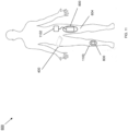
- a patient 600 may be provided including at least one wound.
- the at least one wound is a single wound 602 that is located on a surface of a leg 604 of the patient 600, and that may extend at least partially into the leg 604 of the patient 600.
- a patient may include more than one wound, and the wounds may be located on any portion of the body of the patient 600.
- wounds may be located within the patient 602 (e.g., beneath unwounded, repaired (e.g., surgically repaired), or otherwise healthy skin of the patient), such as on an organ of the patient 600, and thus the wound oxygen supply systems of the present disclosure may be provided internally to the patient 600 while remaining within the scope of the present disclosure.
- Wounds subject to treatment using the wound oxygen supply systems and methods of the present disclosure may include ulcers (diabetic, venous, arterial, pressure, etc.), surgical incisions or closures, amputations, burns, frostbite, insect or animal bites, organ or tissue transplants, organ or tissue implants, tissue grafting, and/or any other wound that would be apparent to one of skill in the art in possession of the present disclosure.
- a bandage subsystem 700 may be positioned adjacent the wound 602 on the leg 604 of the patient 600.
- the bandage subsystem 700 includes tubing 702 that, as discussed above, may be connected on a first end (not illustrated) to the oxygen outlet 120 on the wound oxygen supply system 100, and that includes a second end 704 that is located opposite the tubing 702 from the first end.
- An oxygen permeable membrane 706 extends from the second end 704 of the tubing 702, and may be integrated with the tubing 702, coupled to the tubing 702, and/or provided in a variety of manners that would be apparent to one of skill in the art in possession of the present disclosure.
- the oxygen permeable membrane 706 may be provided by oxygen distribution tape that is positioned over the second end 704 of the tubing and the wound 602 (e.g., such that it engages the intact skin adjacent the wound 602.)
- the oxygen permeable membrane 706 may be provided using a variety of materials that would be apparent to one of skill in the art in possession of the present disclosure.
- the oxygen permeable membrane 706 may be positioned on, around, or otherwise adjacent the wound 602 on the leg 604 of the patient 600, and may be covered with a moisture absorbent dressing 708 (covering the oxygen permeable membrane 706 and any of the exposed wound 602, if present) that is further covered by a reduced vapor pressure, permeable, occlusive dressing 710 (e.g., that covers the moisture absorbent dressing 708, the oxygen permeable membrane 706, the wound 602, and a portion of the tubing 702), creating a restricted airflow enclosure adjacent the wound 602 (e.g., between the wound and the dressing 710.)
- the dressing 710 may be made of a transparent material, and is configured to trap oxygen introduced into the restricted airflow enclosure adjacent the wound 602 to create and maintain an oxygen rich environment.
- the local partial pressure of oxygen at the wound 602 may be increased from a low range of 10 to 60 mm Hg to an oxygen rich environment range of 200 to 760 mm HG using the bandage subsystem and wound oxygen supply system of the present disclosure.
- the bandage subsystem 700 may incorporate a pressure release valve that is configured to ensure that the pressure in the restricted airflow enclosure provided by the dressing 710 does not exceed a maximum desired level.
- the bandage subsystem 700 may provide sensors that may be located in the tubing 702 and/or in the oxygen permeable membrane 706 (i.e., such that they may be positioned in the restricted airflow enclosure provided by the bandage subsystem 700.)
- Fig. 7B illustrates how sensor couplings 712 and 714 may extend through the tubing 702 and may include sensors 712a and 712b located on their distal ends and positioned in the tubing 702 and/or the oxygen permeable membrane 706.
- the sensor couplings 712/714 and sensors 712a/714a may be part of or provided by the humidity sensor subsystems 122a/214a, the pressure sensor subsystems 122b/214b, and/or the other sensor subsystems 122c/214c (e.g., the flow sensor subsystems, the temperature sensor subsystems, and/or any of the other sensor subsystems described herein, as well as sensors that may provide for other monitoring of the wound 602.)
- the sensor couplings 712/714 may be provided by sensor wires that extend through the tubing 702 between the sensors 712a/714a and sensor transducers in the chassis 102 that provide input to the oxygen production control engine.
- sensor subsystems located outside of the chassis 102 of the wound oxygen supply system 100
- sensor subsystems may be located within and outside of the chassis 102 of the wound oxygen supply system 100 in a variety of manners that will fall within the scope of the present disclosure as well.
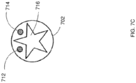
- the tubing 702 may include a plurality of lumens, including an inner lumen 716 that, in the illustrated embodiment, is provided with a star-like configuration that operates to resist kinking of the tubing 702 while still providing for oxygen flow if the tubing 702 is bent.
- a variety of other kink-resistant components and/or materials may be provided with the tubing 702 to provide similar functionality while remaining within the scope of the present disclosure.
- Fig. 7D illustrates how the tubing 702 may define a plurality of apertures 718 adjacent the second end 704 of the tubing 702 to aid in the delivery of oxygen to the wound 602.
- an oxygen flow 720 produced by the oxygen production subsystem and directed through the tubing 702 to the wound 602 may exit the tubing 702 and enter the restricted airflow enclosure adjacent the wound 702 through the multiple different apertures 718, as well as through a distal end of inner lumen 716, improving the flow of oxygen to the wound 602.
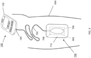
- a bandage subsystem/wound oxygen supply system 800 which includes the wound oxygen supply system 200 of Figs. 2A-2C coupled to or integrated into a bandage system, may be positioned adjacent the wound 602 on the leg 604 of the patient 600.
- the bandage subsystem 800 includes a moisture absorbent dressing 802 covering the wound 602, and a reduced vapor pressure, permeable, occlusive dressing 804 (e.g., that covers the moisture absorbent dressing 802 and the wound 602), creating a restricted airflow enclosure adjacent the wound 602 (e.g., between the wound and the dressing 804.)
- the dressing 804 may be made of a transparent material, and is configured to trap oxygen introduced into the restricted airflow enclosure adjacent the wound 602 to create and maintain an oxygen rich environment.
- the wound oxygen supply system 200 is coupled to or integrated into the dressing 804, which includes an oxygen channel 806 that is configured to channel oxygen generated by the wound oxygen supply system 200 and provided via the oxygen outlet 212 into the restricted airflow enclosure created by the dressing 804 and located adjacent the wound 602.
- an oxygen channel 806 that is configured to channel oxygen generated by the wound oxygen supply system 200 and provided via the oxygen outlet 212 into the restricted airflow enclosure created by the dressing 804 and located adjacent the wound 602.
- Experimental embodiments have found that the local partial pressure of oxygen at the wound 602 may be increased from a low range of 10 to 60 mm Hg to an oxygen rich environment range of 200 to 760 mm HG using the bandage subsystem/wound oxygen supply system of the present disclosure.
- the bandage subsystem/wound oxygen supply system 800 may include an oxygen permeable membrane that is similar to the oxygen permeable membrane 706 discussed above.
- an oxygen permeable membrane may be coupled to the oxygen outlet 212 on the wound oxygen supply system 200 (e.g., via the oxygen channel 806) and located immediate adjacent the wound 602 (e.g., via the oxygen channel 806 that may, for example, extend through the moisture absorbent dressing 802.)
- an oxygen permeable membrane may be provided in the bandage subsystem/wound oxygen supply system 800 in a variety of manners that will fall within the scope of the present disclosure as well.
- the bandage subsystem/wound oxygen supply system 800 may include sensors that are located outside of the chassis 202 of the wound oxygen supply system 200 (i.e., such that they are positioned in the oxygen channel 806, an oxygen permeable membrane included in the bandage subsystem/wound oxygen supply system 800, and/or the restricted airflow enclosure provided by the bandage subsystem/wound oxygen supply system 800) in substantially the same manner as described above with the wound oxygen supply system 100.
- the wound oxygen supply system 200 may be coupled to tubing that is similar to the tubing 702 discussed above and that provides oxygen created by the wound oxygen supply system 200 to a bandage subsystem that is similar to the bandage subsystem 700 discussed above.
- the wound oxygen supply system 200 may be coupled to or integrated into a bandage subsystem that is similar to the bandage subsystem/wound oxygen supply system 800 discussed above.
- bandage subsystems may be modified to provide a bandage subsystem (with a tubing-coupled wound oxygen supply system, an integrated wound oxygen supply system, etc.) that is configured to be provided on a wound that is internal to the patient 600 (e.g., beneath the skin of the patient such as, for example, located on an internal organ of the patient 600) so that oxygen may be provided to internal wounds using the teachings of the present disclosure.
- a bandage subsystem with a tubing-coupled wound oxygen supply system, an integrated wound oxygen supply system, etc.
- the method 500 then proceeds to block 504 where humidity information is received that is indicative of a humidity experienced by the oxygen production subsystem in the wound oxygen supply system.
- the bandage subsystem 700 is illustrated coupled to the patient 600 and providing a restricted airflow enclosure adjacent the wound 602, with the tubing 702 extending from the bandage subsystem 700 to the oxygen outlet 120 on the wound oxygen supply system 100.
- the humidity sensor subsystem 122a in the wound oxygen supply system 100 may operate to detect a humidity level (e.g., within the chassis 102 of the wound oxygen supply system 100, adjacent to and outside the chassis 102 of the wound oxygen supply system 100, in the tubing 702, in the restricted airflow enclosure provided by the bandage subsystem 700, etc.) and, in response, generate humidity information that is indicative of that humidity level that is being experienced by the oxygen production subsystem 116 (and that effects the oxygen production operations of that oxygen production subsystem 116 as discussed above.) The humidity sensor subsystem 122a and/or the oxygen production control engine 104 may then operate such that, at block 504, the
- the bandage subsystem/wound oxygen supply system 800 is illustrated coupled to the patient 600 and providing a restricted airflow enclosure adjacent the wound 602, with the control device 400 communicatively coupled to the wound oxygen supply system 200.
- the wound oxygen supply system communication subsystem 412 in the control device 400 and the control device communication subsystem 204 in the wound oxygen supply system 200 may enable the wound oxygen supply system 200 and the control device to pair (e.g., via a BLUETOOTH ® or other wireless communication pairing protocol), link, and/or otherwise establish a communication channel such that they may exchange data or other information as discussed below.
- the configuration of the bandage subsystem/wound oxygen supply system 800 and the control device 400 allows the bandage subsystem/wound oxygen supply system 800 to be provided on a wound, and the control device 400 to be comfortably positioned at a variety of locations on and/or adjacent the patient (e.g., on a belt, in a pocket, in a bag, strapped to a limb, etc.) while still enabling control of the wound oxygen supply system 200.
- the humidity sensor subsystem 214b in the wound oxygen supply system 200 may operate to detect a humidity level (e.g., within the chassis 202 of the wound oxygen supply system 200, adjacent to and outside the chassis 202 of the wound oxygen supply system 200, in the oxygen channel 806, in the restricted airflow enclosure provided by the bandage subsystem/wound oxygen supply system 800, etc.) and, in response, generate humidity information that is indicative of that humidity level that is being experienced by the oxygen production subsystem 208 (and that effects the oxygen production operations of that oxygen production subsystem 208 as discussed above.)
- the humidity sensor subsystem 122a and/or the control device communication subsystem 204 may then operate such that the control device communication subsystem 204 receives the humidity information generated by the humidity sensor subsystem 122a.
- the control device communication subsystem 204 may then operate at block 504 to transmit, via the communication connection with the control device 400 established as discussed above, the humidity information to the control device 400 such that the oxygen production control engine 404 receives that humidity information through the wound oxygen supply system communication subsystem 412.
- the method 500 then proceeds to block 506 where the humidity information is used to control the power provided to the oxygen production subsystem.
- the oxygen production control engine 104 uses the humidity information received from the humidity sensor subsystem 122a to control the power provided by the power subsystem 112 to the oxygen production subsystem 116.
- the oxygen production control database 106 may include oxygen production control data that associates, for each of a plurality of different power amounts, a varying oxygen output of the oxygen production subsystem 116 over a range of different humidity levels.
- the oxygen production control engine 104 may determine a desired oxygen flow rate or pressure in the restricted airflow enclosure (e.g., as programmed in the wound oxygen supply system 100), and access the oxygen production control data and determine, using the particular humidity level indicated by the humidity information received at block 504, a particular power amount that will cause the oxygen production subsystem 116 to produce an oxygen output that will provide that desired oxygen flow rate or pressure in the restricted airflow enclosure.
- the oxygen production control engine 104 may then cause the power subsystem 112 to provide that particular power amount to the oxygen production subsystem 116 by, for example, sending an instruction to the power subsystem 112 to transmit that power amount to the oxygen production subsystem 116.
- the oxygen production control engine 404 uses the humidity information received from the humidity sensor subsystem 214a to control the power provided by the power subsystem 206 to the oxygen production subsystem 208.
- the oxygen production control database 406 may include oxygen production control data that associates, for each of a plurality of different power amounts, a varying oxygen output of the oxygen production subsystem 208 over a range of different humidity levels.
- the oxygen production control engine 404 may determine a desired oxygen flow rate or pressure in the restricted airflow enclosure (e.g., as programmed in the wound oxygen supply system 100), and access the oxygen production control data and determine, using the particular humidity level indicated by the humidity information received at block 504, a particular power amount that will cause the oxygen production subsystem 208 to produce an oxygen output that will provide that desired oxygen flow rate or pressure in the restricted airflow enclosure.
- the oxygen production control engine 404 may then transmit an instruction via the wound oxygen supply system communication subsystem 412 to the control device communication subsystem 204 in the wound oxygen supply system 200, and the control device communication subsystem 204 may, in response, cause the power subsystem 206 to provide that particular power amount to the oxygen production subsystem 208 by, for example, forwarding that instruction to the power subsystem 206 to transmit that power amount to the oxygen production subsystem 208.
- the method 500 then proceeds to block 508 where the oxygen production subsystem produces an oxygen flow using the power provided according to the humidity information.
- the oxygen production subsystem 116/208 uses the power provided by the power subsystem 112/206 at block 506 to generate oxygen and product an oxygen flow.
- the oxygen production subsystem 116/208 upon receiving the power amount from the power subsystem 112/206, the oxygen production subsystem 116/208 will operate to draw air in through the oxygen inlet 118/210 that includes approximately 21% oxygen, and that air is then directed through the oxygen production subsystem 116/208, which operates to perform an electrochemical process that concentrates the oxygen included in that air to create an oxygen mixture that approximately 99% pure oxygen, and provides that oxygen mixture as an oxygen flow that is directed to the oxygen outlet 120/212.
- the power amount (e.g., the current) provided by the power subsystem 112/206 may operate to provide for proportional or otherwise related oxygen generation (i.e., oxygen concentration from the air received through the oxygen inlet 118/210), thereby producing the oxygen flow with an oxygen flow rate that is proportion or otherwise related to the amount of power supplied by the power subsystem 112/206 to the oxygen production subsystem 116/208 (e.g., increasing the current increases the electrochemical process performed by the oxygen production subsystem 116/208 and thereby increases the subsequent oxygen flow rate produced by the oxygen production subsystem 116/208, while decreasing the current decreases the electrochemical process performed by the oxygen production subsystem 116/208 and thereby decreases the subsequent oxygen flow rate produced by the oxygen production subsystem 116.)
- the power subsystem 112/206 may include lithium batteries (e.g., 7.4 volt lithium batteries) and a regulator that is configured to vary the amperage over a range of approximately 15 milliamps to approximately 150 milliamps, which operates to provide oxygen flow rates in the
- the oxygen flow generated by the oxygen production subsystem 116/208 is then directed out of the chassis 102/202 via the oxygen outlet 120/212.
- the oxygen flow generated by the oxygen production subsystem 116 may exit the oxygen outlet 120 and enter the tubing 702, and be directed by the tubing 702 to the oxygen permeable membrane 706 such that the oxygen flow is introduced into the restricted airflow enclosure provided by the bandage subsystem 700.
- the oxygen flow generated by the oxygen production subsystem 208 may exit the oxygen outlet 202 and be directed by the oxygen channel 806 such that the oxygen flow is introduced into the restricted airflow enclosure provided by the bandage subsystem 700.
- the increased available oxygen provided in the oxygen flow introduced to the restricted airflow enclosure may be metabolized at the cellular level, and will operate to stimulate an increase in growth factors, epithelialization, granulation tissue, glycosaminoglycan production, and collagen synthesis.
- the method 500 then proceeds to optional block 510 where other sensor information may be received.
- other sensor information may be generated by the wound oxygen supply system and utilized in a variety of manners, a few of which are discussed below.
- the humidity sensor subsystem and use of humidity information to control the oxygen flow created by the oxygen production subsystem have been found to be sufficient in providing for enhanced wound healing as discussed above.
- any other sensor subsystem(s) provided in the wound oxygen supply system 100 may operate to sense, measure, and/or otherwise detect a variety of factors (e.g., within the chassis 102 of the wound oxygen supply system 100, adjacent to and outside the chassis 102 of the wound oxygen supply system 100, in the tubing 702, in the restricted airflow enclosure provided by the bandage subsystem 700, etc.) and, in response, generate information that is indicative of that factor.
- Those other sensor subsystem(s) and/or the oxygen production control engine 104 may then operate such that, at block 504, the oxygen production control engine 104 receives the other sensor information generated by those other sensor subsystem(s).
- any other sensor subsystem(s) provided in the wound oxygen supply system 200 may operate to sense, measure, and/or otherwise detect a variety of factors (e.g., within the chassis 202 of the wound oxygen supply system 200, adjacent to and outside the chassis 202 of the wound oxygen supply system 200, in the oxygen channel 806, in the restricted airflow enclosure provided by the bandage subsystem/wound oxygen supply system 800, etc.) and, in response, generate information that is indicative of that factor.
- Those other sensor subsystem(s) and/or the control device communication subsystem 204 may then operate such that the control device communication subsystem 204 receives the other sensor information generated by those other sensor subsystem(s).
- the control device communication subsystem 204 may then operate at block 504 to transmit, via the communication connection with the control device 400 established as discussed above, the other sensor information to the control device 400 such that the oxygen production control engine 404 receives that other sensor information through the wound oxygen supply system communication subsystem 412.
- the other sensor subsystems in the wound oxygen supply systems 100 and 200 may include the pressure sensor subsystem 122b and 214b, respective which may operate to provide pressure information to the oxygen production control engine 104 and 404, respectively, that is indicative of a pressure in the restricted airflow enclosure provided by the bandage subsystem 700 and bandage subsystem/wound oxygen supply system 800, respectively.
- the other sensor subsystems in the wound oxygen supply systems 100 and 200 may include the flow rate sensor subsystem which may operate to provide flow rate information to the oxygen production control engine 104 and 404, respectively, that is indicative of a flow rate of oxygen to the restricted airflow enclosure provided by the bandage subsystem 700 and bandage subsystem/wound oxygen supply system 800, respectively.
- the other sensor subsystems in the wound oxygen supply systems 100 and 200 may include the temperature sensor subsystems which may operate to provide temperature information to the oxygen production control engine 104 and 404, respectively, that is indicative of a temperature in the restricted airflow enclosure provided by the bandage subsystem 700 and bandage subsystem/wound oxygen supply system 800, respectively.
- the other sensor subsystems in the wound oxygen supply systems 100 and 200 may include the pH sensor subsystems which may operate to provide pH information to the oxygen production control engine 104 and 404, respectively, that is indicative of a pH in the restricted airflow enclosure provided by the bandage subsystem 700 and bandage subsystem/wound oxygen supply system 800, respectively.
- the other sensor subsystems in the wound oxygen supply systems 100 and 200 may include the perfusion sensor subsystems which may operate to provide perfusion information to the oxygen production control engine 104 and 404, respectively, that is indicative of perfusion in the restricted airflow enclosure provided by the bandage subsystem 700 and bandage subsystem/wound oxygen supply system 800, respectively.
- the method 500 then proceeds to optional block 512 where the other sensor information may be used to control the power provided to the oxygen production subsystem.
- the oxygen production control engine 104 may use the other sensor information received from the other sensor subsystem(s) to control the power provided by the power subsystem 112 to the oxygen production subsystem 116.
- the wound oxygen supply systems 100 and/or 200 may provide the humidity sensor subsystem and its functionality described above to cause the oxygen production subsystem to generate a desired oxygen flow to the restricted airflow enclosure, while using the pressure sensor subsystem to determine when the pressure in restricted airflow enclosure reaches a maximum level and, in response, prevent the oxygen production subsystem from generating oxygen until that pressure falls below the maximum level.
- the use of the humidity sensor subsystem and pressure sensor subsystem in place of conventional flow sensor subsystem/pressure sensor subsystem devices provides for a reduced chassis size and ability to address humidity related issues with the oxygen production subsystem, while still enabling precise control of the oxygen supply to the restricted airflow enclosure adjacent the wound.
- the oxygen production control engine 104 may also utilize any of the pressure information, flow rate information, temperature information, pH information, and/or perfusion information along with the humidity information to determine a power amount to provide to the oxygen production subsystem 116, and then cause the power subsystem 112 to provide a particular power amount to the oxygen production subsystem 116 by, for example, sending an instruction to the power subsystem 112 to transmit that power amount to the oxygen production subsystem 116.
- the other sensor information received at block 510 may not be used to control power provided to the oxygen production subsystem 116, but rather may instead be used to monitor the wound 602 or perform other functionality.
- sensor information such as pressure information may be utilized to ensure the pressure in the restricted airflow enclosure is at a desired level, to verify that the patient 600 is using the wound oxygen supply system, or to perform other functions that would be apparent to one of skill in the art in possession of the present disclosure.
- the oxygen production control engine 404 uses the other sensor information received from the other sensor subsystem(s) to control the power provided by the power subsystem 206 to the oxygen production subsystem 208.
- the oxygen production control engine 104 may utilize any of the pressure information, flow rate information, temperature information, pH information, and/or perfusion information along with the humidity information to determine a power amount to provide to the oxygen production subsystem 208, and then transmit an instruction via the wound oxygen supply system communication subsystem 412 to the control device communication subsystem 204 in the wound oxygen supply system 200, and the control device communication subsystem 204 may, in response, cause the power subsystem 206 to provide that particular power amount to the oxygen production subsystem 208 by, for example, forwarding that instruction to the power subsystem 206 to transmit that power amount to the oxygen production subsystem 208.
- the other sensor information received at block 510 may not be used to control power provided to the oxygen production subsystem 208, but rather may instead be used to monitor the wound 602.
- the method 500 then proceeds to optional block 514 where the oxygen production subsystem may produce the oxygen flow using the power provided according to the other sensor information in substantially the same manner as described above with reference to block 508.
- the method 500 may then return to block 504 where the humidity information is received that is indicative of the humidity experienced by the oxygen production subsystem in the wound oxygen supply system, and the method 500 loops back through blocks 504-508, and in some cases optional blocks 510-514, to provide the oxygen flow to the restricted airflow enclosure.
- oxygen may be provided to a wound and, in some cases, continuously varied to enhance the healing of that wound.
- combinations of the teachings above may be provided to enhance the healing of more than one wound.
- Fig. 11 illustrates the patient 600 of Fig. 6 with the wound 602 on the leg 604, and including a second, smaller wound on a leg 1100 as well.
- an embodiment of the bandage subsystem/wound oxygen supply system 800 is provided on the relatively larger wound 602, with a connection (via a power connector provided by the power subsystem 206) to an external portable power source 1102 (e.g., a battery, solar energy collecting clothing, etc.) that is provided to produce an increased level of oxygen generation by the wound oxygen supply system 200 for the larger wound 602, and that may be worn by the patient 600 (e.g., on a belt, in a pocket, etc.)
- an embodiment of the bandage subsystem/wound oxygen supply system 800 is provided on the relatively smaller wound on the leg 1100, and which includes sufficient internal power (e.g., via an internal battery) to provide sufficient oxygen generation by the wound oxygen supply system 200 for the smaller wound on the leg 1100.
- the control device 400 may provide for control of the multiple wound oxygen supply systems utilized by the patient 600 in substantially the same manner as described above.
- Fig. 12 illustrates how a single wound oxygen supply system 100 may be utilized to treat multiple wounds on a patient, as discussed above.
- a first bandage subsystem 700 has been placed on a wound on the shoulder of the patient 600
- a second bandage subsystem 700 has been placed on a wound on the leg 604 of the patient 600
- each of those first and second bandage subsystems 700 have been coupled to oxygen outlet(s) on the chassis 102 of the wound oxygen supply system 100.
- the chassis 102 may house multiple oxygen production subsystems, each with a dedicated oxygen outlet, sensor subsystems, and/or other features discussed above, and with each configured to supply oxygen to a wound in substantially the same manner as discussed above.
- a single oxygen production subsystem may be coupled to a single oxygen outlet, with a single set of sensor subsystems, and may be coupled to multiple wounds (e.g., via multiple tubings branched tubing, etc.) to supply oxygen to those multiple wounds in substantially the same manner as discussed above.
- multiple wounds e.g., via multiple tubings branched tubing, etc.
- the wound oxygen supply systems 100 and 200 may operate to receive a variety of input information via their input subsystems (e.g., the input subsystem 110 on the wound oxygen supply system 100, the input subsystem 410 on the control device 400 that may utilize the wound oxygen supply system communication subsystem 412 to transmit input information to the wound oxygen supply system 200, etc.) and/or display a variety of display information via their display subsystems (e.g., the display subsystem 108 on the wound oxygen supply system 100, the display subsystem 408 on the control device 400 that may utilize the wound oxygen supply system communication subsystem 412 to receive display information from the wound oxygen supply system 200, etc.)
- input information may include control instructions to adjust a desired oxygen flow rate produced by the oxygen production subsystems 116/208, cause software for the wound oxygen supply systems 100 and/or 200 to be updated, and/or any of a variety of other input information that would be apparent to one of skill in the art in possession of the present disclosure.
- display information may include the display of a current oxygen flow rate produced by the oxygen production subsystems 116/208, the status of a software update for the wound oxygen supply systems 100 and/or 200, and/or any of a variety of other display information that would be apparent to one of skill in the art in possession of the present disclosure.
- the communication subsystems provided in the wound oxygen supply systems 100 and/or 200 may be utilized to communicate with other entities as well.
- the wound oxygen supply system 100 may utilize its communication subsystem to download data (e.g., operating instructions) for use in at least one subsequent operation of the wound oxygen supply system 100, and/or upload data (e.g., previously generated data) that describes previous operation of the wound oxygen supply system 100.
- data e.g., operating instructions
- upload data e.g., previously generated data
- control device 400 may utilize its communication subsystem to download data (e.g., operating instructions) for use in at least one subsequent operation of the wound oxygen supply system 200, and in some cases provide that data to the wound oxygen supply system 200, and/or upload data (e.g., previously generated data) that describes previous operation of the wound oxygen supply system 100.
- data e.g., operating instructions
- upload data e.g., previously generated data
- data generated by the wound oxygen supply system and describing the use of that wound oxygen supply system may be saved and reported back to a caregiver or other entity, and a caregiver or other entity may remotely control the operation of the wound oxygen supply systems to remotely care for the patient.
- the systems and methods of the present disclosure allow for the conventional flow sensor subsystems utilized in the wound treatment systems discussed above to be replaced with the humidity sensor subsystem described herein, providing a reduction in the cost and size of the wound oxygen supply system, while still enabling low dose tissue oxygenation and continuous oxygen adjustability to a wound site, preventing deficient wound site oxygen supply that conventional wound treatment systems experience in low humidity environments, and preventing problems associated with increases in power that are provided to the oxygen production subsystem to address the reduced oxygen production capabilities that result from such low humidity environments
Description
- The present disclosure relates generally to wound healing, and more particularly to systems and methods for supplying oxygen to a wound to accelerate the healing of damaged tissue and/or promote tissue viability.
- When tissue is damaged and a wound results, a four phase healing process begins, and optimal metabolic function of cells in the tissue to repopulate the wound requires that oxygen be available for all of these phases of wound healing. Furthermore, the more layers of tissue that are damaged, the greater the risk is for complications to occur in the wound healing process, and difficult-to-heal wounds can encounter barriers to the wound healing process and experience delays in one or more of the last three phases of wound healing. For example, one of the most common contributing factors to delays in the healing of wounds such as venous leg ulcers, diabetic foot ulcers, and pressure ulcers, is the problem of chronic wound ischemia. Chronic wound ischemia a pathological condition that restricts blood supply, oxygen delivery, and blood request for adequate oxygenation of tissue, which inhibits normal wound healing.
- One conventional standard of care for treating difficult-to-heal wounds involves the use of an advanced wound dressing, or a combination of advanced wound dressings, that provide a dressing treatment system. The advanced wound dressing may be positioned on the wound site and, in some cases, the surrounding intact skin, to provide a wound site enclosure. The advanced wound dressing typically includes materials having properties for promoting moist wound healing, managing wound exudate, and helping control wound bioburden. Those material provided in combination operate to produce limited moisture vapor permeability, and the more occlusive the dressing, the lower the amount of ambient air (and thus a respective lower amount of oxygen) that is available to the wound site.
- 100% oxygen exerts a partial pressure of 760 millimeters (mm) of mercury (Hg), and ambient air includes about 21% oxygen, so ambient air exerts a partial pressure of oxygen of about 159 mm Hg. A typical advanced wound dressing or wound dressing system utilizing materials that provide limited moisture vapor permeable operates to impacts the available oxygen for the wound site, thereby limiting the partial pressure of oxygen at the enclosed wounds site to about 10-60 mm Hg. Fresh air (and its associated higher oxygen amount) is then only provided to the wound site when the dressing is changed, and dressings may remain covering the wound site for up to seven days before a dressing change is required. As such, the limited moisture vapor permeability of advanced wound dressings produce a reduced oxygen wound environment that works against the optimal metabolic function of cells to repopulate the wound during all the phases of wound healing.
- Specific examples of conventional systems and methods to provide tissue oxygenation for difficult-to-heal wounds include the intermitted or continuous application of topical hyperbaric oxygen to the wound site. Intermittent topical hyperbaric oxygen treatment systems involve providing a sealed extremity or partial body chamber, along with a connected source of pure oxygen at a relatively high flow rate, and positioning the wounded limb or body area in the sealed extremity chamber or partial body chamber. The oxygen source will then supply the chamber with up to 100% oxygen at flow rates that may exceed 300 liters per hour, pressurizing the interior of the chamber at up to 1.05% normal atmospheric pressure, thereby topically increasing the available oxygen for cellular processing at the affected wound site. For example, during oxygen application, the partial pressure of oxygen exerted inside the sealed extremity or partial body chamber may attain 798 mm Hg, and may be applied for about 90 minutes. These and similar methods of applying intermittent topical hyperbaric oxygen are restrictive, cumbersome, can only supply oxygen to the affected area intermittently with no systemic application, and only provide for a minimal increase in atmospheric pressure (about 5%). Therefore, the effects of the oxygen therapy on wounds using these methods tend to be minimal, which is evidenced by the lack of commercial success of topical hyperbaric oxygen extremity chambers.
- Other conventional systems and methods to provide tissue oxygenation include disposable devices that provide for the transmission of gases in ionic form through ion-specific membranes in order to apply supplemental oxygen directly to a wound site. These devices are typically battery powered, disposable, oxygen supplemented bandages that are provided directly over the wound site, and utilize electrochemical oxygen generation using variations of a 4 electron formula originally developed for NASA. In such systems, the amount of oxygen that can be applied to the wound is typically in the range of 3 to 15 milliliters per hour, and desired oxygen flow rates are generated by utilizing corresponding, preselected battery sizes with predefined amperages. As such, these devices are either "on or off", and do not have the ability to deliver a varying or adjustable oxygen flow or oxygen flow rate without obtaining a new device and/or a different battery having an amperage that will produce the desired flow rate. The utilization of fixed, non-variable oxygen flows and oxygen flow rates introduces corresponding limitations in the treatment of different sizes and types of wounds, and tends to result in the wound treatment system being oversized or undersized for the wound to which it is being applied.
- The inventors of the present disclosure co-invented systems and methods that address the issues with the conventional wound treatment systems discussed above. For example,
U.S., Patent No. 8,287,506 andU.S. Patent Publication No. 2016/0082238 describe wound treatment systems that provide for low dose tissue oxygenation and continuous oxygen adjustability to wound site(s) to create a controlled hyperoxia and hypoxia wound environment for damaged tissue, accelerates wound healing, and promotes tissue viability. Those systems and methods operate by monitoring pressure information that is indicative of a pressure in a restricted airflow enclosure that is located adjacent a wound site (e.g., provided by a wound dressing), and using the pressure information to control power provided to an oxygen production subsystem in order to control an oxygen flow that is created by the oxygen production subsystem and provided to the restricted airflow enclosure. In some embodiments, those wound treatment systems include a flow sensor that measures the oxygen output of the oxygen production subsystem, with a pressure sensor downstream of the flow sensor that measures the pressure that may be utilized to control the oxygen flow created by the oxygen production subsystem as discussed above. - However, the inventors of the present disclosure have discovered that such wound treatment systems suffer from a number of issues. For example, the flow sensor utilized with such wound treatment systems is relatively large (currently approximately 36mm by 20mm), relatively expensive (currently approximately $60 USD), consumes a relatively high amount of energy (up to 40 milliamps (ma)), and requires "plumbing" (i.e., tubing that connects the flow sensor to the oxygen flow(s) that it measures) that takes up space in the wound treatment system chassis and results in a larger chassis than would otherwise be required absent the flow sensor. Furthermore, it has been discovered that oxygen production subsystem utilized with such wound treatment systems may provide greatly reduced oxygen production as humidity decreases, which can result in deficient wound site oxygen supply, and can cause the wound treatment systems to increase the power provided to the oxygen production subsystem to a level that can damage the oxygen production subsystem.
- Accordingly, it would be desirable to provide an improved wound treatment system.
- Document
US 2016/0082238 A1 discloses a wound treatment system that includes a housing. A processor is located in the housing. A pressure monitoring system is coupled to the processor. A power delivery system is located in the housing and coupled to the processor. An oxygen concentrator is located in the housing and coupled to the power delivery system. The oxygen concentrator includes a plurality of oxygen outlets. The processor is configured to receive pressure information from the pressure monitoring system that is indicative of a pressure in a restricted airflow enclosure provided by a dressing and located adjacent a wound site; and use the pressure information to control the power provided from the power delivery system to the oxygen concentrator in order to control an oxygen flow created by the oxygen concentrator and provided through one of the plurality of oxygen outlets to the restricted airflow enclosure. -
Document CN 106 345 026 A discloses an intelligent oxygen saving and transferring apparatus. The apparatus comprises a respiratory flow sensor for monitoring the inhaling and exhaling information of the nostril; a blood oxygen saturation detector for monitoring the blood saturation information; an oxygen catheter; a gas flow meter provided on the oxygen catheter for monitoring the oxygen outflow from the oxygen catheter; a controller for receiving the monitoring information from the respiratory flow sensor and the blood oxygen saturation detector and regulating the oxygen output from the oxygen catheter through an electrically controlled valve based on the monitoring information. The apparatus regulates the open degree of the electrically controlled valve based on the monitoring information from the respiratory flow sensor and the blood oxygen saturation detector. - According to the invention, a wound oxygen supply system according to claim 1 and a method for supplying oxygen to a wound according to claim 5 are provided.
-
-
Fig. 1A is a schematic view illustrating an embodiment of a wound oxygen supply system. -
Fig. 1 Bis a perspective view illustrating an embodiment of the wound oxygen supply system ofFig. 1A . -
Fig. 2A is a schematic view illustrating an embodiment of a wound oxygen supply system. -
Fig. 2B is a top perspective view illustrating an embodiment of the wound oxygen supply system ofFig. 2A . -
Fig. 2C is a bottom perspective view illustrating an embodiment of the wound oxygen supply system ofFig. 2A -
Fig. 3A is an exploded perspective view illustrating an embodiment of an oxygen production subsystem used in the wound oxygen supply systems ofFigs. 1A-1B and2A-2C . -
Fig. 3B is a front view illustrating an embodiment of the oxygen production subsystem ofFig. 3A . -
Fig. 3C is a cross sectional view illustrating an embodiment of the oxygen production subsystem ofFig. 3B . -
Fig. 4A is a schematic view illustrating an embodiment of a control device that may be used to control the wound oxygen supply system ofFigs. 2A-2C . -
Fig. 4B is a perspective view illustrating an embodiment of the control device ofFig. 4A . -
Fig. 5 is a flow chart illustrating an embodiment of a method for supplying oxygen to a wound. -
Fig. 6 is a schematic view illustrating an embodiment of a patient with a wound. -
Fig. 7A is a cross sectional view illustrating an embodiment of a bandage subsystem positioned on the wound of the patient ofFig. 5 . -
Fig. 7B is a perspective view illustrating an embodiment of tubing and an oxygen permeable membrane that is may be included in the bandage subsystem ofFig. 7A . -
Fig. 7C is a cross sectional view illustrating an embodiment of the tubing ofFig. 7B . -
Fig. 7D is a perspective view illustrating an embodiment of the tubing ofFig. 7C . -
Fig. 8 is a cross sectional view illustrating an embodiment of the wound oxygen supply system ofFigs. 2A-2C included as part of a bandage subsystem that is positioned on the wound of the patient ofFig. 6 . -
Fig. 9 is a front/perspective view illustrating an embodiment of the wound oxygen supply system ofFigs. 1A-1B coupled to the bandage subsystem ofFig. 7A that is positioned on the wound of the patient ofFig. 6 . -
Fig. 10 is a front/perspective view illustrating an embodiment of the control device ofFigs. 4A-4B controlling the wound oxygen supply system and bandage subsystem of Fig. 9A. -
Fig. 11 is a schematic view illustrating an embodiment of the patient ofFig. 6 with additional wounds, and utilizing additional wound oxygen supply systems and bandage subsystems of Fig. 9A and the control device ofFigs. 4A-4B . -
Fig. 12 is a schematic view illustrating an embodiment of the patient ofFig. 6 with additional wounds, and utilizing the wound oxygen supply system ofFig. 1 and multiple bandage subsystems ofFig. 7A-7D . - Some embodiments of wound oxygen supply systems and methods will now be described with reference to the figures, but one of skill in the art in possession of the present disclosure will recognize that a wide variety of modification to those embodiments will fall within the scope of the present disclosure as well. As such, different combinations of the different components and configurations of the wound oxygen supply systems discussed below, substitutions of different components in different wound oxygen supply systems, and/or any other modifications that would be apparent to one of skill in the art in possession of the present disclosure are envisioned as falling within the scope of the present disclosure.
- Certain references are made to non-SI-units. These can be converted to Sl-units using the following factor:
1 mm HG = 133.3 Pa. - Referring now to
Figs. 1A and1B , an embodiment of a woundoxygen supply system 100 is illustrated. The woundoxygen supply system 100 illustrated inFigs. 1A and1B provides an example of an wound treatment device that includes the oxygen production subsystems, sensor subsystems, power subsystems, and control subsystems in a single chassis that may be coupled to oxygen delivery tubing that is further coupled to a bandage subsystem. In the illustrated embodiment, the woundoxygen supply system 100 includes achassis 102 that houses the components of the woundoxygen supply system 100, only some of which are illustrated inFig. 1A . For example, thechassis 102 may house a processing subsystem (not illustrated, but which may include one or more hardware processors known in the art) and a memory subsystem (not illustrated, but which may include one or more memory devices known in the art) that includes instructions that, when executed by the processing subsystem, cause the processing subsystem to provide an oxygenproduction control engine 104 that is configured to perform the functions of the oxygen production control engines and wound oxygen supply systems discussed below. Thechassis 102 may also house a storage subsystem (not illustrated, but which may include one or more storage devices known in the art) that is coupled to the oxygen production control engine 104 (e.g., via a coupling between the storage subsystem and the processing subsystem) and that stores an oxygenproduction control database 106 that may include any of the information utilized to provide the functionality discussed below. - The
chassis 102 may also house and/or include adisplay subsystem 108 that is coupled to the oxygen production control engine 104 (e.g., via a coupling between thedisplay subsystem 108 and the processing subsystem) and that is configured to display any of the information discussed below. Thechassis 102 may also house aninput subsystem 110 that is coupled to the oxygen production control engine 104 (e.g., via a coupling between theinput subsystem 110 and the processing subsystem) and that is configured to receive and provide any of the input information (e.g., via theinput buttons Fig. 1B ) to the oxygenproduction control engine 104 as discussed below. While thedisplay subsystem 108 and theinput subsystem 110 are illustrated and described as separate subsystems, one of skill in the art in possession of the present disclosure will recognized that they may be combined (e.g., in a touch-input display subsystem) while remaining within the scope of the present disclosure. According to the invention, thechassis 102 houses apower subsystem 112 that is coupled to the oxygen production control engine 104 (e.g., via a coupling between thepower subsystem 112 and the processing subsystem) and that may include one or more batteries, adapters, converters, and/or a variety of other power components that would be apparent to one of skill in the art in possession of the present disclosure. For example, in some of the specific examples discussed below, thepower subsystem 112 includes a rechargeable battery and is coupled to apower connector 114 that is configured to connect to a power source to provide power to thepower subsystem 112 to charge the rechargeable battery. However, one of skill in the art in possession of the present disclosure will recognize that direct power source systems (e.g., systems that connect to a power source outside thechassis 102 and thus do not require an internal battery or other stored power source to provide power, but that may be utilized in conjunction with internal batteries in some embodiments) may be provided while remaining within the scope of the present disclosure as well. - The
chassis 102 also houses an oxygen production subsystem 116 that is coupled to thepower subsystem 112 and that is configured to produce oxygen in response to power supplied by thepower subsystem 112, as discussed in further detail below. The oxygen production subsystem 116 is coupled to anoxygen inlet 118 that is configured to direct ambient air that is adjacent thechassis 102 to the oxygen production subsystem 116, and anoxygen outlet 120 that is configured to direct an oxygen flow generated by the oxygen production subsystem 116 out of thechassis 102, as discussed below. For example, thechassis 102 and/or theoxygen outlet 120 may include a variety of fittings, connectors, and/or other couplings that provide for the attachments of tubing or a bandage subsystem to thechassis 102, discussed below. In a specific example, theoxygen outlet 120 may include a Leur-type locking fitting that is configured to engage tubing to maintain an airtight seal, although other couplings will fall within the scope of the present disclosure as well. While theoxygen outlet 120 is illustrated inFig. 1B as a single oxygen outlet, thechassis 102 may define, and the oxygen production subsystem 116 may be coupled to, multiple oxygen outlets that are similar to theoxygen outlet 120 but that may be utilized to provide oxygen to different wounds on a patient, as discussed in further detail below. As such, each oxygen outlet may be coupled to the oxygen production subsystem 116, or an oxygen production subsystem that is substantially similar to the oxygen production subsystem 116 described herein, in order to allow for the treatment of multiple different wounds on a patient. In the illustrated embodiment, thechassis 102 houses a plurality of sensor subsystems, including ahumidity sensor subsystem 122a, apressure sensor subsystem 122a, and one or moreother sensor subsystems 122c, discussed below. Furthermore, in embodiments in which multiple oxygen outlets provide oxygen from one or more oxygen production subsystems in thechassis 102, one or more sensor subsystems may be provided similarly as the sensors subsystems discussed below. - In an embodiment, the
humidity sensor subsystem 122a is located in thechassis 102, coupled to the oxygen production control engine 104 (e.g., via a coupling between thehumidity sensor subsystem 122a and the processing subsystem), and configured to monitor a humidity in thechassis 102 and provide humidity information that is indicative of a level of humidity in thechassis 102 to the oxygenproduction control engine 104. For example, thehumidity sensor subsystem 122a may include an Si7007-A20 Relative Humidity (RH) sensor available from Silicon Labs of Austin, Texas, United States, as well as fittings, connectors, and/or other couplings for coupling that humidity sensor to the processing subsystem. As discussed in further detail below, such humidity sensors are relatively small (currently approximately 3mm by 3mm), relatively inexpensive (currently approximately $1.50 USD), and utilize a relatively simple coupling system to provide the functionality discussed below. However, while a specific humidity sensor subsystem has been described, one of skill in the art in possession of the present disclosure will recognize that humidity sensors may be provided in different locations (e.g., on a surface of thechassis 102 to measure the humidity outside of thechassis 102, coupled to theoxygen outlet 120 to measure a humidity in the restricted airflow enclosure, in or adjacent the restricted airflow enclosure, etc.) and/or otherwise utilized with the teachings of the present disclosure while remaining within its scope. Furthermore, while the embodiment illustrated inFig. 1A includes a plurality of other sensor subsystems, as discussed below, in some situations the other sensors subsystems illustrated inFig. 1A may be omitted and the humidity sensor subsystem may be the only sensor subsystem utilized in the woundoxygen supply system 100. - In an embodiment, the
pressure sensor subsystem 122b is located in thechassis 102, coupled to the oxygen flow coupling between the oxygen production subsystem 116 and theoxygen outlet 120, coupled to the oxygen production control engine 104 (e.g., via a coupling between thepressure sensor subsystem 122b and the processing subsystem), and configured to monitor the pressure in the oxygen flow coupling between the oxygen production subsystem 116 and theoxygen outlet 120, and provide pressure information to the oxygenproduction control engine 104 that is indicative of a pressure in a restricted airflow enclosure that is coupled to theoxygen outlet 120, discussed in further detail below. For example, thepressure sensor subsystem 122b may include pressure sensor available from Honeywell International Inc. of Morris Plains, New Jersey, United States, as well as fittings, connectors, and/or other couplings for coupling that pressure sensor to the processing subsystem and the oxygen flow coupling. - In some embodiments, the
pressure sensor subsystem 122b may measure pressure relative to atmospheric pressure, regardless of gas concentrations. However, in some embodiments, thepressure sensor subsystem 122b may include an oxygen partial pressure sensor subsystem that is configured to measure the oxygen partial pressure in the oxygen flow coupling between the oxygen production subsystem 116 and theoxygen outlet 120, and provide oxygen partial pressure information to the oxygen production control engine 104a that is indicative of an oxygen partial pressure in a restricted airflow enclosure that is coupled to theoxygen outlet 120, discussed in further detail below. However, while a specific pressure sensor subsystem has been described, one of skill in the art in possession of the present disclosure will recognize that pressure sensors may be provided in different locations (e.g., in the tubing coupled to the restricted airflow enclosure, in the restricted airflow enclosure itself (e.g., as part of the bandage subsystem discussed below, etc.), in or below the wound (i.e. or below the wound bed), and/or otherwise utilized with the teachings of the present disclosure while remaining within its scope. Furthermore, as discussed below, in some situations the pressure sensors subsystem illustrated inFig. 1A may be omitted, and the humidity sensor subsystem may be the only sensor subsystem utilized in the woundoxygen supply system 100. - In an embodiment, the
other sensor subsystems 122c may be located in thechassis 102, in some cases coupled to the oxygen flow coupling between the oxygen production subsystem 116 and theoxygen outlet 120, and coupled to the oxygen production control engine 104 (e.g., via a coupling between theother sensor subsystem 122c and the processing subsystem), and configured to perform a variety of sensor monitoring functionality. For example, a flow sensor subsystem may be configured to monitor the oxygen flow produced by the oxygen production subsystem 116 and provided through the oxygen flow coupling between the oxygen production subsystem 116 and theoxygen outlet 120, and provide flow information to the oxygenproduction control engine 104 that is indicative of an oxygen flow being produced by the oxygen production subsystem 116 and provided to a restricted airflow enclosure that is coupled to theoxygen outlet 120, discussed in further detail below. However, while a specific flow sensor subsystem has been described, one of skill in the art in possession of the present disclosure will recognize that flow sensors may be provided in different locations (e.g., in the tubing coupled to the restricted airflow enclosure) and/or otherwise utilized with the teachings of the present disclosure while remaining within its scope. Furthermore, as discussed below, in some situations the flow sensors subsystem illustrated inFig. 1A may be omitted, and the humidity sensor subsystem may be the only sensor subsystem utilized in the woundoxygen supply system 100. - In another example, a temperature sensor subsystem may be configured to monitor a temperature in the coupling between the oxygen production subsystem 116 and the
oxygen outlet 120, and provide temperature information to the oxygenproduction control engine 104 that is indicative of a temperature in a restricted airflow enclosure that is coupled to theoxygen outlet 120, discussed in further detail below. However, while a specific temperature sensor subsystem has been described, one of skill in the art in possession of the present disclosure will recognize that temperature sensors may be provided in different locations (e.g., in the tubing coupled to the restricted airflow enclosure, in the restricted airflow enclosure itself (e.g., as part of the bandage subsystem discussed below, etc.)) while remaining within the scope of the present disclosure. Furthermore, as discussed below, in some situations the temperature sensors subsystem illustrated inFig. 1A may be omitted, and the humidity sensor subsystem may be the only sensor subsystem utilized in the woundoxygen supply system 100. - In another example, a pH sensor subsystem may be configured to monitor a pH in the coupling between the oxygen production subsystem 116 and the
oxygen outlet 120, and provide pH information to the oxygenproduction control engine 104 that is indicative of a pH in a restricted airflow enclosure that is coupled to theoxygen outlet 120, discussed in further detail below. However, while a specific pH sensor subsystem has been described, one of skill in the art in possession of the present disclosure will recognize that pH sensors may be provided in different locations (e.g., in the tubing coupled to the restricted airflow enclosure, in the restricted airflow enclosure itself (e.g., as part of the bandage subsystem discussed below, etc.)) while remaining within the scope of the present disclosure. Furthermore, as discussed below, in some situations the pH sensors subsystem illustrated inFig. 1A may be omitted, and the humidity sensor subsystem may be the only sensor subsystem utilized in the woundoxygen supply system 100. - In another example, a perfusion sensor subsystem may be coupled configured to monitor perfusion in the coupling between the oxygen production subsystem 116 and the
oxygen outlet 120, and provide perfusion information to the oxygenproduction control engine 104 that is indicative of perfusion in a restricted airflow enclosure that is coupled to theoxygen outlet 120, discussed in further detail below. Perfusion information may include, for example, information that describes the measurement of oxygen content in relative or absolute terms such as molar concentration, saturation of hemoglobin, and/or a variety of other measurement characteristics that would be apparent to one of skill in the art in possession of the present disclosure. However, while a specific perfusion sensor subsystem has been described, one of skill in the art in possession of the present disclosure will recognize that perfusion sensors may be provided in different locations (e.g., in the tubing coupled to the restricted airflow enclosure, in the restricted airflow enclosure itself (e.g., as part of the bandage subsystem discussed below, etc.)) while remaining within the scope of the present disclosure. Furthermore, as discussed below, in some situations the perfusion sensor subsystem illustrated inFig. 1A may be omitted, and the humidity sensor subsystem may be the only sensor subsystem utilized in the woundoxygen supply system 100. While a plurality of specific sensor subsystems have been described, one of skill in the art in possession of the present disclosure will recognize that a variety of other sensors may be utilized with the woundoxygen supply system 100 to provide the functionality discussed below while remaining within the scope of the present disclosure. - Furthermore, while a specific wound
oxygen supply system 100 has been described, one of skill in the art in possession of the present disclosure will recognize that a variety of other features may be included on the woundoxygen supply system 100 while remaining within the scope of the present disclosure. For example, as illustrated inFig. 1B , the woundoxygen supply system 100 may include a speaker and/ormicrophone system 124 that are coupled to the processing subsystem in the woundoxygen supply system 100 and that are configured to receive and emit audible information, aninput connector 126 that is configured to connect external subsystems to the wound oxygen supply system 100 (e.g., the input connector may be thepower connector 114 discussed above with reference toFig. 1A , a computing device connector such as a Universal Serial Bus (USB) connector, a headphone connector, and/or other input connectors known in the art), wired and/or wireless communication subsystems (e.g., BLUETOOTH® subsystems, Near Field Communication (NFC) subsystems, WiFi communication subsystems (that provide for communication through a Local Area Network (LAN), the Internet, etc.), wired connector subsystems, etc.) that provide for the communication of data as described below, and/or a variety of other features that would be apparent to one of skill in the art in possession of the present disclosure. As such, the addition of other features and/or subsystems to the woundoxygen supply system 100 is envisioned as falling within the scope of the present disclosure as well. - Referring now to
Figs. 2A ,2B , and2C , another embodiment of a woundoxygen supply system 200 is illustrated. The woundoxygen supply system 200 illustrated inFigs. 2A-2C provides an example of a wound treatment device that includes the oxygen production subsystems, sensor subsystems, and power subsystems in a single chassis that may be coupled to or integrated with a bandage subsystem, as well as a communication subsystem that may communicatively couple to a separate control device. In the illustrated embodiment, the woundoxygen supply system 200 includes achassis 202 that houses the components of the wound oxygen supply system, only some of which are illustrated inFig. 2A . For example, thechassis 202 may house a controldevice communication subsystem 204 that may include wired and/or wireless communication components (e.g., processing subsystems, memory subsystems, BLUETOOTH® subsystems, Near Field Communication (NFC) subsystems, WiFi communication subsystems (that provide for communication through a Local Area Network (LAN), the Internet, etc.), wired connector subsystems, etc.) that provide for the control device communication functionality discussed below. - The
chassis 202 houses apower subsystem 206 that is coupled to the controldevice communication subsystem 204 and that may include one or more batteries, adapters, converters, and/or a variety of other power components that would be apparent to one of skill in the art in possession of the present disclosure. For example, in some of the specific examples discussed below, thepower subsystem 206 includes a rechargeable battery and may include a power connector (not illustrated, but which is similar to thepower connector 114 discussed above with reference toFigs. 1A and1B ), and that is configured to connect to a power source to provide power to thepower subsystem 206 to charge the rechargeable battery. However, one of skill in the art in possession of the present disclosure will recognize that direct power source systems (e.g., systems that connect to a power source outside thechassis 202 and thus do not require an internal battery or other stored power source to provide power, but that may be utilized in conjunction with internal batteries as well), or external battery subsystems (discussed below) may be provided while remaining within the scope of the present disclosure as well. - The
chassis 202 also houses an oxygen production subsystem 208 that is coupled to thepower subsystem 206 and that is configured to produce oxygen in response to power supplied by thepower subsystem 206 as discussed below. The oxygen production subsystem 208 is coupled to anoxygen inlet 210 that is configured to direct ambient air that is adjacent thechassis 202 to the oxygen production subsystem 208, and anoxygen outlet 212 that is configured to direct an oxygen flow generated by the oxygen production subsystem 208 out of thechassis 202, as discussed below. For example, thechassis 202 and/or theoxygen outlet 212 may include a variety of fittings, connectors, and/or other couplings that provide for the attachments of a bandage subsystem to thechassis 202, discussed below. With reference toFigs. 2B and2C , thechassis 202 is illustrated having atop surface 202a and abottom surface 202b that is located opposite thechassis 202 from (and faces an opposite direction than) thetop surface 202a. As illustrated, thechassis 102 defines a plurality of apertures that extend to thetop surface 202a and provide theoxygen inlet 210, as well as defines an aperture that extends to thebottom surface 202b and provides theoxygen outlet 212. The embodiment of the woundoxygen supply system 200 illustrated inFigs. 2B and2C provides an example of one form factor that may be provided using the teachings of the present disclosure, particularly when utilizing the smaller form factor sensor subsystems (e.g., the humidity sensor subsystem discussed below) and omitting the larger form factor sensor subsystems (e.g., the flow sensor subsystem discussed below.) However, one of skill in the art in possession of the present disclosure will recognize that other form factors for thechassis 202 of the woundoxygen supply system 200, and other configurations of theoxygen inlet 210 andoxygen outlet 212, will fall within the scope of the present disclosure as well. - In the illustrated embodiment, the
chassis 202 houses a plurality of sensor subsystems, including ahumidity sensor subsystem 214a that may be substantially similar to hehumidity sensor subsystem 122a discussed above with reference toFig. 1A , a pressure sensor subsystem 214b that may be substantially similar to he pressuresensor subsystem 122b discussed above with reference toFig. 1A , and one or more other sensor subsystems 214c that may be substantially similar to heother sensor subsystems 122c discussed above with reference toFig. 1A . While a specific woundoxygen supply system 200 has been described, one of skill in the art in possession of the present disclosure will recognize that a variety of other features may be included on the woundoxygen supply system 200 while remaining within the scope of the present disclosure, and thus the additional of other features and/or subsystems to the woundoxygen supply system 200 is envisioned as falling within the scope of the present disclosure as well. - Referring now to
Figs. 3A ,3B , and3C , an embodiment of anoxygen production subsystem 300 is illustrated that may be the oxygen production subsystems 116 and/or 208, discussed above. In the illustrated embodiment, theoxygen production subsystem 300 is provided by an electrochemical oxygen generator/ion exchange oxygen concentrator, although other oxygen production subsystems will fall within the scope of the present disclosure as well. Theoxygen production subsystem 300 in the illustrated embodiment includes a Proton Exchange Membrane (PEM) 302 that is located between acathode plate 304 and ananode plate 306. In an embodiment, thePEM 302 may include a NAFION® oxygen transfer membrane as a proton conductor for thePEM 302, which may utilize a sulfonated tetrafluroethylene copolymer, and which is available from DUPONT® of Wilmington, Delaware, United States. However, other PEMs and PEM materials may be utilized while remaining within the scope of the present disclosure as well. In the illustrated embodiment, thePEM 302 includes agasket 302a that seals thePEM 302 between thecathode plate 304 and theanode plate 306. In an embodiment, thePEM 302 is compressed fully (e.g., utilizing approximately 3 to 6 Newton-meters (N-m) of force) between thecathode plate 304 and theanode plate 306, with thegasket 302a sealed utilizing aflange bolting subsystem 308. Thecathode plate 304 defines anair inlet 304a that may be covered by apolarized membrane 304b that is configured to allow water vapor to pass in only one direction, and to maintain the encapsulation of other gases (e.g., hydrogen). In an embodiment, thepolarized membrane 304b may be provided by a GORE-TEX® fabric available from W. L. GORE & ASSOCIATES® of Newark, Delaware, United States, although other membranes will fall within the scope of the present disclosure as well. - Each of the
cathode plate 304 and theanode plate 306 may include a carbon backed metalized substrate with a titanium mesh substrate plated on the carbon membrane, which provides a complete coverage area for electrical conductance to thePEM 302. Electrical contact to thepower subsystems 112/206 and the transfer of power from thepower subsystems 112/206 to the cathode andanode plates cathode plate 304 and anode plate 306 (e.g., using epoxy), with the compressive force applied by theflange bolting subsystem 308 operating to provide the necessary adhesion to the surfaces of thecathode plate 304 andanode plate 306. Avalve 310 is coupled to anoxygen outlet 306a defined by theanode plate 306 and may include fittings, connectors, and/or other couplings that are configured to couple to the oxygen flow coupling that extends to theoxygen outlets 120/212. For example, thevalve 310 may be provided by a 304L stainless steel needle discharge valve utilizing viton seats, and machined for connection to theanode plate 306 using a viton O-ring (not illustrated.) While a specificoxygen production subsystem 300 has been described, one of skill in the art in possession of the present disclosure will recognize that other oxygen production subsystems may be provided in the wound oxygen supply systems described herein while remaining within the scope of the present disclosure. - Referring now to
Figs. 4A and4B , an embodiment of acontrol device 400 is illustrated. In the embodiments illustrated and discussed below, thecontrol device 400 is provided by a mobile phone. However, other computing devices such as, for example, tablet computing devices, laptop/notebook computing devices, desktop computing devices, smart watches, fitness trackers or other wrist mounted devices, and/or a variety of other computing devices may be provided as thecontrol device 400 while remaining within the scope of the present disclosure. Thecontrol device 400 includes achassis 402 that houses the components of the control device, only some of which are illustrated inFig. 4A . For example, thechassis 402 may house a processing subsystem (not illustrated, but which may include one or more hardware processors known in the art) and a memory subsystem (not illustrated, but which may include one or more memory devices known in the art) that includes instructions that, when executed by the processing subsystem, cause the processing subsystem to provide an oxygenproduction control engine 404 that is configured to perform the functions of the oxygen production control engines and control devices discussed below. Thechassis 402 may also house a storage subsystem (not illustrated, but which may include one or more storage devices known in the art) that is coupled to the oxygen production control engine 404 (e.g., via a coupling between the storage subsystem and the processing subsystem), and that stores an oxygenproduction control database 406 that may include any of the information utilized to provide the functionality discussed below. - The
chassis 402 may also house and/or include adisplay subsystem 408 that is coupled to the oxygen production control engine 404 (e.g., via a coupling between thedisplay subsystem 408 and the processing subsystem) and that is configured to display any of the information discussed below. Thechassis 402 may also house aninput subsystem 410 that is coupled to the oxygen production control engine 404 (e.g., via a coupling between theinput subsystem 410 and the processing subsystem) and that is configured to receive and provide any of the input information to the oxygenproduction control engine 404 as discussed below. While thedisplay subsystem 408 and theinput subsystem 410 are illustrated and described as separate subsystems, one of skill in the art in possession of the present disclosure will recognized that they may be combined (e.g., in a touch-input display subsystem) while remaining within the scope of the present disclosure. Thechassis 402 may also house a wound oxygen supplysystem communication subsystem 412 that may include wired and/or wireless communication components (e.g., BLUETOOTH® subsystems, Near Field Communication (NFC) subsystems, WiFi communication subsystems, wired connector subsystems, etc.) that provide for the wound oxygen supply device communication functionality discussed below. As such, the wound oxygen supplysystem communication subsystem 412 may provide for the control described below via a variety of wireless or wired connections (e.g., local wired or wireless connections, wired or wireless Internet connections, etc.) While aspecific control device 400 has been illustrated and described, one of skill in the art in possession of the present disclosure will recognize that control devices utilized in the present disclosure may include a variety of other components (e.g., mobile phone components) that provide a variety of conventional functionality in addition to the functionality discussed below while remaining within the scope of the present disclosure. - Referring now to
Fig. 5 , an embodiment of amethod 500 for supplying oxygen to a wound is illustrated. As discussed above, the inventors of the present disclosure invented the systems and methods described inU.S., Patent No. 8,287,506 , and child patents thereof such asU.S. Patent Publication No. 2016/0082238 , which discuss and claim wound treatment systems that provides for low dose tissue oxygenation and continuous oxygen adjustability to wound site(s), and operate by monitoring pressure information that is indicative of a pressure in a restricted airflow enclosure that is located adjacent a wound site (e.g., provided by a wound dressing), and using the pressure information to control power provided to an oxygen production subsystem in order to control an oxygen flow that is created by the oxygen production subsystem and provided to the restricted airflow enclosure. Those wound treatment systems may include a flow sensor that measures the oxygen flow generated by an oxygen output of the oxygen production subsystem, and a pressure sensor downstream of the flow sensor, the outputs of which may be utilized to control the oxygen flow created by the oxygen production subsystem as discussed above. However, as also discussed above, the flow sensor utilized with such wound treatment systems is relatively large, relatively expensive, and requires "plumbing" that takes up space in the wound treatment system chassis and results in a relatively large chassis. Furthermore, it has also been discovered that oxygen production subsystems utilized with such wound treatment systems may provide reduced oxygen production as humidity decreases, which can result in deficient wound site oxygen supply, and can cause the wound treatment systems to increase the power provided to the oxygen production subsystem to a level that can damage the oxygen production subsystem. - The systems and methods of the present disclosure address these issues by providing a humidity sensor subsystem in the wound oxygen supply system, and utilizing the humidity sensor subsystem to monitor the humidity experienced by the oxygen production subsystem, and report humidity information to an oxygen production control engine that is indicative of that humidity. The oxygen production control engine then uses the humidity information to control the power provided by a power subsystem to the oxygen production subsystem in order to control an oxygen flow that is created by the oxygen production subsystem and provided through an oxygen outlet to a restricted airflow enclosure adjacent a wound. Oxygen production control data is generated that associates, for each of a plurality of different power amounts, a varying oxygen output of the oxygen production system over a range of changing humidity levels, and that oxygen production control data is stored in an oxygen production control database. As such, the oxygen production control engine has access to data that indicates, for any particular humidity level, a power that may be applied to the oxygen production subsystem to produce a desired oxygen output and associated oxygen flow rate. Thus, using the humidity information received from the humidity sensor subsystem, the oxygen production control engine causes the power subsystem to provide an amount of power to the oxygen production subsystem that causes the creation of oxygen and a subsequent desired oxygen output/flow to the restricted airflow enclosure adjacent the wound.
- The systems and methods of the present disclosure allow for the conventional flow sensor subsystems utilized in the wound treatment systems discussed above to be replaced with the humidity sensor subsystem described herein, providing a reduction in the cost and space required for the sensor subsystem that is utilized to control the production of oxygen by the oxygen production subsystem. For example, as discussed above, conventional flow sensor subsystems cost approximately $60 USD, measure approximately 36mm by 20mm, consumes a relatively high amount of energy (up to 40 milliamps (ma)), and requires "plumbing" that includes tubing that connects the flow sensor to the oxygen flow(s) that it measures and that dictates particular positioning of the flow sensor in the chassis to allow the routing of such tubing. To contrast, the humidity sensor subsystem of the present disclosure costs approximately $1.50. USD, measure approximately 3mm by 3mm, consumes minimal energy (less than 1 milliamp (ma)), and utilizes a relatively simple coupling system that may be mounted anywhere on a circuit board (e.g., that includes the processing system that provides the oxygen production control engine.) As such, reductions in the size of the wound treatment system chassis are provided while still enabling low dose tissue oxygenation and continuous oxygen adjustability to wound site. Furthermore, the control of oxygen production based on the humidity experienced by the oxygen production subsystem prevents deficient wound site oxygen supply that conventional wound treatment systems experience in low humidity environments, and prevents problems associated with increases in power that are provided to the oxygen production subsystem to address the reduced oxygen production capabilities that result from such low humidity environments.
- The
method 500 begins atblock 502 where a bandage subsystem and a wound oxygen supply system are applied to a wound. Referring now toFig. 6 , at or beforeblock 502, apatient 600 may be provided including at least one wound. In many of the specific embodiments discussed below, the at least one wound is asingle wound 602 that is located on a surface of aleg 604 of thepatient 600, and that may extend at least partially into theleg 604 of thepatient 600. However, as discussed below, in some embodiments, a patient may include more than one wound, and the wounds may be located on any portion of the body of thepatient 600. Furthermore, in some embodiments, wounds may be located within the patient 602 (e.g., beneath unwounded, repaired (e.g., surgically repaired), or otherwise healthy skin of the patient), such as on an organ of thepatient 600, and thus the wound oxygen supply systems of the present disclosure may be provided internally to thepatient 600 while remaining within the scope of the present disclosure. In such internal wound oxygen supply systems, the functionality discussed below may be supplemented by the removal of oxygen that provided to the wound (e.g., via oxygen removal tubing similar to the oxygen provisioning tubing discussed below.) Wounds subject to treatment using the wound oxygen supply systems and methods of the present disclosure may include ulcers (diabetic, venous, arterial, pressure, etc.), surgical incisions or closures, amputations, burns, frostbite, insect or animal bites, organ or tissue transplants, organ or tissue implants, tissue grafting, and/or any other wound that would be apparent to one of skill in the art in possession of the present disclosure. - Referring to
Fig. 7A , in an embodiment, at block 502 abandage subsystem 700 may be positioned adjacent thewound 602 on theleg 604 of thepatient 600. In the illustrated embodiment, thebandage subsystem 700 includestubing 702 that, as discussed above, may be connected on a first end (not illustrated) to theoxygen outlet 120 on the woundoxygen supply system 100, and that includes asecond end 704 that is located opposite thetubing 702 from the first end. An oxygenpermeable membrane 706 extends from thesecond end 704 of thetubing 702, and may be integrated with thetubing 702, coupled to thetubing 702, and/or provided in a variety of manners that would be apparent to one of skill in the art in possession of the present disclosure. For example, the oxygenpermeable membrane 706 may be provided by oxygen distribution tape that is positioned over thesecond end 704 of the tubing and the wound 602 (e.g., such that it engages the intact skin adjacent thewound 602.) However, the oxygenpermeable membrane 706 may be provided using a variety of materials that would be apparent to one of skill in the art in possession of the present disclosure. As can be seen in the illustrated embodiment, the oxygenpermeable membrane 706 may be positioned on, around, or otherwise adjacent thewound 602 on theleg 604 of thepatient 600, and may be covered with a moisture absorbent dressing 708 (covering the oxygenpermeable membrane 706 and any of the exposed wound 602, if present) that is further covered by a reduced vapor pressure, permeable, occlusive dressing 710 (e.g., that covers the moistureabsorbent dressing 708, the oxygenpermeable membrane 706, thewound 602, and a portion of the tubing 702), creating a restricted airflow enclosure adjacent the wound 602 (e.g., between the wound and thedressing 710.) In an embodiment, the dressing 710 may be made of a transparent material, and is configured to trap oxygen introduced into the restricted airflow enclosure adjacent thewound 602 to create and maintain an oxygen rich environment. Experimental embodiments have found that the local partial pressure of oxygen at thewound 602 may be increased from a low range of 10 to 60 mm Hg to an oxygen rich environment range of 200 to 760 mm HG using the bandage subsystem and wound oxygen supply system of the present disclosure. In some embodiments, thebandage subsystem 700 may incorporate a pressure release valve that is configured to ensure that the pressure in the restricted airflow enclosure provided by the dressing 710 does not exceed a maximum desired level. - In some embodiments, the
bandage subsystem 700 may provide sensors that may be located in thetubing 702 and/or in the oxygen permeable membrane 706 (i.e., such that they may be positioned in the restricted airflow enclosure provided by thebandage subsystem 700.) For example,Fig. 7B illustrates howsensor couplings tubing 702 and may includesensors 712a and 712b located on their distal ends and positioned in thetubing 702 and/or the oxygenpermeable membrane 706. For example, thesensor couplings 712/714 andsensors 712a/714a may be part of or provided by thehumidity sensor subsystems 122a/214a, thepressure sensor subsystems 122b/214b, and/or theother sensor subsystems 122c/214c (e.g., the flow sensor subsystems, the temperature sensor subsystems, and/or any of the other sensor subsystems described herein, as well as sensors that may provide for other monitoring of thewound 602.) In a specific example, thesensor couplings 712/714 may be provided by sensor wires that extend through thetubing 702 between thesensors 712a/714a and sensor transducers in thechassis 102 that provide input to the oxygen production control engine. However, while a specific embodiment of sensor subsystems located outside of thechassis 102 of the woundoxygen supply system 100 has been described, sensor subsystems may be located within and outside of thechassis 102 of the woundoxygen supply system 100 in a variety of manners that will fall within the scope of the present disclosure as well. - Referring now to
Fig. 7C , thetubing 702 may include a plurality of lumens, including aninner lumen 716 that, in the illustrated embodiment, is provided with a star-like configuration that operates to resist kinking of thetubing 702 while still providing for oxygen flow if thetubing 702 is bent. However, a variety of other kink-resistant components and/or materials may be provided with thetubing 702 to provide similar functionality while remaining within the scope of the present disclosure.Fig. 7D illustrates how thetubing 702 may define a plurality ofapertures 718 adjacent thesecond end 704 of thetubing 702 to aid in the delivery of oxygen to thewound 602. As such, anoxygen flow 720 produced by the oxygen production subsystem and directed through thetubing 702 to thewound 602 may exit thetubing 702 and enter the restricted airflow enclosure adjacent thewound 702 through the multipledifferent apertures 718, as well as through a distal end ofinner lumen 716, improving the flow of oxygen to thewound 602. - Referring to
Fig. 8 , in an embodiment, at block 502 a bandage subsystem/woundoxygen supply system 800, which includes the woundoxygen supply system 200 ofFigs. 2A-2C coupled to or integrated into a bandage system, may be positioned adjacent thewound 602 on theleg 604 of thepatient 600. In the illustrated embodiment, thebandage subsystem 800 includes a moisture absorbent dressing 802 covering thewound 602, and a reduced vapor pressure, permeable, occlusive dressing 804 (e.g., that covers the moistureabsorbent dressing 802 and the wound 602), creating a restricted airflow enclosure adjacent the wound 602 (e.g., between the wound and thedressing 804.) In an embodiment, the dressing 804 may be made of a transparent material, and is configured to trap oxygen introduced into the restricted airflow enclosure adjacent thewound 602 to create and maintain an oxygen rich environment. In the illustrated embodiment, the woundoxygen supply system 200 is coupled to or integrated into the dressing 804, which includes anoxygen channel 806 that is configured to channel oxygen generated by the woundoxygen supply system 200 and provided via theoxygen outlet 212 into the restricted airflow enclosure created by the dressing 804 and located adjacent thewound 602. Experimental embodiments have found that the local partial pressure of oxygen at thewound 602 may be increased from a low range of 10 to 60 mm Hg to an oxygen rich environment range of 200 to 760 mm HG using the bandage subsystem/wound oxygen supply system of the present disclosure. - While not illustrated in the embodiment of
Fig. 8 , in some embodiments, the bandage subsystem/woundoxygen supply system 800 may include an oxygen permeable membrane that is similar to the oxygenpermeable membrane 706 discussed above. For example, an oxygen permeable membrane may be coupled to theoxygen outlet 212 on the wound oxygen supply system 200 (e.g., via the oxygen channel 806) and located immediate adjacent the wound 602 (e.g., via theoxygen channel 806 that may, for example, extend through the moistureabsorbent dressing 802.) However, one of skill in the art in possession of the present disclosure will recognize that an oxygen permeable membrane may be provided in the bandage subsystem/woundoxygen supply system 800 in a variety of manners that will fall within the scope of the present disclosure as well. While also not illustrated in the embodiment ofFig. 8 , the bandage subsystem/woundoxygen supply system 800 may include sensors that are located outside of thechassis 202 of the wound oxygen supply system 200 (i.e., such that they are positioned in theoxygen channel 806, an oxygen permeable membrane included in the bandage subsystem/woundoxygen supply system 800, and/or the restricted airflow enclosure provided by the bandage subsystem/wound oxygen supply system 800) in substantially the same manner as described above with the woundoxygen supply system 100. - While a few specific examples of bandage subsystems coupled to and integrated with the wound
oxygen supply systems oxygen supply system 200 may be coupled to tubing that is similar to thetubing 702 discussed above and that provides oxygen created by the woundoxygen supply system 200 to a bandage subsystem that is similar to thebandage subsystem 700 discussed above. Similarly, the woundoxygen supply system 200 may be coupled to or integrated into a bandage subsystem that is similar to the bandage subsystem/woundoxygen supply system 800 discussed above. Furthermore, one of skill in the art in possession of the present disclosure will recognize how the bandage subsystems may be modified to provide a bandage subsystem (with a tubing-coupled wound oxygen supply system, an integrated wound oxygen supply system, etc.) that is configured to be provided on a wound that is internal to the patient 600 (e.g., beneath the skin of the patient such as, for example, located on an internal organ of the patient 600) so that oxygen may be provided to internal wounds using the teachings of the present disclosure. As such, one of skill in the art in possession of the present disclosure will recognize that a wide variety of modifications to the teachings of the present disclosure will thus fall within its scope. - The
method 500 then proceeds to block 504 where humidity information is received that is indicative of a humidity experienced by the oxygen production subsystem in the wound oxygen supply system. Referring toFigs. 7A and9 , thebandage subsystem 700 is illustrated coupled to thepatient 600 and providing a restricted airflow enclosure adjacent thewound 602, with thetubing 702 extending from thebandage subsystem 700 to theoxygen outlet 120 on the woundoxygen supply system 100. One of skill in the art in possession of the present disclosure will recognize that the configuration of thebandage subsystem 700 and the woundoxygen supply system 100 allows the woundoxygen supply system 100 to be comfortably positioned at a variety of locations on and/or adjacent the patient (e.g., on a belt, in a pocket, in a bag, strapped to a limb, etc.) In an embodiment, atblock 504, thehumidity sensor subsystem 122a in the woundoxygen supply system 100 may operate to detect a humidity level (e.g., within thechassis 102 of the woundoxygen supply system 100, adjacent to and outside thechassis 102 of the woundoxygen supply system 100, in thetubing 702, in the restricted airflow enclosure provided by thebandage subsystem 700, etc.) and, in response, generate humidity information that is indicative of that humidity level that is being experienced by the oxygen production subsystem 116 (and that effects the oxygen production operations of that oxygen production subsystem 116 as discussed above.) Thehumidity sensor subsystem 122a and/or the oxygenproduction control engine 104 may then operate such that, atblock 504, the oxygenproduction control engine 104 receives the humidity information generated by thehumidity sensor subsystem 122a. - Referring to
Figs. 8 and10 , the bandage subsystem/woundoxygen supply system 800 is illustrated coupled to thepatient 600 and providing a restricted airflow enclosure adjacent thewound 602, with thecontrol device 400 communicatively coupled to the woundoxygen supply system 200. For example, prior to or atblock 504, the wound oxygen supplysystem communication subsystem 412 in thecontrol device 400 and the controldevice communication subsystem 204 in the woundoxygen supply system 200 may enable the woundoxygen supply system 200 and the control device to pair (e.g., via a BLUETOOTH® or other wireless communication pairing protocol), link, and/or otherwise establish a communication channel such that they may exchange data or other information as discussed below. One of skill in the art in possession of the present disclosure will recognize that the configuration of the bandage subsystem/woundoxygen supply system 800 and thecontrol device 400 allows the bandage subsystem/woundoxygen supply system 800 to be provided on a wound, and thecontrol device 400 to be comfortably positioned at a variety of locations on and/or adjacent the patient (e.g., on a belt, in a pocket, in a bag, strapped to a limb, etc.) while still enabling control of the woundoxygen supply system 200. - In an embodiment, at
block 504, the humidity sensor subsystem 214b in the woundoxygen supply system 200 may operate to detect a humidity level (e.g., within thechassis 202 of the woundoxygen supply system 200, adjacent to and outside thechassis 202 of the woundoxygen supply system 200, in theoxygen channel 806, in the restricted airflow enclosure provided by the bandage subsystem/woundoxygen supply system 800, etc.) and, in response, generate humidity information that is indicative of that humidity level that is being experienced by the oxygen production subsystem 208 (and that effects the oxygen production operations of that oxygen production subsystem 208 as discussed above.) Thehumidity sensor subsystem 122a and/or the controldevice communication subsystem 204 may then operate such that the controldevice communication subsystem 204 receives the humidity information generated by thehumidity sensor subsystem 122a. The controldevice communication subsystem 204 may then operate atblock 504 to transmit, via the communication connection with thecontrol device 400 established as discussed above, the humidity information to thecontrol device 400 such that the oxygenproduction control engine 404 receives that humidity information through the wound oxygen supplysystem communication subsystem 412. - The
method 500 then proceeds to block 506 where the humidity information is used to control the power provided to the oxygen production subsystem. In an embodiment, with reference to thebandage subsystem 700 and woundoxygen supply system 100 discussed above, atblock 506 the oxygenproduction control engine 104 uses the humidity information received from thehumidity sensor subsystem 122a to control the power provided by thepower subsystem 112 to the oxygen production subsystem 116. For example, as discussed above, the oxygenproduction control database 106 may include oxygen production control data that associates, for each of a plurality of different power amounts, a varying oxygen output of the oxygen production subsystem 116 over a range of different humidity levels. As such, atblock 506, the oxygenproduction control engine 104 may determine a desired oxygen flow rate or pressure in the restricted airflow enclosure (e.g., as programmed in the wound oxygen supply system 100), and access the oxygen production control data and determine, using the particular humidity level indicated by the humidity information received atblock 504, a particular power amount that will cause the oxygen production subsystem 116 to produce an oxygen output that will provide that desired oxygen flow rate or pressure in the restricted airflow enclosure. The oxygenproduction control engine 104 may then cause thepower subsystem 112 to provide that particular power amount to the oxygen production subsystem 116 by, for example, sending an instruction to thepower subsystem 112 to transmit that power amount to the oxygen production subsystem 116. However, while the use of previously generated oxygen production control data has been described, one of skill in the art in possession of the present disclosure will recognize that other methods for controlling the power provided by thepower subsystem 112 to the oxygen production subsystem 116 using the humidity information (e.g., via an equation that computes a power amount in response to a provided humidity level, etc.) will fall within the scope of the present disclosure as well. - In another embodiment, with reference to the bandage subsystem/wound
oxygen supply system 800 and thecontrol device 400 discussed above, atblock 506 the oxygenproduction control engine 404 uses the humidity information received from thehumidity sensor subsystem 214a to control the power provided by thepower subsystem 206 to the oxygen production subsystem 208. For example, similarly as discussed above, the oxygenproduction control database 406 may include oxygen production control data that associates, for each of a plurality of different power amounts, a varying oxygen output of the oxygen production subsystem 208 over a range of different humidity levels. As such, atblock 506, the oxygenproduction control engine 404 may determine a desired oxygen flow rate or pressure in the restricted airflow enclosure (e.g., as programmed in the wound oxygen supply system 100), and access the oxygen production control data and determine, using the particular humidity level indicated by the humidity information received atblock 504, a particular power amount that will cause the oxygen production subsystem 208 to produce an oxygen output that will provide that desired oxygen flow rate or pressure in the restricted airflow enclosure. The oxygenproduction control engine 404 may then transmit an instruction via the wound oxygen supplysystem communication subsystem 412 to the controldevice communication subsystem 204 in the woundoxygen supply system 200, and the controldevice communication subsystem 204 may, in response, cause thepower subsystem 206 to provide that particular power amount to the oxygen production subsystem 208 by, for example, forwarding that instruction to thepower subsystem 206 to transmit that power amount to the oxygen production subsystem 208. However, while the use of previously generated oxygen production control data has been described, one of skill in the art in possession of the present disclosure will recognize that other methods for controlling the power provided by thepower subsystem 206 to the oxygen production subsystem 208 using the humidity information (e.g., via an equation that computes a power amount in response to a provided humidity level, etc.) will fall within the scope of the present disclosure as well. - The
method 500 then proceeds to block 508 where the oxygen production subsystem produces an oxygen flow using the power provided according to the humidity information. In an embodiment, with reference to either thebandage subsystem 700 and woundoxygen supply system 100 or the bandage subsystem/woundoxygen supply system 800 discussed above, atblock 508 the oxygen production subsystem 116/208 uses the power provided by thepower subsystem 112/206 atblock 506 to generate oxygen and product an oxygen flow. For example, upon receiving the power amount from thepower subsystem 112/206, the oxygen production subsystem 116/208 will operate to draw air in through theoxygen inlet 118/210 that includes approximately 21% oxygen, and that air is then directed through the oxygen production subsystem 116/208, which operates to perform an electrochemical process that concentrates the oxygen included in that air to create an oxygen mixture that approximately 99% pure oxygen, and provides that oxygen mixture as an oxygen flow that is directed to theoxygen outlet 120/212. The power amount (e.g., the current) provided by thepower subsystem 112/206 may operate to provide for proportional or otherwise related oxygen generation (i.e., oxygen concentration from the air received through theoxygen inlet 118/210), thereby producing the oxygen flow with an oxygen flow rate that is proportion or otherwise related to the amount of power supplied by thepower subsystem 112/206 to the oxygen production subsystem 116/208 (e.g., increasing the current increases the electrochemical process performed by the oxygen production subsystem 116/208 and thereby increases the subsequent oxygen flow rate produced by the oxygen production subsystem 116/208, while decreasing the current decreases the electrochemical process performed by the oxygen production subsystem 116/208 and thereby decreases the subsequent oxygen flow rate produced by the oxygen production subsystem 116.) In a specific example, thepower subsystem 112/206 may include lithium batteries (e.g., 7.4 volt lithium batteries) and a regulator that is configured to vary the amperage over a range of approximately 15 milliamps to approximately 150 milliamps, which operates to provide oxygen flow rates in the range of approximately 1.0 milliliters/hour to approximately 15.0 milliliters/hour. However, a variety of other power subsystem configurations may be utilized to provide a variety of different power amounts and subsystem oxygen flow rates while remaining within the scope of the present disclosure. - The oxygen flow generated by the oxygen production subsystem 116/208 is then directed out of the
chassis 102/202 via theoxygen outlet 120/212. In an embodiment, with reference to thebandage subsystem 700 and woundoxygen supply system 100 discussed above, the oxygen flow generated by the oxygen production subsystem 116 may exit theoxygen outlet 120 and enter thetubing 702, and be directed by thetubing 702 to the oxygenpermeable membrane 706 such that the oxygen flow is introduced into the restricted airflow enclosure provided by thebandage subsystem 700. In another embodiment, with reference to the bandage subsystem/woundoxygen supply system 800 discussed above, the oxygen flow generated by the oxygen production subsystem 208 may exit theoxygen outlet 202 and be directed by theoxygen channel 806 such that the oxygen flow is introduced into the restricted airflow enclosure provided by thebandage subsystem 700. In either embodiment, the increased available oxygen provided in the oxygen flow introduced to the restricted airflow enclosure may be metabolized at the cellular level, and will operate to stimulate an increase in growth factors, epithelialization, granulation tissue, glycosaminoglycan production, and collagen synthesis. - The
method 500 then proceeds tooptional block 510 where other sensor information may be received. In some embodiments, other sensor information may be generated by the wound oxygen supply system and utilized in a variety of manners, a few of which are discussed below. However, in embodiments where system size and cost are to be minimized, the humidity sensor subsystem and use of humidity information to control the oxygen flow created by the oxygen production subsystem have been found to be sufficient in providing for enhanced wound healing as discussed above. In an embodiment, with reference to thebandage subsystem 700 and woundoxygen supply system 100 discussed above, atblock 510 any other sensor subsystem(s) provided in the woundoxygen supply system 100 may operate to sense, measure, and/or otherwise detect a variety of factors (e.g., within thechassis 102 of the woundoxygen supply system 100, adjacent to and outside thechassis 102 of the woundoxygen supply system 100, in thetubing 702, in the restricted airflow enclosure provided by thebandage subsystem 700, etc.) and, in response, generate information that is indicative of that factor. Those other sensor subsystem(s) and/or the oxygenproduction control engine 104 may then operate such that, atblock 504, the oxygenproduction control engine 104 receives the other sensor information generated by those other sensor subsystem(s). - In another embodiment, with reference to the bandage subsystem/wound
oxygen supply system 800 discussed above, atblock 510 any other sensor subsystem(s) provided in the woundoxygen supply system 200 may operate to sense, measure, and/or otherwise detect a variety of factors (e.g., within thechassis 202 of the woundoxygen supply system 200, adjacent to and outside thechassis 202 of the woundoxygen supply system 200, in theoxygen channel 806, in the restricted airflow enclosure provided by the bandage subsystem/woundoxygen supply system 800, etc.) and, in response, generate information that is indicative of that factor. Those other sensor subsystem(s) and/or the controldevice communication subsystem 204 may then operate such that the controldevice communication subsystem 204 receives the other sensor information generated by those other sensor subsystem(s). The controldevice communication subsystem 204 may then operate atblock 504 to transmit, via the communication connection with thecontrol device 400 established as discussed above, the other sensor information to thecontrol device 400 such that the oxygenproduction control engine 404 receives that other sensor information through the wound oxygen supplysystem communication subsystem 412. - As discussed above, the other sensor subsystems in the wound
oxygen supply systems pressure sensor subsystem 122b and 214b, respective which may operate to provide pressure information to the oxygenproduction control engine bandage subsystem 700 and bandage subsystem/woundoxygen supply system 800, respectively. As discussed above, the other sensor subsystems in the woundoxygen supply systems production control engine bandage subsystem 700 and bandage subsystem/woundoxygen supply system 800, respectively. As also discussed above, the other sensor subsystems in the woundoxygen supply systems production control engine bandage subsystem 700 and bandage subsystem/woundoxygen supply system 800, respectively. As also discussed above, the other sensor subsystems in the woundoxygen supply systems production control engine bandage subsystem 700 and bandage subsystem/woundoxygen supply system 800, respectively. As also discussed above, the other sensor subsystems in the woundoxygen supply systems production control engine bandage subsystem 700 and bandage subsystem/woundoxygen supply system 800, respectively. - The
method 500 then proceeds to optional block 512 where the other sensor information may be used to control the power provided to the oxygen production subsystem. In an embodiment, with reference to thebandage subsystem 700 and woundoxygen supply system 100 discussed above, at block 512 the oxygenproduction control engine 104 may use the other sensor information received from the other sensor subsystem(s) to control the power provided by thepower subsystem 112 to the oxygen production subsystem 116. In a specific example, at block 512 the woundoxygen supply systems 100 and/or 200 may provide the humidity sensor subsystem and its functionality described above to cause the oxygen production subsystem to generate a desired oxygen flow to the restricted airflow enclosure, while using the pressure sensor subsystem to determine when the pressure in restricted airflow enclosure reaches a maximum level and, in response, prevent the oxygen production subsystem from generating oxygen until that pressure falls below the maximum level. The use of the humidity sensor subsystem and pressure sensor subsystem in place of conventional flow sensor subsystem/pressure sensor subsystem devices provides for a reduced chassis size and ability to address humidity related issues with the oxygen production subsystem, while still enabling precise control of the oxygen supply to the restricted airflow enclosure adjacent the wound. - However, at block 512 the oxygen
production control engine 104 may also utilize any of the pressure information, flow rate information, temperature information, pH information, and/or perfusion information along with the humidity information to determine a power amount to provide to the oxygen production subsystem 116, and then cause thepower subsystem 112 to provide a particular power amount to the oxygen production subsystem 116 by, for example, sending an instruction to thepower subsystem 112 to transmit that power amount to the oxygen production subsystem 116. However, in other embodiments, the other sensor information received atblock 510 may not be used to control power provided to the oxygen production subsystem 116, but rather may instead be used to monitor thewound 602 or perform other functionality. For example, other sensor information such as pressure information may be utilized to ensure the pressure in the restricted airflow enclosure is at a desired level, to verify that thepatient 600 is using the wound oxygen supply system, or to perform other functions that would be apparent to one of skill in the art in possession of the present disclosure. - In another embodiment, with reference to the bandage subsystem/wound
oxygen supply system 800 and thecontrol device 400 discussed above, atblock 506 the oxygenproduction control engine 404 uses the other sensor information received from the other sensor subsystem(s) to control the power provided by thepower subsystem 206 to the oxygen production subsystem 208. As such, at block 512 the oxygenproduction control engine 104 may utilize any of the pressure information, flow rate information, temperature information, pH information, and/or perfusion information along with the humidity information to determine a power amount to provide to the oxygen production subsystem 208, and then transmit an instruction via the wound oxygen supplysystem communication subsystem 412 to the controldevice communication subsystem 204 in the woundoxygen supply system 200, and the controldevice communication subsystem 204 may, in response, cause thepower subsystem 206 to provide that particular power amount to the oxygen production subsystem 208 by, for example, forwarding that instruction to thepower subsystem 206 to transmit that power amount to the oxygen production subsystem 208. However, in other embodiments, the other sensor information received atblock 510 may not be used to control power provided to the oxygen production subsystem 208, but rather may instead be used to monitor thewound 602. Themethod 500 then proceeds tooptional block 514 where the oxygen production subsystem may produce the oxygen flow using the power provided according to the other sensor information in substantially the same manner as described above with reference to block 508. - The
method 500 may then return to block 504 where the humidity information is received that is indicative of the humidity experienced by the oxygen production subsystem in the wound oxygen supply system, and themethod 500 loops back through blocks 504-508, and in some cases optional blocks 510-514, to provide the oxygen flow to the restricted airflow enclosure. As such, oxygen may be provided to a wound and, in some cases, continuously varied to enhance the healing of that wound. Furthermore, combinations of the teachings above may be provided to enhance the healing of more than one wound. For example,Fig. 11 illustrates thepatient 600 ofFig. 6 with thewound 602 on theleg 604, and including a second, smaller wound on aleg 1100 as well. In the illustrated embodiment, an embodiment of the bandage subsystem/woundoxygen supply system 800 is provided on the relativelylarger wound 602, with a connection (via a power connector provided by the power subsystem 206) to an external portable power source 1102 (e.g., a battery, solar energy collecting clothing, etc.) that is provided to produce an increased level of oxygen generation by the woundoxygen supply system 200 for thelarger wound 602, and that may be worn by the patient 600 (e.g., on a belt, in a pocket, etc.) In addition, an embodiment of the bandage subsystem/woundoxygen supply system 800 is provided on the relatively smaller wound on theleg 1100, and which includes sufficient internal power (e.g., via an internal battery) to provide sufficient oxygen generation by the woundoxygen supply system 200 for the smaller wound on theleg 1100. As illustrated, thecontrol device 400 may provide for control of the multiple wound oxygen supply systems utilized by thepatient 600 in substantially the same manner as described above. - Furthermore,
Fig. 12 illustrates how a single woundoxygen supply system 100 may be utilized to treat multiple wounds on a patient, as discussed above. For example, inFig. 12 , afirst bandage subsystem 700 has been placed on a wound on the shoulder of thepatient 600, while asecond bandage subsystem 700 has been placed on a wound on theleg 604 of thepatient 600, and each of those first andsecond bandage subsystems 700 have been coupled to oxygen outlet(s) on thechassis 102 of the woundoxygen supply system 100. As such, thechassis 102 may house multiple oxygen production subsystems, each with a dedicated oxygen outlet, sensor subsystems, and/or other features discussed above, and with each configured to supply oxygen to a wound in substantially the same manner as discussed above. Furthermore, in some embodiments, a single oxygen production subsystem may be coupled to a single oxygen outlet, with a single set of sensor subsystems, and may be coupled to multiple wounds (e.g., via multiple tubings branched tubing, etc.) to supply oxygen to those multiple wounds in substantially the same manner as discussed above. Thus, one of skill in the art in possession of the present disclosure will recognize that a variety of modifications may be made to the systems and methods of the present disclosure in order to allow multiple wounds to be treated while remaining within the scope of the present disclosure. - In addition to the functionality described above, the wound
oxygen supply systems input subsystem 110 on the woundoxygen supply system 100, theinput subsystem 410 on thecontrol device 400 that may utilize the wound oxygen supplysystem communication subsystem 412 to transmit input information to the woundoxygen supply system 200, etc.) and/or display a variety of display information via their display subsystems (e.g., thedisplay subsystem 108 on the woundoxygen supply system 100, thedisplay subsystem 408 on thecontrol device 400 that may utilize the wound oxygen supplysystem communication subsystem 412 to receive display information from the woundoxygen supply system 200, etc.) For example, input information may include control instructions to adjust a desired oxygen flow rate produced by the oxygen production subsystems 116/208, cause software for the woundoxygen supply systems 100 and/or 200 to be updated, and/or any of a variety of other input information that would be apparent to one of skill in the art in possession of the present disclosure. In another example, display information may include the display of a current oxygen flow rate produced by the oxygen production subsystems 116/208, the status of a software update for the woundoxygen supply systems 100 and/or 200, and/or any of a variety of other display information that would be apparent to one of skill in the art in possession of the present disclosure. - Furthermore, the communication subsystems provided in the wound
oxygen supply systems 100 and/or 200 (and or in association with the woundoxygen supply system 200 in the case of the control device 400) may be utilized to communicate with other entities as well. For example, the woundoxygen supply system 100 may utilize its communication subsystem to download data (e.g., operating instructions) for use in at least one subsequent operation of the woundoxygen supply system 100, and/or upload data (e.g., previously generated data) that describes previous operation of the woundoxygen supply system 100. Similarly, thecontrol device 400 may utilize its communication subsystem to download data (e.g., operating instructions) for use in at least one subsequent operation of the woundoxygen supply system 200, and in some cases provide that data to the woundoxygen supply system 200, and/or upload data (e.g., previously generated data) that describes previous operation of the woundoxygen supply system 100. As such, data generated by the wound oxygen supply system and describing the use of that wound oxygen supply system may be saved and reported back to a caregiver or other entity, and a caregiver or other entity may remotely control the operation of the wound oxygen supply systems to remotely care for the patient. - Thus, systems and methods have been described that monitor the humidity experienced by an oxygen production subsystem and use that humidity level to control the power provided by a power subsystem to the oxygen production subsystem in order to control an oxygen flow that is created by the oxygen production subsystem and provided through an oxygen outlet to a restricted airflow enclosure adjacent a wound. The systems and methods of the present disclosure allow for the conventional flow sensor subsystems utilized in the wound treatment systems discussed above to be replaced with the humidity sensor subsystem described herein, providing a reduction in the cost and size of the wound oxygen supply system, while still enabling low dose tissue oxygenation and continuous oxygen adjustability to a wound site, preventing deficient wound site oxygen supply that conventional wound treatment systems experience in low humidity environments, and preventing problems associated with increases in power that are provided to the oxygen production subsystem to address the reduced oxygen production capabilities that result from such low humidity environments
- Although illustrative embodiments have been shown and described, a wide range of modification, change and substitution is contemplated in the foregoing disclosure and in some instances, some features of the embodiments may be employed without a corresponding use of other features. Accordingly, it is appropriate that the appended claims be construed broadly and in a manner consistent with the scope of the embodiments disclosed herein.
Claims (7)
- A wound oxygen supply system (100, 200), comprising:a chassis (102, 202) that defines an oxygen outlet;an oxygen production subsystem (116, 208, 300) that is included in the chassis and coupled to the oxygen outlet (120, 212); anda control subsystem (104, 404) that is coupled to the oxygen production subsystem and includes an oxygen production control database (106, 406) that includes oxygen production control data that associates, for each of a plurality of different power amounts, a varying oxygen output of the oxygen production system over a range of different humidity levels;a power subsystem (112, 206) that is located in the chassis, coupled to the oxygen production subsystem and the control subsystem, and configured to provide the power to the oxygen production subsystem;and wherein the control subsystem is configured to:receive humidity information that is indicative of a humidity experienced by the oxygen production subsystem;retrieve, from the oxygen production control database using the humidity information, first oxygen production control data that includes a first power that will cause the oxygen production subsystem to produce a desired oxygen output;control, using the humidity information, power provided to the oxygen production subsystem in order to control an oxygen flow that is created by the oxygen production subsystem and provided through the oxygen outlet to a restricted airflow enclosure; andcause the power subsystem to provide the first power to the oxygen production subsystem.
- The system of claim 1, further comprising:
a pressure sensor (122b, 214b) that is located in the chassis and configured to provide the pressure information to the control subsystem. - The system of claim 1, further comprising:a display subsystem (108) that is included on the chassis and coupled to the control subsystem; andan input subsystem (110) that is included on the chassis and coupled to the control subsystem, wherein the control subsystem is configured to:preferably,provide, for display on the display subsystem, display information; andreceive, from the input subsystem, input information,
wherein the input subsystem includes a touch screen input subsystem that is integrated with the display subsystem. - The system of claim 1, further comprising:
a data communication subsystem (204, 412) that is coupled to the control subsystem, wherein the control subsystem is configured to perform at least one of:downloading, using the data communication subsystem, data for use in at least one subsequent operation of the system; anduploading, using the data communication subsystem, data generated during at least one previous operation of the system. - A method for supplying oxygen to a wound, comprising:receiving, by a control subsystem from a humidity sensor, humidity information that is indicative of a humidity experienced by an oxygen production subsystem that is coupled to a restricted airflow enclosure (504);retrieving, by the control subsystem from an oxygen production control database using the humidity information, first oxygen production control data that includes a first power that will cause the oxygen production subsystem to produce a desired oxygen output;providing, by a power subsystem to the oxygen production subsystem, the power that is controlled by the control subsystem;controlling, by the control subsystem using the humidity information, power provided to the oxygen production subsystem by causing a power subsystem to provide the first power to the oxygen production subsystem (506); andcreating, by the oxygen production subsystem using the power controlled by the control subsystem, oxygen such that the oxygen is provided to the restricted airflow enclosure (508).
- The method of claim 5, further comprising:providing, by the control subsystem for display on a display subsystem, display information; andreceiving, by the control subsystem from an input subsystem, input information,preferably,
wherein the input subsystem includes a touch screen input subsystem that is integrated with the display subsystem. - The method of claim 5, further comprising:downloading, by the control subsystem using a data communication subsystem, data for use in subsequently treating at least one wound; anduploading, by the control subsystem using the data communication subsystem, data generated during at least one previous wound treatment.
Applications Claiming Priority (2)
| Application Number | Priority Date | Filing Date | Title |
|---|---|---|---|
| US15/639,845 US10702686B2 (en) | 2017-06-30 | 2017-06-30 | Wound oxygen supply system |
| PCT/US2018/038733 WO2019005573A1 (en) | 2017-06-30 | 2018-06-21 | Wound oxygen supply system |
Publications (4)
| Publication Number | Publication Date |
|---|---|
| EP3645103A1 EP3645103A1 (en) | 2020-05-06 |
| EP3645103A4 EP3645103A4 (en) | 2021-06-16 |
| EP3645103C0 EP3645103C0 (en) | 2023-11-08 |
| EP3645103B1 true EP3645103B1 (en) | 2023-11-08 |
Family
ID=64735158
Family Applications (1)
| Application Number | Title | Priority Date | Filing Date |
|---|---|---|---|
| EP18825289.4A Active EP3645103B1 (en) | 2017-06-30 | 2018-06-21 | Wound oxygen supply system |
Country Status (7)
| Country | Link |
|---|---|
| US (1) | US10702686B2 (en) |
| EP (1) | EP3645103B1 (en) |
| JP (1) | JP2020525219A (en) |
| CN (1) | CN110831655B (en) |
| AU (1) | AU2018292137B2 (en) |
| CA (1) | CA3065241C (en) |
| WO (1) | WO2019005573A1 (en) |
Families Citing this family (4)
| Publication number | Priority date | Publication date | Assignee | Title |
|---|---|---|---|---|
| US10226610B2 (en) * | 2007-10-26 | 2019-03-12 | Electrochemical Oxygen Concepts, Inc. | Apparatus and methods for controlling tissue oxygenation for wound healing and promoting tissue viability |
| US11504466B2 (en) | 2019-04-08 | 2022-11-22 | Jeffrey Hegg | Medical gauze and gas flow assembly and method of applying a medical gauze with gas flow on a wound |
| WO2020214698A1 (en) | 2019-04-15 | 2020-10-22 | Electrochemical Oxygen Concepts, Inc. | Wound oxygen treatment system |
| CN112941561B (en) * | 2021-01-27 | 2022-12-23 | 中国科学技术大学 | Control system of electrochemical oxygenerator |
Family Cites Families (27)
| Publication number | Priority date | Publication date | Assignee | Title |
|---|---|---|---|---|
| US3489670A (en) | 1964-07-29 | 1970-01-13 | Gen Electric | Process for gas purification |
| US5578022A (en) | 1995-04-12 | 1996-11-26 | Scherson; Daniel A. | Oxygen producing bandage and method |
| US5788682A (en) | 1995-04-28 | 1998-08-04 | Maget; Henri J.R. | Apparatus and method for controlling oxygen concentration in the vicinity of a wound |
| US6071267A (en) | 1998-02-06 | 2000-06-06 | Kinetic Concepts, Inc. | Medical patient fluid management interface system and method |
| US6458109B1 (en) | 1998-08-07 | 2002-10-01 | Hill-Rom Services, Inc. | Wound treatment apparatus |
| US6010317A (en) | 1998-09-01 | 2000-01-04 | Baxter International Inc. | Electrochemical cell module having an inner and an outer shell with a nested arrangement |
| US6171368B1 (en) | 1998-11-06 | 2001-01-09 | Med-E-Cell | Gas extraction from closed containers |
| JP2004529090A (en) | 2001-02-01 | 2004-09-24 | ハイドロン テクノロジーズ,インク. | Hyperoxygenated compositions and methods for supplying oxygen to tissue |
| US7429252B2 (en) | 2001-12-12 | 2008-09-30 | Ogenix Corporation | Oxygen producing device for woundcare |
| AU2002357165B9 (en) | 2001-12-12 | 2008-07-24 | Ogenix Corporation | Oxygen producing device for woundcare |
| US7419483B2 (en) | 2003-02-07 | 2008-09-02 | Alfred E. Mann Institute For Biomedical Engineering At The University Of Southern California | Surgical drain with positioning and protective features |
| US7014630B2 (en) | 2003-06-18 | 2006-03-21 | Oxyband Technologies, Inc. | Tissue dressing having gas reservoir |
| US7316857B1 (en) | 2004-06-28 | 2008-01-08 | Swanson Steven T | Miniature electrochemical gas generator and power source |
| US7368005B2 (en) | 2005-04-05 | 2008-05-06 | Respironics Oxytec, Inc. | Portable oxygen concentrator |
| US20060225737A1 (en) | 2005-04-12 | 2006-10-12 | Mr. Mario Iobbi | Device and method for automatically regulating supplemental oxygen flow-rate |
| BRPI0609094B8 (en) | 2005-05-10 | 2021-06-22 | Ogenix Corp | device to deliver oxygen and remove exudates for treating a skin wound |
| US8640696B2 (en) | 2005-07-07 | 2014-02-04 | Ric Investments Llc | System and method for determining humidity in a respiratory treatment system |
| US7837673B2 (en) | 2005-08-08 | 2010-11-23 | Innovative Therapies, Inc. | Wound irrigation device |
| US8808754B2 (en) | 2006-06-29 | 2014-08-19 | Systagenix Wound Management (Us), Inc. | Methods for the treatment of wounds |
| US10226610B2 (en) * | 2007-10-26 | 2019-03-12 | Electrochemical Oxygen Concepts, Inc. | Apparatus and methods for controlling tissue oxygenation for wound healing and promoting tissue viability |
| US10155071B2 (en) | 2011-11-23 | 2018-12-18 | Kci Licensing, Inc. | Reduced-pressure systems, methods, and devices for simultaneously treating a plurality of tissue sites |
| US9486171B2 (en) * | 2013-03-15 | 2016-11-08 | Tandem Diabetes Care, Inc. | Predictive calibration |
| CN105232229B (en) * | 2015-10-19 | 2018-07-24 | 中国人民解放军第四军医大学 | A kind of intelligent radio sensing dressing that can monitor wound healing in real time |
| CA3005473C (en) * | 2015-12-07 | 2023-03-28 | Electrochemical Oxygen Concepts, Inc. | Apparatus and methods for controlling tissue oxygenation for wound healing and promoting tissue viability |
| CN106027675A (en) * | 2016-07-12 | 2016-10-12 | 许伟 | Oxygen generator data sharing control system and method |
| CN106345026A (en) * | 2016-11-23 | 2017-01-25 | 广州军区广州总医院 | Intelligent oxygen saving and transferring apparatus and oxygen transferring method thereof |
| US11511033B2 (en) * | 2018-01-15 | 2022-11-29 | Kci Licensing, Inc. | Systems and methods for controlling negative pressure therapy with fluid instillation therapy |
-
2017
- 2017-06-30 US US15/639,845 patent/US10702686B2/en active Active
-
2018
- 2018-06-21 CN CN201880044297.8A patent/CN110831655B/en active Active
- 2018-06-21 JP JP2019572494A patent/JP2020525219A/en active Pending
- 2018-06-21 CA CA3065241A patent/CA3065241C/en active Active
- 2018-06-21 WO PCT/US2018/038733 patent/WO2019005573A1/en active Application Filing
- 2018-06-21 EP EP18825289.4A patent/EP3645103B1/en active Active
- 2018-06-21 AU AU2018292137A patent/AU2018292137B2/en active Active
Also Published As
| Publication number | Publication date |
|---|---|
| EP3645103A4 (en) | 2021-06-16 |
| CN110831655A (en) | 2020-02-21 |
| US10702686B2 (en) | 2020-07-07 |
| EP3645103C0 (en) | 2023-11-08 |
| JP2020525219A (en) | 2020-08-27 |
| CA3065241C (en) | 2024-02-20 |
| EP3645103A1 (en) | 2020-05-06 |
| AU2018292137B2 (en) | 2023-09-21 |
| CA3065241A1 (en) | 2019-01-03 |
| CN110831655B (en) | 2022-06-03 |
| AU2018292137A1 (en) | 2019-12-19 |
| US20190001107A1 (en) | 2019-01-03 |
| WO2019005573A1 (en) | 2019-01-03 |
Similar Documents
| Publication | Publication Date | Title |
|---|---|---|
| US10632018B2 (en) | Apparatus and methods for controlling tissue oxygenation for wound healing and promoting tissue viability | |
| EP3645103B1 (en) | Wound oxygen supply system | |
| US11529503B2 (en) | Apparatus and methods for controlling tissue oxygenation for wound healing and promoting tissue viability | |
| EP3386581B1 (en) | Apparatus and methods for controlling tissue oxygenation for wound healing and promoting tissue viability | |
| JP2024057069A (en) | Wound oxygen supply system | |
| CN113784737B (en) | Wound oxygen therapy system | |
| AU2015201152B2 (en) | Apparatus and methods for controlling tissue oxygenation for wound healing and promoting tissue viability |
Legal Events
| Date | Code | Title | Description |
|---|---|---|---|
| STAA | Information on the status of an ep patent application or granted ep patent |
Free format text: STATUS: THE INTERNATIONAL PUBLICATION HAS BEEN MADE |
|
| PUAI | Public reference made under article 153(3) epc to a published international application that has entered the european phase |
Free format text: ORIGINAL CODE: 0009012 |
|
| STAA | Information on the status of an ep patent application or granted ep patent |
Free format text: STATUS: REQUEST FOR EXAMINATION WAS MADE |
|
| 17P | Request for examination filed |
Effective date: 20200103 |
|
| AK | Designated contracting states |
Kind code of ref document: A1 Designated state(s): AL AT BE BG CH CY CZ DE DK EE ES FI FR GB GR HR HU IE IS IT LI LT LU LV MC MK MT NL NO PL PT RO RS SE SI SK SM TR |
|
| AX | Request for extension of the european patent |
Extension state: BA ME |
|
| DAV | Request for validation of the european patent (deleted) | ||
| DAX | Request for extension of the european patent (deleted) | ||
| A4 | Supplementary search report drawn up and despatched |
Effective date: 20210517 |
|
| RIC1 | Information provided on ipc code assigned before grant |
Ipc: A61M 37/00 20060101AFI20210510BHEP Ipc: A61M 35/00 20060101ALI20210510BHEP |
|
| GRAP | Despatch of communication of intention to grant a patent |
Free format text: ORIGINAL CODE: EPIDOSNIGR1 |
|
| STAA | Information on the status of an ep patent application or granted ep patent |
Free format text: STATUS: GRANT OF PATENT IS INTENDED |
|
| INTG | Intention to grant announced |
Effective date: 20230526 |
|
| GRAS | Grant fee paid |
Free format text: ORIGINAL CODE: EPIDOSNIGR3 |
|
| GRAA | (expected) grant |
Free format text: ORIGINAL CODE: 0009210 |
|
| STAA | Information on the status of an ep patent application or granted ep patent |
Free format text: STATUS: THE PATENT HAS BEEN GRANTED |
|
| AK | Designated contracting states |
Kind code of ref document: B1 Designated state(s): AL AT BE BG CH CY CZ DE DK EE ES FI FR GB GR HR HU IE IS IT LI LT LU LV MC MK MT NL NO PL PT RO RS SE SI SK SM TR |
|
| REG | Reference to a national code |
Ref country code: GB Ref legal event code: FG4D |
|
| REG | Reference to a national code |
Ref country code: CH Ref legal event code: EP |
|
| REG | Reference to a national code |
Ref country code: DE Ref legal event code: R096 Ref document number: 602018060906 Country of ref document: DE |
|
| REG | Reference to a national code |
Ref country code: IE Ref legal event code: FG4D |
|
| U01 | Request for unitary effect filed |
Effective date: 20231127 |
|
| U07 | Unitary effect registered |
Designated state(s): AT BE BG DE DK EE FI FR IT LT LU LV MT NL PT SE SI Effective date: 20231201 |
|
| PG25 | Lapsed in a contracting state [announced via postgrant information from national office to epo] |
Ref country code: GR Free format text: LAPSE BECAUSE OF FAILURE TO SUBMIT A TRANSLATION OF THE DESCRIPTION OR TO PAY THE FEE WITHIN THE PRESCRIBED TIME-LIMIT Effective date: 20240209 |
|
| PG25 | Lapsed in a contracting state [announced via postgrant information from national office to epo] |
Ref country code: IS Free format text: LAPSE BECAUSE OF FAILURE TO SUBMIT A TRANSLATION OF THE DESCRIPTION OR TO PAY THE FEE WITHIN THE PRESCRIBED TIME-LIMIT Effective date: 20240308 |