EP2339898A2 - Consumable component parts for a plasma torch - Google Patents
Consumable component parts for a plasma torch Download PDFInfo
- Publication number
- EP2339898A2 EP2339898A2 EP11150336A EP11150336A EP2339898A2 EP 2339898 A2 EP2339898 A2 EP 2339898A2 EP 11150336 A EP11150336 A EP 11150336A EP 11150336 A EP11150336 A EP 11150336A EP 2339898 A2 EP2339898 A2 EP 2339898A2
- Authority
- EP
- European Patent Office
- Prior art keywords
- component
- torch
- compressible member
- axial
- plasma torch
- Prior art date
- Legal status (The legal status is an assumption and is not a legal conclusion. Google has not performed a legal analysis and makes no representation as to the accuracy of the status listed.)
- Ceased
Links
Images


Classifications
-
- H—ELECTRICITY
- H05—ELECTRIC TECHNIQUES NOT OTHERWISE PROVIDED FOR
- H05H—PLASMA TECHNIQUE; PRODUCTION OF ACCELERATED ELECTRICALLY-CHARGED PARTICLES OR OF NEUTRONS; PRODUCTION OR ACCELERATION OF NEUTRAL MOLECULAR OR ATOMIC BEAMS
- H05H1/00—Generating plasma; Handling plasma
- H05H1/24—Generating plasma
- H05H1/26—Plasma torches
- H05H1/32—Plasma torches using an arc
- H05H1/34—Details, e.g. electrodes, nozzles
- H05H1/3457—Nozzle protection devices
-
- H—ELECTRICITY
- H05—ELECTRIC TECHNIQUES NOT OTHERWISE PROVIDED FOR
- H05H—PLASMA TECHNIQUE; PRODUCTION OF ACCELERATED ELECTRICALLY-CHARGED PARTICLES OR OF NEUTRONS; PRODUCTION OR ACCELERATION OF NEUTRAL MOLECULAR OR ATOMIC BEAMS
- H05H1/00—Generating plasma; Handling plasma
- H05H1/24—Generating plasma
- H05H1/26—Plasma torches
- H05H1/32—Plasma torches using an arc
- H05H1/34—Details, e.g. electrodes, nozzles
- H05H1/3478—Geometrical details
Definitions
- a plasma arc torch generally includes a cathode block with an electrode mounted therein, a nozzle with a central exit orifice mounted within a torch body, electrical connections, passages for cooling and arc control fluids, a swirl ring to control fluid flow patterns in the plasma chamber formed between the electrode and nozzle, and a power supply.
- a plasma arc causes the electrode, nozzle, swirl ring, and shield to wear requiring routine replacement; as such, the component parts are known as "consurtaables".
- Gas cooled plasma cutting torches exist which allow the consumable component parts to be changed without requiring tools.
- these gas cooled torches commonly use the same fluid (e.g, air) to support the cutting process and to cool the torch. Because only a single gas is used in such torches, there is less of a need to segregate the different gases between the various torch components (through the use of seals, o-rings, and the like). As a result of generally looser alignment of the components, gas cooled torches tend to be generally easy to disassemble.
- Liquid cooled torches by comparison, require tight seals for segregating the different fluids/gases between the torch components. While these seals effectively control the fluid/gas flow between the different torch components, they also tend to hold the torch components tightly together.
- liquid cooled plasma cutting torches commonly require a specially designed tool to install and remove each consumable component part. For example, a specially designed tool is needed to install and remove the electrode, while another specially designed tool is needed to install and remove the nozzle, etc.
- One factor includes the size of the consumable component part. For example, many consumable component parts have outside diameters less than 1 inch (2.54 cm) in size, making it difficult to generate enough torque to install and remove the consumable component parts by hand.
- Another factor includes precision alignment of the consumable component parts which requires small clearances between the mating diameters of the parts and the torch body. For example, part designs with tight radial clearances frequently do not freely mate with the torch body,
- Yet another factor includes incorporating seals, such as O-ring seals, in the consumable component part designs for containing and separating the liquid coolant and the process gases. Installing or removing consumable component parts with o-ring seals requires a force component to overcome the frictional drag force of the o-ring on the sealing surface.
- a component for a plasma arc torch includes a body portion, a tapered surface on the body portion, the tapered surface including a compressible member that provides a disengagement force relative to the body portion, and an axially disposed surface on the body portion for coupling to a mating surface on an adjacent structure of the torch.
- the component can be a nozzle and/or an electrode.
- the plasma arc torch can be liquid or gas cooled.
- the compressible member can radially align the body portion with a central axis of the torch.
- the compressible member can provide a seal between the body portion and the torch.
- the compressible member can be an O-ring.
- the tapered surface on the body portion can have a clearance in the range oaf 0.00001 inches (0.000254 mm) to a value above zero with respect to a respective tapered surface of the torch.
- the tapered surface may be touching at a point about the circumference of the body portion.
- the tapered surface can include a feature for receiving the compressible member, wherein the feature can be a recess defined by the body portion.
- the axially disposed surface can be electrically coupled to the mating surface.
- the axially disposed surface can axially align the body portion in an axial position relative to the adjacent structure of the torch.
- a tool-free plasma torch in another embodiment, includes a torch body, an electrode coupled to the torch body, a nozzle coupled to the torch body, the nozzle having a tapered surface including a compressible member that provides a disengagement force relative to an adjacent tapered surface of the torch body, and an axially disposed surface for coupling a mating surface on an adjacent structure of the torch body, and a retention cap coupled to the torch body to provide an engagement force for coupling the nozzle to the torch body.
- the electrode can further include a tapered surface including the compressible member for providing a disengagement force relative to an adjacent tapered surface of the torch body and an axially disposed surface for coupling a mating surface on an adjacent structure of the torch body.
- the tool-free plasma torch can further include a spring element disposed between the electrode and the nozzle for providing a coupling force between the electrode and the torch body.
- the tool-free plasma torch can further include a swirl ring that includes a compressible member for providing a disengagement force relative to a tapered surface of the torch body.
- the spring element can be integrated with a swirl ring.
- the compressible members can align at least one of the electrode, the nozzle, and the swirl ring with a central axis of the torch.
- the electrode and the swirl ring can be fixedly coupled to the torch body.
- the electrode and the nozzle can be electrically coupled to a cathode and an anode of the torch body, respectively.
- the shield can be hand tightened to the torch body.
- a plasma torch component can include a body portion, a tapered surface on the body portion dimensioned to receive a compressible member that provides a disengagement force relative to the body portion, an axially disposed surface on the body portion for aligning the body in an axial position relative to an adjacent structure of the torch and a mating surface for electrically coupling the component on the adjacent structure of the torch.
- a plasma torch component can include a body portion having an axial length and a radial width, an axial stop for aligning the body portion in the direction of the axial length, and a tapered surface on the body portion dimensioned to engage a compressible member, wherein when the component is assembled the compressible member creates a force having an axial direction and a radial direction, wherein the radial direction of the force aligns the component radially and the axial direction of the force biases the component in an unassembled direction.
- a plasma torch component can include a first component, an axial stop for rigidly aligning the first component in an axial direction relative to a second component, and a radial stop for flexibly aligning the first component in a radial direction relative to the second component and for biasing the first component in the axial direction.
- the first component can be a plasma torch body.
- a method for aligning a first component in a plasma torch assembly the first component having an axial stop and a tapered surface for engaging a compressible member
- the method can include slideably engaging the axial stop of the first component to a second component of the plasma torch assembly to position the second component in an axial direction and biasing the compressible member against the tapered surface of the first component to radially align the first component to the second component.
- an assembly of plasma torch components can include a first component having an axial disposed surfaces and a tapered surface, a second component having an axial disposed surfaces, wherein the first component and the second component are aligned axially by their respective axial disposed surfaces, and a compression member aligning the first component and the second component radially, the compression member engaging the tapered surface such that the first component and the second component are biased in a direction of disassembly.
- Advantages of the apparatus include high precision consumable component parts that are easily changeable without tools leading to reduce the overall system cost and ease of system usage.
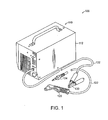
- FIG. 1 illustrates a plasma arc torch system 100 representative of any of a variety of models of torch systems, including hand cutting and mechanized cutting systems.
- a power supply 110 provides continuously variable current output within a range (e.g. from about 20 to 40 amperes). This range can be lower or higher depending on the torch system, the thickness of the work piece and the desired cutting speeds.
- the variable power supply 110 allows for wide variations in cutting speeds for a given thickness of metal.
- a torch body 120 configured for hand cutting is connected to the power supply 110 by a lead 122.
- the power supply 110 is enclosed by a housing 112.
- the lead 122 is connected to the power supply 110 by a strain relief system 124.
- the lead 122 provides the torch body 120 with a plasma gas from a gas source (not shown) and electrical power from the power supply 110 to ignite and sustain a plasma arc.
- a gas source not shown
- air is used as the plasma gas, but other gases can be used to improve cut quality on metals such as stainless steel and aluminum.
- a clamp 130 connects to a workpiece 250 ( FIG. 2 ) through a workpiece lead 132 to provide a return path for the current generated by the power supply 110.
- FIG. 2 illustrates in simplified schematic form the plasma arc torch body of FIG. 1 , representative of any of a variety of models of torches.
- the torch body 120 is generally cylindrical with an exit orifice 200 for allowing a plasma arc 240, i.e. an ionized gas jet, to be created between the torch body 120 and a workpiece 250.
- the torch is used to pierce and cut metal, such as mild steel or other electrically-conducting materials, in a transferred arc mode.
- the torch operates with a reactive gas, such as oxygen or air, or a non-reactive gas, such as nitrogen or argon, as the plasma gas to form the transferred plasma arc.
- a reactive gas such as oxygen or air
- a non-reactive gas such as nitrogen or argon
- the torch body 120 supports an electrode 210 having an insert 212 in its lower end and a nozzle 220 spaced from the electrode 210.
- the nozzle 220 has a central orifice that defines the exit orifice 200.
- a swirl ring 230 is mounted to the torch body 120.
- the swirl ring 230 has a set of radially offset (or canted) gas distribution holes 232 that impart a tangential velocity component to the plasma gas flow causing it to swirl. This swirl creates a vortex that constricts the arc and stabilizes the position of the arc on the insert.
- the assembly and disassembly of some of the torch components can be accomplished without the need for tools.
- torch components that have typically included threads for engagement to adjacent components can be replaced by components that slideably engage the other plasma torch components through the structures described in greater detail below.
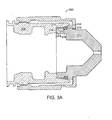
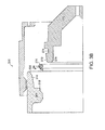
- FIGS. 3A and 3B show a simplified schematic and exploded diagram of a slidable nozzle 370 of a tool-tree plasma arc torch 300.
- the slidable nozzle 370 is maintained in an assembled position through the use of a retention cap 302 that, when attached, holds the slidable nozzle to an anode block 308 of the torch body 300. Conversely, when the retention cap 302 is removed, the slidable nozzle 370 can be removed without the need for any tools.
- a torch assembly as shown in FIG. 4 , can be created where a plurality of the torch components can be made to be slidably attached to the torch body, such that these components are coupled to the torch through the retention cap 302.
- the slidably components can be unassembled without the need for tools. Because these components can be slidably assembled, there is no need for threads to be included in these components in order to assemble to them to the torch body. Thus, both assembly time and manufacturing cost can be reduced.
- At least two torch components of a torch body are slidably coupled together such that in an assembled configuration, the two torch components (e.g., an anode 308 and a nozzle 370) are aligned in both a longitudinal direction and radial direction.
- the two torch components (308, 370) are also biased in an unassembled direction.
- the combination of alignment and biasing can be achieved by a number of embodiments and configuration, including the configuration described immediately below.
- the first torch component (308) and a second torch component (370) are aligned by a primary datum and a secondary datum with a compressible member (376) disposed between the two components (308, 370).
- the primary datum is an axial stop (318) in the first component (308), such that when assembled, the primary datum of the first component (308) abuts a corresponding feature or axial stop (378) in the second component (370).
- the axial stop may be a lip or edge in the first component (308) that engages a similar lip or edge in the second component (370) to establish the relative position of the two components along a longitudinal axis.
- the axial stop may be a hard or rigid axial stop such as created by a metal-to-metal contact.
- the secondary datum may be established by a tapered surface (314) in the first component (308) that aligns the first component (308) and the second component (370) in the radial direction through the compressible member (376).
- the compressible member (376) sits on the tapered surface (314) of the first component (308) and, when assembled, is compressed between the first component (308) and the second component (370).
- a compression vector is created having both an axial component (A) and a radial component (B).
- the radial component (B) serves to align the first component (308) and the second component (370) radially.
- the axial component (A) serves to bias the first component (308) and the second component (370) in an unassembled direction such that the two components (308, 370) freely disengage when the torch body (300) is being disassembled.
- the compression af the compressible member may also serve as a fluid seal between the first component (308) and second component (370).
- the secondary datum may be flexible. It should also be noted that the secondary datum may still allow for contact at a single point between the first component (308) and the second component (370) and still perform the aligning and biasing functions. Through the use of two datums, the first component (308) and the second component (370) are aligned in a manner that allows for ready disengagement and assembly.
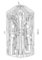
- FIG. 4 shows an embodiment of a lower body portion, or "working end” 400 of a liquid or gas cooled-type plasma arc torch as shown in FIGS. 1 and 2 .
- the working end 400 has a centrally disposed longitudinal axis 302 and includes a cathode block 304, a torch insulator 306, and an anode block 308, each block having respective tapered alignment surfaces 310, 312, 314.
- the cathode block 304 and the anode block 308 include respective axial stops 316, 318.
- the tapered alignment surface 308, 314 of the cathode block 304 and the anode block 308 can include respective lead-ins 322, 326 for protecting consumable components from damage during installation.
- the lead-ins 322, 326 are beneficial for component ejection by increasing axial force and reducing drag force on the components.
- the working end 400 further includes radially centered consumable components (an electrode 330, a swirl ring 350, a nozzle 370, and a shield 390).
- each tapered alignment surface 308, 312, 314 can further include a compressible member (not shown) for providing a seal, a radial alignment force, and an axial disengagement force between the torch and the consumable components.
- the torch is liquid or gas cooled.
- the electrode 330 includes a tapered surface 332 for aligning with the first tapered alignment surface 310 of the working end 400 of the plasma arc torch.
- the tapered surface 322 includes a feature (e.g. a recess) 334 or is dimensioned to receive a compressible member 336.
- the compressible member 336 such as an O-ring, provides the following functions: 1) a seal between the electrode 330 and the plasma chamber to contain and separate process gases and torch coolant; 2) a radial stop creating a radial alignment force for flexibly aligning the electrode 330 in the radial direction; and 3) an axial disengagement force between the working end 400 and the electrode 330 for biasing the electrode 330 in an unassembled direction.
- the tapered surface 332 has an axial extent of less than about 0.5 inches (1.27 cm) and, in some embodiments, less than about 0.25 inches (0.635 cm).
- the electrode 330 further includes an axial stop 338 for aligning the electrode 330 with the axial stop 316 of the cathode block 304.
- the axial stops 316, 338 are rigidly coupled. Further, axial-to-axial stop 316, 338 allows for conduction of electrical current and thermal energy needed to operate the torch. It should be understood that electrically coupling of the electrode 330 to the cathode block 304 can be accomplished in other manner known in the art.
- the tapered surface 332 is guided by the first tapered alignment surface 310 until the compressible member 336 comes to rest against first tapered alignment surface 310.
- the lead-in 322 on the first tapered alignment surface 310 prevents the compressible member or O-ring 336 from being damaged.
- a nominal clearance of 0.002 inches is provided between the taper surface 332 and the first tapered alignment surface 310 to prevent binding during installation.
- a swirl ring 350 can be disposed between the electrode 330 and the nozzle 370.
- the swirl ring 350 controls the fluid flow patterns on the plasma chamber front between the electrode 330 and the nozzle 370.
- the swirl ring 350 includes at least one feature (e.g. a recess) 354 or is dimensioned to receive a respective compressible member 356 for aligning with the second tapered alignment surface 312 of the working end 400 of the plasma arc torch.
- the compressible member 356, such as an O-ring provides the following functions: 1) a seal between the swirl ring 350 and the plasma chamber to contain and separate process gases and torch coolant; 2) a radial stop creating a radial alignment force for flexibly aligning the swirl ring 350 in the radial direction; and 3) an axial disengagement force between the working end 400 and the swirl ring 350 for biasing the swirl ring 350 in an unassembled direction.
- a spring element 358 is disposed between the electrode 330 and the swirl ring 350 to provide an engagement force of the electrode 330 and the cathode block 304 during installation. It should be understood that the spring element 358 can be disposed between the swirl ring 350 and the nozzle 370, integrated with the swirl ring 350, or provided in any configuration that provides engagement force of the electrode 330 to the cathode block 304.
- a non-integrated spring element 358 can be installed before or after the installation of the swirl ring 350 or in replacement of the swirl ring 350.
- the nozzle 370 includes a tapered surface 372 for aligning with the third tapered alignment surface 314 of the working end 400 of the plasma arc torch.
- the tapered surface 372 includes a feature (e.g. a recess) 374 or is dimensioned to receive a compressible member 355.
- the compressible member 376 such as an O-ring, provides the following functions: 1) a seal between the nozzle 370 and the plasma chamber to contain and separate process gases and torch coolant; 2) a radial stop creating a radial alignment force for flexibly aligning the nozzle 370 in the radial direction; and 3) an axial disengagement force between the working end 400 and the nozzle 370 for biasing the nozzle 370 in an unassembled direction.
- the tapered surface 372 has an axial extent of less than about 0.5 inches (1.27 cm).
- the nozzle 370 further includes an axial stop 378 for aligning the nozzle 370 with the axial stop 318 of the anode block 308.
- the axial stops 318, 378 are rigidly coupled. Further, axial-to-axial stop 318, 378 allows for conduction of electrical current and thermal energy needed to operate the torch. It should be understood that electrically coupling of the nozzle 370 to the anode block 308 can be accomplished in other manner known in the art.
- the tapered surface 372 is guided by the third tapered alignment surface 314 until the compressible member 376 comes to rest against third tapered alignment surface 314.
- the lead-in 326 on the third tapered alignment surface 314 prevents the compressible member or O-ring 376 from being damaged.
- a nominal clearance of 0.002 inches is provided between the taper surface 372 and the third tapered alignment surface 314 to prevent binding during installation.
- a hand-threaded retaining cap 302 may be employed to couple the consumables components to the torch body.
- the retaining cap 302 causes a force to be placed on the nozzle 370, the swirl ring 350, and the electrode 330 (through the spring element 358) that causes the longitudinal axis of these components to align with the torch axis 302.
- the force further seats these components with their respective counterparts of the working end 400 of the torch (e.g. the cathode block 304, the torch insulator 306, and the anode block 308).
- the shield 390 is typically the outermost component of the working end 400 of the torch.
- the shield 390 may be threadedly attached to the torch working end 400 or attached in a press-on configuration.
- shield 390 may be connected to the torch body by retain cap 392.
- the shield 390 may likewise include a tapered surface 372 for aligning with adjacent components.
- the tapered surface 372 may also include a feature (e.g. a recess) 374 to receive a compressible member 356.
- the shield 390 may serve to function as the retaining cap thereby providing the necessary force to seat the consumable components.
- the electrode 330, the swirl ring 350, the nozzle 370, and the shield 390 are subjected to harsh conditions, including high temperatures and other physical stresses. Consequently, these components degrade over time and eventually must be replaced, typically in the field. Prior techniques required the use of specialized tools to remove these components.
- the retaining cap 302 need only be removed by hand thereby allowing the axial component af the compression force on compressible members to assist in ejecting these components from the torch.
- FIG. 4 demonstrates an embodiment incorporating both tool-free and conventional torch components. That is, some components may be conventional type threaded consumables and some components may be slidable as described above. This allows for a reduction cost for the components that are more likely to be replaced than others. That is, the consumable components closest to the plasma arc are more likely to wear and need replacement before the components further from the plasma arc. For example, the electrode 330 and the nozzle 370 are more likely to wear before the shield 390, and the shield 390 is more likely to wear before the swirl ring 350, etc.
- the electrode 330 is threadedly attached to the cathode block 304 eliminating the need for the spring element 358 ( FIG. 3 ).
- the swirl ring 350, the nozzle 370, and the shield 390 are each coupled to the "working end" 400 of the plasma arc torch as mentioned above.
- the electrode 330 includes a threaded surface 339 and a deformable surface, such as a lip.
- the threaded surface 339 engages a cooperating thread 319 of the cathode block 304.
- the electrode 304 is axially aligned with the torch axis 302 and properly spaced from the nozzle 350 during torch operation.
- the engagement of the threaded surface 339 with the cooperating thread 319 also serves as an electrical connection to conduct the requisite current between the cathode block 304 and the electrode 330.
- the swirl ring 350 may also include a threaded surface that engages a cooperating threaded surface on the torch insulator 306. In general, however, the swirl ring 350 is simply captured in the working end 400 of the torch by the retention cap. In either configuration, it is desirable to center the swirl ring 350 about the electrode 330 so as to provide a concentric uniform annular plasma chamber to provide uniform gas flow therein and facilitate torch operation.
- FIGS. 3 and 4 show each tapered surface as a linear taper surface, however it should be understood that each tapered surface can be any number of shapes, including contoured surfaces and arcs.
- shape of the "tapered" surface can be understood to be any shape such that when two torch components are assembled, the tangent to the surface at the point of contact with compressible member is angled in the unassembled direction relative to the torch axis.
- the working end provides a simple and effective way to ensure the proper alignment of consumable components in the working end of a plasma arc torch.
- the problems of securing the critical alignments while operating under harsh field conditions, compounded by the need to replace components as they deteriorate from use, are largely eliminated. This avoids the unacceptable production errors affecting workpieces caused by improperly aligned apparatus and facilitates quick and easy replacement of the consumable components.
Landscapes
- Physics & Mathematics (AREA)
- Engineering & Computer Science (AREA)
- Plasma & Fusion (AREA)
- Spectroscopy & Molecular Physics (AREA)
- Geometry (AREA)
- Plasma Technology (AREA)
- Arc Welding In General (AREA)
Abstract
Description
- Plasma arc torches are widely used in the cutting, welding, and heat treating of metallic materials. A plasma arc torch generally includes a cathode block with an electrode mounted therein, a nozzle with a central exit orifice mounted within a torch body, electrical connections, passages for cooling and arc control fluids, a swirl ring to control fluid flow patterns in the plasma chamber formed between the electrode and nozzle, and a power supply. Sustaining a plasma arc causes the electrode, nozzle, swirl ring, and shield to wear requiring routine replacement; as such, the component parts are known as "consurtaables".
- Gas cooled plasma cutting torches exist which allow the consumable component parts to be changed without requiring tools. However, these gas cooled torches commonly use the same fluid (e.g, air) to support the cutting process and to cool the torch. Because only a single gas is used in such torches, there is less of a need to segregate the different gases between the various torch components (through the use of seals, o-rings, and the like). As a result of generally looser alignment of the components, gas cooled torches tend to be generally easy to disassemble.
- Liquid cooled torches, by comparison, require tight seals for segregating the different fluids/gases between the torch components. While these seals effectively control the fluid/gas flow between the different torch components, they also tend to hold the torch components tightly together. As a result, liquid cooled plasma cutting torches commonly require a specially designed tool to install and remove each consumable component part. For example, a specially designed tool is needed to install and remove the electrode, while another specially designed tool is needed to install and remove the nozzle, etc.
- Various factors facilitate the need for these specially designed tools. One factor includes the size of the consumable component part. For example, many consumable component parts have outside diameters less than 1 inch (2.54 cm) in size, making it difficult to generate enough torque to install and remove the consumable component parts by hand. Another factor includes precision alignment of the consumable component parts which requires small clearances between the mating diameters of the parts and the torch body. For example, part designs with tight radial clearances frequently do not freely mate with the torch body, Yet another factor includes incorporating seals, such as O-ring seals, in the consumable component part designs for containing and separating the liquid coolant and the process gases. Installing or removing consumable component parts with o-ring seals requires a force component to overcome the frictional drag force of the o-ring on the sealing surface.
- These specially designed tools add cost to the system and complicate system usage. In addition, features must be added to the consumable component parts to interface with the tools adding to the overall cost of the parts.
- Accordingly, a need exists to provide low-cost, readily-manufacturable, and easily-replaceable consumable components in a plasma arc torch, where the alignment and concentricity of the consumable components in the plasma arc torch can be closely controlled.
- A component for a plasma arc torch includes a body portion, a tapered surface on the body portion, the tapered surface including a compressible member that provides a disengagement force relative to the body portion, and an axially disposed surface on the body portion for coupling to a mating surface on an adjacent structure of the torch. The component can be a nozzle and/or an electrode. The plasma arc torch can be liquid or gas cooled.
- The compressible member can radially align the body portion with a central axis of the torch. The compressible member can provide a seal between the body portion and the torch. The compressible member can be an O-ring.
- In one embodiment, the tapered surface on the body portion can have a clearance in the range oaf 0.00001 inches (0.000254 mm) to a value above zero with respect to a respective tapered surface of the torch. In another embodiment, the tapered surface may be touching at a point about the circumference of the body portion. The tapered surface can include a feature for receiving the compressible member, wherein the feature can be a recess defined by the body portion.
- The axially disposed surface can be electrically coupled to the mating surface. The axially disposed surface can axially align the body portion in an axial position relative to the adjacent structure of the torch.
- In another embodiment, a tool-free plasma torch includes a torch body, an electrode coupled to the torch body, a nozzle coupled to the torch body, the nozzle having a tapered surface including a compressible member that provides a disengagement force relative to an adjacent tapered surface of the torch body, and an axially disposed surface for coupling a mating surface on an adjacent structure of the torch body, and a retention cap coupled to the torch body to provide an engagement force for coupling the nozzle to the torch body. The electrode can further include a tapered surface including the compressible member for providing a disengagement force relative to an adjacent tapered surface of the torch body and an axially disposed surface for coupling a mating surface on an adjacent structure of the torch body.
- The tool-free plasma torch can further include a spring element disposed between the electrode and the nozzle for providing a coupling force between the electrode and the torch body. The tool-free plasma torch can further include a swirl ring that includes a compressible member for providing a disengagement force relative to a tapered surface of the torch body. The spring element can be integrated with a swirl ring.
- The compressible members can align at least one of the electrode, the nozzle, and the swirl ring with a central axis of the torch. The electrode and the swirl ring can be fixedly coupled to the torch body. The electrode and the nozzle can be electrically coupled to a cathode and an anode of the torch body, respectively. The shield can be hand tightened to the torch body.
- In another embodiment, a plasma torch component can include a body portion, a tapered surface on the body portion dimensioned to receive a compressible member that provides a disengagement force relative to the body portion, an axially disposed surface on the body portion for aligning the body in an axial position relative to an adjacent structure of the torch and a mating surface for electrically coupling the component on the adjacent structure of the torch.
- In another embodiment, a plasma torch component can include a body portion having an axial length and a radial width, an axial stop for aligning the body portion in the direction of the axial length, and a tapered surface on the body portion dimensioned to engage a compressible member, wherein when the component is assembled the compressible member creates a force having an axial direction and a radial direction, wherein the radial direction of the force aligns the component radially and the axial direction of the force biases the component in an unassembled direction.
- In another embodiment, a plasma torch component can include a first component, an axial stop for rigidly aligning the first component in an axial direction relative to a second component, and a radial stop for flexibly aligning the first component in a radial direction relative to the second component and for biasing the first component in the axial direction. The first component can be a plasma torch body.
- A method for aligning a first component in a plasma torch assembly, the first component having an axial stop and a tapered surface for engaging a compressible member, the method can include slideably engaging the axial stop of the first component to a second component of the plasma torch assembly to position the second component in an axial direction and biasing the compressible member against the tapered surface of the first component to radially align the first component to the second component.
- In another embodiment, an assembly of plasma torch components can include a first component having an axial disposed surfaces and a tapered surface, a second component having an axial disposed surfaces, wherein the first component and the second component are aligned axially by their respective axial disposed surfaces, and a compression member aligning the first component and the second component radially, the compression member engaging the tapered surface such that the first component and the second component are biased in a direction of disassembly.
- Advantages of the apparatus include high precision consumable component parts that are easily changeable without tools leading to reduce the overall system cost and ease of system usage.
- Further embodiments of the invention are set art in the following nunbered paragraph: -
- 1. A component for a plasma arc torch, comprising:
- a body portion;
- a tapered surface on the body portion, the tapered surface including a compressible member that provides a disengagement force relative to the body portion; and
- an axially disposed surface on the body portion for coupling to a mating surface on an adjacent structure of the torch.
- 2. The component of paragraph 1, wherein the component is one of nozzle, a shield, a swirl ring, an electrode, or a portion of a body of the plasma arc torch.
- 3. The component of paragraph 1, wherein the compressible member radially aligns the body portion with a central axis of the torch.
- 4. The component of paragraph 1, wherein the tapered surface on the body portion has a clearance in the range of 0.00001 to 0.002 inches (0.000254 to 0.0508 mm) with respect to a respective tapered surface of the torch.
- 5. The component of paragraph 1, wherein the compressible member provides a seal between the body portion and the torch.
- 6. The component of paragraph 1, wherein the compressible member is an O-ring.
- 7. The component of paragraph 1, wherein the tapered surface includes a feature for receiving the compressible member.
- 8. The component of paragraph 7, wherein the feature on the tapered surface is a recess defined by the body portion.
- 9. The component of paragraph 1, wherein the axial disposed surface and the mating surface on the adjacent structure of the torch are electrically coupled.
- 10. The component of paragraph 1, wherein the axial disposed surface axially aligns the body portion in an axial position relative to the adjacent structure of the torch.
- 11. A plasma torch; comprising:
- a torch body;
- an electrode coupled to the torch body;
- a nozzle coupled to the torch body, the nozzle including:
- a tapered surface including a compressible member providing a disengagement force relative to an adjacent tapered surface of the torch body; and
- an axially disposed surface for coupling to a mating surface on an adjacent structure within the torch body; and
- a retaining cap coupled to the torch body, the retaining cap providing an engagement force for coupling the nozzle to torch body.
- 12. The plasma torch of paragraph 11, wherein electrode further including:
- a tapered surface including a compressible member, the compressible member providing a disengagement force relative to an adjacent tapered surface of the torch body; and
- an axially disposed surface for coupling a mating surface on an adjacent structure of the torch body.
- 13. The plasma torch of paragraph 12, further including a spring element disposed between the electrode and the nozzle for seating the electrode to the torch body when assembled.
- 14. The plasma torch of paragraph 13, further comprising a swirl ring disposed between the electrode and the nozzle, the swirl ring including a compressible member for providing a disengagement force relative to an adjacent tapered surface of the torch body.
- 15. The plasma torch of paragraph 14, wherein the spring element is integrated with the swirl ring.
- 16. The plasma torch of paragraph 11, wherein the tapered surfaces have a clearance in the range of 0,00001 to 0.002 inches (0.000254 to 0.0508 mm) with respect to the tapered surfaces of the torch.
- 17. The plasma torch of paragraph 11, wherein the tapered surfaces of the torch include a lead-in feature for protecting the compressible members from damage during installation.
- 18. The plasma torch of paragraph 11, wherein the compressible members align at least of the electrode, the nozzle, and the swirl ring with a central axis of the torch.
- 19. The plasma torch of paragraph 11, wherein the compressible member is an O-ring.
- 20. The plasma torch of paragraph 11, wherein the electrode is fixedly coupled to the torch body.
- 21. The plasma torch of paragraph 11, wherein the swirl ring is fixedly coupled to the torch body.
- 22. The plasma torch of paragraph 11, wherein the electrode is electrically coupled to a cathode of the torch body and the nozzle is electrically coupled to an anode of the torch body.
- 23. The plasma torch of paragraph 11, wherein the torch is liquid or gas cooled.
- 24. A component for a plasma arc torch, comprising:
- means for providing a disengagement force relative the component and the plasma arc torch; and
- means for engaging respective mating surfaces of the component and the plasma arc torch.
- 25. A plasma torch component, comprising:
- a body portion;
- a tapered surface on the body portion dimensioned to receive a compressible member that provides a disengagement force relative to the body portion;
- an axially disposed surface on the body portion for aligning the body in an axial position relative to an adjacent structure of the torch; and
- a mating surface for electrically coupling the component on the adjacent structure of the torch.
- 26. A plasma torch component, comprising:
- a body portion having an axial length and a radial width;
- an axial stop for aligning the body portion in the direction of the axial length; and
- a tapered surface on the body portion dimensioned to engage a compressible member, wherein when the component is assembled the compressible member creates a force having an axial direction and a radial direction, wherein the radial direction of the force aligns the component radially and the axial direction of the force biases the component in an unassembled direction.
- 27. A plasma torch component, comprising:
- a body;
- an axial stop defining a primary datum for rigidly aligning the body in an axial direction relative to an adjacent structure; and
- a radial stop defining a secondary datum for flexibly aligning the body in a radial direction relative to the adjacent structure and for biasing the body in the axial direction.
- 28. The component of paragraph 27, wherein the component is a plasma torch body.
- 29. A method for aligning a first component in a plasma torch assembly, the first component having an axial stop and a tapered surface for engaging a compressible member, the method comprising:
- slideably engaging the axial stop of the first component to a second component of the plasma torch assembly to position the second component relative to the first component in an axial direction; and
- biasing the compressible member against the tapered surface of the first component to radially align the first component to the second component.
- 30. An assembly of plasma torch components, the assembly comprising:
- a first component having an axial disposed surfaces and a tapered surface;
- a second component having an axial disposed surfaces, wherein the first component and the second component are aligned axially by their respective axial disposed surfaces; and
- a compression member aligning the first component and the second component radially, the compression member engaging the tapered surface such that the first component and the second component are biased in a direction of disassembly,
- 31. A method for aligning a first component of a plasma torch and a second component of a plasma torch assembly, having a compressible member disposed between the two components, the method comprising:
- axially aligning the first component to the second component by a rigid primary datum;
- radially aligning the first component to the second component by a flexible secondary datum, such that the compressible member aligns the first component and the second component radially and the compressible member axially biases the compressible member in an unassembled direction.
- The foregoing and other objects, features and advantages of the invention will be apparent from the following more particular description of preferred embodiments of the invention, as illustrated in the accompanying drawings in which like reference characters refer to the same parts throughout the different views. The drawings are not necessarily to scale, emphasis instead being placed upon illustrating the principles of the invention.
-
FIG. 1 illustrates a plasma arc torch system; -
FIG. 2 illustrates in simplified schematic form a plasma arc torch; -
FIG. 3A is a simplified schematic diagram of a tool-free plasma arc torch; -
FIG. 3B is an exploded view of the schematic diagram ofFIG. 3A ; -
FIG. 4 is a schematic diagram of a tool-free plasma arc torch; and -
FIG. 5 is a schematic diagram of another embodiment of the tool-free plasma arc torch ofFIG. 4 . -
FIG. 1 illustrates a plasmaarc torch system 100 representative of any of a variety of models of torch systems, including hand cutting and mechanized cutting systems. Apower supply 110 provides continuously variable current output within a range (e.g. from about 20 to 40 amperes). This range can be lower or higher depending on the torch system, the thickness of the work piece and the desired cutting speeds. Thevariable power supply 110 allows for wide variations in cutting speeds for a given thickness of metal. - A
torch body 120 configured for hand cutting is connected to thepower supply 110 by alead 122. Thepower supply 110 is enclosed by ahousing 112. Thelead 122 is connected to thepower supply 110 by astrain relief system 124. Thelead 122 provides thetorch body 120 with a plasma gas from a gas source (not shown) and electrical power from thepower supply 110 to ignite and sustain a plasma arc. In one embodiment, air is used as the plasma gas, but other gases can be used to improve cut quality on metals such as stainless steel and aluminum. Aclamp 130 connects to a workpiece 250 (FIG. 2 ) through aworkpiece lead 132 to provide a return path for the current generated by thepower supply 110. -
FIG. 2 illustrates in simplified schematic form the plasma arc torch body ofFIG. 1 , representative of any of a variety of models of torches. Thetorch body 120 is generally cylindrical with anexit orifice 200 for allowing aplasma arc 240, i.e. an ionized gas jet, to be created between thetorch body 120 and aworkpiece 250. The torch is used to pierce and cut metal, such as mild steel or other electrically-conducting materials, in a transferred arc mode. The torch operates with a reactive gas, such as oxygen or air, or a non-reactive gas, such as nitrogen or argon, as the plasma gas to form the transferred plasma arc. - The
torch body 120 supports anelectrode 210 having aninsert 212 in its lower end and anozzle 220 spaced from theelectrode 210. Thenozzle 220 has a central orifice that defines theexit orifice 200. Aswirl ring 230 is mounted to thetorch body 120. In one embodiment, theswirl ring 230 has a set of radially offset (or canted) gas distribution holes 232 that impart a tangential velocity component to the plasma gas flow causing it to swirl. This swirl creates a vortex that constricts the arc and stabilizes the position of the arc on the insert. - Referring to
FIGS. 3A - 5 , the assembly and disassembly of some of the torch components can be accomplished without the need for tools. For example, torch components that have typically included threads for engagement to adjacent components can be replaced by components that slideably engage the other plasma torch components through the structures described in greater detail below. -
FIGS. 3A and3B show a simplified schematic and exploded diagram of aslidable nozzle 370 of a tool-treeplasma arc torch 300. Theslidable nozzle 370 is maintained in an assembled position through the use of aretention cap 302 that, when attached, holds the slidable nozzle to ananode block 308 of thetorch body 300. Conversely, when theretention cap 302 is removed, theslidable nozzle 370 can be removed without the need for any tools. - Moreover, a torch assembly, as shown in
FIG. 4 , can be created where a plurality of the torch components can be made to be slidably attached to the torch body, such that these components are coupled to the torch through theretention cap 302. Again, once the retainingcap 302 is removed the slidably components can be unassembled without the need for tools. Because these components can be slidably assembled, there is no need for threads to be included in these components in order to assemble to them to the torch body. Thus, both assembly time and manufacturing cost can be reduced. - As shown in
FIGS. 3A and3B , at least two torch components of a torch body are slidably coupled together such that in an assembled configuration, the two torch components (e.g., ananode 308 and a nozzle 370) are aligned in both a longitudinal direction and radial direction. The two torch components (308, 370) are also biased in an unassembled direction. The combination of alignment and biasing can be achieved by a number of embodiments and configuration, including the configuration described immediately below. - As shown, the first torch component (308) and a second torch component (370) are aligned by a primary datum and a secondary datum with a compressible member (376) disposed between the two components (308, 370). The primary datum is an axial stop (318) in the first component (308), such that when assembled, the primary datum of the first component (308) abuts a corresponding feature or axial stop (378) in the second component (370). The axial stop may be a lip or edge in the first component (308) that engages a similar lip or edge in the second component (370) to establish the relative position of the two components along a longitudinal axis. The axial stop may be a hard or rigid axial stop such as created by a metal-to-metal contact.
- The secondary datum may be established by a tapered surface (314) in the first component (308) that aligns the first component (308) and the second component (370) in the radial direction through the compressible member (376). In one embodiment, the compressible member (376) sits on the tapered surface (314) of the first component (308) and, when assembled, is compressed between the first component (308) and the second component (370). During compression of the compression member (376), a compression vector is created having both an axial component (A) and a radial component (B).
- The radial component (B) serves to align the first component (308) and the second component (370) radially. The axial component (A) serves to bias the first component (308) and the second component (370) in an unassembled direction such that the two components (308, 370) freely disengage when the torch body (300) is being disassembled. The compression af the compressible member may also serve as a fluid seal between the first component (308) and second component (370). Because the secondary datum is positioned at the location of the contact of the compressible member, the secondary datum may be flexible. It should also be noted that the secondary datum may still allow for contact at a single point between the first component (308) and the second component (370) and still perform the aligning and biasing functions. Through the use of two datums, the first component (308) and the second component (370) are aligned in a manner that allows for ready disengagement and assembly.
-
FIG. 4 shows an embodiment of a lower body portion, or "working end" 400 of a liquid or gas cooled-type plasma arc torch as shown inFIGS. 1 and2 . The workingend 400 has a centrally disposedlongitudinal axis 302 and includes acathode block 304, atorch insulator 306, and ananode block 308, each block having respective tapered alignment surfaces 310, 312, 314. Thecathode block 304 and theanode block 308 include respectiveaxial stops alignment surface cathode block 304 and theanode block 308 can include respective lead-ins ins end 400 further includes radially centered consumable components (anelectrode 330, aswirl ring 350, anozzle 370, and a shield 390). In some embodiments, each taperedalignment surface - The
electrode 330 includes atapered surface 332 for aligning with the firsttapered alignment surface 310 of the workingend 400 of the plasma arc torch. Thetapered surface 322 includes a feature (e.g. a recess) 334 or is dimensioned to receive acompressible member 336. Thecompressible member 336, such as an O-ring, provides the following functions: 1) a seal between theelectrode 330 and the plasma chamber to contain and separate process gases and torch coolant; 2) a radial stop creating a radial alignment force for flexibly aligning theelectrode 330 in the radial direction; and 3) an axial disengagement force between the workingend 400 and theelectrode 330 for biasing theelectrode 330 in an unassembled direction. In some embodiments, thetapered surface 332 has an axial extent of less than about 0.5 inches (1.27 cm) and, in some embodiments, less than about 0.25 inches (0.635 cm). Theelectrode 330 further includes anaxial stop 338 for aligning theelectrode 330 with theaxial stop 316 of thecathode block 304. In some embodiments, theaxial stops axial stop electrode 330 to thecathode block 304 can be accomplished in other manner known in the art. - During installation, as the
electrode 330 is installed in the workingend 400 of the plasma arc torch, thetapered surface 332 is guided by the firsttapered alignment surface 310 until thecompressible member 336 comes to rest against firsttapered alignment surface 310. The lead-in 322 on the firsttapered alignment surface 310 prevents the compressible member or O-ring 336 from being damaged. As shown, in one embodiment a nominal clearance of 0.002 inches is provided between thetaper surface 332 and the firsttapered alignment surface 310 to prevent binding during installation. - In some embodiments, a
swirl ring 350 can be disposed between theelectrode 330 and thenozzle 370. Theswirl ring 350 controls the fluid flow patterns on the plasma chamber front between theelectrode 330 and thenozzle 370. Theswirl ring 350 includes at least one feature (e.g. a recess) 354 or is dimensioned to receive a respectivecompressible member 356 for aligning with the secondtapered alignment surface 312 of the workingend 400 of the plasma arc torch. Thecompressible member 356, such as an O-ring, provides the following functions: 1) a seal between theswirl ring 350 and the plasma chamber to contain and separate process gases and torch coolant; 2) a radial stop creating a radial alignment force for flexibly aligning theswirl ring 350 in the radial direction; and 3) an axial disengagement force between the workingend 400 and theswirl ring 350 for biasing theswirl ring 350 in an unassembled direction. In some embodiments, aspring element 358 is disposed between theelectrode 330 and theswirl ring 350 to provide an engagement force of theelectrode 330 and thecathode block 304 during installation. It should be understood that thespring element 358 can be disposed between theswirl ring 350 and thenozzle 370, integrated with theswirl ring 350, or provided in any configuration that provides engagement force of theelectrode 330 to thecathode block 304. - During installation, as the
swirl ring 350 is installed in the workingend 400 of the plasma arc torch, thecompressible member 356 comes to rest against secondtapered alignment surface 312. It should be understood anon-integrated spring element 358 can be installed before or after the installation of theswirl ring 350 or in replacement of theswirl ring 350. - The
nozzle 370 includes atapered surface 372 for aligning with the thirdtapered alignment surface 314 of the workingend 400 of the plasma arc torch. Thetapered surface 372 includes a feature (e.g. a recess) 374 or is dimensioned to receive a compressible member 355. Thecompressible member 376, such as an O-ring, provides the following functions: 1) a seal between thenozzle 370 and the plasma chamber to contain and separate process gases and torch coolant; 2) a radial stop creating a radial alignment force for flexibly aligning thenozzle 370 in the radial direction; and 3) an axial disengagement force between the workingend 400 and thenozzle 370 for biasing thenozzle 370 in an unassembled direction. In some embodiments, thetapered surface 372 has an axial extent of less than about 0.5 inches (1.27 cm). Thenozzle 370 further includes anaxial stop 378 for aligning thenozzle 370 with theaxial stop 318 of theanode block 308. In some embodiments, theaxial stops axial stop nozzle 370 to theanode block 308 can be accomplished in other manner known in the art. - During installation, as the
nozzle 370 is installed in the workingend 400 of the plasma arc torch, thetapered surface 372 is guided by the thirdtapered alignment surface 314 until thecompressible member 376 comes to rest against thirdtapered alignment surface 314. The lead-in 326 on the thirdtapered alignment surface 314 prevents the compressible member or O-ring 376 from being damaged. As shown, in one embodiment a nominal clearance of 0.002 inches is provided between thetaper surface 372 and the thirdtapered alignment surface 314 to prevent binding during installation. - A hand-threaded
retaining cap 302 may be employed to couple the consumables components to the torch body. The retainingcap 302 causes a force to be placed on thenozzle 370, theswirl ring 350, and the electrode 330 (through the spring element 358) that causes the longitudinal axis of these components to align with thetorch axis 302. The force further seats these components with their respective counterparts of the workingend 400 of the torch (e.g. thecathode block 304, thetorch insulator 306, and the anode block 308). - The
shield 390 is typically the outermost component of the workingend 400 of the torch. In some embodiments, theshield 390 may be threadedly attached to thetorch working end 400 or attached in a press-on configuration. In other embodiments, shield 390 may be connected to the torch body by retain cap 392. In such embodiments, theshield 390 may likewise include atapered surface 372 for aligning with adjacent components. Thetapered surface 372 may also include a feature (e.g. a recess) 374 to receive acompressible member 356. In some embodiments, theshield 390 may serve to function as the retaining cap thereby providing the necessary force to seat the consumable components. - During torch operation, the
electrode 330, theswirl ring 350, thenozzle 370, and theshield 390 are subjected to harsh conditions, including high temperatures and other physical stresses. Consequently, these components degrade over time and eventually must be replaced, typically in the field. Prior techniques required the use of specialized tools to remove these components. In the above embodiment, the retainingcap 302 need only be removed by hand thereby allowing the axial component af the compression force on compressible members to assist in ejecting these components from the torch. -
FIG. 4 demonstrates an embodiment incorporating both tool-free and conventional torch components. That is, some components may be conventional type threaded consumables and some components may be slidable as described above. This allows for a reduction cost for the components that are more likely to be replaced than others. That is, the consumable components closest to the plasma arc are more likely to wear and need replacement before the components further from the plasma arc. For example, theelectrode 330 and thenozzle 370 are more likely to wear before theshield 390, and theshield 390 is more likely to wear before theswirl ring 350, etc. - In the embodiment, the
electrode 330 is threadedly attached to thecathode block 304 eliminating the need for the spring element 358 (FIG. 3 ). Theswirl ring 350, thenozzle 370, and theshield 390 are each coupled to the "working end" 400 of the plasma arc torch as mentioned above. - The
electrode 330 includes a threadedsurface 339 and a deformable surface, such as a lip. The threadedsurface 339 engages a cooperatingthread 319 of thecathode block 304. By threadedly attaching theelectrode 330 to thecathode block 304, theelectrode 304 is axially aligned with thetorch axis 302 and properly spaced from thenozzle 350 during torch operation. The engagement of the threadedsurface 339 with the cooperatingthread 319 also serves as an electrical connection to conduct the requisite current between thecathode block 304 and theelectrode 330. - In some embodiments, the
swirl ring 350 may also include a threaded surface that engages a cooperating threaded surface on thetorch insulator 306. In general, however, theswirl ring 350 is simply captured in the workingend 400 of the torch by the retention cap. In either configuration, it is desirable to center theswirl ring 350 about theelectrode 330 so as to provide a concentric uniform annular plasma chamber to provide uniform gas flow therein and facilitate torch operation. -
FIGS. 3 and4 show each tapered surface as a linear taper surface, however it should be understood that each tapered surface can be any number of shapes, including contoured surfaces and arcs. In general, the shape of the "tapered" surface can be understood to be any shape such that when two torch components are assembled, the tangent to the surface at the point of contact with compressible member is angled in the unassembled direction relative to the torch axis. - From the foregoing, it will be appreciated that the working end provides a simple and effective way to ensure the proper alignment of consumable components in the working end of a plasma arc torch. The problems of securing the critical alignments while operating under harsh field conditions, compounded by the need to replace components as they deteriorate from use, are largely eliminated. This avoids the unacceptable production errors affecting workpieces caused by improperly aligned apparatus and facilitates quick and easy replacement of the consumable components.
- While this invention has been particularly shown and described with references to preferred embodiments thereof, it will be understood by those skilled in the art that various changes in form and details may be made therein without departing from the scope of the invention encompassed by the appended claims.
Claims (15)
- A plasma torch component, comprising:a body portion having an axial length and a radial width;an axial stop for aligning the body portion in the direction of the axial length; anda surface on the body portion dimensioned to engage a compressible member;characterized in that when the component is assembled the compressible member creates a force having an axial direction and a radial direction, wherein the radial direction of the force aligns the component radially and the axial direction of the force biases the component in an unassembled direction.
- The plasma torch component of claim 1, wherein any one or more of the following applies:a) the component is consumable;b) the axial stop is for aligning the body portion in the direction of the axial length when the consumable component is assembled in the plasma torch;c) the compressible member contacts a tapered surface of an adjacent structure of the torch; ord) when the component is assembled in the plasma torch the compressible member creates a force having an axial direction and a radial direction, wherein the radial direction of the force aligns the component radially and the axial direction of the force biases the component in an unassembled direction such that the consumable component freely disengages without the need for tools during disassembly of the plasma torch.
- The plasma torch component of claim 1 or claim 2, wherein any one or more of the following applies;a) the component is one of a nozzle, shield, swirl ring or an electrode;b) the adjacent structure of the torch is one of a nozzle, shield, swirl ring, an electrode, or a portion of a body of the plasma torch;c) the engagement surface is tapered; ord) the engagement surface on the body portion is dimensioned to receive the compressible member.
- A method for aligning a first component in a plasma torch assembly, the first component having an axial stop and a surface dimensioned to engage a compressible member, the method comprising:slideably engaging the axial stop of the first component to a second component of the plasma torch assembly to position the second component relative to the first component in an axial direction; andbiasing the compressible member against the engagement surface of the first component to radially align the first component to the second component.
- The method of claim 4 wherein the method comprises biasing the compressible member against the engagement surface of the first component and a tapered surface of the second component to create a force having an axial direction and a radial direction, wherein the radial direction of the force aligns the first and second components radially, and wherein the axial direction of the force biases the first component in an unassembled direction relative to the second component such that the first component freely disengages without the need for tools during disassembly of the plasma torch assembly.
- The method of any of claims 4 to 6 further comprising providing, via the compressible member, a seal between the first component and the second component.
- The method of any of claims 4 to 6 whereina) the first component is a consumable component; orb) the second component is a consumable component.
- The method of any of claims 4 to 7, wherein the compressible member is an O-ring.
- An assembly of plasma torch components, the assembly comprising:a first component having an axial disposed surface and a first engagement surface;a second component having an axial disposed surface, wherein the first component and the second component are aligned axially by their respective axial disposed surfaces anda compression member aligning the first component and the second component radially, the compression member engaging the first engagement surface such that the first component and the second component are biased in a direction of disassembly.
- The assembly of claim 9 wherein any one or more of the following applies;a) one of the first and second the plasma torch components is a nozzle, shield, swirl ring or electrode;b) the second component has an axial disposed surface and a second engagement surface;c) at least one of the first and second engagement surfaces is tapered; ord) the second component has an axial disposed surface and a second engagement surface and at least one of the first and second engagement surfaces is tapered.
- The assembly of claim 9 or claim 10 wherein the compression member aligns the first component and the second component radially, the compression member engaging the engagement surfaces to bias the first component and the second component in a direction of disassembly, such that the first component and second component freely disengage without the need for tools during disassembly of the plasma torch assembly.
- The assembly of any of claims 9 to 11, wherein any one or more of the following applies;a) the first component is one of a nozzle, shield, swirl ring or an electrode;b) the second component is one of a nozzle, shield, swirl ring or an electrode;c) the compressible member is an O-ring; ord) the compressible member provides a seal between the first component and the second component.
- A method for aligning a first component and a second component of a plasma torch assembly having a compressible member disposed between the two components, the method comprising:axially aligning the first component to the second component by a rigid primary datum;radially aligning the first component to the second component by a flexible secondary datum, wherein the compressible member aligns the first component and the second component radially and wherein the compressible member axially biases the compressible member in an unassembled direction such that the first component and second component freely disengage without the need for tools during disassembly of the plasma torch assembly.
- The method of claim 13 wherein the compressible member axially biases the compressible member in an unassembled direction such that the first component and second component freely disengage without the need for tools during disassembly of the plasma torch assembly.
- The method of claim 13 wherein any one or more of the following applies;a) one of the first and second the plasma torch components is a nozzle, shield, swirl ring or electrode;b) the second component has an axial disposed surface and a second engagement surface;c) the second component has an engagement surface that is tapered; ord) the second component has an axial disposed surface and an engagement surface that is tapered.
Applications Claiming Priority (2)
| Application Number | Priority Date | Filing Date | Title |
|---|---|---|---|
| US11/626,191 US8866038B2 (en) | 2007-01-23 | 2007-01-23 | Consumable component parts for a plasma torch |
| EP08250275A EP1951007B1 (en) | 2007-01-23 | 2008-01-22 | Consumable component parts for a plasma torch |
Related Parent Applications (2)
| Application Number | Title | Priority Date | Filing Date |
|---|---|---|---|
| EP08250275.8 Division | 2008-01-22 | ||
| EP08250275A Division EP1951007B1 (en) | 2007-01-23 | 2008-01-22 | Consumable component parts for a plasma torch |
Publications (2)
| Publication Number | Publication Date |
|---|---|
| EP2339898A2 true EP2339898A2 (en) | 2011-06-29 |
| EP2339898A3 EP2339898A3 (en) | 2016-06-01 |
Family
ID=39313030
Family Applications (2)
| Application Number | Title | Priority Date | Filing Date |
|---|---|---|---|
| EP11150336.3A Ceased EP2339898A3 (en) | 2007-01-23 | 2008-01-22 | Consumable component parts for a plasma torch |
| EP08250275A Revoked EP1951007B1 (en) | 2007-01-23 | 2008-01-22 | Consumable component parts for a plasma torch |
Family Applications After (1)
| Application Number | Title | Priority Date | Filing Date |
|---|---|---|---|
| EP08250275A Revoked EP1951007B1 (en) | 2007-01-23 | 2008-01-22 | Consumable component parts for a plasma torch |
Country Status (8)
| Country | Link |
|---|---|
| US (2) | US8866038B2 (en) |
| EP (2) | EP2339898A3 (en) |
| KR (1) | KR101288658B1 (en) |
| CN (2) | CN101543139B (en) |
| AT (1) | ATE522121T1 (en) |
| BR (1) | BRPI0800180B1 (en) |
| CA (1) | CA2674639C (en) |
| WO (1) | WO2008091735A1 (en) |
Cited By (1)
| Publication number | Priority date | Publication date | Assignee | Title |
|---|---|---|---|---|
| WO2013114007A1 (en) | 2012-02-01 | 2013-08-08 | L'air Liquide,Societe Anonyme Pour L'etude Et L'exploitation Des Procedes Georges Claude | Plasma arc torch with improved axial centring of the electrode |
Families Citing this family (36)
| Publication number | Priority date | Publication date | Assignee | Title |
|---|---|---|---|---|
| US10098217B2 (en) | 2012-07-19 | 2018-10-09 | Hypertherm, Inc. | Composite consumables for a plasma arc torch |
| US10194516B2 (en) | 2006-09-13 | 2019-01-29 | Hypertherm, Inc. | High access consumables for a plasma arc cutting system |
| US9662747B2 (en) | 2006-09-13 | 2017-05-30 | Hypertherm, Inc. | Composite consumables for a plasma arc torch |
| US9560732B2 (en) * | 2006-09-13 | 2017-01-31 | Hypertherm, Inc. | High access consumables for a plasma arc cutting system |
| US8866038B2 (en) | 2007-01-23 | 2014-10-21 | Hypertherm, Inc. | Consumable component parts for a plasma torch |
| TWI352368B (en) * | 2007-09-21 | 2011-11-11 | Ind Tech Res Inst | Plasma head and plasma-discharging device using th |
| US8395070B2 (en) | 2010-04-01 | 2013-03-12 | American Torch Tip | Electrical contact point device for use in a plasma arc cutting torch |
| WO2012118834A1 (en) * | 2011-02-28 | 2012-09-07 | Thermal Dynamics Corporation | Plasma cutting tip with advanced cooling passageways |
| KR101251471B1 (en) * | 2011-04-07 | 2013-04-05 | 현대삼호중공업 주식회사 | Structure for assembly plasma torch and guard cap |
| US8901451B2 (en) * | 2011-08-19 | 2014-12-02 | Illinois Tool Works Inc. | Plasma torch and moveable electrode |
| US11783138B2 (en) | 2012-04-04 | 2023-10-10 | Hypertherm, Inc. | Configuring signal devices in thermal processing systems |
| US10716199B2 (en) * | 2013-07-25 | 2020-07-14 | Hypertherm, Inc. | Devices for gas cooling plasma arc torches and related systems and methods |
| US9609733B2 (en) | 2013-11-12 | 2017-03-28 | The Esab Group, Inc. | Plasma arc torch and method for assembling and disassembling a plasma arc torch |
| US12521905B2 (en) | 2014-03-07 | 2026-01-13 | Hypertherm, Inc. | Liquid pressurization pump and systems with data storage |
| WO2015132657A1 (en) * | 2014-03-07 | 2015-09-11 | Lincoln Global Inc. | Apparatus of sealing and securing components of a liquid cooled plasma arc torch and improved torch design |
| US9572243B2 (en) * | 2014-05-19 | 2017-02-14 | Lincoln Global, Inc. | Air cooled plasma torch and components thereof |
| CN103997841B (en) * | 2014-05-30 | 2016-04-27 | 南京工业大学 | Hand-held portable sliding arc low-temperature plasma generating device |
| CN103997840B (en) * | 2014-05-30 | 2016-04-27 | 南京工业大学 | Hand-held portable sliding arc low-temperature plasma generating device |
| AU2015301727B2 (en) | 2014-08-12 | 2020-05-14 | Hypertherm, Inc. | Cost effective cartridge for a plasma arc torch |
| CN104378903B (en) * | 2014-11-11 | 2017-07-28 | 衢州昀睿工业设计有限公司 | A cathode with a microporous membrane structure |
| JP6522968B2 (en) * | 2015-01-30 | 2019-05-29 | 株式会社小松製作所 | Insulation guide for plasma torch and replacement part unit |
| JP6522967B2 (en) * | 2015-01-30 | 2019-05-29 | 株式会社小松製作所 | Center pipe for plasma torch, contactor, electrode, and plasma torch |
| US10555410B2 (en) * | 2015-08-04 | 2020-02-04 | Hypertherm, Inc. | Cartridge for a liquid-cooled plasma arc torch |
| US10440808B2 (en) | 2015-11-17 | 2019-10-08 | Southwest Research Institute | High power impulse plasma source |
| US10354845B2 (en) * | 2016-02-18 | 2019-07-16 | Southwest Research Institute | Atmospheric pressure pulsed arc plasma source and methods of coating therewith |
| RU175548U1 (en) * | 2016-03-28 | 2017-12-08 | Гипертерм, Инк. | ADVANCED SYSTEM FOR PLASMA-ARC CUTTING, CONSUMABLE COMPONENTS AND METHODS OF WORK |
| WO2018148496A1 (en) * | 2017-02-09 | 2018-08-16 | Hypertherm, Inc. | Swirl ring and contact element for a plasma arc torch cartridge |
| US10917961B2 (en) * | 2017-09-13 | 2021-02-09 | Lincoln Global, Inc. | High temperature isolating insert for plasma cutting torch |
| US11267069B2 (en) | 2018-04-06 | 2022-03-08 | The Esab Group Inc. | Recognition of components for welding and cutting torches |
| US20190358730A1 (en) * | 2018-04-06 | 2019-11-28 | The Esab Group Inc. | Automatic identification of components for welding and cutting torches |
| CN110303228B (en) * | 2019-06-10 | 2021-08-03 | 日照唐晟锯业有限公司 | Cutting nozzle for plasma cutting machine |
| EP3782760A1 (en) * | 2019-08-22 | 2021-02-24 | Linde GmbH | Torch for arc welding or cutting and method using said torch |
| CZ2019652A3 (en) * | 2019-10-21 | 2020-12-16 | Thermacut, K.S. | A part of a cutting or welding torch comprising a thread |
| US11839015B2 (en) | 2021-02-04 | 2023-12-05 | The Esab Group Inc. | Consumables for processing torches |
| KR102838984B1 (en) * | 2024-06-12 | 2025-07-25 | 주식회사 넥스트에너지코퍼레이션 | Plasma generation apparatus |
| KR102711791B1 (en) * | 2024-06-12 | 2024-09-30 | 주식회사 넥스트에너지코퍼레이션 | Plasma generation apparatus |
Family Cites Families (13)
| Publication number | Priority date | Publication date | Assignee | Title |
|---|---|---|---|---|
| US4389559A (en) | 1981-01-28 | 1983-06-21 | Eutectic Corporation | Plasma-transferred-arc torch construction |
| US5317126A (en) * | 1992-01-14 | 1994-05-31 | Hypertherm, Inc. | Nozzle and method of operation for a plasma arc torch |
| US5841095A (en) | 1996-10-28 | 1998-11-24 | Hypertherm, Inc. | Apparatus and method for improved assembly concentricity in a plasma arc torch |
| US6156995A (en) * | 1998-12-02 | 2000-12-05 | The Esab Group, Inc. | Water-injection nozzle assembly with insulated front end |
| US6848111B1 (en) * | 1999-02-02 | 2005-01-25 | Sun Microsystems, Inc. | Zero overhead exception handling |
| US6320156B1 (en) * | 1999-05-10 | 2001-11-20 | Komatsu Ltd. | Plasma processing device, plasma torch and method for replacing components of same |
| US6424082B1 (en) * | 2000-08-03 | 2002-07-23 | Hypertherm, Inc. | Apparatus and method of improved consumable alignment in material processing apparatus |
| US6979796B1 (en) | 2003-02-27 | 2005-12-27 | Innerlogic, Inc. | Method and apparatus for proper alignment of components in a plasma arc torch |
| US6946617B2 (en) * | 2003-04-11 | 2005-09-20 | Hypertherm, Inc. | Method and apparatus for alignment of components of a plasma arc torch |
| JP2005329434A (en) | 2004-05-20 | 2005-12-02 | Koike Sanso Kogyo Co Ltd | Electrode for plasma torch |
| JP4688450B2 (en) | 2004-08-16 | 2011-05-25 | 株式会社小松製作所 | Plasma processing machine, plasma torch and method for attaching / detaching the parts |
| CN2845398Y (en) * | 2005-10-25 | 2006-12-06 | 天津大学机电工厂 | The air plasma arc cutting torch |
| US8866038B2 (en) | 2007-01-23 | 2014-10-21 | Hypertherm, Inc. | Consumable component parts for a plasma torch |
-
2007
- 2007-01-23 US US11/626,191 patent/US8866038B2/en active Active
-
2008
- 2008-01-10 KR KR1020097015407A patent/KR101288658B1/en active Active
- 2008-01-10 CN CN200880000188.2A patent/CN101543139B/en active Active
- 2008-01-10 CA CA2674639A patent/CA2674639C/en active Active
- 2008-01-10 CN CN2013101856363A patent/CN103260331A/en active Pending
- 2008-01-10 WO PCT/US2008/050692 patent/WO2008091735A1/en not_active Ceased
- 2008-01-22 BR BRPI0800180-4A patent/BRPI0800180B1/en active IP Right Grant
- 2008-01-22 EP EP11150336.3A patent/EP2339898A3/en not_active Ceased
- 2008-01-22 AT AT08250275T patent/ATE522121T1/en not_active IP Right Cessation
- 2008-01-22 EP EP08250275A patent/EP1951007B1/en not_active Revoked
-
2020
- 2020-10-02 US US17/062,337 patent/USRE49153E1/en active Active
Non-Patent Citations (1)
| Title |
|---|
| None |
Cited By (1)
| Publication number | Priority date | Publication date | Assignee | Title |
|---|---|---|---|---|
| WO2013114007A1 (en) | 2012-02-01 | 2013-08-08 | L'air Liquide,Societe Anonyme Pour L'etude Et L'exploitation Des Procedes Georges Claude | Plasma arc torch with improved axial centring of the electrode |
Also Published As
| Publication number | Publication date |
|---|---|
| BRPI0800180A (en) | 2008-09-16 |
| ATE522121T1 (en) | 2011-09-15 |
| EP1951007A1 (en) | 2008-07-30 |
| CA2674639A1 (en) | 2008-07-31 |
| KR101288658B1 (en) | 2013-07-22 |
| EP1951007B1 (en) | 2011-08-24 |
| KR20090103921A (en) | 2009-10-01 |
| USRE49153E1 (en) | 2022-07-26 |
| CN101543139B (en) | 2014-05-14 |
| CA2674639C (en) | 2015-09-01 |
| CN103260331A (en) | 2013-08-21 |
| US20080173622A1 (en) | 2008-07-24 |
| US8866038B2 (en) | 2014-10-21 |
| BRPI0800180B1 (en) | 2015-07-28 |
| CN101543139A (en) | 2009-09-23 |
| EP2339898A3 (en) | 2016-06-01 |
| WO2008091735A1 (en) | 2008-07-31 |
Similar Documents
| Publication | Publication Date | Title |
|---|---|---|
| USRE49153E1 (en) | Consumable component parts for a plasma torch | |
| CN101884253B (en) | Method and apparatus for alignment of components of plasma arc torch | |
| EP1621052B1 (en) | Method and apparatus for alignment of components of a plasma arc torch | |
| US8901451B2 (en) | Plasma torch and moveable electrode | |
| US20020135283A1 (en) | Nozzle for plasma arc torch | |
| EP2147583B1 (en) | Plasma arc torch cutting component with optimized water cooling | |
| CN101632328B (en) | Gas-cooled plasma arc cutting torch | |
| US7935909B2 (en) | Hybrid shield device for a plasma arc torch | |
| EP2029309B1 (en) | Plasma arc torch cutting component with optimized water cooling | |
| JP2006523006A5 (en) | ||
| US6888093B2 (en) | Apparatus for proper alignment of components in a plasma arc torch | |
| CZ296337B6 (en) | Device with plasma torch | |
| US20250058401A1 (en) | Arc processing torch with consumable | |
| JP7833386B2 (en) | welding torch |
Legal Events
| Date | Code | Title | Description |
|---|---|---|---|
| PUAI | Public reference made under article 153(3) epc to a published international application that has entered the european phase |
Free format text: ORIGINAL CODE: 0009012 |
|
| AC | Divisional application: reference to earlier application |
Ref document number: 1951007 Country of ref document: EP Kind code of ref document: P |
|
| AK | Designated contracting states |
Kind code of ref document: A2 Designated state(s): AT BE BG CH CY CZ DE DK EE ES FI FR GB GR HR HU IE IS IT LI LT LU LV MC MT NL NO PL PT RO SE SI SK TR |
|
| RAP1 | Party data changed (applicant data changed or rights of an application transferred) |
Owner name: HYPERTHERM, INC. |
|
| PUAL | Search report despatched |
Free format text: ORIGINAL CODE: 0009013 |
|
| AK | Designated contracting states |
Kind code of ref document: A3 Designated state(s): AT BE BG CH CY CZ DE DK EE ES FI FR GB GR HR HU IE IS IT LI LT LU LV MC MT NL NO PL PT RO SE SI SK TR |
|
| RIC1 | Information provided on ipc code assigned before grant |
Ipc: H05H 1/34 20060101AFI20160422BHEP |
|
| 17P | Request for examination filed |
Effective date: 20161129 |
|
| RBV | Designated contracting states (corrected) |
Designated state(s): AT BE BG CH CY CZ DE DK EE ES FI FR GB GR HR HU IE IS IT LI LT LU LV MC MT NL NO PL PT RO SE SI SK TR |
|
| 17Q | First examination report despatched |
Effective date: 20190930 |
|
| STAA | Information on the status of an ep patent application or granted ep patent |
Free format text: STATUS: THE APPLICATION HAS BEEN REFUSED |
|
| 18R | Application refused |
Effective date: 20201109 |