JP6522967B2 - Center pipe for plasma torch, contactor, electrode, and plasma torch - Google Patents

Center pipe for plasma torch, contactor, electrode, and plasma torch Download PDF

Info

Publication number
JP6522967B2
JP6522967B2 JP2015017463A JP2015017463A JP6522967B2 JP 6522967 B2 JP6522967 B2 JP 6522967B2 JP 2015017463 A JP2015017463 A JP 2015017463A JP 2015017463 A JP2015017463 A JP 2015017463A JP 6522967 B2 JP6522967 B2 JP 6522967B2
Authority
JP
Japan
Prior art keywords
electrode
contact
nozzle
passage
plasma torch
Prior art date
Legal status (The legal status is an assumption and is not a legal conclusion. Google has not performed a legal analysis and makes no representation as to the accuracy of the status listed.)
Active
Application number
JP2015017463A
Other languages
Japanese (ja)
Other versions
JP2016140871A5 (en
JP2016140871A (en
Inventor
山口 義博
義博 山口
圭太 近藤
圭太 近藤
茂夫 森本
茂夫 森本
齋尾 克男
克男 齋尾
Current Assignee (The listed assignees may be inaccurate. Google has not performed a legal analysis and makes no representation or warranty as to the accuracy of the list.)
Komatsu Ltd
Komatsu Industries Corp
Original Assignee
Komatsu Ltd
Komatsu Industries Corp
Priority date (The priority date is an assumption and is not a legal conclusion. Google has not performed a legal analysis and makes no representation as to the accuracy of the date listed.)
Filing date
Publication date
Priority to JP2015017463A priority Critical patent/JP6522967B2/en
Application filed by Komatsu Ltd, Komatsu Industries Corp filed Critical Komatsu Ltd
Priority to US15/325,313 priority patent/US10232460B2/en
Priority to CN201580035372.0A priority patent/CN106660159B/en
Priority to KR1020197001231A priority patent/KR102042545B1/en
Priority to KR1020167036908A priority patent/KR101940595B1/en
Priority to DE112015003758.6T priority patent/DE112015003758B4/en
Priority to PCT/JP2015/084161 priority patent/WO2016121227A1/en
Priority to KR1020197001232A priority patent/KR102042546B1/en
Publication of JP2016140871A publication Critical patent/JP2016140871A/en
Priority to US16/264,838 priority patent/US11014188B2/en
Publication of JP2016140871A5 publication Critical patent/JP2016140871A5/ja
Application granted granted Critical
Publication of JP6522967B2 publication Critical patent/JP6522967B2/en
Active legal-status Critical Current
Anticipated expiration legal-status Critical

Links

Images

Classifications

    • BPERFORMING OPERATIONS; TRANSPORTING
    • B23MACHINE TOOLS; METAL-WORKING NOT OTHERWISE PROVIDED FOR
    • B23KSOLDERING OR UNSOLDERING; WELDING; CLADDING OR PLATING BY SOLDERING OR WELDING; CUTTING BY APPLYING HEAT LOCALLY, e.g. FLAME CUTTING; WORKING BY LASER BEAM
    • B23K10/00Welding or cutting by means of a plasma
    • HELECTRICITY
    • H05ELECTRIC TECHNIQUES NOT OTHERWISE PROVIDED FOR
    • H05HPLASMA TECHNIQUE; PRODUCTION OF ACCELERATED ELECTRICALLY-CHARGED PARTICLES OR OF NEUTRONS; PRODUCTION OR ACCELERATION OF NEUTRAL MOLECULAR OR ATOMIC BEAMS
    • H05H1/00Generating plasma; Handling plasma
    • H05H1/24Generating plasma
    • H05H1/26Plasma torches
    • H05H1/28Cooling arrangements
    • HELECTRICITY
    • H05ELECTRIC TECHNIQUES NOT OTHERWISE PROVIDED FOR
    • H05HPLASMA TECHNIQUE; PRODUCTION OF ACCELERATED ELECTRICALLY-CHARGED PARTICLES OR OF NEUTRONS; PRODUCTION OR ACCELERATION OF NEUTRAL MOLECULAR OR ATOMIC BEAMS
    • H05H1/00Generating plasma; Handling plasma
    • H05H1/24Generating plasma
    • H05H1/26Plasma torches
    • H05H1/32Plasma torches using an arc
    • H05H1/34Details, e.g. electrodes, nozzles
    • H05H1/3423Connecting means, e.g. electrical connecting means or fluid connections
    • HELECTRICITY
    • H05ELECTRIC TECHNIQUES NOT OTHERWISE PROVIDED FOR
    • H05HPLASMA TECHNIQUE; PRODUCTION OF ACCELERATED ELECTRICALLY-CHARGED PARTICLES OR OF NEUTRONS; PRODUCTION OR ACCELERATION OF NEUTRAL MOLECULAR OR ATOMIC BEAMS
    • H05H1/00Generating plasma; Handling plasma
    • H05H1/24Generating plasma
    • H05H1/26Plasma torches
    • H05H1/32Plasma torches using an arc
    • H05H1/34Details, e.g. electrodes, nozzles
    • H05H1/3436Hollow cathodes with internal coolant flow
    • HELECTRICITY
    • H05ELECTRIC TECHNIQUES NOT OTHERWISE PROVIDED FOR
    • H05HPLASMA TECHNIQUE; PRODUCTION OF ACCELERATED ELECTRICALLY-CHARGED PARTICLES OR OF NEUTRONS; PRODUCTION OR ACCELERATION OF NEUTRAL MOLECULAR OR ATOMIC BEAMS
    • H05H1/00Generating plasma; Handling plasma
    • H05H1/24Generating plasma
    • H05H1/26Plasma torches
    • H05H1/32Plasma torches using an arc
    • H05H1/34Details, e.g. electrodes, nozzles
    • H05H1/3457Nozzle protection devices

Description

本発明は、プラズマトーチ用センタパイプ、接触子、電極、及びプラズマトーチに関する。   The present invention relates to a center pipe for a plasma torch, a contact, an electrode, and a plasma torch.

プラズマトーチは、アークの発生点となる電極と、電極を被うように配置されるノズルとを有している。電極は、トーチ本体の電極台座に取り付けられる。ノズルは、絶縁ガイドを介して電極に取り付けられる。絶縁ガイドは、ノズルが電極と同心に配置されるようにノズルを位置決めする。プラズマトーチは、ノズルのオリフィスを通じて電極とワークとの間でプラズマアークを発生させる。   The plasma torch has an electrode serving as an arc generation point, and a nozzle arranged to cover the electrode. The electrode is attached to the electrode pedestal of the torch body. The nozzle is attached to the electrode via an insulating guide. The insulating guide positions the nozzle such that the nozzle is arranged concentric with the electrode. The plasma torch generates a plasma arc between the electrode and the work through the orifice of the nozzle.

電極は消耗品であるため、トーチ本体の電極台座に着脱可能に取り付けられる。例えば、特許文献1に示されているように、電極は、先端側筒部と、フランジ部と、基端側筒部とを有する。フランジ部は、先端側筒部及び基端側筒部よりも大きな外径を有する。基端側筒部が電極台座の内面と摩擦抵抗力によって接合することで、電極が電極台座に取り付けられる。或いは、電極台座には雌ネジ部が形成され、基端側筒部には、雄ネジ部が形成される。基端側筒部の雄ネジ部が、電極台座の雌ネジ部に螺合することにより、電極が電極台座に取り付けられる。   Since the electrode is a consumable item, it is removably attached to the electrode base of the torch body. For example, as disclosed in Patent Document 1, the electrode has a distal end side tubular portion, a flange portion, and a proximal end side tubular portion. The flange portion has an outer diameter larger than that of the distal end side tubular portion and the proximal end side tubular portion. The electrode is attached to the electrode base by joining the proximal end cylindrical portion to the inner surface of the electrode base by frictional resistance. Alternatively, a female screw portion is formed on the electrode base, and a male screw portion is formed on the proximal end cylindrical portion. The male screw portion of the proximal end cylindrical portion is screwed into the female screw portion of the electrode pedestal, whereby the electrode is attached to the electrode pedestal.

電極が電極台座に取り付けられた状態では、フランジ部の軸線方向における端面が、電極台座の先端部に接触する。また、基端側筒部の外周面が電極台座の内周面に接触する。すなわち、電極においては、基端側筒部の外周面と、フランジ部の軸線方向における端面とが、電極台座との通電面となっている。これらの通電面により、電極とトーチ本体とが電気的に接続される。   In the state where the electrode is attached to the electrode pedestal, the axial end face of the flange portion contacts the tip of the electrode pedestal. Further, the outer peripheral surface of the proximal end cylindrical portion contacts the inner peripheral surface of the electrode pedestal. That is, in the electrode, the outer peripheral surface of the proximal end cylindrical portion and the end surface in the axial direction of the flange portion form a current-carrying surface with the electrode pedestal. The electrodes and the torch body are electrically connected by these current-carrying surfaces.

特開2001−47247号公報JP, 2001-47247, A

上述したプラズマトーチでは、基端側筒部と電極台座の内周面とを接続するために、電極或いは電極台座の構造が複雑になるという問題がある。また、基端側筒部と電極台座とがネジ構造によって接続される場合には、電極の着脱に専用の工具が必要となる。さらに、通電不良により、基端側筒部と電極台座との通電面が損傷した場合には、プラズマトーチのトーチ本体を交換しなければならないという問題がある。   The above-described plasma torch has a problem that the structure of the electrode or the electrode base becomes complicated in order to connect the proximal end side cylindrical portion and the inner peripheral surface of the electrode base. In addition, when the proximal end cylindrical portion and the electrode pedestal are connected by a screw structure, a dedicated tool is required to attach and detach the electrode. Furthermore, there is a problem that the torch main body of the plasma torch has to be replaced when the current-carrying surfaces of the base end side cylindrical portion and the electrode pedestal are damaged due to poor current conduction.

本発明の課題は、専用の工具無しで容易に電極の着脱が可能であり、電極或いは電極台座の構造を簡素化することができ、さらに通電不良が生じてもトーチ本体の交換が不要なプラズマトーチ用センタパイプ、接触子、電極、及びプラズマトーチを提供することにある。   It is an object of the present invention that the electrode can be easily attached and detached without a dedicated tool, the structure of the electrode or the electrode base can be simplified, and the plasma does not need to be replaced It is providing a center pipe for torches, a contact, an electrode, and a plasma torch.

本発明の第1の態様に係るセンタパイプは、ベース部と電極とを有するプラズマ切断用のプラズマトーチに用いられる。センタパイプは、電極に挿入され、電極内に冷却水を供給する。センタパイプは、パイプ本体と接触子とを備える。パイプ本体は、ベース部を介してプラズマトーチ外の電源と電気的に接続される。パイプ本体は、冷却水通路を内部に有する。パイプ本体は、導電体で形成される。接触子は、パイプ本体の外周面に設けられ、電極の内周面に接触することで電極に通電する。接触子は、パイプ本体の径方向に押圧されることで反力を生じるように弾性を有する。接触子は、導電体で形成される。   The center pipe according to the first aspect of the present invention is used for a plasma torch for plasma cutting having a base portion and an electrode. The center pipe is inserted into the electrode and supplies cooling water into the electrode. The center pipe comprises a pipe body and a contact. The pipe body is electrically connected to the power supply outside the plasma torch through the base portion. The pipe body has a cooling water passage inside. The pipe body is formed of a conductor. The contact is provided on the outer peripheral surface of the pipe main body, and the electrode is energized by contacting the inner peripheral surface of the electrode. The contactor has elasticity so as to generate a reaction force by being pressed in the radial direction of the pipe body. The contacts are formed of a conductor.

接触子は、パイプ本体と別体であり、パイプ本体の外周面に取り付けられてもよい。   The contact is separate from the pipe body, and may be attached to the outer peripheral surface of the pipe body.

パイプ本体の外周面は、接触子が取り付けられる凹部を有してもよい。   The outer peripheral surface of the pipe body may have a recess in which the contact is attached.

接触子は、第1環部と、第2環部と、複数の湾曲部と、を有してもよい。第2環部は、接触子の軸線方向に第1環部から離れて配置されてもよい。複数の湾曲部は、第1環部と第2環部とを連結し、接触子の径方向外方に向かって膨出してもよい。   The contact may have a first ring portion, a second ring portion, and a plurality of curved portions. The second ring portion may be disposed apart from the first ring portion in the axial direction of the contact. The plurality of curved portions may connect the first ring portion and the second ring portion, and may bulge outward in the radial direction of the contact.

接触子は、複数の湾曲部の間に設けられ、接触子の軸線方向に延びる複数のスリットを有してもよい。   The contact may be provided between the plurality of curved portions and may have a plurality of slits extending in the axial direction of the contact.

本発明の第2の態様に係る接触子は、電極とパイプ本体とを有するプラズマ切断用のプラズマトーチに用いられる。パイプ本体は、電極に挿入される。パイプ本体は、電極内に冷却水を供給するための冷却水通路を内部に有する。接触子は、取付部と接触部とを備える。取付部は、パイプ本体の外周面に取り付けられる。接触部は、電極の内周面に接触する。   A contact according to a second aspect of the present invention is used in a plasma torch for plasma cutting having an electrode and a pipe body. The pipe body is inserted into the electrode. The pipe body internally has a cooling water passage for supplying cooling water into the electrode. The contact includes an attachment portion and a contact portion. The attachment portion is attached to the outer peripheral surface of the pipe body. The contact portion contacts the inner circumferential surface of the electrode.

接触部は、接触子の径方向に押圧されることで反力を生じるように弾性を有してもよい。   The contact portion may have elasticity so as to generate a reaction force by being pressed in the radial direction of the contact.

取付部は、第1環部と第2環部とを有してもよい。第2環部は、接触子の軸線方向に第1環部から離れて配置されてもよい。接触部は、複数の湾曲部を有してもよい。複数の湾曲部は、第1環部と第2環部とを連結し、接触子の径方向外方に向かって膨出する。   The attachment portion may have a first ring portion and a second ring portion. The second ring portion may be disposed apart from the first ring portion in the axial direction of the contact. The contact portion may have a plurality of bends. The plurality of curved portions connect the first ring portion and the second ring portion and bulge outward in the radial direction of the contact.

接触部は、複数のスリットをさらに有してもよい。複数のスリットは、複数の湾曲部の間に設けられ、接触子の軸線方向に延びてもよい。   The contact portion may further have a plurality of slits. The plurality of slits may be provided between the plurality of curved portions and may extend in the axial direction of the contact.

本発明の第3の態様に係る電極は、センタパイプを有するプラズマ切断用のプラズマトーチに用いられる。センタパイプは、冷却水通路を内部に有する。電極は、センタパイプが挿入される内部通路を備える。内部通路の内周面の少なくとも一部は、第1通電面を形成する。第1通電面は、接触子と接触する。接触子は、センタパイプに設けられ、弾性を有する。   An electrode according to a third aspect of the present invention is used in a plasma torch for plasma cutting having a center pipe. The center pipe has a cooling water passage inside. The electrode comprises an internal passage into which the center pipe is inserted. At least a portion of the inner circumferential surface of the inner passage forms a first conductive surface. The first conductive surface contacts the contact. The contact is provided on the center pipe and has elasticity.

電極の基端面は、第2通電面を含んでもよい。   The proximal end face of the electrode may include a second current-carrying surface.

電極の基端の端面は、内部通路の入口を含んでもよい。内部通路の内周面は、内部通路の入口に向かって径方向に拡大するテーパ部を含んでもよい。   The proximal end face of the electrode may include the inlet of the internal passage. The inner circumferential surface of the inner passage may include a tapered portion that radially expands toward the inlet of the inner passage.

第1通電面は、テーパ部の先端側においてテーパ部に隣接して配置されてもよい。   The first conducting surface may be disposed adjacent to the tapered portion on the tip end side of the tapered portion.

電極は、電極本体部とフランジ部とを備えてもよい。電極本体部は、電極の先端を含んでもよい。フランジ部は、電極の基端を含み、電極本体部よりも大きな外径を有してもよい。電極の軸線方向において、テーパ部は、フランジ部よりも短くてもよい。   The electrode may comprise an electrode body and a flange. The electrode body may include the tip of the electrode. The flange portion may include the proximal end of the electrode and have a larger outer diameter than the electrode body portion. In the axial direction of the electrode, the tapered portion may be shorter than the flange portion.

本発明の第4の態様に係るプラズマトーチは、上述のセンタパイプと上述の電極とを備える。   A plasma torch according to a fourth aspect of the present invention includes the above-described center pipe and the above-described electrode.

本発明では、センタパイプの接触子が電極の内周面に接触することで電極に通電する。従って、上述したような電極の基端側筒部と電極台座の内周面とを接続するための構造が不要となる。このため、電極或いは電極台座の構造を簡素化することができる。また、上述したネジ構造が不要となることで、専用の工具無しで容易に電極の着脱を行うことができる。さらに、通電不良が生じてもトーチ本体の交換が不要である。   In the present invention, when the contact of the center pipe contacts the inner circumferential surface of the electrode, the electrode is energized. Therefore, the structure for connecting the base end side cylinder part of an electrode which was mentioned above, and the internal peripheral surface of an electrode base becomes unnecessary. Therefore, the structure of the electrode or the electrode pedestal can be simplified. In addition, since the above-described screw structure is not necessary, the electrode can be easily attached and detached without a dedicated tool. Furthermore, even if a current failure occurs, it is not necessary to replace the torch body.

第1実施形態に係るプラズマトーチの中心軸線に沿った断面図である。It is a sectional view which met a central axis of a plasma torch concerning a 1st embodiment. プラズマトーチの分解図である。It is an exploded view of a plasma torch. 交換部品ユニットの側面図である。It is a side view of a replacement part unit. 交換部品ユニットの中心軸線に沿った断面図である。It is sectional drawing along the central axis line of the replacement part unit. 電極の斜視図である。It is a perspective view of an electrode. 電極の斜視図である。It is a perspective view of an electrode. 電極の断面図である。It is sectional drawing of an electrode. 絶縁ガイドの斜視図である。It is a perspective view of an insulation guide. 絶縁ガイドの斜視図である。It is a perspective view of an insulation guide. 絶縁ガイドの断面図である。It is sectional drawing of an insulation guide. 絶縁ガイドを基端側から見た図である。It is the figure which looked at the insulation guide from proximal end. 連通路の軸線を含む絶縁ガイドの断面図である。It is sectional drawing of the insulation guide containing the axis line of a communicating path. ノズルの斜視図である。It is a perspective view of a nozzle. ノズルの斜視図である。It is a perspective view of a nozzle. ノズルの断面図である。It is sectional drawing of a nozzle. 絶縁リングの斜視図である。It is a perspective view of an insulation ring. 絶縁リングの斜視図である。It is a perspective view of an insulation ring. 絶縁リングの断面図である。It is sectional drawing of an insulation ring. シールドキャップの斜視図である。It is a perspective view of a shield cap. シールドキャップの斜視図である。It is a perspective view of a shield cap. シールドキャップの断面図である。It is a sectional view of a shield cap. 図21のA−A断面図である。It is AA sectional drawing of FIG. センタパイプの斜視図である。It is a perspective view of a center pipe. センタパイプの斜視図である。It is a perspective view of a center pipe. センタパイプの断面図である。It is a sectional view of a center pipe. パイプ本体の斜視図である。It is a perspective view of a pipe body. 接触子の斜視図である。It is a perspective view of a contact. 接触子を軸線方向から見た図である。It is the figure which looked at the contactor from the axial direction. 図1における交換部品ユニット及びその周囲の構成の拡大図である。It is an enlarged view of the replacement part unit in FIG. 1, and the structure of the periphery of it. プラズマトーチの中心軸線に沿った図1と異なる断面図である。It is a cross-sectional view different from FIG. 1 along the central axis of a plasma torch. 図30における交換部品ユニットとその周囲の構成の拡大図である。It is an enlarged view of a replacement part unit in FIG. 30, and the structure of the periphery of it. 第2実施形態に係るプラズマトーチの中心軸線に沿った断面図である。It is sectional drawing along the central axis of the plasma torch which concerns on 2nd Embodiment. 第2実施形態に係る交換部品ユニットの断面図である。It is sectional drawing of the replacement part unit which concerns on 2nd Embodiment. 第2実施形態に係る交換部品ユニットの斜視図である。It is a perspective view of the replacement part unit which concerns on 2nd Embodiment. 第2実施形態に係る交換部品ユニットの斜視図である。It is a perspective view of the replacement part unit which concerns on 2nd Embodiment. 第2実施形態に係るノズルの斜視図である。It is a perspective view of a nozzle concerning a 2nd embodiment. 第2実施形態に係るノズルの斜視図である。It is a perspective view of a nozzle concerning a 2nd embodiment. 他の実施形態に係るプラズマトーチの中心軸線に沿った断面図である。It is sectional drawing along the central axis line of the plasma torch which concerns on other embodiment.

1. 第1実施形態
1.1 プラズマトーチの構成
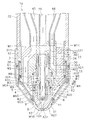
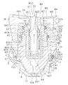
以下、図面を参照して実施形態に係るプラズマトーチについて説明する。図1は、第1実施形態に係るプラズマトーチ1aの中心軸線に沿った断面図である。図2は、プラズマトーチ1aの分解図である。本実施形態においてプラズマトーチ1aは、酸素プラズマ切断用のプラズマトーチ1aである。ただし、プラズマトーチ1aは、窒素やアルゴンなど酸素を含まないガスを用いるプラズマ切断用のプラズマトーチであってもよい。
1. First Embodiment 1.1 Configuration of Plasma Torch Hereinafter, a plasma torch according to an embodiment will be described with reference to the drawings. FIG. 1 is a cross-sectional view along the central axis of the plasma torch 1a according to the first embodiment. FIG. 2 is an exploded view of the plasma torch 1a. In the present embodiment, the plasma torch 1a is a plasma torch 1a for oxygen plasma cutting. However, the plasma torch 1a may be a plasma torch for plasma cutting using a gas containing no oxygen, such as nitrogen or argon.

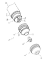
図2に示すように、プラズマトーチ1aは、交換部品ユニット2aと、トーチ本体3と、第1リテーナキャップ4と、第2リテーナキャップ5とを有する。交換部品ユニット2aと、第1リテーナキャップ4と、第2リテーナキャップ5とは、トーチ本体3の中心軸線と同心に配置される。   As shown in FIG. 2, the plasma torch 1 a has a replacement part unit 2 a, a torch main body 3, a first retainer cap 4 and a second retainer cap 5. The replacement part unit 2 a, the first retainer cap 4 and the second retainer cap 5 are disposed concentrically with the central axis of the torch body 3.

図1に示すように、交換部品ユニット2aは、トーチ本体3に取り付けられる。交換部品ユニット2aは、電極6と、絶縁ガイド7と、ノズル8と、絶縁リング9と、シールドキャップ10とを有する。交換部品ユニット2aについては後に詳細に説明する。   As shown in FIG. 1, the replacement part unit 2 a is attached to the torch body 3. The replacement part unit 2 a includes an electrode 6, an insulation guide 7, a nozzle 8, an insulation ring 9, and a shield cap 10. The replacement part unit 2a will be described in detail later.

トーチ本体3は、固定リング31を介して接続管32に取り付けられている。トーチ本体3は、ベース部33と、電極台座34と、センタパイプ20と、ノズル台座36と、絶縁スリーブ37と、ホルダ38とを有する。ベース部33と、電極台座34と、センタパイプ20と、ノズル台座36と、絶縁スリーブ37と、ホルダ38とは、トーチ本体3の中心軸線と同心に配置される。   The torch body 3 is attached to the connection pipe 32 via a fixing ring 31. The torch main body 3 has a base portion 33, an electrode pedestal 34, a center pipe 20, a nozzle pedestal 36, an insulating sleeve 37, and a holder 38. The base portion 33, the electrode pedestal 34, the center pipe 20, the nozzle pedestal 36, the insulating sleeve 37, and the holder 38 are disposed concentrically with the central axis of the torch body 3.

ベース部33は、円筒状の形状を有する。ベース部33は、導電体で形成されている。センタパイプ20と電極台座34と絶縁スリーブ37とは、ベース部33の孔に挿入されている。電極台座34は、円管状の形状を有する。電極台座34は、導電体で形成されている。ベース部33は、図示しない電源からのケーブルと電気的に接続されている。   The base portion 33 has a cylindrical shape. The base portion 33 is formed of a conductor. The center pipe 20, the electrode pedestal 34 and the insulating sleeve 37 are inserted into the holes of the base portion 33. The electrode pedestal 34 has a circular tubular shape. The electrode pedestal 34 is formed of a conductor. The base portion 33 is electrically connected to a cable from a power supply (not shown).

センタパイプ20は、電極台座34の孔に挿入されている。センタパイプ20は、管状の形状を有する。センタパイプ20は、導電体で形成されている。センタパイプ20の先端は、ノズル台座36の先端から突出している。センタパイプ20については後に詳細に説明する。   The center pipe 20 is inserted into the hole of the electrode pedestal 34. The center pipe 20 has a tubular shape. The center pipe 20 is formed of a conductor. The tip of the center pipe 20 projects from the tip of the nozzle pedestal 36. The center pipe 20 will be described in detail later.

絶縁スリーブ37は、円管状の形状を有する。絶縁スリーブ37は、絶縁体で形成されている。絶縁スリーブ37の一部は、ベース部33の孔内に配置されている。絶縁スリーブ37は、電極台座34とノズル台座36との間に位置している。   The insulating sleeve 37 has a circular tubular shape. The insulating sleeve 37 is formed of an insulator. A portion of the insulating sleeve 37 is disposed in the hole of the base portion 33. The insulating sleeve 37 is located between the electrode pedestal 34 and the nozzle pedestal 36.

ノズル台座36は、円管状の形状を有する。ノズル台座36の先端部は、先細り形状を有する。ノズル台座36は、絶縁体で形成されている。ノズル台座36には、ノズルに電気的に接触する接触子(図示せず)が取り付けられている。接触子は、電源からのケーブルと電気的に接続されている。ベース部33は、ノズル台座36の孔に挿入されている。絶縁スリーブ37は、ノズル台座36の孔に挿入されている。絶縁スリーブ37の先端部は、ベース部33から突出しており、ノズル台座36の孔内に配置されている。   The nozzle pedestal 36 has a circular tubular shape. The tip of the nozzle pedestal 36 has a tapered shape. The nozzle pedestal 36 is formed of an insulator. The nozzle pedestal 36 is attached with a contact (not shown) that electrically contacts the nozzle. The contacts are electrically connected to the cable from the power supply. The base portion 33 is inserted into the hole of the nozzle pedestal 36. The insulating sleeve 37 is inserted into the hole of the nozzle pedestal 36. The tip of the insulating sleeve 37 projects from the base 33 and is disposed in the hole of the nozzle pedestal 36.

ホルダ38は、円管状の形状を有する。ホルダ38は、接着等の手段により接続管32に取り付けられている。ノズル台座36は、ホルダ38の孔に挿入されている。ノズル台座36の先端部は、ホルダ38から突出している。   The holder 38 has a circular tubular shape. The holder 38 is attached to the connection pipe 32 by means such as adhesion. The nozzle pedestal 36 is inserted into the hole of the holder 38. The tip of the nozzle pedestal 36 protrudes from the holder 38.

第1リテーナキャップ4は、先端部が先細りした円筒状の形状を有する。第1リテーナキャップ4は、ノズル台座36を覆うように、トーチ本体3に取り付けられる。第1リテーナキャップ4の先端部は、シールドキャップ10が挿入される開口41を有する。ホルダ38とノズル台座36とは、第1リテーナキャップ4内に配置される。ホルダ38の外周面には、雄ネジ部311が設けられている。第1リテーナキャップ4の基端部の内周面には、雌ネジ部42が設けられている。ホルダ38の雄ネジ部311が第1リテーナキャップ4の雌ネジ部42に螺合することで、第1リテーナキャップ4がトーチ本体3に取り付けられる。   The first retainer cap 4 has a cylindrical shape with a tapered tip. The first retainer cap 4 is attached to the torch body 3 so as to cover the nozzle pedestal 36. The tip of the first retainer cap 4 has an opening 41 into which the shield cap 10 is inserted. The holder 38 and the nozzle pedestal 36 are disposed in the first retainer cap 4. A male screw portion 311 is provided on the outer peripheral surface of the holder 38. A female screw portion 42 is provided on the inner peripheral surface of the proximal end portion of the first retainer cap 4. The first retainer cap 4 is attached to the torch body 3 by screwing the male screw portion 311 of the holder 38 with the female screw portion 42 of the first retainer cap 4.

第2リテーナキャップ5は、先端部が先細りした円筒状の形状を有する。第2リテーナキャップ5の先端部は、シールドキャップ10が挿入される開口51を有する。第2リテーナキャップ5は、第1リテーナキャップ4を覆うように、第1リテーナキャップ4に取り付けられる。第1リテーナキャップ4は、第2リテーナキャップ5内に配置される。第1リテーナキャップ4と第2リテーナキャップ5とは、交換部品ユニット2aを保持すると共に挟み込む。第1リテーナキャップ4の外周面にはOリングR1が配置されている。第1リテーナキャップ4の外周面には雄ネジ401が設けられており、第2リテーナキャップ5の内周面には、雌ネジ501が設けられている。第1リテーナキャップ4の雄ネジ401と第2リテーナキャップ5の雌ネジ501とが螺合することで、第2リテーナキャップ5が第1リテーナキャップ4に取り付けられる。   The second retainer cap 5 has a cylindrical shape whose tip end is tapered. The tip of the second retainer cap 5 has an opening 51 into which the shield cap 10 is inserted. The second retainer cap 5 is attached to the first retainer cap 4 so as to cover the first retainer cap 4. The first retainer cap 4 is disposed in the second retainer cap 5. The first retainer cap 4 and the second retainer cap 5 hold and sandwich the replacement part unit 2a. An O-ring R1 is disposed on the outer peripheral surface of the first retainer cap 4. An external thread 401 is provided on the outer peripheral surface of the first retainer cap 4, and an internal thread 501 is provided on the inner peripheral surface of the second retainer cap 5. The second retainer cap 5 is attached to the first retainer cap 4 by screwing the male screw 401 of the first retainer cap 4 and the female screw 501 of the second retainer cap 5 with each other.

1.2 交換部品ユニットの構成
次に交換部品ユニット2aについて説明する。図3は、交換部品ユニット2aの側面図である。図4は、交換部品ユニット2aの中心軸線に沿った断面図である。
1.2 Configuration of Replacement Parts Unit Next, the replacement parts unit 2a will be described. FIG. 3 is a side view of the replacement part unit 2a. FIG. 4 is a cross-sectional view along the central axis of the replacement part unit 2a.

図3及び図4に示すように、交換部品ユニット2aは、電極6と絶縁ガイド7とノズル8と絶縁リング9とシールドキャップ10とが圧入により一体化されたものである。電極6と絶縁ガイド7とノズル8と絶縁リング9とシールドキャップ10とは、互いに同心に配置される。なお、交換部品ユニット2aはトーチ本体3の中心軸線と同心に配置されるため、電極6と絶縁ガイド7とノズル8と絶縁リング9とシールドキャップ10とのそれぞれの軸線とは、トーチ本体3の中心軸線と一致する。   As shown in FIGS. 3 and 4, the replacement part unit 2a is an integrated assembly of the electrode 6, the insulating guide 7, the nozzle 8, the insulating ring 9, and the shield cap 10 by press fitting. The electrode 6, the insulating guide 7, the nozzle 8, the insulating ring 9 and the shield cap 10 are arranged concentrically with each other. Since the replacement parts unit 2 a is disposed concentrically with the central axis of the torch main body 3, the axes of the electrode 6, the insulating guide 7, the nozzle 8, the insulating ring 9 and the shield cap 10 are the same as those of the torch main body 3. It coincides with the central axis.

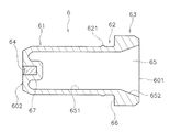
図5及び図6は、電極6の斜視図である。図7は電極6の断面図である。図5から図6に示すように、電極6は円筒状の形状を有している。電極6は、導電体で形成されている。電極6は、電極本体部61と、接合部62と、フランジ部63とを有している。   5 and 6 are perspective views of the electrode 6. FIG. 7 is a cross-sectional view of the electrode 6. As shown in FIGS. 5 to 6, the electrode 6 has a cylindrical shape. The electrode 6 is formed of a conductor. The electrode 6 has an electrode body 61, a joint 62, and a flange 63.

電極本体部61は、電極6の先端を含む。電極6の先端面602の中央には、耐熱インサート64が埋め込まれている。本実施形態において、耐熱インサート64は、例えばハフニウム製である。ただし、ハフニウム以外の電極材料が耐熱インサート64として用いられてもよい。図4に示すように、電極本体部61の一部は、絶縁ガイド7の孔内に配置されている。電極本体部61の先端部は、絶縁ガイド7から突出している。電極本体部61の先端部は先細りの形状を有する。   The electrode body 61 includes the tip of the electrode 6. A heat resistant insert 64 is embedded in the center of the tip end surface 602 of the electrode 6. In the present embodiment, the heat-resistant insert 64 is made of, for example, hafnium. However, an electrode material other than hafnium may be used as the heat-resistant insert 64. As shown in FIG. 4, a part of the electrode main portion 61 is disposed in the hole of the insulating guide 7. The tip of the electrode body 61 projects from the insulating guide 7. The tip of the electrode body 61 has a tapered shape.

接合部62は、電極本体部61の基端側に位置している。接合部62は、電極6の軸線方向において電極本体部61とフランジ部63との間に位置する。接合部62は、圧入によって絶縁ガイド7と接合される。従って、接合部62は、Oリング無しで流体をシールするように絶縁ガイド7と接合される。   The bonding portion 62 is located on the proximal end side of the electrode main portion 61. The joint portion 62 is located between the electrode body portion 61 and the flange portion 63 in the axial direction of the electrode 6. The joint portion 62 is joined to the insulating guide 7 by press fitting. Thus, the joint 62 is joined with the insulating guide 7 to seal the fluid without the O-ring.

接合部62の外周面は、絶縁ガイド7の内周面に係止する凹凸形状を有している。詳細には、接合部62は、凸部621を有する。凸部621は、接合部62の外周面から突出している。凸部621は、接合部62の周方向に延びている。   The outer peripheral surface of the joint portion 62 has an uneven shape that is engaged with the inner peripheral surface of the insulating guide 7. Specifically, the joint portion 62 has a convex portion 621. The convex portion 621 protrudes from the outer peripheral surface of the joint portion 62. The convex portion 621 extends in the circumferential direction of the joint portion 62.

フランジ部63は、接合部62の基端側に位置している。フランジ部63は、電極6の基端を含む。フランジ部63は、接合部62よりも大きな外径を有する。フランジ部63は、電極6の軸線方向において、接合部62よりも長い。フランジ部63の外周面は、電極6の軸線方向に延びている。フランジ部63の外周面は、断面視において凹凸の無い平坦な形状を有する。フランジ部63の外周面の基端部には面取りが施されている。フランジ部63と接合部62との間には、段部66が設けられている。段部66は、電極6の軸線方向に垂直な面である。   The flange portion 63 is located on the proximal end side of the joint portion 62. The flange portion 63 includes the proximal end of the electrode 6. The flange portion 63 has an outer diameter larger than that of the joint portion 62. The flange portion 63 is longer than the joint portion 62 in the axial direction of the electrode 6. The outer peripheral surface of the flange portion 63 extends in the axial direction of the electrode 6. The outer peripheral surface of the flange portion 63 has a flat shape without unevenness in cross sectional view. The base end portion of the outer peripheral surface of the flange portion 63 is chamfered. A step 66 is provided between the flange 63 and the joint 62. The step 66 is a surface perpendicular to the axial direction of the electrode 6.

電極6は、内部通路65を有する。内部通路65には、図1に示すセンタパイプ20が挿入される。電極6の基端面601には、内部通路65の入口が設けられている。内部通路65は、電極6の基端面601から先端へ向かって電極6の軸線方向に沿って延びている。電極6の先端の内部通路65側には、凸部67が設けられている。上述した耐熱インサート64は、凸部67内に配置される。交換部品ユニット2aがトーチ本体3に取り付けられた状態で、凸部67の一部は、センタパイプ20の冷却水路内に配置される。   The electrode 6 has an internal passage 65. The center pipe 20 shown in FIG. 1 is inserted into the internal passage 65. The proximal end face 601 of the electrode 6 is provided with the inlet of the internal passage 65. The inner passage 65 extends along the axial direction of the electrode 6 from the proximal end face 601 of the electrode 6 toward the tip. A protrusion 67 is provided on the inner passage 65 side of the tip of the electrode 6. The heat resistant insert 64 described above is disposed in the projection 67. A part of the convex portion 67 is disposed in the cooling water channel of the center pipe 20 in a state where the replacement part unit 2a is attached to the torch main body 3.

内部通路65の内周面は、直線部651とテーパ部652とを有する。直線部651は、電極6の軸線方向に平行に延びている。テーパ部652は、内部通路65の入口に向かって径方向に拡大している。   The inner circumferential surface of the inner passage 65 has a straight portion 651 and a tapered portion 652. The straight portion 651 extends in parallel with the axial direction of the electrode 6. The tapered portion 652 radially expands toward the inlet of the internal passage 65.

次に絶縁ガイド7について説明する。図8及び図9は、絶縁ガイド7の斜視図である。図10は、絶縁ガイド7の断面図である。絶縁ガイド7は、電極6とノズル8とを電気的に絶縁すると共に、電極6とノズル8とを連結する。絶縁ガイド7は、電極6とノズル8とを、軸線方向及び径方向に、互いに位置決めする。   Next, the insulation guide 7 will be described. 8 and 9 are perspective views of the insulating guide 7. FIG. 10 is a cross-sectional view of the insulating guide 7. The insulating guide 7 electrically insulates the electrode 6 from the nozzle 8 and connects the electrode 6 to the nozzle 8. The insulating guide 7 positions the electrode 6 and the nozzle 8 mutually in the axial direction and in the radial direction.

絶縁ガイド7は、管状の形状を有する。絶縁ガイド7は、絶縁体で形成されている。絶縁ガイド7は、電極6が挿入される孔706を有する。絶縁ガイド7の孔706は、絶縁ガイド7の軸線方向に絶縁ガイド7を貫通している。   The insulating guide 7 has a tubular shape. The insulating guide 7 is formed of an insulator. The insulating guide 7 has a hole 706 into which the electrode 6 is inserted. The hole 706 of the insulating guide 7 penetrates the insulating guide 7 in the axial direction of the insulating guide 7.

絶縁ガイド7は、セラミックの弾性率よりも小さな弾性率を有する材料で形成される。本実施形態において、絶縁ガイド7は、エンジニアプラスティック等の樹脂製である。詳細には、絶縁ガイド7は、連続使用温度が100℃以上の樹脂製である。さらに、連続使用温度が300℃以下であることが好ましい。ただし、絶縁ガイド7は樹脂以外の材料で形成されてもよい。   The insulating guide 7 is formed of a material having a smaller elastic modulus than that of ceramic. In the present embodiment, the insulation guide 7 is made of resin such as engineer plastic. In detail, the insulation guide 7 is made of resin whose continuous use temperature is 100 ° C. or more. Furthermore, it is preferable that continuous use temperature is 300 degrees C or less. However, the insulating guide 7 may be formed of a material other than resin.

図10に示すように、絶縁ガイド7の内周面は、第1内周面71と内側段部72と第2内周面73とを有する。第1内周面71は、絶縁ガイド7の軸線方向に延びており、絶縁ガイド7の先端面701に到達している。第1内周面71は、第2内周面73よりも大きな内径を有する。第1内周面71は、電極本体部61の外周面に対して隙間を隔てて対向する。後述するように、第1内周面71は、電極本体部61の外周面との間にガス通路を構成する。第1内周面71の内径は、ノズル8の内径と略同じである。従って、第1内周面71と電極6との間のガス通路の内径は、ノズル8の内径と略同じである。   As shown in FIG. 10, the inner circumferential surface of the insulating guide 7 has a first inner circumferential surface 71, an inner step portion 72, and a second inner circumferential surface 73. The first inner circumferential surface 71 extends in the axial direction of the insulating guide 7 and reaches the tip surface 701 of the insulating guide 7. The first inner circumferential surface 71 has an inner diameter larger than that of the second inner circumferential surface 73. The first inner circumferential surface 71 faces the outer circumferential surface of the electrode main body 61 with a gap. As described later, the first inner circumferential surface 71 constitutes a gas passage between the first inner circumferential surface 71 and the outer circumferential surface of the electrode main body 61. The inner diameter of the first inner circumferential surface 71 is substantially the same as the inner diameter of the nozzle 8. Accordingly, the inner diameter of the gas passage between the first inner circumferential surface 71 and the electrode 6 is substantially the same as the inner diameter of the nozzle 8.

内側段部72は、第1内周面71の基端側に位置する。内側段部72は、絶縁ガイド7の軸線方向において第1内周面71と第2内周面73との間に位置する。内側段部72は、先端側へ向かって径方向に拡大するように、絶縁ガイド7の軸線方向に対して傾斜している。   The inner step portion 72 is located on the proximal end side of the first inner circumferential surface 71. The inner step portion 72 is located between the first inner circumferential surface 71 and the second inner circumferential surface 73 in the axial direction of the insulating guide 7. The inner step portion 72 is inclined with respect to the axial direction of the insulating guide 7 so as to radially expand toward the tip end side.

第1内周面71と内側段部72とには、耐熱被膜707が形成されている。耐熱被膜707は、セラミック系材料で形成されている。耐熱被膜707は、例えば、窒化ホウ素で形成される。ただし、耐熱被膜707は、窒化ホウ素以外のセラミック系材料で形成されてもよい。或いは、耐熱被膜707は、セラミック系材料以外の耐熱性材料で形成されてもよい。或いは、耐熱被膜707は省略されてもよい。   A heat resistant film 707 is formed on the first inner circumferential surface 71 and the inner step portion 72. The heat-resistant film 707 is formed of a ceramic material. The heat-resistant film 707 is formed of, for example, boron nitride. However, the heat-resistant film 707 may be formed of a ceramic material other than boron nitride. Alternatively, the heat-resistant film 707 may be formed of a heat-resistant material other than the ceramic material. Alternatively, the heat resistant film 707 may be omitted.

第2内周面73は、内側段部72の基端側に位置する。第2内周面73は、絶縁ガイド7の軸線方向に延びており、絶縁ガイド7の基端面702に到達している。第2内周面73は、第1接合部74を有する。第1接合部74は、電極6の接合部62に圧入により接合される。従って、絶縁ガイド7の第1接合部74は、Oリング無しで流体をシールするように電極6と接合される。   The second inner circumferential surface 73 is located on the proximal end side of the inner step portion 72. The second inner circumferential surface 73 extends in the axial direction of the insulating guide 7 and reaches the proximal end surface 702 of the insulating guide 7. The second inner circumferential surface 73 has a first joint portion 74. The first bonding portion 74 is bonded to the bonding portion 62 of the electrode 6 by press-fitting. Thus, the first joint 74 of the insulating guide 7 is joined with the electrode 6 to seal the fluid without the O-ring.

図4に示すように、絶縁ガイド7の第1接合部74が電極6の接合部62に接合されることにより、電極6と絶縁ガイド7とが径方向に互いに位置決めされる。また、絶縁ガイド7の基端面702が、電極6のフランジ部63の段部66に接触することで、電極6と絶縁ガイド7とが軸線方向に互いに位置決めされる。   As shown in FIG. 4, by bonding the first bonding portion 74 of the insulating guide 7 to the bonding portion 62 of the electrode 6, the electrode 6 and the insulating guide 7 are positioned relative to each other in the radial direction. Further, when the base end surface 702 of the insulating guide 7 contacts the step 66 of the flange 63 of the electrode 6, the electrode 6 and the insulating guide 7 are positioned relative to each other in the axial direction.

第1接合部74は、電極6の外周面に係止する凹凸形状を有する。詳細には、第1接合部74は、凸部741を有する。凸部741は、第2内周面73から突出している。凸部741は、第2内周面73の周方向に延びている。絶縁ガイド7の第1接合部74の凸部741は、電極6の接合部62の凸部621に係止する。これにより、絶縁ガイド7が電極6に対して強固に抜け止めされる。   The first bonding portion 74 has a concavo-convex shape that is locked to the outer peripheral surface of the electrode 6. Specifically, the first joint portion 74 has a convex portion 741. The convex portion 741 protrudes from the second inner circumferential surface 73. The convex portion 741 extends in the circumferential direction of the second inner circumferential surface 73. The convex portion 741 of the first joint portion 74 of the insulating guide 7 is engaged with the convex portion 621 of the joint portion 62 of the electrode 6. As a result, the insulating guide 7 is firmly held off the electrode 6.

絶縁ガイド7の外周面は、第1外周面75と、第2外周面76と、第3外周面77とを有する。第1外周面75は、絶縁ガイド7の軸線方向に延びており、絶縁ガイド7の先端面701に到達している。第1外周面75は、ノズル8の第1孔811内に配置される。第1外周面75は、第2接合部78を有する。第2接合部78は、ノズル8の内周面に圧入により接合される。従って、絶縁ガイド7の第2接合部78は、Oリング無しで流体をシールするようにノズル8と接合される。   The outer peripheral surface of the insulating guide 7 has a first outer peripheral surface 75, a second outer peripheral surface 76, and a third outer peripheral surface 77. The first outer circumferential surface 75 extends in the axial direction of the insulating guide 7 and reaches the tip surface 701 of the insulating guide 7. The first outer circumferential surface 75 is disposed in the first hole 811 of the nozzle 8. The first outer circumferential surface 75 has a second joint 78. The second bonding portion 78 is bonded to the inner peripheral surface of the nozzle 8 by press-fitting. Thus, the second joint 78 of the insulating guide 7 is joined with the nozzle 8 to seal the fluid without an O-ring.

絶縁ガイド7の第2接合部78は、ノズル8の内周面に係止する凹凸形状を有する。詳細には、絶縁ガイド7の第2接合部78は、凸部781を有する。凸部781は、第1外周面75から突出している。凸部781は、第1外周面75の周方向に延びている。   The second bonding portion 78 of the insulating guide 7 has a concavo-convex shape that is engaged with the inner peripheral surface of the nozzle 8. In detail, the second joint portion 78 of the insulating guide 7 has a convex portion 781. The convex portion 781 protrudes from the first outer circumferential surface 75. The convex portion 781 extends in the circumferential direction of the first outer circumferential surface 75.

第2外周面76は、第1外周面75の基端側に位置する。第2外周面76は、絶縁ガイド7の軸線方向に延びている。第2外周面76は、断面視において、凹凸の無い平坦な形状を有する。第2外周面76は、絶縁ガイド7の軸線方向において第1外周面75と第3外周面77との間に配置される。第2外周面76は、ノズル8の外部に配置される。第2外周面76は、第1外周面75よりも小さな外径を有する。言い換えれば、第1外周面75の外径は、第2外周面76の外径よりも大きい。絶縁ガイド7の軸線方向において、第1外周面75は、第2外周面76よりも短い。   The second outer circumferential surface 76 is located on the proximal end side of the first outer circumferential surface 75. The second outer circumferential surface 76 extends in the axial direction of the insulating guide 7. The second outer peripheral surface 76 has a flat shape without unevenness in a cross sectional view. The second outer circumferential surface 76 is disposed between the first outer circumferential surface 75 and the third outer circumferential surface 77 in the axial direction of the insulating guide 7. The second outer circumferential surface 76 is disposed outside the nozzle 8. The second outer circumferential surface 76 has an outer diameter smaller than that of the first outer circumferential surface 75. In other words, the outer diameter of the first outer circumferential surface 75 is larger than the outer diameter of the second outer circumferential surface 76. In the axial direction of the insulating guide 7, the first outer circumferential surface 75 is shorter than the second outer circumferential surface 76.

第3外周面77は、第2外周面76の基端側に位置する。第3外周面77は、第2外周面76よりも小さな外径を有する。第3外周面77は、絶縁ガイド7の軸線方向に延びており、絶縁ガイド7の基端面702に到達している。絶縁ガイド7の軸線方向において、第2外周面76は、第3外周面77より長い。言い換えれば、絶縁ガイド7の軸線方向において、第3外周面77は、第2外周面76より短い。絶縁ガイド7の軸線方向において、第3外周面77は、第1外周面75より短い。   The third outer circumferential surface 77 is located on the proximal end side of the second outer circumferential surface 76. The third outer circumferential surface 77 has an outer diameter smaller than that of the second outer circumferential surface 76. The third outer peripheral surface 77 extends in the axial direction of the insulating guide 7 and reaches the proximal end surface 702 of the insulating guide 7. The second outer circumferential surface 76 is longer than the third outer circumferential surface 77 in the axial direction of the insulating guide 7. In other words, the third outer circumferential surface 77 is shorter than the second outer circumferential surface 76 in the axial direction of the insulating guide 7. The third outer circumferential surface 77 is shorter than the first outer circumferential surface 75 in the axial direction of the insulating guide 7.

絶縁ガイド7の外周面は、外側段部79を有する。外側段部79は、第2外周面76と第3外周面77との間に配置される。外側段部79は、絶縁ガイド7の軸線方向に垂直な面である。   The outer circumferential surface of the insulating guide 7 has an outer step 79. The outer step portion 79 is disposed between the second outer circumferential surface 76 and the third outer circumferential surface 77. The outer step portion 79 is a surface perpendicular to the axial direction of the insulating guide 7.

図11は、絶縁ガイド7を基端側から見た図である。図9及び図11に示すように、絶縁ガイド7は、複数の連通路703を有する。本実施形態では、絶縁ガイド7は6つの連通路703を有する。ただし、連通路703の数は、6つに限らず、6つより少ない、或いは6つより多くてもよい。   FIG. 11 is a view of the insulating guide 7 as viewed from the proximal side. As shown in FIGS. 9 and 11, the insulating guide 7 has a plurality of communication paths 703. In the present embodiment, the insulating guide 7 has six communicating passages 703. However, the number of communication paths 703 is not limited to six, and may be less than six or more than six.

図12は、1つの連通路703の軸線を含む絶縁ガイド7の断面を示している。図12に示すように、連通路703は、絶縁ガイド7の外部と絶縁ガイド7の孔706内とを連通している。言い換えると、連通路703は、絶縁ガイド7の外部と絶縁ガイド7内のガス通路とを連通している。連通路703は、軸線方向に対して傾斜した方向に延びている。連通路703は、絶縁ガイド7の先端へ向かって絶縁ガイド7の軸線に近づくように傾斜している。絶縁ガイド7の軸線方向に対する連通路703の傾斜角度は、30度以上、60度以下であることが好ましい。例えば、絶縁ガイド7の軸線方向に対する連通路703の傾斜角度は45度である。   FIG. 12 shows a cross section of the insulating guide 7 including the axis of one communication passage 703. As shown in FIG. 12, the communication passage 703 communicates the outside of the insulating guide 7 with the inside of the hole 706 of the insulating guide 7. In other words, the communication passage 703 communicates the outside of the insulating guide 7 with the gas passage in the insulating guide 7. The communication passage 703 extends in a direction inclined with respect to the axial direction. The communication path 703 is inclined so as to approach the axis of the insulating guide 7 toward the tip of the insulating guide 7. The inclination angle of the communication path 703 with respect to the axial direction of the insulating guide 7 is preferably 30 degrees or more and 60 degrees or less. For example, the inclination angle of the communication path 703 with respect to the axial direction of the insulating guide 7 is 45 degrees.

連通路703の一端は、内側段部72に接続される。連通路703の他端は、外側段部79に接続される。連通路703は、絶縁ガイド7の軸線方向における中心よりも基端側の位置において絶縁ガイド7の外周面に接続される、連通路703は、第1連通路704と第2連通路705とを有する。   One end of the communication passage 703 is connected to the inner step portion 72. The other end of the communication path 703 is connected to the outer step 79. The communication passage 703 is connected to the outer peripheral surface of the insulation guide 7 at a position closer to the base end than the center in the axial direction of the insulation guide 7. The communication passage 703 includes the first communication passage 704 and the second communication passage 705. Have.

第1連通路704は、第2連通路705よりも大きな流路断面を有する。第1連通路704は、外側段部79に接続される。第1連通路704は、絶縁ガイド7の外部に連通する。第2連通路705は、内側段部72に接続される。第2連通路705は、絶縁ガイド7内のガス通路に連通する。なお、図12では1つの連通路703のみが図示されているが、他の連通路703も図12の連通路703と同様の構造である。   The first communication passage 704 has a flow passage cross section larger than that of the second communication passage 705. The first communication passage 704 is connected to the outer step 79. The first communication passage 704 communicates with the outside of the insulating guide 7. The second communication passage 705 is connected to the inner step portion 72. The second communication passage 705 communicates with the gas passage in the insulating guide 7. Although only one communication passage 703 is illustrated in FIG. 12, the other communication passages 703 have the same structure as the communication passage 703 in FIG. 12.

図11に示すように、複数の連通路703は、周方向及び径方向に対して傾斜している。全ての連通路703は、周方向に対して同方向に傾斜している。全ての連通路703は、径方向に対して同方向に傾斜している。これにより、連通路703から吹き出されたガスは旋回流となる。複数の連通路703は、絶縁ガイド7の周方向において等間隔に配置される。絶縁ガイド7の軸線方向から見て、連通路703の軸線は、連通路703の軸線と平行であり且つ絶縁ガイド7の中心を通る直線から所定距離、離れている。   As shown in FIG. 11, the plurality of communication paths 703 are inclined with respect to the circumferential direction and the radial direction. All the communication paths 703 are inclined in the same direction with respect to the circumferential direction. All the communication paths 703 are inclined in the same direction with respect to the radial direction. Thus, the gas blown out from the communication passage 703 becomes a swirling flow. The plurality of communication paths 703 are arranged at equal intervals in the circumferential direction of the insulating guide 7. When viewed in the axial direction of the insulating guide 7, the axis of the communication passage 703 is separated from a straight line parallel to the axis of the communication passage 703 and passing through the center of the insulating guide 7.

次にノズル8について説明する。図13及び図14は、ノズル8の斜視図である。図15は、ノズル8の断面図である。ノズル8は、先端部が先細り形状を有する円筒状の形状を有する。ノズル8は、絶縁ガイド7が挿入される孔811を有し、絶縁ガイド7と圧入により接合される。詳細には、ノズル8は、第1ノズル部81と第2ノズル部82と第3ノズル部83とを有する。   Next, the nozzle 8 will be described. 13 and 14 are perspective views of the nozzle 8. FIG. 15 is a cross-sectional view of the nozzle 8. The nozzle 8 has a cylindrical shape whose tip has a tapered shape. The nozzle 8 has a hole 811 into which the insulating guide 7 is inserted, and is joined to the insulating guide 7 by press-fitting. Specifically, the nozzle 8 has a first nozzle portion 81, a second nozzle portion 82, and a third nozzle portion 83.

第1ノズル部81は、ノズル8の基端を含む。第1ノズル部81は、第1孔811を有する。第2ノズル部82は、第1ノズル部81の先端側に位置する。第2ノズル部82は、ノズル8の軸線方向において第1ノズル部81と第3ノズル部83との間に位置する。ノズル8の軸線方向において、第2ノズル部82は、第1ノズル部81よりも長い。   The first nozzle portion 81 includes the proximal end of the nozzle 8. The first nozzle portion 81 has a first hole 811. The second nozzle portion 82 is located on the tip side of the first nozzle portion 81. The second nozzle portion 82 is located between the first nozzle portion 81 and the third nozzle portion 83 in the axial direction of the nozzle 8. The second nozzle portion 82 is longer than the first nozzle portion 81 in the axial direction of the nozzle 8.

第2ノズル部82は、第1孔811に連通する第2孔821を有する。第2孔821は、第1孔811よりも小さな内径を有する。従って、第1ノズル部81の内周面812と第2ノズル部82の内周面822との間には内側段部84が設けられている。内側段部84は、ノズル8の軸線方向に垂直な面である。   The second nozzle portion 82 has a second hole 821 communicating with the first hole 811. The second hole 821 has an inner diameter smaller than that of the first hole 811. Therefore, an inner step portion 84 is provided between the inner circumferential surface 812 of the first nozzle portion 81 and the inner circumferential surface 822 of the second nozzle portion 82. The inner step portion 84 is a surface perpendicular to the axial direction of the nozzle 8.

第2ノズル部82の外径は、第1ノズル部81の外径と同じである。従って、第2ノズル部82の外周面823は、第1ノズル部81の外周面813と面一である。第1ノズル部81の外周面813の基端には面取りが施されている。第2ノズル部82は、第1ノズル部81よりも大きな径方向の厚さを有している。   The outer diameter of the second nozzle portion 82 is the same as the outer diameter of the first nozzle portion 81. Therefore, the outer peripheral surface 823 of the second nozzle portion 82 is flush with the outer peripheral surface 813 of the first nozzle portion 81. The base end of the outer peripheral surface 813 of the first nozzle portion 81 is chamfered. The second nozzle portion 82 has a radial thickness greater than that of the first nozzle portion 81.

第3ノズル部83は、ノズル8の先端を含む。第3ノズル部83は、第2ノズル部82の先端側に位置する。第3ノズル部83は、噴射孔831を有する。噴射孔831は、第2孔821よりも小さな内径を有する。噴射孔831は、ノズル8の軸線方向に延びており、ノズル8の先端面801に到達している。ノズル8の軸線方向において、上述した第1孔811は、噴射孔831よりも短い。   The third nozzle portion 83 includes the tip of the nozzle 8. The third nozzle portion 83 is located on the tip side of the second nozzle portion 82. The third nozzle portion 83 has an injection hole 831. The injection hole 831 has an inner diameter smaller than that of the second hole 821. The injection holes 831 extend in the axial direction of the nozzle 8 and reach the tip surface 801 of the nozzle 8. The first hole 811 described above is shorter than the injection hole 831 in the axial direction of the nozzle 8.

噴射孔831は、テーパ孔832を介して第2孔821に連通している。テーパ孔832は、ノズル8の軸線方向において噴射孔831と第2孔821との間に位置しており、噴射孔831と第2孔821とを接続している。テーパ孔832は、ノズル8の先端に向かって径方向に小さくなっている。   The injection hole 831 is in communication with the second hole 821 via the taper hole 832. The tapered hole 832 is located between the injection hole 831 and the second hole 821 in the axial direction of the nozzle 8 and connects the injection hole 831 and the second hole 821. The tapered hole 832 is reduced radially toward the tip of the nozzle 8.

ノズル8の外周面は、第1外周面85と第2外周面86と第3外周面87とを有する。第1外周面85は、ノズル8の基端面802に達している。第1外周面85は、第1ノズル部81の外周面813と第2ノズル部82の外周面823とによって構成される。第1外周面85は、断面視において、ノズル8の軸線方向に延びる直線状の形状を有する。言い換えれば、第1外周面85は、断面視において、凹凸の無い平坦な形状を有する。   The outer peripheral surface of the nozzle 8 has a first outer peripheral surface 85, a second outer peripheral surface 86, and a third outer peripheral surface 87. The first outer circumferential surface 85 reaches the proximal end surface 802 of the nozzle 8. The first outer circumferential surface 85 is formed by the outer circumferential surface 813 of the first nozzle portion 81 and the outer circumferential surface 823 of the second nozzle portion 82. The first outer peripheral surface 85 has a linear shape extending in the axial direction of the nozzle 8 in a cross sectional view. In other words, the first outer peripheral surface 85 has a flat shape without unevenness in cross sectional view.

第2外周面86は、第1外周面85の先端側に位置する。第2外周面86は、ノズル8の軸線方向において、第1外周面85と第3外周面87との間に位置する。第2外周面86は、第1外周面85よりも小さな外径を有する。従って、第1外周面85と第2外周面86との間には外側段部88が設けられている。外側段部88は、ノズル8の軸線方向に垂直な面である。   The second outer circumferential surface 86 is located on the tip side of the first outer circumferential surface 85. The second outer circumferential surface 86 is located between the first outer circumferential surface 85 and the third outer circumferential surface 87 in the axial direction of the nozzle 8. The second outer circumferential surface 86 has an outer diameter smaller than that of the first outer circumferential surface 85. Therefore, the outer side step portion 88 is provided between the first outer peripheral surface 85 and the second outer peripheral surface 86. The outer step portion 88 is a surface perpendicular to the axial direction of the nozzle 8.

第3外周面87は、第2外周面86の先端側に位置する。第3外周面87は、ノズル8の先端面801に到達している。第3外周面87は、先端に向かって径方向に小さくなるように傾斜している。   The third outer peripheral surface 87 is located on the tip side of the second outer peripheral surface 86. The third outer peripheral surface 87 reaches the tip end surface 801 of the nozzle 8. The third outer peripheral surface 87 is inclined to be smaller in the radial direction toward the tip.

第1ノズル部81の第1孔811には、絶縁ガイド7が挿入される。第2ノズル部82の第2孔821には、電極6が挿入される。図4に示すように、第2ノズル部82の内周面822は、隙間を隔てて電極本体部61と対向する。電極6の先端は、第3ノズル部83のテーパ孔832と対向している。   The insulating guide 7 is inserted into the first hole 811 of the first nozzle portion 81. The electrode 6 is inserted into the second hole 821 of the second nozzle portion 82. As shown in FIG. 4, the inner circumferential surface 822 of the second nozzle portion 82 faces the electrode main portion 61 with a gap. The tip of the electrode 6 faces the tapered hole 832 of the third nozzle portion 83.

第1ノズル部81は、絶縁ガイド7と接合される。詳細には、第1孔811に絶縁ガイド7の第2接合部78が挿入され、第1ノズル部81は、絶縁ガイド7の第2接合部78と圧入により接合される。これにより、第1ノズル部81の内周面812は、Oリング無しで流体をシールするように絶縁ガイド7と接合される。   The first nozzle portion 81 is joined to the insulating guide 7. Specifically, the second bonding portion 78 of the insulating guide 7 is inserted into the first hole 811, and the first nozzle portion 81 is press-bonded to the second bonding portion 78 of the insulating guide 7. Thereby, the inner circumferential surface 812 of the first nozzle portion 81 is joined to the insulating guide 7 so as to seal the fluid without the O-ring.

第1ノズル部81の内周面812が絶縁ガイド7の第2接合部78と接合することにより、ノズル8と絶縁ガイド7とが径方向に互いに位置決めされる。また、絶縁ガイド7の先端面701がノズル8の内側段部84に接触することにより、ノズル8と絶縁ガイド7とが軸線方向に互いに位置決めされる。   The inner circumferential surface 812 of the first nozzle portion 81 is joined to the second joint portion 78 of the insulating guide 7 to position the nozzle 8 and the insulating guide 7 in the radial direction. In addition, when the tip end surface 701 of the insulating guide 7 contacts the inner step portion 84 of the nozzle 8, the nozzle 8 and the insulating guide 7 are positioned relative to each other in the axial direction.

第1ノズル部81の内周面812は、絶縁ガイド7の外周面に係止する凹凸形状を有する。詳細には、第1ノズル部81の内周面812は、凸部814を有する。第1ノズル部81の凸部814は、絶縁ガイド7の第2接合部78の凸部781に係止する。これにより、ノズル8が絶縁ガイド7に対して抜け止めされる。   The inner circumferential surface 812 of the first nozzle portion 81 has an uneven shape that engages with the outer circumferential surface of the insulating guide 7. In detail, the inner circumferential surface 812 of the first nozzle portion 81 has a convex portion 814. The convex portion 814 of the first nozzle portion 81 is engaged with the convex portion 781 of the second joint portion 78 of the insulating guide 7. Thereby, the nozzle 8 is prevented from coming off with respect to the insulating guide 7.

第2外周面86は、絶縁リング9の内周面に係止する凹凸形状を有する。詳細には、第2外周面86は、凸部861を有する。   The second outer peripheral surface 86 has an uneven shape that engages with the inner peripheral surface of the insulating ring 9. In detail, the second outer circumferential surface 86 has a convex portion 861.

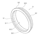
図16及び図17は、絶縁リング9の斜視図である。図18は、絶縁リング9の断面図である。図16から図18に示すように、絶縁リング9は、ノズル8が挿入される孔903を有する。絶縁リング9の内周面91は凸部911を有する。絶縁リング9の外周面92は凸部921を有する。   16 and 17 are perspective views of the insulating ring 9. FIG. 18 is a cross-sectional view of the insulating ring 9. As shown in FIGS. 16 to 18, the insulating ring 9 has a hole 903 into which the nozzle 8 is inserted. An inner circumferential surface 91 of the insulating ring 9 has a convex portion 911. An outer circumferential surface 92 of the insulating ring 9 has a convex portion 921.

絶縁リング9は、フランジ部93を有する。フランジ部93は、絶縁リング9の外周面92から突出している。従って、絶縁リング9の外周面92とフランジ部93との間には段部94が設けられている。段部94は、絶縁リング9の軸線方向に垂直な面である。   The insulating ring 9 has a flange portion 93. The flange portion 93 protrudes from the outer peripheral surface 92 of the insulating ring 9. Therefore, a step 94 is provided between the outer peripheral surface 92 of the insulating ring 9 and the flange 93. The stepped portion 94 is a surface perpendicular to the axial direction of the insulating ring 9.

図4に示すように、絶縁リング9は、ノズル8と圧入により接合される。詳細には、絶縁リング9の内周面91は、ノズル8の第2外周面86と圧入により接合される。絶縁リング9の内周面91がノズル8の第2外周面86と接合されることにより、絶縁リング9とノズル8とが径方向に互いに位置決めされる。   As shown in FIG. 4, the insulating ring 9 is joined to the nozzle 8 by press-fitting. Specifically, the inner circumferential surface 91 of the insulating ring 9 is joined to the second outer circumferential surface 86 of the nozzle 8 by press fitting. The inner circumferential surface 91 of the insulating ring 9 is joined to the second outer circumferential surface 86 of the nozzle 8 so that the insulating ring 9 and the nozzle 8 are positioned relative to each other in the radial direction.

また、絶縁リング9の基端面901がノズル8の外側端部88に接触することにより、絶縁リング9とノズル8とが軸線方向に互いに位置決めされる。絶縁リング9の内周面91の凸部911は、ノズル8の第2外周面86の凸部861に係止する。これにより、絶縁リング9がノズル8に対して強固に抜け止めされる。   Further, when the base end surface 901 of the insulating ring 9 contacts the outer end 88 of the nozzle 8, the insulating ring 9 and the nozzle 8 are positioned relative to each other in the axial direction. The convex portion 911 of the inner circumferential surface 91 of the insulating ring 9 is engaged with the convex portion 861 of the second outer circumferential surface 86 of the nozzle 8. As a result, the insulating ring 9 is firmly held off the nozzle 8.

図19及び図20は、シールドキャップ10の斜視図である。図21は、シールドキャップ10の断面図である。図19から図21に示すように、シールドキャップ10は孔103を有する。シールドキャップ10の孔103には、ノズル8が挿入される。シールドキャップ10は噴射孔104を有する。噴射孔104は、孔103と連通しており、シールドキャップ10の先端面101を軸線方向に貫通している。   19 and 20 are perspective views of the shield cap 10. FIG. 21 is a cross-sectional view of the shield cap 10. As shown in FIGS. 19 to 21, the shield cap 10 has a hole 103. The nozzle 8 is inserted into the hole 103 of the shield cap 10. The shield cap 10 has an injection hole 104. The injection hole 104 communicates with the hole 103, and penetrates the tip surface 101 of the shield cap 10 in the axial direction.

シールドキャップ10は、第1内周面11と第2内周面12とを有する。第1内周面11は、シールドキャップ10の軸線方向に延びており、シールドキャップ10の基端面102に到達している。第1内周面11は凸部111を有する。第2内周面12は、第1内周面11の先端側に位置する。第2内周面12は、先端に向かって径方向に小さくなるように傾斜している。   The shield cap 10 has a first inner circumferential surface 11 and a second inner circumferential surface 12. The first inner circumferential surface 11 extends in the axial direction of the shield cap 10 and reaches the proximal end surface 102 of the shield cap 10. The first inner circumferential surface 11 has a convex portion 111. The second inner circumferential surface 12 is located on the tip side of the first inner circumferential surface 11. The second inner circumferential surface 12 is inclined to be smaller in the radial direction toward the tip.

シールドキャップ10は、第1外周面13と、フランジ部14と、第2外周面15と、第3外周面16とを有する。第1外周面13は、シールドキャップ10の軸線方向に延びており、シールドキャップ10の基端面102に到達している。フランジ部14は、第1外周面13の先端側に位置する。フランジ部14は、シールドキャップ10の軸線方向において、第1外周面13と第2外周面15との間に位置する。フランジ部14は、第1外周面13から突出している。フランジ部14は、第2外周面15から突出している。フランジ部14と第2外周面15との間には、外側段部17が設けられている。外側段部17は、シールドキャップ10の軸線方向に垂直な面である。フランジ部14の外径は、第1リテーナキャップ4の開口41の直径よりも大きい。フランジ部14の外径は、第2リテーナキャップ5の開口51の直径よりも大きい。   The shield cap 10 has a first outer peripheral surface 13, a flange portion 14, a second outer peripheral surface 15, and a third outer peripheral surface 16. The first outer peripheral surface 13 extends in the axial direction of the shield cap 10 and reaches the proximal end surface 102 of the shield cap 10. The flange portion 14 is located on the tip side of the first outer circumferential surface 13. The flange portion 14 is located between the first outer peripheral surface 13 and the second outer peripheral surface 15 in the axial direction of the shield cap 10. The flange portion 14 protrudes from the first outer circumferential surface 13. The flange portion 14 protrudes from the second outer circumferential surface 15. An outer step 17 is provided between the flange 14 and the second outer circumferential surface 15. The outer step 17 is a surface perpendicular to the axial direction of the shield cap 10. The outer diameter of the flange portion 14 is larger than the diameter of the opening 41 of the first retainer cap 4. The outer diameter of the flange portion 14 is larger than the diameter of the opening 51 of the second retainer cap 5.

第2外周面15は、フランジ部14の先端側に位置する。第2外周面15は、第1外周面13よりも小さな外径を有する。第2外周面15は、シールドキャップ10の軸線方向に延びている。第3外周面16は、第2外周面15の先端側に位置する。第3外周面16は、シールドキャップ10の先端面101に到達している。第3外周面16は、先端に向かって径方向に小さくなるように、シールドキャップ10の軸線方向に対して傾斜している。   The second outer circumferential surface 15 is located on the tip side of the flange portion 14. The second outer circumferential surface 15 has an outer diameter smaller than that of the first outer circumferential surface 13. The second outer circumferential surface 15 extends in the axial direction of the shield cap 10. The third outer circumferential surface 16 is located on the tip side of the second outer circumferential surface 15. The third outer peripheral surface 16 reaches the tip end surface 101 of the shield cap 10. The third outer peripheral surface 16 is inclined with respect to the axial direction of the shield cap 10 so as to decrease in the radial direction toward the tip.

図22は、図21のA−A断面図である。図21及び図22に示すように、シールドキャップ10は、複数の連通路105を有する。連通路105は、シールドキャップ10の外部とシールドキャップ10の孔103内とを連通している。連通路105の一端は第1外周面13に到達している。連通路105の他端は、第1内周面11に到達している。   FIG. 22 is a cross-sectional view taken along line AA of FIG. As shown in FIGS. 21 and 22, the shield cap 10 has a plurality of communication paths 105. The communication passage 105 communicates the outside of the shield cap 10 with the inside of the hole 103 of the shield cap 10. One end of the communication passage 105 reaches the first outer peripheral surface 13. The other end of the communication passage 105 reaches the first inner circumferential surface 11.

連通路105は、シールドキャップ10の周方向に等間隔に配置されている。シールドキャップ10の軸線方向から見て、連通路105の軸線は、連通路105の軸線と平行であり且つ絶縁ガイド7の中心を通る直線から所定距離、離れている。全ての連通路105は、周方向に対して同方向に傾斜している。全ての連通路105は、径方向に対して同方向に傾斜している。これにより、連通路105から吹き出されたガスは旋回流となる。   The communication paths 105 are arranged at equal intervals in the circumferential direction of the shield cap 10. When viewed in the axial direction of the shield cap 10, the axis of the communication passage 105 is separated from a straight line which is parallel to the axis of the communication passage 105 and passes through the center of the insulating guide 7. All the communication paths 105 are inclined in the same direction with respect to the circumferential direction. All the communication paths 105 are inclined in the same direction with respect to the radial direction. Thus, the gas blown out from the communication passage 105 becomes a swirling flow.

図4に示すように、シールドキャップ10は、絶縁リング9と圧入により接合される。詳細には、シールドキャップ10の第1内周面11が、絶縁リング9の外周面92と圧入により接合される。シールドキャップ10の第1内周面11の凸部111は、絶縁リング9の外周面92の凸部921と係合する。これにより、シールドキャップ10が絶縁リング9に対して強固に抜け止めされる。   As shown in FIG. 4, the shield cap 10 is joined to the insulating ring 9 by press fitting. Specifically, the first inner circumferential surface 11 of the shield cap 10 is joined to the outer circumferential surface 92 of the insulating ring 9 by press fitting. The convex portion 111 of the first inner circumferential surface 11 of the shield cap 10 engages with the convex portion 921 of the outer circumferential surface 92 of the insulating ring 9. As a result, the shield cap 10 is firmly held off the insulating ring 9.

シールドキャップ10の第1内周面11が絶縁リング9の外周面92と接合されることにより、シールドキャップ10と絶縁リング9とが、径方向に互いに位置決めされる。これにより、シールドキャップ10の噴射孔104とノズル8の噴射孔831とが同心に配置される。   By bonding the first inner circumferential surface 11 of the shield cap 10 to the outer circumferential surface 92 of the insulating ring 9, the shield cap 10 and the insulating ring 9 are positioned relative to each other in the radial direction. As a result, the injection holes 104 of the shield cap 10 and the injection holes 831 of the nozzle 8 are arranged concentrically.

シールドキャップ10の基端面102が絶縁リング9の段部94に接触することにより、シールドキャップ10と絶縁リング9とが、軸線方向に互いに位置決めされる。これにより、シールドキャップ10がノズル8に対して隙間を隔てて配置される。詳細には、シールドキャップ10の第2内周面12が、ノズル8の第3外周面87に対して隙間を隔てて配置される。これにより、シールドキャップ10とノズル8との間には後述するガス通路が構成される。シールドキャップ10の連通路105は、絶縁リング9の先端よりも先端側に位置している。シールドキャップ10の連通路105は、シールドキャップ10とノズル8との間のガス通路に連通している。   When the base end face 102 of the shield cap 10 contacts the step 94 of the insulating ring 9, the shield cap 10 and the insulating ring 9 are positioned relative to each other in the axial direction. Thereby, the shield cap 10 is disposed at a gap from the nozzle 8. Specifically, the second inner circumferential surface 12 of the shield cap 10 is disposed with a gap from the third outer circumferential surface 87 of the nozzle 8. Thereby, a gas passage to be described later is formed between the shield cap 10 and the nozzle 8. The communication passage 105 of the shield cap 10 is located on the tip side of the tip of the insulating ring 9. The communication passage 105 of the shield cap 10 is in communication with the gas passage between the shield cap 10 and the nozzle 8.

次にセンタパイプ20について説明する。図23及び図24は、センタパイプ20の斜視図である。図25は、センタパイプ20の断面図である。センタパイプ20は、電極6の内部通路65に挿入され、電極6内に冷却水を供給する。センタパイプ20は、導電体で形成されている。センタパイプ20は、パイプ本体21と接触子22とを有する。図26は、パイプ本体21の斜視図である。図27は、接触子22の斜視図である。   Next, the center pipe 20 will be described. 23 and 24 are perspective views of the center pipe 20. FIG. FIG. 25 is a cross-sectional view of the center pipe 20. As shown in FIG. The center pipe 20 is inserted into the internal passage 65 of the electrode 6 to supply cooling water into the electrode 6. The center pipe 20 is formed of a conductor. The center pipe 20 has a pipe body 21 and a contact 22. FIG. 26 is a perspective view of the pipe body 21. FIG. FIG. 27 is a perspective view of the contact 22.

パイプ本体21は、管状の形状を有する。パイプ本体21は、導電体で形成される。詳細には、パイプ本体21の外周面は、フランジ部23と、第1外周面24と、第2外周面25と、第3外周面26とを有する。フランジ部23は、パイプ本体21の基端を含む。フランジ部23は、第1外周面24から突出している。従って、フランジ部23と第1外周面24との間には段部27が設けられている。段部27は、パイプ本体21の軸線方向に垂直な面である。   The pipe body 21 has a tubular shape. The pipe body 21 is formed of a conductor. Specifically, the outer peripheral surface of the pipe main body 21 has a flange portion 23, a first outer peripheral surface 24, a second outer peripheral surface 25, and a third outer peripheral surface 26. The flange portion 23 includes the proximal end of the pipe body 21. The flange portion 23 protrudes from the first outer peripheral surface 24. Therefore, a step 27 is provided between the flange 23 and the first outer peripheral surface 24. The stepped portion 27 is a surface perpendicular to the axial direction of the pipe body 21.

第1外周面24は、フランジ部23の先端側に位置する。第1外周面24は、パイプ本体21の軸線方向においてフランジ部23と第2外周面25との間に位置する。第1外周面24は、パイプ本体21の軸線方向に延びている。   The first outer peripheral surface 24 is located on the tip side of the flange portion 23. The first outer circumferential surface 24 is located between the flange portion 23 and the second outer circumferential surface 25 in the axial direction of the pipe body 21. The first outer circumferential surface 24 extends in the axial direction of the pipe body 21.

第2外周面25は、第1外周面24の先端側に位置する。第2外周面25は、パイプ本体21の軸線方向において第1外周面24と第3外周面26との間に位置する。第2外周面25は、パイプ本体21の軸線方向に延びている。パイプ本体21の軸線方向において、第2外周面25は、第1外周面24よりも短い。第2外周面25は、第1外周面24よりも小さな外径を有する。   The second outer circumferential surface 25 is located on the tip side of the first outer circumferential surface 24. The second outer circumferential surface 25 is located between the first outer circumferential surface 24 and the third outer circumferential surface 26 in the axial direction of the pipe body 21. The second outer circumferential surface 25 extends in the axial direction of the pipe body 21. The second outer peripheral surface 25 is shorter than the first outer peripheral surface 24 in the axial direction of the pipe main body 21. The second outer circumferential surface 25 has an outer diameter smaller than that of the first outer circumferential surface 24.

第3外周面26は、第2外周面25の先端側に位置する。第3外周面26は、パイプ本体21の先端を含む。第3外周面26は、パイプ本体21の軸線方向に延びている。パイプ本体21の軸線方向において第3外周面26は、第1外周面24よりも長い。第3外周面26は、第2外周面25よりも小さな外径を有する。第3外周面26の軸線方向における中間部には、凹部261が設けられている。凹部261には、接触子22が取り付けられる。   The third outer circumferential surface 26 is located on the tip side of the second outer circumferential surface 25. The third outer circumferential surface 26 includes the tip of the pipe body 21. The third outer circumferential surface 26 extends in the axial direction of the pipe body 21. The third outer circumferential surface 26 is longer than the first outer circumferential surface 24 in the axial direction of the pipe body 21. The third outer circumferential surface 26 has an outer diameter smaller than that of the second outer circumferential surface 25. A recess 261 is provided at an intermediate portion in the axial direction of the third outer peripheral surface 26. The contact 22 is attached to the recess 261.

パイプ本体21は、冷却水通路を内部に有する。冷却水通路は、パイプ本体21を軸線方向に貫通している。冷却水通路は、第1通路211と第2通路212と第3通路231とを有する。第1通路211は、パイプ本体21の基端面201に到達している。第1通路211は、先端に向かって径方向に小さくなるように、パイプ本体21の軸線方向に対して傾斜している。   The pipe body 21 has a cooling water passage inside. The cooling water passage penetrates the pipe body 21 in the axial direction. The cooling water passage has a first passage 211, a second passage 212 and a third passage 231. The first passage 211 reaches the proximal end face 201 of the pipe main body 21. The first passage 211 is inclined with respect to the axial direction of the pipe body 21 so as to decrease in the radial direction toward the tip.

第2通路212は、第1通路211の先端側に位置する。第2通路212は、パイプ本体21の軸線方向において、第1通路211と第3通路231との間に位置する。パイプ本体21の軸線方向において、第2通路212は、第3通路231よりも長い。第2通路212は、パイプ本体21の軸線方向に延びている。   The second passage 212 is located on the tip side of the first passage 211. The second passage 212 is located between the first passage 211 and the third passage 231 in the axial direction of the pipe body 21. The second passage 212 is longer than the third passage 231 in the axial direction of the pipe body 21. The second passage 212 extends in the axial direction of the pipe body 21.

第3通路231は、第2通路212の先端側に位置する。第3通路231は、パイプ本体21の先端面202に到達している。第3通路231は、第2通路212よりも大きな内径を有する。第3通路231内には、上述した電極6の凸部67が配置される。   The third passage 231 is located on the tip side of the second passage 212. The third passage 231 reaches the end surface 202 of the pipe body 21. The third passage 231 has an inner diameter larger than that of the second passage 212. The convex portion 67 of the electrode 6 described above is disposed in the third passage 231.

接触子22は、パイプ本体21と別体である。接触子22は導電体で形成される。接触子22は、パイプ本体21に対して着脱可能に取り付けられる。接触子22は、パイプ本体21の外周面に取り付けられる。詳細には、接触子22は、パイプ本体21の第3外周面26の凹部261に嵌め込まれることで、パイプ本体21に取り付けられる。   The contact 22 is separate from the pipe body 21. The contacts 22 are formed of a conductor. The contact 22 is detachably attached to the pipe body 21. The contact 22 is attached to the outer peripheral surface of the pipe body 21. In detail, the contactor 22 is attached to the pipe body 21 by being fitted into the recess 261 of the third outer peripheral surface 26 of the pipe body 21.

接触子22は、取付部28と接触部29とを有する。取付部28は、パイプ本体21の外周面に取り付けられる。取付部28は、第1環部281と第2環部282とを有する。第2環部282は、接触子22の軸線方向に第1環部281から離れて配置される。第1環部281と第2環部282とは、それぞれパイプ本体21の凹部261に嵌め込まれる。   The contact 22 has a mounting portion 28 and a contact portion 29. The attachment portion 28 is attached to the outer peripheral surface of the pipe body 21. The attachment portion 28 has a first ring portion 281 and a second ring portion 282. The second ring portion 282 is disposed apart from the first ring portion 281 in the axial direction of the contact 22. The first ring portion 281 and the second ring portion 282 are respectively fitted into the recess 261 of the pipe main body 21.

接触部29は、電極6の内周面に接触する。接触部29は、接触子22の径方向に押圧されることで反力を生じるように弾性を有する。具体的には、接触部29は、複数の湾曲部291を有する。湾曲部291は、第1環部281と第2環部282とを連結している。湾曲部291は、接触子22の径方向外方に向かって膨出した板状の形状を有する。接触部29は、複数のスリット292を有する。スリット292は、複数の湾曲部291の間に設けられ、接触子22の軸線方向に延びている。なお、図面においてはスリット292の一部のみに符号292を付して他のスリット292の符号を省略している。   The contact portion 29 contacts the inner circumferential surface of the electrode 6. The contact portion 29 has elasticity so as to generate a reaction force by being pressed in the radial direction of the contact 22. Specifically, the contact portion 29 has a plurality of curved portions 291. The curved portion 291 connects the first ring portion 281 and the second ring portion 282. The curved portion 291 has a plate-like shape bulging outward in the radial direction of the contact 22. The contact portion 29 has a plurality of slits 292. The slits 292 are provided between the plurality of curved portions 291 and extend in the axial direction of the contact 22. In the drawing, only a part of the slit 292 is given the reference numeral 292 and the reference numerals of the other slits 292 are omitted.

図28は、接触子22を軸線方向から見た図である。図28に示すように、複数の湾曲部291は、接触子22の周方向に等間隔に配置されている。複数のスリット292も同様に、接触子22の周方向に等間隔に配置されている。本実施形態では、接触子22は、8つの湾曲部291と8つのスリット292とを有している。しかし、接触子22の数は、8つに限らず、8つより少ない、或いは8つより多くてもよい。同様に、スリット292の数は、8つに限らず、8つより少ない、或いは8つより多くてもよい。   FIG. 28 is a view of the contact 22 as viewed from the axial direction. As shown in FIG. 28, the plurality of curved portions 291 are arranged at equal intervals in the circumferential direction of the contact 22. Similarly, the plurality of slits 292 are equally spaced in the circumferential direction of the contact 22. In the present embodiment, the contact 22 has eight curved portions 291 and eight slits 292. However, the number of contacts 22 is not limited to eight, and may be less than eight or more than eight. Similarly, the number of slits 292 is not limited to eight, and may be less than eight or more than eight.

図1に示すように、センタパイプ20のフランジ部23は、電極台座34の基端面341と、ベース部33の孔の底面331との間に配置される。フランジ部23は、電極台座34の基端面341に接触している。これにより、センタパイプ20と電極台座34とが電気的に接続されている。また、センタパイプ20が径方向及び軸線方向に位置決めされる。   As shown in FIG. 1, the flange portion 23 of the center pipe 20 is disposed between the base end surface 341 of the electrode pedestal 34 and the bottom surface 331 of the hole of the base portion 33. The flange portion 23 is in contact with the proximal end surface 341 of the electrode pedestal 34. Thus, the center pipe 20 and the electrode pedestal 34 are electrically connected. Further, the center pipe 20 is positioned in the radial direction and the axial direction.

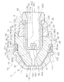
図29は、図1における交換部品ユニット2a及びその周囲の構成の拡大図である。図29に示すように、センタパイプ20の接触子22は、電極6の内周面に接触している。接触子22は、電極6の内部通路65に挿入されることで、径方向内方へ向かって弾性変形している。接触子22は、弾性変形の反力によって電極6の内周面に押し付けられている。センタパイプ20は、電極台座34と電気的に接続されている。従って、接触子22は、電極6の内周面に接触することで電極6に通電する。   FIG. 29 is an enlarged view of the replacement part unit 2a in FIG. 1 and the configuration around it. As shown in FIG. 29, the contact 22 of the center pipe 20 is in contact with the inner circumferential surface of the electrode 6. The contactor 22 is elastically deformed radially inward by being inserted into the inner passage 65 of the electrode 6. The contact 22 is pressed against the inner circumferential surface of the electrode 6 by the reaction force of the elastic deformation. The center pipe 20 is electrically connected to the electrode pedestal 34. Therefore, the contactor 22 contacts the inner peripheral surface of the electrode 6 to energize the electrode 6.

電極6は、第1通電面603と第2通電面601とを有する。第1通電面603は、内部通路65の内周面において接触子22と接触している部分である。電極6は、センタパイプ20と第1通電面603とを介して電極台座34と電気的に接続される。第1通電面603は、テーパ部652の先端側においてテーパ部652に隣接して配置される。第1通電面603は、後述する冷却水通路内に位置している。   The electrode 6 has a first conductive surface 603 and a second conductive surface 601. The first conductive surface 603 is a portion in contact with the contact 22 on the inner peripheral surface of the inner passage 65. The electrode 6 is electrically connected to the electrode pedestal 34 via the center pipe 20 and the first conduction surface 603. The first conductive surface 603 is disposed adjacent to the tapered portion 652 on the tip end side of the tapered portion 652. The first conductive surface 603 is located in a coolant passage described later.

第2通電面601は、電極6の基端面601である。第2通電面601は、電極台座34の先端面342に接触している。電極6は、第2通電面601を介して電極台座34と電気的に接続される。第2通電面601は、後述する冷却水通路に隣接している。   The second conductive surface 601 is a proximal end surface 601 of the electrode 6. The second conductive surface 601 is in contact with the front end surface 342 of the electrode pedestal 34. The electrode 6 is electrically connected to the electrode pedestal 34 via the second conduction surface 601. The second conductive surface 601 is adjacent to a cooling water passage described later.

1.3 冷却水通路
次に、プラズマトーチ1aの冷却水通路について説明する。図1において、実線の矢印は、冷却水の流れを示している。図1に示すように、ベース部33には、冷却水供給管45が接続されている。冷却水供給管45は、ベース部33内の第1冷却水通路W1を介して、ノズル台座36内の第2冷却水通路W2に接続されている。第1冷却水通路W1は、ベース部33の基端面からベース部33の外周面に向かって延びている。第2冷却水通路W2は、ノズル台座36の内周面からノズル台座36の先端部へ向かって延びている。第2冷却水通路W2は、第3冷却水通路W3に接続されている。第3冷却水通路W3は、ノズル台座36と第1リテーナキャップ4と交換部品ユニット2aとに囲まれた環状の通路である。
1.3 Cooling water passage Next, the cooling water passage of the plasma torch 1a will be described. In FIG. 1, solid arrows indicate the flow of cooling water. As shown in FIG. 1, a cooling water supply pipe 45 is connected to the base portion 33. The cooling water supply pipe 45 is connected to the second cooling water passage W2 in the nozzle pedestal 36 via the first cooling water passage W1 in the base portion 33. The first coolant passage W <b> 1 extends from the base end surface of the base portion 33 toward the outer peripheral surface of the base portion 33. The second coolant passage W <b> 2 extends from the inner circumferential surface of the nozzle pedestal 36 toward the tip of the nozzle pedestal 36. The second coolant passage W2 is connected to the third coolant passage W3. The third coolant passage W3 is an annular passage surrounded by the nozzle pedestal 36, the first retainer cap 4 and the replacement part unit 2a.

図29に示すように、絶縁スリーブ37の先端面371とノズル8の基端面802との間には隙間が設けられており、この隙間は、第3冷却水通路W3の一部を構成している。従って、ノズル8の基端面802は、第3冷却水通路W3内に配置される。また、絶縁スリーブ37の先端面371とノズル8の基端面802との隙間は、絶縁ガイド7の第2外周面76まで到達している。従って、絶縁ガイド7の第2外周面76の一部は、第3冷却水通路W3内に配置されている。   As shown in FIG. 29, a gap is provided between the front end surface 371 of the insulating sleeve 37 and the base end surface 802 of the nozzle 8, and this gap constitutes a part of the third coolant passage W3. There is. Therefore, the base end surface 802 of the nozzle 8 is disposed in the third coolant passage W3. Further, the gap between the front end surface 371 of the insulating sleeve 37 and the base end surface 802 of the nozzle 8 reaches the second outer peripheral surface 76 of the insulating guide 7. Therefore, a part of the second outer circumferential surface 76 of the insulating guide 7 is disposed in the third coolant passage W3.

図1に示すように、第3冷却水通路W3は、ノズル台座36内の第4冷却水通路W4、ノズル台座36と絶縁スリーブ37との間の第5冷却水通路W5、絶縁スリーブ37内の第6冷却水通路W6、及び電極台座34内の第7冷却水通路W7を介して、第8冷却水通路W8に接続されている。   As shown in FIG. 1, the third cooling water passage W3 includes a fourth cooling water passage W4 in the nozzle pedestal 36, a fifth cooling water passage W5 between the nozzle pedestal 36 and the insulating sleeve 37, and an insulating sleeve 37. It is connected to the eighth cooling water passage W8 via the sixth cooling water passage W6 and the seventh cooling water passage W7 in the electrode pedestal 34.

第4冷却水通路W4は、ノズル台座36の先端からノズル台座36の内周面に向かって延びている。第5冷却水通路W5は、ノズル台座36と絶縁スリーブ37との間に設けられた環状の通路である。第6冷却水通路W6は、絶縁スリーブ37の外周面から絶縁スリーブ37の内周面に向かって径方向に延びる複数の通路である。第7冷却水通路W7は、電極台座34の外周面から電極台座34の内周面に向かって径方向に延びる複数の通路である。第8冷却水通路W8は、電極台座34とセンタパイプ20との間の通路である。   The fourth coolant passage W4 extends from the tip of the nozzle pedestal 36 toward the inner circumferential surface of the nozzle pedestal 36. The fifth coolant passage W5 is an annular passage provided between the nozzle pedestal 36 and the insulating sleeve 37. The sixth coolant passage W <b> 6 is a plurality of passages extending radially from the outer peripheral surface of the insulating sleeve 37 toward the inner peripheral surface of the insulating sleeve 37. The seventh coolant passage W <b> 7 is a plurality of passages extending in the radial direction from the outer peripheral surface of the electrode pedestal 34 toward the inner peripheral surface of the electrode pedestal 34. The eighth coolant passage W <b> 8 is a passage between the electrode pedestal 34 and the center pipe 20.

第8冷却水通路W8は、電極6とセンタパイプ20との間の第9冷却水通路W9に接続されている。第9冷却水通路W9は、センタパイプ20の先端部において、センタパイプ20内の第10冷却水通路W10に連通している。第10冷却水通路W10は、ベース部33内の第11冷却水通路W11を介して、冷却水排出管46に接続されている。   The eighth coolant passage W <b> 8 is connected to a ninth coolant passage W <b> 9 between the electrode 6 and the center pipe 20. The ninth coolant passage W <b> 9 is in communication with the tenth coolant passage W <b> 10 in the center pipe 20 at the tip of the center pipe 20. The tenth coolant passage W <b> 10 is connected to the coolant discharge pipe 46 via an eleventh coolant passage W <b> 11 in the base portion 33.

冷却水は、冷却水の供給源から、冷却水供給管45、ベース部33内の第1冷却水通路W1、ノズル台座36内の第2冷却水通路W2を通って、第3冷却水通路W3に供給される。冷却水は、第3冷却水通路W3からノズル台座36内の第4冷却水通路W4、ノズル台座36と絶縁スリーブ37との間の第5冷却水通路W5、絶縁スリーブ37内の第6冷却水通路W6、及び電極台座34内の第7冷却水通路W7を通って、電極台座34とセンタパイプ20との間の第8冷却水通路W8に供給される。冷却水は、第8冷却水通路W8から、電極6とセンタパイプ20との間の第9冷却水通路W9、センタパイプ20内の第10冷却水通路W10、ベース部33内の第11冷却水通路W11、冷却水排出管46を通って、プラズマトーチ1aの外部に排出される。   The cooling water flows from the cooling water supply source through the cooling water supply pipe 45, the first cooling water passage W1 in the base portion 33, the second cooling water passage W2 in the nozzle pedestal 36, and the third cooling water passage W3. Supplied to The cooling water is supplied from the third cooling water passage W3 to the fourth cooling water passage W4 in the nozzle pedestal 36, the fifth cooling water passage W5 between the nozzle pedestal 36 and the insulating sleeve 37, and the sixth cooling water in the insulating sleeve 37 It is supplied to the eighth cooling water passage W8 between the electrode pedestal 34 and the center pipe 20 through the passage W6 and the seventh cooling water passage W7 in the electrode pedestal 34. The cooling water is from the eighth cooling water passage W8, the ninth cooling water passage W9 between the electrode 6 and the center pipe 20, the tenth cooling water passage W10 in the center pipe 20, and the eleventh cooling water in the base portion 33. The gas is discharged to the outside of the plasma torch 1a through the passage W11 and the cooling water discharge pipe 46.

1.4 ガス通路
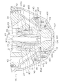
次に、プラズマトーチ1aのプラズマガス通路について説明する。本実施形態においてプラズマガスは、酸素ガスである。ただし、アルゴン、或いは窒素などの他のガスが用いられてもよい。図30は、プラズマトーチ1aの中心軸線に沿った図1と異なる断面図である。図1及び図30において、破線の矢印は、プラズマガスの流れを示している。詳細には、図30において破線の矢印は、メインガスの流れを示している。図1において破線の矢印は、アシストガスの流れを示している。
1.4 Gas passage Next, the plasma gas passage of the plasma torch 1a will be described. In the present embodiment, the plasma gas is oxygen gas. However, other gases such as argon or nitrogen may be used. FIG. 30 is a cross-sectional view different from FIG. 1 taken along the central axis of the plasma torch 1a. In FIG. 1 and FIG. 30, the broken arrows indicate the flow of plasma gas. In detail, broken arrows in FIG. 30 indicate the flow of the main gas. The broken arrow in FIG. 1 indicates the flow of assist gas.

図30に示すように、ベース部33にはメインガス供給管47が接続されている。メインガス供給管47は、ベース部33内の第1メインガス通路MG1を介して、ベース部33と絶縁スリーブ37との間の第2メインガス通路MG2に接続されている。第1メインガス通路MG1は、ベース部33の基端面からベース部33の内周面の段部332に向かって、軸線方向に延びている。第2メインガス通路MG2は、ベース部33の内周面の段部332と絶縁スリーブ37の外周面の段部372との間に形成された環状の通路である。   As shown in FIG. 30, the main gas supply pipe 47 is connected to the base portion 33. The main gas supply pipe 47 is connected to a second main gas passage MG2 between the base portion 33 and the insulating sleeve 37 via the first main gas passage MG1 in the base portion 33. The first main gas passage MG <b> 1 extends in the axial direction from the base end surface of the base portion 33 toward the step portion 332 of the inner circumferential surface of the base portion 33. The second main gas passage MG2 is an annular passage formed between the stepped portion 332 of the inner peripheral surface of the base portion 33 and the stepped portion 372 of the outer peripheral surface of the insulating sleeve 37.

第2メインガス通路MG2は、絶縁スリーブ37内の第3メインガス通路MG3を介して第4メインガス通路MG4に接続されている。第3メインガス通路MG3は、絶縁スリーブ37の外周面の段部372から軸線方向に延びている。第4メインガス通路MG4は、絶縁スリーブ37と、交換部品ユニット2aとの間の環状の通路である。   The second main gas passage MG2 is connected to the fourth main gas passage MG4 via the third main gas passage MG3 in the insulating sleeve 37. The third main gas passage MG3 extends in the axial direction from the step portion 372 of the outer peripheral surface of the insulating sleeve 37. The fourth main gas passage MG4 is an annular passage between the insulating sleeve 37 and the replacement part unit 2a.

図31は、図30における交換部品ユニット2aとその周囲の構成の拡大図である。図31に示すように、第4メインガス通路MG4は、絶縁スリーブ37の内周面と絶縁ガイド7の外周面と電極6の外周面とによって構成される。   31 is an enlarged view of the configuration of the replacement part unit 2a in FIG. 30 and the periphery thereof. As shown in FIG. 31, the fourth main gas passage MG4 is constituted by the inner peripheral surface of the insulating sleeve 37, the outer peripheral surface of the insulating guide 7 and the outer peripheral surface of the electrode 6.

詳細には、絶縁スリーブ37の内周面には、段部373が設けられている。段部373は、絶縁スリーブ37の軸線方向に垂直な面である。交換部品ユニット2aがトーチ本体3に取り付けられた状態で、絶縁ガイド7の外側段部79は、絶縁スリーブ37の内周面の段部373に対して隙間を隔てて配置される。第4メインガス通路MG4は、この絶縁ガイド7の外側段部79と、絶縁スリーブ37の内周面の段部373との間の隙間を通っている。   In more detail, a stepped portion 373 is provided on the inner peripheral surface of the insulating sleeve 37. The stepped portion 373 is a surface perpendicular to the axial direction of the insulating sleeve 37. With the replacement component unit 2 a attached to the torch main body 3, the outer step 79 of the insulating guide 7 is disposed with a gap from the step 373 of the inner peripheral surface of the insulating sleeve 37. The fourth main gas passage MG4 passes through a gap between the outer stepped portion 79 of the insulating guide 7 and the stepped portion 373 of the inner peripheral surface of the insulating sleeve 37.

第4メインガス通路MG4は、上述した第3冷却水通路W3に対してOリングR2によってシールされている。OリングR2は、絶縁スリーブ37の内周面に設けられた凹部374に嵌め込まれている。OリングR2は、絶縁ガイド7の第2外周面76の一部と接触している。すなわち、絶縁ガイド7の第2外周面76は、Oリングと接触するシール面761を有している。第2外周面76においてシール面761よりも先端側の部分は、第3冷却水通路W3内に配置されている。第2外周面76においてシール面761よりも基端側の部分は、第4メインガス通路MG4内に配置されている。第3外周面77も、第2外周面76と同様に、第4メインガス通路MG4内に配置される。   The fourth main gas passage MG4 is sealed by the O-ring R2 with respect to the third cooling water passage W3 described above. The O-ring R2 is fitted in a recess 374 provided on the inner circumferential surface of the insulating sleeve 37. The O-ring R2 is in contact with a part of the second outer peripheral surface 76 of the insulating guide 7. That is, the second outer peripheral surface 76 of the insulating guide 7 has a seal surface 761 in contact with the O-ring. A portion of the second outer circumferential surface 76 on the tip side of the seal surface 761 is disposed in the third coolant passage W3. A portion of the second outer circumferential surface 76 on the proximal side of the seal surface 761 is disposed in the fourth main gas passage MG4. Similarly to the second outer circumferential surface 76, the third outer circumferential surface 77 is also disposed in the fourth main gas passage MG4.

図29に示すように、第4メインガス通路MG4は、上述した第6冷却水通路W6及び第7冷却水通路W7に対してOリングR3によってシールされている。OリングR3は、絶縁スリーブ37の内周面に設けられた凹部375に嵌め込まれている。OリングR3は、電極6のフランジ部63の外周面の一部と接触している。すなわち、フランジ部63の外周面は、OリングR3と接触するシール面631を有する。フランジ部63の外周面においてシール面631よりも先端側の部分は、第4メインガス通路MG4内に配置されている。   As shown in FIG. 29, the fourth main gas passage MG4 is sealed by an O-ring R3 with respect to the sixth cooling water passage W6 and the seventh cooling water passage W7 described above. The O-ring R3 is fitted in a recess 375 provided on the inner peripheral surface of the insulating sleeve 37. The O-ring R 3 is in contact with a part of the outer peripheral surface of the flange portion 63 of the electrode 6. That is, the outer peripheral surface of the flange portion 63 has a seal surface 631 in contact with the O-ring R3. A portion on the tip end side of the seal surface 631 in the outer peripheral surface of the flange portion 63 is disposed in the fourth main gas passage MG4.

図31に示すように、第4メインガス通路MG4は、絶縁ガイド7の複数の連通路703を介して、絶縁ガイド7と電極6との間の第5メインガス通路MG5に接続されている。第5メインガス通路MG5は、絶縁ガイド7の内周面と電極6の外周面との間の環状の通路である。第5メインガス通路MG5は、ノズル8と電極6との間の第6メインガス通路MG6に接続されている。第5メインガス通路MG5の内径は、第6メインガス通路MG6の内径と同じである。第6メインガス通路MG6は、ノズル8の噴射孔831に連通している。   As shown in FIG. 31, the fourth main gas passage MG4 is connected to the fifth main gas passage MG5 between the insulating guide 7 and the electrode 6 via the plurality of communication passages 703 of the insulating guide 7. The fifth main gas passage MG5 is an annular passage between the inner peripheral surface of the insulating guide 7 and the outer peripheral surface of the electrode 6. The fifth main gas passage MG5 is connected to a sixth main gas passage MG6 between the nozzle 8 and the electrode 6. The inner diameter of the fifth main gas passage MG5 is the same as the inner diameter of the sixth main gas passage MG6. The sixth main gas passage MG6 is in communication with the injection hole 831 of the nozzle 8.

メインガスは、メインガスの供給源から、ベース部33内の第1メインガス通路MG1、ベース部33と絶縁スリーブ37との間の第2メインガス通路MG2、絶縁スリーブ37内の第3メインガス通路MG3を通って、絶縁スリーブ37と交換部品ユニット2aとの間の第4メインガス通路MG4に流れる。メインガスは、第4メインガス通路MG4から連通路703を通ることで旋回流となって、第5メインガス通路MG5に噴出される。旋回流となったメインガスは、第6メインガス通路MG6を通って、ノズル8の噴射孔831から噴出される。   The main gas is supplied from the main gas supply source, the first main gas passage MG1 in the base portion 33, the second main gas passage MG2 between the base portion 33 and the insulating sleeve 37, and the third main gas in the insulating sleeve 37 The gas flows through the passage MG3 into the fourth main gas passage MG4 between the insulating sleeve 37 and the replacement part unit 2a. The main gas flows from the fourth main gas passage MG4 through the communication passage 703 to form a swirling flow, and is ejected to the fifth main gas passage MG5. The main gas that has become the swirling flow is ejected from the injection holes 831 of the nozzle 8 through the sixth main gas passage MG6.

図1に示すように、ベース部33にはアシストガス供給管48が接続されている。アシストガス供給管48は、ベース部33内の第1アシストガス通路AG1を介して、ノズル台座36内の第2アシストガス通路AG2に接続されている。第1アシストガス通路AG1は、ベース部33の基端面からベース部33の外周面に向かって延びている。第2アシストガス通路AG2は、ノズル台座36の内周面からノズル台座36の外周面に向かって延びている。   As shown in FIG. 1, an assist gas supply pipe 48 is connected to the base portion 33. The assist gas supply pipe 48 is connected to the second assist gas passage AG2 in the nozzle pedestal 36 via the first assist gas passage AG1 in the base portion 33. The first assist gas passage AG <b> 1 extends from the proximal end surface of the base portion 33 toward the outer peripheral surface of the base portion 33. The second assist gas passage AG2 extends from the inner peripheral surface of the nozzle pedestal 36 toward the outer peripheral surface of the nozzle pedestal 36.

第2アシストガス通路AG2は、ホルダ38内の第3アシストガス通路AG3を介して、ホルダ38と第2リテーナキャップ5との間の第4アシストガス通路AG4に接続されている。第3アシストガス通路AG3は、ホルダ38の内周面から外周面に向かって延びている。第4アシストガス通路AG4は、ホルダ38の外周面と第2リテーナキャップ5の内周面との間の環状の通路である。   The second assist gas passage AG2 is connected to a fourth assist gas passage AG4 between the holder 38 and the second retainer cap 5 via a third assist gas passage AG3 in the holder 38. The third assist gas passage AG3 extends from the inner peripheral surface of the holder 38 toward the outer peripheral surface. The fourth assist gas passage AG4 is an annular passage between the outer peripheral surface of the holder 38 and the inner peripheral surface of the second retainer cap 5.

第4アシストガス通路AG4は、第2リテーナキャップ5内の第5アシストガス通路AG5を介して、第1リテーナキャップ4と第2リテーナキャップ5との間の第6アシストガス通路AG6に接続される。第5アシストガス通路AG5は、第2リテーナキャップ5の内周面から外周面に向かって延びる複数の通路である。第6アシストガス通路AG6は、第1リテーナキャップ4の内周面と第2リテーナキャップ5の外周面との間の環状の通路である。   The fourth assist gas passage AG4 is connected to a sixth assist gas passage AG6 between the first retainer cap 4 and the second retainer cap 5 via a fifth assist gas passage AG5 in the second retainer cap 5 . The fifth assist gas passages AG <b> 5 are a plurality of passages extending from the inner peripheral surface of the second retainer cap 5 toward the outer peripheral surface. The sixth assist gas passage AG6 is an annular passage between the inner peripheral surface of the first retainer cap 4 and the outer peripheral surface of the second retainer cap 5.

図29に示すように、第6アシストガス通路AG6は、シールドキャップ10の複数の連通路105を介して、ノズル8とシールドキャップ10との間の第7アシストガス通路AG7に接続されている。第7アシストガス通路AG7は、ノズル8の噴射孔831及びシールドキャップ10の噴射孔104と連通している。   As shown in FIG. 29, the sixth assist gas passage AG6 is connected to the seventh assist gas passage AG7 between the nozzle 8 and the shield cap 10 via the plurality of communication passages 105 of the shield cap 10. The seventh assist gas passage AG <b> 7 communicates with the injection hole 831 of the nozzle 8 and the injection hole 104 of the shield cap 10.

第6アシストガス通路AG6は、上述した第3冷却水通路W3に対して、OリングR4によってシールされている。OリングR4は、第1リテーナキャップ4の内周面の先端部に設けられた凹部44に嵌め込まれている。OリングR4は、シールドキャップ10の第1外周面13に接触している。すなわち、シールドキャップ10の第1外周面13は、OリングR4と接触するシール面131を有している。   The sixth assist gas passage AG6 is sealed by an O-ring R4 with respect to the above-described third cooling water passage W3. The O-ring R4 is fitted in a recess 44 provided at the tip of the inner peripheral surface of the first retainer cap 4. The O-ring R 4 is in contact with the first outer circumferential surface 13 of the shield cap 10. That is, the first outer circumferential surface 13 of the shield cap 10 has the sealing surface 131 in contact with the O-ring R4.

上述したように絶縁リング9は、圧入によってノズル8に接合されている。また、絶縁リング9は、圧入によってシールドキャップ10に接合されている。このため、第7アシストガス通路AG7は、上述した第3冷却水通路W3に対して、絶縁リング9によってシールされている。   As described above, the insulating ring 9 is joined to the nozzle 8 by press-fitting. In addition, the insulating ring 9 is joined to the shield cap 10 by press fitting. For this reason, the seventh assist gas passage AG7 is sealed by the insulating ring 9 with respect to the above-described third cooling water passage W3.

アシストガスは、アシストガスの供給源から、ベース部33内の第1アシストガス通路AG1、ノズル台座36内の第2アシストガス通路AG2、ホルダ38内の第3アシストガス通路AG3、ホルダ38と第2リテーナキャップ5との間の第4アシストガス通路AG4、第2リテーナキャップ5内の第5アシストガス通路AG5を通って、第1リテーナキャップ4と第2リテーナキャップ5との間の第6アシストガス通路AG6に流れる。アシストガスは、第6アシストガス通路AG6から連通路105を通ることで旋回流となって、第7アシストガス通路AG7に噴出される。旋回流となったアシストガスは、第7アシストガス通路AG7を通って、メインガスと共に、シールドキャップ10の噴射孔104から噴出される。   The assist gas is supplied from an assist gas supply source, a first assist gas passage AG1 in the base portion 33, a second assist gas passage AG2 in the nozzle pedestal 36, a third assist gas passage AG3 in the holder 38, the holder 38 and Through the fourth assist gas passage AG4 between the second retainer cap 5 and the fifth assist gas passage AG5 in the second retainer cap 5, the sixth assist between the first retainer cap 4 and the second retainer cap 5 It flows into the gas passage AG6. The assist gas flows from the sixth assist gas passage AG6 through the communication passage 105 to form a swirling flow, and is ejected into the seventh assist gas passage AG7. The assist gas that has become the swirl flow is ejected from the injection holes 104 of the shield cap 10 together with the main gas through the seventh assist gas passage AG7.

1.5 交換部品ユニットの交換方法
次に、交換部品ユニット2aの交換方法について説明する。交換部品ユニット2aは消耗品である。そのため、交換部品ユニット2aは着脱可能にトーチ本体3に取り付けられており、交換が必要な程度に消耗が進むと、新しいものに交換される。図29に示すように、プラズマトーチ1aでは、第2リテーナキャップ5の開口51の縁部によってシールドキャップ10の段部17が軸線方向に押圧されている。また、シールドキャップ10のフランジ部14が、第1リテーナキャップ4の開口41の縁部と第2リテーナキャップ5の開口51の縁部とによって挟み込まれている。これにより、交換部品ユニット2aが固定されている。このため、交換部品ユニット2aの交換時には、まず、第2リテーナキャップ5が取り外される。
1.5 Replacement Method of Replacement Parts Unit Next, a replacement method of the replacement parts unit 2a will be described. The replacement part unit 2a is a consumable item. Therefore, the replacement part unit 2a is detachably attached to the torch main body 3, and is replaced with a new one when the consumption is advanced to the extent that the replacement is necessary. As shown in FIG. 29, in the plasma torch 1a, the step 17 of the shield cap 10 is pressed in the axial direction by the edge of the opening 51 of the second retainer cap 5. Further, the flange portion 14 of the shield cap 10 is sandwiched by the edge of the opening 41 of the first retainer cap 4 and the edge of the opening 51 of the second retainer cap 5. Thereby, the replacement part unit 2a is fixed. Therefore, when replacing the replacement part unit 2a, the second retainer cap 5 is first removed.

第2リテーナキャップ5が取り外された状態では、交換部品ユニット2aは、OリングR2,R3,R4の弾性力によって保持される。従って、交換部品ユニット2aを第1リテーナキャップ4の開口41から先端側へ引き出すことによって、交換部品ユニット2aの絶縁ガイド7と電極6とが、絶縁スリーブ37から引き出される。その際、センタパイプ20の接触子22は、電極6の内周面に沿って摺動し、電極6がセンタパイプ20から抜き出される。以上のようにして、交換部品ユニット2aをトーチ本体3から一体的に容易に取り外すことができる。   When the second retainer cap 5 is removed, the replacement part unit 2a is held by the elastic force of the O-rings R2, R3 and R4. Therefore, by pulling out the replacement part unit 2 a from the opening 41 of the first retainer cap 4 to the tip side, the insulating guide 7 and the electrode 6 of the replacement part unit 2 a are pulled out from the insulating sleeve 37. At this time, the contacts 22 of the center pipe 20 slide along the inner circumferential surface of the electrode 6, and the electrode 6 is extracted from the center pipe 20. As described above, the replacement part unit 2a can be easily and integrally removed from the torch body 3.

なお、交換部品ユニット2aを第1リテーナキャップ4の開口41から先端側へ引き出す前に、第1リテーナキャップ4を緩めるとよい。これにより、シールドキャップ10のフランジ部14が第1リテーナキャップ4の開口41の縁部に引っ掛かって押し出される。これにより、交換部品ユニット2aを容易に取り外すことができる。   Before the replacement part unit 2 a is pulled out from the opening 41 of the first retainer cap 4 to the distal end side, the first retainer cap 4 may be loosened. Thereby, the flange portion 14 of the shield cap 10 is caught on the edge of the opening 41 of the first retainer cap 4 and pushed out. Thereby, the replacement part unit 2a can be easily removed.

新たな交換部品ユニット2aを取り付ける際には、交換部品ユニット2aを第1リテーナキャップ4の開口41から基端側へ向けて挿入する。これにより、交換部品ユニット2aの電極6と絶縁ガイド7とが、絶縁スリーブ37内に挿入される。その際、センタパイプ20が電極6内に挿入され、センタパイプ20の接触子22は、電極6の内周面に沿って摺動する。   When mounting a new replacement part unit 2 a, the replacement part unit 2 a is inserted toward the proximal end side from the opening 41 of the first retainer cap 4. Thereby, the electrode 6 of the replacement part unit 2 a and the insulation guide 7 are inserted into the insulation sleeve 37. At that time, the center pipe 20 is inserted into the electrode 6, and the contact 22 of the center pipe 20 slides along the inner peripheral surface of the electrode 6.

そして、第2リテーナキャップ5が第1リテーナキャップ4に取り付けられると、第2リテーナキャップ5の開口51の縁部が、シールドキャップ10の段部17を基端側へ向けて押圧する。これにより、電極6の基端面601が電極台座34の先端面342に接触するまで、交換部品ユニット2aが基端側へ向けて押し込まれる。そして、第1リテーナキャップ4の開口41の縁部と、第2リテーナキャップ5の開口51の縁部とによってシールドキャップ10のフランジ部14が挟み込まれて保持されることにより、交換部品ユニット2aが、固定される。   Then, when the second retainer cap 5 is attached to the first retainer cap 4, the edge of the opening 51 of the second retainer cap 5 presses the step 17 of the shield cap 10 toward the proximal end. As a result, the replacement component unit 2a is pushed toward the proximal end side until the proximal end surface 601 of the electrode 6 contacts the distal end surface 342 of the electrode pedestal 34. Then, the flange portion 14 of the shield cap 10 is sandwiched and held by the edge portion of the opening 41 of the first retainer cap 4 and the edge portion of the opening 51 of the second retainer cap 5, whereby the replacement component unit 2 a , Fixed.

以上説明した本実施形態に係るプラズマトーチ1bでは、センタパイプ20の接触子22が電極6の内周面に接触することで電極6に通電する。従って、従来のプラズマトーチのように、電極6の基端側筒部と電極台座34の内周面とを接続するための構造が不要となる。このため、電極6或いは電極台座34の構造を簡素化することができる。また、電極6と電極台座34とを接続するためのネジ構造が不要となることで、専用の工具無しで容易に電極6の着脱を行うことができる。さらに、通電不良が生じてもトーチ本体3の交換が不要である。   In the plasma torch 1 b according to the present embodiment described above, the contact 22 of the center pipe 20 contacts the inner peripheral surface of the electrode 6 so that the electrode 6 is energized. Therefore, a structure for connecting the proximal end side cylindrical portion of the electrode 6 and the inner peripheral surface of the electrode pedestal 34 as in the conventional plasma torch is not necessary. For this reason, the structure of the electrode 6 or the electrode pedestal 34 can be simplified. Further, since the screw structure for connecting the electrode 6 and the electrode base 34 is not necessary, the electrode 6 can be easily attached and detached without a dedicated tool. Furthermore, even if a current failure occurs, replacement of the torch body 3 is unnecessary.

接触子22は、パイプ本体21の径方向に押圧されることで反力を生じるように弾性を有している。このため、接触子22は、弾性によって電極6の内周面に付勢されている。このため、接触子22と電極6とを安定的に接触させることができる。これにより、接触子22と電極6とを安定的に通電させることができる。   The contactor 22 has elasticity so as to generate a reaction force by being pressed in the radial direction of the pipe main body 21. Therefore, the contact 22 is urged to the inner peripheral surface of the electrode 6 by elasticity. Therefore, the contact 22 and the electrode 6 can be stably brought into contact with each other. Thereby, the contactor 22 and the electrode 6 can be stably energized.

接触子22は、パイプ本体21と別体であり、パイプ本体21の外周面に取り付けられる。このため、接触子22が損傷したときには、接触子22のみを交換することができる。これにより、コストを低減することができる。   The contacts 22 are separate from the pipe main body 21 and attached to the outer peripheral surface of the pipe main body 21. Therefore, when the contact 22 is damaged, only the contact 22 can be replaced. This can reduce the cost.

電極6の内部通路65は、内部通路65の入口に向かって径方向に拡大するテーパ部652を含む。このため、内部通路65に接触子22を容易に挿入することができる。   The inner passage 65 of the electrode 6 includes a tapered portion 652 that expands radially towards the inlet of the inner passage 65. Therefore, the contact 22 can be easily inserted into the internal passage 65.

第1通電面603は、テーパ部652の先端側においてテーパ部652に隣接して配置される。このため、センタパイプ20を電極6に対して出し入れする際に、接触子22が内部通路65と摺動する距離を小さくすることができる。これにより、接触子22及び電極6の磨耗を抑えることができる。また、接触子22は電極6内の冷却水通路に挿入されているので、運転中は冷却水の水流により冷却される。そのため、接触子22が小さな電気導体としての断面積であっても大電流の通電が可能となる。   The first conductive surface 603 is disposed adjacent to the tapered portion 652 on the tip end side of the tapered portion 652. Therefore, when the center pipe 20 is taken in and out of the electrode 6, the distance in which the contact 22 slides with the internal passage 65 can be reduced. Thereby, wear of the contactor 22 and the electrode 6 can be suppressed. Further, since the contact 22 is inserted into the cooling water passage in the electrode 6, it is cooled by the flow of the cooling water during operation. Therefore, even if the contact 22 has a small cross section as a small electric conductor, a large current can be supplied.

2. 第2実施形態
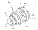
次に、第2実施形態に係るプラズマトーチ1bについて説明する。図32は、第2実施形態に係るプラズマトーチ1bの中心軸線に沿った断面図である。図33は、第2実施形態に係る交換部品ユニット2bの断面図である。図34及び図35は、交換部品ユニット2bの斜視図である。図36及び図37は、第2実施形態に係るノズル8の斜視図である。
2. Second Embodiment Next, a plasma torch 1b according to a second embodiment will be described. FIG. 32 is a cross-sectional view of the plasma torch 1b according to the second embodiment, taken along the central axis. FIG. 33 is a cross-sectional view of the replacement part unit 2b according to the second embodiment. 34 and 35 are perspective views of the replacement part unit 2b. 36 and 37 are perspective views of the nozzle 8 according to the second embodiment.

図33に示すように、ノズル8の第1外周面85は凹部851を有する。凹部851は、第2ノズル部82に設けられている。凹部851は、ノズル8の径方向内方に向かって凹んでおり、ノズル8の周方向に延びている。ノズル8の軸線方向において、凹部851は、電極6の先端と略同じ位置に配置される。凹部851の底部の外径は、ノズル8の内周面812の内径よりも小さい。   As shown in FIG. 33, the first outer peripheral surface 85 of the nozzle 8 has a recess 851. The recess 851 is provided in the second nozzle portion 82. The recess 851 is recessed inward in the radial direction of the nozzle 8 and extends in the circumferential direction of the nozzle 8. In the axial direction of the nozzle 8, the recess 851 is disposed at substantially the same position as the tip of the electrode 6. The outer diameter of the bottom of the recess 851 is smaller than the inner diameter of the inner circumferential surface 812 of the nozzle 8.

凹部851は、基端側の第1壁面852と、先端側の第2壁面853とを有する。第1壁面852は、ノズル8の径方向に対して傾斜している。第2壁面853は、ノズル8の径方向に延びている。図32に示すように、第1壁面852は、第1リテーナキャップ4の傾斜した内周面と平行に延びている。凹部851は、第3冷却水通路W3内に配置されている。   The recess 851 has a first wall surface 852 on the proximal side and a second wall surface 853 on the distal side. The first wall surface 852 is inclined with respect to the radial direction of the nozzle 8. The second wall surface 853 extends in the radial direction of the nozzle 8. As shown in FIG. 32, the first wall surface 852 extends in parallel with the inclined inner circumferential surface of the first retainer cap 4. The recess 851 is disposed in the third coolant passage W3.

本実施形態では、第1リテーナキャップ4には、第3冷却水通路W3に連通する複数の孔43が設けられている。第1リテーナキャップ4の孔43は、第1リテーナキャップ4と第2リテーナキャップ5との間の環状の冷却水通路W12に連通している。ノズル8の軸線方向において、凹部851は、第1リテーナキャップ4の孔43と略同じ位置に配置される。   In the present embodiment, the first retainer cap 4 is provided with a plurality of holes 43 communicating with the third coolant passage W3. The hole 43 of the first retainer cap 4 is in communication with the annular cooling water passage W12 between the first retainer cap 4 and the second retainer cap 5. In the axial direction of the nozzle 8, the recess 851 is disposed at substantially the same position as the hole 43 of the first retainer cap 4.

交換部品ユニット2b及びプラズマトーチ1bの他の構成については第1実施形態の交換部品ユニット2a及びプラズマトーチ1aと同様である。   The other configurations of the replacement part unit 2 b and the plasma torch 1 b are the same as those of the replacement part unit 2 a and the plasma torch 1 a of the first embodiment.

以上説明した第2実施形態では、ノズル8に凹部851が設けられているので、ノズル8において冷却水と接触する表面積を拡大することができる。そのため、ノズル8の冷却性を向上させることができる。また、凹部851が第1リテーナキャップ4の孔43と略同じ位置に配置されるので、ノズル8の冷却性をさらに向上させることができる。また、冷却水通路W12は第2リテーナキャップ5も水冷できる。このため、本実施形態に係る交換部品ユニット2bは、大電流を用いるプラズマ切断に好適である。   In the second embodiment described above, since the concave portion 851 is provided in the nozzle 8, the surface area of the nozzle 8 in contact with the cooling water can be expanded. Therefore, the cooling property of the nozzle 8 can be improved. In addition, since the recess 851 is disposed at substantially the same position as the hole 43 of the first retainer cap 4, the cooling performance of the nozzle 8 can be further improved. Further, the cooling water passage W12 can also cool the second retainer cap 5 with water. For this reason, the replacement part unit 2b according to this embodiment is suitable for plasma cutting using a large current.

3. 他の実施形態
以上、本発明の一実施形態について説明したが、本発明は上記実施形態に限定されるものではなく、発明の要旨を逸脱しない範囲で種々の変更が可能である。
3. Other Embodiments Although one embodiment of the present invention has been described above, the present invention is not limited to the above embodiment, and various modifications can be made without departing from the scope of the invention.

交換部品ユニット2a,2bの構造が変更されてもよい。トーチ本体3、第1リテーナキャップ4、及び第2リテーナキャップ5の構造が変更されてもよい。パイプ本体21或いは接触子22の構造が変更されてもよい。   The structure of the replacement parts unit 2a, 2b may be changed. The structures of the torch body 3, the first retainer cap 4 and the second retainer cap 5 may be changed. The structure of the pipe body 21 or the contact 22 may be changed.

電極6と絶縁ガイド7とノズル8とは互いに着脱可能に接合されてもよい。   The electrode 6, the insulating guide 7 and the nozzle 8 may be detachably joined to each other.

電極6と絶縁ガイド7とは、圧入ではなく接着によって接合されてもよい。絶縁ガイド7とノズル8とは、圧入ではなく接着によって接合されてもよい。ノズル8と絶縁リング9とは、圧入ではなく接着によって接合されてもよい。絶縁リング9とシールドキャップ10とは、圧入ではなく接着によって接合されてもよい。   The electrode 6 and the insulating guide 7 may be bonded not by press-fitting but by adhesion. The insulation guide 7 and the nozzle 8 may be bonded not by press-fitting but by adhesion. The nozzle 8 and the insulating ring 9 may be joined not by press-fitting but by adhesion. The insulating ring 9 and the shield cap 10 may be bonded not by press-fitting but by adhesion.

絶縁リング9とシールドキャップ10とは、交換部品ユニット2a,2bに含まれなくてもよい。すなわち、電極6と絶縁ガイド7とノズル8とによって交換部品ユニットが構成されてもよい。また、絶縁リング9とシールドキャップ10とは、この交換部品ユニットに対して着脱容易に取り付けられてもよい。   The insulating ring 9 and the shield cap 10 may not be included in the replacement part units 2a and 2b. That is, the replacement part unit may be configured by the electrode 6, the insulating guide 7 and the nozzle 8. Also, the insulating ring 9 and the shield cap 10 may be easily attached to and detached from the replacement part unit.

絶縁ガイド7内のガス通路の内径は、ノズル8の内径よりも大きくてもよい。すなわち、図38に示すように、絶縁ガイド7内の第5メインガス通路MG5の内径は、ノズル8内の第6メインガス通路MG6の内径よりも大きくてもよい。   The inner diameter of the gas passage in the insulating guide 7 may be larger than the inner diameter of the nozzle 8. That is, as shown in FIG. 38, the inner diameter of the fifth main gas passage MG5 in the insulating guide 7 may be larger than the inner diameter of the sixth main gas passage MG6 in the nozzle 8.

本発明によれば、専用の工具無しで容易に電極の着脱が可能であり、電極或いは電極台座の構造を簡素化することができ、さらに通電不良が生じてもトーチ本体の交換が不要なプラズマトーチ用センタパイプ、接触子、電極、及びプラズマトーチを提供することができる。   According to the present invention, the electrode can be easily attached and detached without a dedicated tool, the structure of the electrode or the electrode base can be simplified, and the plasma does not require replacement of the torch main body even if a current failure occurs. A center pipe for torch, a contact, an electrode, and a plasma torch can be provided.

20 センタパイプ
6 電極
21 パイプ本体
22 接触子
261 凹部
281 第1環部
282 第2環部
291 湾曲部
292 スリット
28 取付部
29 接触部
65 内部通路
603 第1通電面
601 第2通電面
652 テーパ部
61 電極本体部
63 フランジ部
Reference Signs List 20 center pipe 6 electrode 21 pipe main body 22 contactor 261 recessed portion 281 first ring portion 282 second ring portion 291 curved portion 292 slit 28 mounting portion 29 contact portion 65 internal passage 603 first conductive surface 601 second conductive surface 652 tapered portion 61 electrode body portion 63 flange portion

Claims (14)

ベース部と電極とを有するプラズマ切断用のプラズマトーチに用いられ、前記電極に挿入され、前記電極内に冷却水を供給するためのセンタパイプであって、
前記ベース部を介して前記プラズマトーチ外の電源と電気的に接続され、冷却水通路を内部に有し、導電体で形成されたパイプ本体と、
前記パイプ本体の外周面に設けられ、前記電極の内周面に接触することで前記電極に通電され、前記パイプ本体の径方向に押圧されることで反力を生じるように弾性を有し、導電体で形成された接触子と、
を備えるプラズマトーチ用センタパイプ。
A center pipe for use in a plasma torch for plasma cutting having a base portion and an electrode, inserted into the electrode, for supplying cooling water into the electrode,
A pipe body electrically connected to a power supply outside the plasma torch via the base portion, having a cooling water passage inside, and formed of a conductor;
It is provided on the outer peripheral surface of the pipe main body and has elasticity so as to generate a reaction force by being energized in the radial direction of the pipe main body by being energized in contact with the inner peripheral surface of the electrode. A contact made of a conductor,
Center pipe for plasma torches.
前記接触子は、前記パイプ本体と別体であり、前記パイプ本体の外周面に取り付けられる、
請求項1に記載のプラズマトーチ用センタパイプ。
The contact is separate from the pipe body, and is attached to the outer peripheral surface of the pipe body.
The center pipe for a plasma torch according to claim 1.
前記パイプ本体の外周面は、前記接触子が取り付けられる凹部を有する、
請求項2に記載のプラズマトーチ用センタパイプ。
The outer peripheral surface of the pipe body has a recess to which the contact is attached,
The center pipe for a plasma torch according to claim 2.
前記接触子は、
第1環部と、
前記接触子の軸線方向に前記第1環部から離れて配置される第2環部と、
前記第1環部と前記第2環部とを連結し、前記接触子の径方向外方に向かって膨出する複数の湾曲部と、
を有する、
請求項1から3のいずれかに記載のプラズマトーチ用センタパイプ。
The contact is
The first ring portion,
A second ring portion disposed apart from the first ring portion in the axial direction of the contact;
A plurality of curved portions that connect the first ring portion and the second ring portion and bulge outward in the radial direction of the contact;
Have
The center pipe for a plasma torch according to any one of claims 1 to 3.
前記接触子は、複数の前記湾曲部の間に設けられ、前記接触子の軸線方向に延びる複数のスリットを有する、
請求項4に記載のプラズマトーチ用センタパイプ。
The contact is provided between the plurality of curved portions, and has a plurality of slits extending in the axial direction of the contact.
The center pipe for a plasma torch according to claim 4.
電極と、前記電極に挿入され前記電極内に冷却水を供給するための冷却水通路を内部に有するパイプ本体と、を有するプラズマ切断用のプラズマトーチに用いられる接触子であって、
前記パイプ本体の外周面に取り付けられる取付部と、
前記電極の内周面に接触させるための接触部と、
を備えるプラズマトーチ用接触子。
A contactor for use in a plasma torch for plasma cutting, comprising: an electrode; and a pipe body having a cooling water passage inserted therein and supplying a cooling water passage into the electrode.
An attaching portion attached to an outer peripheral surface of the pipe body;
A contact portion for contacting the inner circumferential surface of the electrode;
Contact for plasma torch comprising.
前記接触部は、前記接触子の径方向に押圧されることで反力を生じるように弾性を有する、
請求項6に記載のプラズマトーチ用接触子。
The contact portion has elasticity so as to generate a reaction force by being pressed in the radial direction of the contact.
A contact for a plasma torch according to claim 6.
前記取付部は、
第1環部と、
前記接触子の軸線方向に前記第1環部から離れて配置される第2環部と、
を有し、
前記接触部は、
前記第1環部と前記第2環部とを連結し、前記接触子の径方向外方に向かって膨出する複数の湾曲部
を有する、
請求項6又は7に記載のプラズマトーチ用接触子。
The mounting portion is
The first ring portion,
A second ring portion disposed apart from the first ring portion in the axial direction of the contact;
Have
The contact portion is
A plurality of curved portions connecting the first ring portion and the second ring portion and bulging outward in the radial direction of the contact;
A contact for a plasma torch according to claim 6 or 7.
前記接触部は、
複数の前記湾曲部の間に設けられ、前記接触子の軸線方向に延びる複数のスリットをさらに有する、
請求項8に記載のプラズマトーチ用接触子
The contact portion is
And a plurality of slits provided between the plurality of curved portions and extending in the axial direction of the contact.
A contact for a plasma torch according to claim 8.
請求項1から5のいずれかに記載の前記センタパイプと、
前記センタパイプが挿入される内部通路を有する電極と、
を備え
前記内部通路の内周面の少なくとも一部は、前記センタパイプに設けられ弾性を有する接触子と接触する第1通電面を形成する、
を備えるプラズマトーチ。
The center pipe according to any one of claims 1 to 5,
An electrode having an internal passage into which the center pipe is inserted ;
Equipped with
At least a portion of the inner peripheral surface of the internal passage forms a first current-carrying surface provided on the center pipe and in contact with an elastic contact.
Plasma torch equipped with
前記電極の基端面は、第2通電面を含む、
請求項10に記載のプラズマトーチ。
The proximal end face of the electrode includes a second conducting surface,
Plasma torch according to claim 10.
前記電極の基端の端面は、前記内部通路の入口を含み、
前記内部通路の内周面は、前記内部通路の前記入口に向かって径方向に拡大するテーパ部を含む、
請求項10又は11に記載のプラズマトーチ。
The proximal end face of the electrode includes the inlet of the internal passage,
An inner circumferential surface of the inner passage includes a tapered portion radially expanding toward the inlet of the inner passage.
Plasma torch according to claim 10 or 11.
前記第1通電面は、前記テーパ部の先端側において前記テーパ部に隣接して配置される、
請求項12に記載のプラズマトーチ。
The first electric conduction surface is disposed adjacent to the tapered portion on the tip end side of the tapered portion.
Plasma torch according to claim 12.
前記電極の先端を含む電極本体部と、
前記電極の基端を含み、前記電極本体部よりも大きな外径を有するフランジ部と、
を備え、
前記電極の軸線方向において、前記テーパ部は、前記フランジ部よりも短い、
請求項12又は13に記載のプラズマトーチ。
An electrode body including a tip of the electrode;
A flange portion including a proximal end of the electrode and having an outer diameter larger than that of the electrode body portion;
Equipped with
In the axial direction of the electrode, the tapered portion is shorter than the flange portion,
Plasma torch according to claim 12 or 13.
JP2015017463A 2015-01-30 2015-01-30 Center pipe for plasma torch, contactor, electrode, and plasma torch Active JP6522967B2 (en)

Priority Applications (9)

Application Number Priority Date Filing Date Title
JP2015017463A JP6522967B2 (en) 2015-01-30 2015-01-30 Center pipe for plasma torch, contactor, electrode, and plasma torch
KR1020197001232A KR102042546B1 (en) 2015-01-30 2015-12-04 Center pipe for plasma torch, contactor, electrode, and plasma torch
KR1020197001231A KR102042545B1 (en) 2015-01-30 2015-12-04 Center pipe for plasma torch, contactor, electrode, and plasma torch
KR1020167036908A KR101940595B1 (en) 2015-01-30 2015-12-04 Center pipe for plasma torch, contactor, electrode, and plasma torch
DE112015003758.6T DE112015003758B4 (en) 2015-01-30 2015-12-04 CENTRAL TUBE FOR A PLASMA TORCH, CONTACT PIECE, ELECTRODE AND PLASMA TORCH
PCT/JP2015/084161 WO2016121227A1 (en) 2015-01-30 2015-12-04 Center pipe for plasma torch, contactor, electrode, and plasma torch
US15/325,313 US10232460B2 (en) 2015-01-30 2015-12-04 Center pipe for plasma torch, contact piece, electrode, and plasma torch
CN201580035372.0A CN106660159B (en) 2015-01-30 2015-12-04 Central tube, contact element, electrode and plasma torch for plasma torch
US16/264,838 US11014188B2 (en) 2015-01-30 2019-02-01 Center pipe for plasma torch, electrode, and plasma torch

Applications Claiming Priority (1)

Application Number Priority Date Filing Date Title
JP2015017463A JP6522967B2 (en) 2015-01-30 2015-01-30 Center pipe for plasma torch, contactor, electrode, and plasma torch

Publications (3)

Publication Number Publication Date
JP2016140871A JP2016140871A (en) 2016-08-08
JP2016140871A5 JP2016140871A5 (en) 2019-05-09
JP6522967B2 true JP6522967B2 (en) 2019-05-29

Family

ID=56542862

Family Applications (1)

Application Number Title Priority Date Filing Date
JP2015017463A Active JP6522967B2 (en) 2015-01-30 2015-01-30 Center pipe for plasma torch, contactor, electrode, and plasma torch

Country Status (6)

Country Link
US (2) US10232460B2 (en)
JP (1) JP6522967B2 (en)
KR (3) KR102042545B1 (en)
CN (1) CN106660159B (en)
DE (1) DE112015003758B4 (en)
WO (1) WO2016121227A1 (en)

Families Citing this family (10)

* Cited by examiner, † Cited by third party
Publication number Priority date Publication date Assignee Title
US10721812B2 (en) * 2012-08-06 2020-07-21 Hypertherm, Inc. Asymmetric consumables for a plasma arc torch
JP6522968B2 (en) * 2015-01-30 2019-05-29 株式会社小松製作所 Insulation guide for plasma torch and replacement part unit
JP6636249B2 (en) * 2015-01-30 2020-01-29 株式会社小松製作所 Replacement parts unit for plasma torch
US10561010B2 (en) * 2015-12-21 2020-02-11 Hypertherm, Inc. Internally energized electrode of a plasma arc torch
FR3067559B1 (en) * 2017-06-07 2019-07-05 Akryvia PLASMA CUTTING METHOD AND TORCH FOR CARRYING OUT SAID METHOD
JP6918603B2 (en) * 2017-06-28 2021-08-11 コマツ産機株式会社 Control method of 3D laser machine and 3D laser machine
US11134559B2 (en) 2017-07-04 2021-09-28 Norsk Titanium As Plasma torch system
JP7344227B2 (en) * 2018-06-12 2023-09-13 アジレント・テクノロジーズ・インク ICP spectrometer torch with removable integral injector
CN112413114B (en) * 2019-08-23 2022-04-05 上海汽车集团股份有限公司 Hydraulic adjusting system for CVT and hydraulic valve thereof
WO2022108625A1 (en) * 2020-11-17 2022-05-27 American Torch Tip Company Threadless electrode with high contact for use in plasma cutting torch

Family Cites Families (17)

* Cited by examiner, † Cited by third party
Publication number Priority date Publication date Assignee Title
JPH0314076U (en) 1989-06-20 1991-02-13
US5637242A (en) 1994-08-04 1997-06-10 Electro-Plasma, Inc. High velocity, high pressure plasma gun
US5841095A (en) * 1996-10-28 1998-11-24 Hypertherm, Inc. Apparatus and method for improved assembly concentricity in a plasma arc torch
US5756959A (en) * 1996-10-28 1998-05-26 Hypertherm, Inc. Coolant tube for use in a liquid-cooled electrode disposed in a plasma arc torch
US5906758A (en) * 1997-09-30 1999-05-25 The Esab Group, Inc. Plasma arc torch
US6320156B1 (en) 1999-05-10 2001-11-20 Komatsu Ltd. Plasma processing device, plasma torch and method for replacing components of same
JP3625040B2 (en) 1999-08-11 2005-03-02 株式会社小松製作所 Plasma processing machine, plasma torch and method for attaching / detaching the parts
US6852944B2 (en) * 2003-04-07 2005-02-08 Thermal Dynamics Corporation Retractable electrode coolant tube
US20080116179A1 (en) 2003-04-11 2008-05-22 Hypertherm, Inc. Method and apparatus for alignment of components of a plasma arc torch
US6946617B2 (en) * 2003-04-11 2005-09-20 Hypertherm, Inc. Method and apparatus for alignment of components of a plasma arc torch
US8089025B2 (en) * 2007-02-16 2012-01-03 Hypertherm, Inc. Gas-cooled plasma arc cutting torch
US8866038B2 (en) * 2007-01-23 2014-10-21 Hypertherm, Inc. Consumable component parts for a plasma torch
US8420975B2 (en) * 2007-07-12 2013-04-16 Komatsu Industries Corp. Plasma torch, plasma torch nozzle, and plasma-working machine
US20120031881A1 (en) * 2010-08-09 2012-02-09 The Esab Group, Inc. Blow-Back Plasma Arc Torch With Shield Fluid-Cooled Electrode
JP6082967B2 (en) * 2012-12-27 2017-02-22 株式会社小松製作所 Plasma cutting machine and cutting method
ES2923761T3 (en) * 2013-05-16 2022-09-30 Kjellberg Stiftung Multi-part insulating insert for a plasma arc torch, torch, and associated assemblies using the same and associated methods
US10561010B2 (en) * 2015-12-21 2020-02-11 Hypertherm, Inc. Internally energized electrode of a plasma arc torch

Also Published As

Publication number Publication date
US20170182585A1 (en) 2017-06-29
JP2016140871A (en) 2016-08-08
US20190160584A1 (en) 2019-05-30
WO2016121227A1 (en) 2016-08-04
KR102042546B1 (en) 2019-11-08
CN106660159A (en) 2017-05-10
DE112015003758B4 (en) 2022-01-27
CN106660159B (en) 2019-12-13
US11014188B2 (en) 2021-05-25
KR102042545B1 (en) 2019-11-08
DE112015003758T5 (en) 2017-07-13
KR20170012474A (en) 2017-02-02
US10232460B2 (en) 2019-03-19
KR20190006615A (en) 2019-01-18
KR101940595B1 (en) 2019-01-21
KR20190006616A (en) 2019-01-18

Similar Documents

Publication Publication Date Title
JP6522967B2 (en) Center pipe for plasma torch, contactor, electrode, and plasma torch
JP6636249B2 (en) Replacement parts unit for plasma torch
JP4607852B2 (en) Plasma arc torch and assembly and disassembly method of plasma arc torch
JP5567071B2 (en) Plasma torch nozzle
MX2014005807A (en) Gmaw manual/robotic arc welding mig gun with connector for conductor tube.
JP6902587B2 (en) Replacement parts unit for plasma torch
JP6522968B2 (en) Insulation guide for plasma torch and replacement part unit
JP6998208B2 (en) Plasma torch nozzle and replacement parts unit
JP6910116B2 (en) Manufacturing method of insulation guide for plasma torch
WO1998034441A1 (en) Plasma torch
JP2000343228A (en) Plasma torch and its parts
JPH0327309B2 (en)

Legal Events

Date Code Title Description
A621 Written request for application examination

Free format text: JAPANESE INTERMEDIATE CODE: A621

Effective date: 20171207

A521 Request for written amendment filed

Free format text: JAPANESE INTERMEDIATE CODE: A523

Effective date: 20190326

TRDD Decision of grant or rejection written
A01 Written decision to grant a patent or to grant a registration (utility model)

Free format text: JAPANESE INTERMEDIATE CODE: A01

Effective date: 20190409

A61 First payment of annual fees (during grant procedure)

Free format text: JAPANESE INTERMEDIATE CODE: A61

Effective date: 20190425

R150 Certificate of patent or registration of utility model

Ref document number: 6522967

Country of ref document: JP

Free format text: JAPANESE INTERMEDIATE CODE: R150

R250 Receipt of annual fees

Free format text: JAPANESE INTERMEDIATE CODE: R250