EP2339865A2 - Bracket device - Google Patents
Bracket device Download PDFInfo
- Publication number
- EP2339865A2 EP2339865A2 EP10189436A EP10189436A EP2339865A2 EP 2339865 A2 EP2339865 A2 EP 2339865A2 EP 10189436 A EP10189436 A EP 10189436A EP 10189436 A EP10189436 A EP 10189436A EP 2339865 A2 EP2339865 A2 EP 2339865A2
- Authority
- EP
- European Patent Office
- Prior art keywords
- bracket device
- amplifier
- extension members
- distal ends
- securing hardware
- Prior art date
- Legal status (The legal status is an assumption and is not a legal conclusion. Google has not performed a legal analysis and makes no representation as to the accuracy of the status listed.)
- Withdrawn
Links
Images

Classifications
-
- H—ELECTRICITY
- H04—ELECTRIC COMMUNICATION TECHNIQUE
- H04R—LOUDSPEAKERS, MICROPHONES, GRAMOPHONE PICK-UPS OR LIKE ACOUSTIC ELECTROMECHANICAL TRANSDUCERS; ELECTRIC HEARING AIDS; PUBLIC ADDRESS SYSTEMS
- H04R1/00—Details of transducers, loudspeakers or microphones
- H04R1/02—Casings; Cabinets ; Supports therefor; Mountings therein
-
- F—MECHANICAL ENGINEERING; LIGHTING; HEATING; WEAPONS; BLASTING
- F16—ENGINEERING ELEMENTS AND UNITS; GENERAL MEASURES FOR PRODUCING AND MAINTAINING EFFECTIVE FUNCTIONING OF MACHINES OR INSTALLATIONS; THERMAL INSULATION IN GENERAL
- F16M—FRAMES, CASINGS OR BEDS OF ENGINES, MACHINES OR APPARATUS, NOT SPECIFIC TO ENGINES, MACHINES OR APPARATUS PROVIDED FOR ELSEWHERE; STANDS; SUPPORTS
- F16M13/00—Other supports for positioning apparatus or articles; Means for steadying hand-held apparatus or articles
- F16M13/02—Other supports for positioning apparatus or articles; Means for steadying hand-held apparatus or articles for supporting on, or attaching to, an object, e.g. tree, gate, window-frame, cycle
-
- G—PHYSICS
- G10—MUSICAL INSTRUMENTS; ACOUSTICS
- G10G—REPRESENTATION OF MUSIC; RECORDING MUSIC IN NOTATION FORM; ACCESSORIES FOR MUSIC OR MUSICAL INSTRUMENTS NOT OTHERWISE PROVIDED FOR, e.g. SUPPORTS
- G10G5/00—Supports for musical instruments
-
- G—PHYSICS
- G10—MUSICAL INSTRUMENTS; ACOUSTICS
- G10H—ELECTROPHONIC MUSICAL INSTRUMENTS; INSTRUMENTS IN WHICH THE TONES ARE GENERATED BY ELECTROMECHANICAL MEANS OR ELECTRONIC GENERATORS, OR IN WHICH THE TONES ARE SYNTHESISED FROM A DATA STORE
- G10H1/00—Details of electrophonic musical instruments
- G10H1/32—Constructional details
-
- H—ELECTRICITY
- H05—ELECTRIC TECHNIQUES NOT OTHERWISE PROVIDED FOR
- H05K—PRINTED CIRCUITS; CASINGS OR CONSTRUCTIONAL DETAILS OF ELECTRIC APPARATUS; MANUFACTURE OF ASSEMBLAGES OF ELECTRICAL COMPONENTS
- H05K5/00—Casings, cabinets or drawers for electric apparatus
- H05K5/02—Details
- H05K5/0204—Mounting supporting structures on the outside of casings
-
- A—HUMAN NECESSITIES
- A47—FURNITURE; DOMESTIC ARTICLES OR APPLIANCES; COFFEE MILLS; SPICE MILLS; SUCTION CLEANERS IN GENERAL
- A47B—TABLES; DESKS; OFFICE FURNITURE; CABINETS; DRAWERS; GENERAL DETAILS OF FURNITURE
- A47B96/00—Details of cabinets, racks or shelf units not covered by a single one of groups A47B43/00 - A47B95/00; General details of furniture
- A47B96/06—Brackets or similar supporting means for cabinets, racks or shelves
- A47B96/063—C-shaped brackets for gripping the shelf edge
-
- Y—GENERAL TAGGING OF NEW TECHNOLOGICAL DEVELOPMENTS; GENERAL TAGGING OF CROSS-SECTIONAL TECHNOLOGIES SPANNING OVER SEVERAL SECTIONS OF THE IPC; TECHNICAL SUBJECTS COVERED BY FORMER USPC CROSS-REFERENCE ART COLLECTIONS [XRACs] AND DIGESTS
- Y10—TECHNICAL SUBJECTS COVERED BY FORMER USPC
- Y10T—TECHNICAL SUBJECTS COVERED BY FORMER US CLASSIFICATION
- Y10T29/00—Metal working
- Y10T29/49—Method of mechanical manufacture
- Y10T29/49826—Assembling or joining
Definitions
- the present invention involves a bracket which is remarkable in its simplicity and yet provides a way to removably secure devices to amplifier housings which are traditionally employed with portable amplification
- a device such as a control box, remains atop the amplifier secured from inadvertent abuse but which is readily removable therefrom without need for tools or other elaborate securing means
- Amplifiers used by professional entertainers are oftentimes of a common configuration.
- Such a device is depicted in the figures which constitute the present invention
- amplifier 11 is shown having front 15, back 16, bottom 12, right side 13, left side 14 and top 17
- a handle is applied to top 17 of amplifier 11 in the form of spaced apart securing hardware 18 and 19 and handle 20 sized to enable a user to grip handle 20 with one hand wrapping one's fingers about handle 20 in order to move amplifier 11 as needed
- control box 21 in the form of a 1U signal processor is depicted
- the signal processor shown is a rectangular unit measuring 1 3 ⁇ 4" x 19" x 10" which is usually a rack mounted unit employed to tailor the amplifier signal in order to achieve the acoustic effect sought by the musician Controllers 21 are so commonly used that it is assumed that whenever a musician is employing amplifier 11, that control box 21 would be routinely associated therewith
- control box 21 On a crowded stage oftentimes having multiple performers who can move about during their performance, situating control box 21 appropriately can prove challenging Wires must be connected between control box 21 and amplifier I and the challenge remains as to where to put the control box such that it will not represent a hazard to the performer nor be damaged by the performer inadvertently kicking or stepping upon it when in use. If one was to simply place control box 21 on top 17 of amplifier 11, it could easily fall to the ground when it or the amplifier is inadvertently bumped or nudged Not only would this prove costly in the event that the control box was damaged but could also significantly interfere with the musician's performance as the effects created by control box 21 would be temporarily or permanently disrupted
- a bracket device for removably securing a device such as a control box atop a portable amplifier, said portable amplifier having a front, back, sides and a top, a handle secured to said top by spaced apart securing hardware, said handle being of a length to enable a user to grasp it between said securing hardware, said bracket device comprising a resilient construct having a U-shaped top portion, a pair of bridging members emanating from said U-shaped top portion and a pair of extension members extending substantially perpendicularly from said bridging members and having free distal ends, said extension members being spaced from one another approximately the distance between said spaced apart securing hardware, said bracket device being sufficiently resilient to enable said extension members to be drawn together a sufficient distance to enable said free distal ends to pass between said securing hardware and beneath said handle and to exert lateral pressure against said securing hardware to resist inadvertent removal of said bracket device from atop said amplifier
- amplifier 11 is depicted Bracket device 10 is also shown and, referring to Fig. 3A , is composed of subparts, namely, U-shaped top portion 22, a pair of bridging members 24 and 25 emanating from said U-shaped top portion 22 and a pair of extension members 26 and 27 extending substantially perpendicularly from the bridging members 26 and 27 and having distal ends 28 and 29 which, in its preferred embodiment, are curved and sized to drape over top 17 of amplifier 11 as shown in Fig 1C
- Bracket device 10 in its relaxed state is sized such that extension members 26 and 27 or 35 and 36 are spaced from one another approximately the distance between spaced apart securing hardware 18 and 19
- the thumb and index finger of appendages 52 can cause distal ends 28 and 29 of' extension members 26 and 27 to be drawn together enabling the bracket device to slip beneath handle 20 facilitated by lifting handle 20 in the direction of arrow 54 by appended 51.
- bracket device 10 Because of the elastic modulus of bracket device 10, extension members 26 and 27 spring back in an attempt to regain their at rest spacing and, in doing so, abut against spaced apart hardware 18 and 19 placing pressure thereon in the direction of arrows 57 and 58 With this frictional pressure placed upon the securing hardware, together with the securing of handle 20 and the overlapping lip established by the curved portion at the extremity of extension members 26 and 27 at 28 and 29, bracket device 10 cannot inadvertently be dislodged from its joined position as best seen in reference to Fig 1C
- auxiliary device such as control box 21
- controllers such as that depicted herein are intended to be rack mounted and are thus of a generally standard dimension
- a suitable spacing can be established between U-shaped top portion 22 and extension members 26 and 27 to create a snug frictional fit between these elements
- control box 21 would remain as shown in Fig 2
- damage to control box 21 which would otherwise be experienced by simply laying it about a performing stage or loosely atop an amplifier would be completely avoided
- the look of the performing presentation would be much neater and more professionally staged by securely affixing the control box above or proximate to the amplifier to which it is to be interfaced
- bridging members 81 and 82 are elongated creating lip 34 adjacent thereto
- lip segment 32 At the extreme end of U-shaped top portion 31 is lip segment 32 resulting in the creation of a trough
- This trough can be employed to support auxiliary equipment shown, for example, in Fig 4 as computer 40.
- the remaining elements operate as described with reference to the embodiment of Fig. 3A including extension members 3 and 36 with lips at distal ends 3 7 and 38 residing atop amplifier 11
- bracket devices 10 and 30 can be composed of any materials providing a construct which forms the functions outlined above, it has been found that ideally suited for this purpose are 5 mm stainless steel wire or 8 mm poly tube or suitable wire which has been coated with liquid PVC or powder coated and finished off by applying two rubberized end pieces to cover distal ends 28/29 and 37/38 Ideally, the constructs can be created by bending steel wire into shape from a 110 cm piece pre-coated with PVC In addition to dipping, PVC tubing can be heated and slipped over the stainless steel wire stock to complete the device
Landscapes
- Engineering & Computer Science (AREA)
- General Engineering & Computer Science (AREA)
- Physics & Mathematics (AREA)
- Acoustics & Sound (AREA)
- Multimedia (AREA)
- Mechanical Engineering (AREA)
- Signal Processing (AREA)
- Microelectronics & Electronic Packaging (AREA)
- Casings For Electric Apparatus (AREA)
- Details Of Measuring And Other Instruments (AREA)
- Details Of Audible-Bandwidth Transducers (AREA)
- Auxiliary Devices For Music (AREA)
Abstract
Description
- This application relies on provisional application serial no
61/284,851 filed on December 28, 2009 - The present invention involves a bracket which is remarkable in its simplicity and yet provides a way to removably secure devices to amplifier housings which are traditionally employed with portable amplification In employing the present invention, a device, such as a control box, remains atop the amplifier secured from inadvertent abuse but which is readily removable therefrom without need for tools or other elaborate securing means
- Those in the entertainment industry and particularly professional musicians, routinely employ portable amplifiers For example, a performing guitarist performing would oftentimes carry his guitar, music stand and amplifier on stage; equipment which is then removed once his performance has been completed to enable another musician to take the stage to perform as well
- Amplifiers used by professional entertainers are oftentimes of a common configuration. Such a device is depicted in the figures which constitute the present invention For example, in
Fig 1A ,amplifier 11 is shown havingfront 15,back 16,bottom 12,right side 13,left side 14 andtop 17 For portability, a handle is applied totop 17 ofamplifier 11 in the form of spaced apart securinghardware grip handle 20 with one hand wrapping one's fingers about handle 20 in order to moveamplifier 11 as needed - Performers, and particularly musicians, oftentimes employ associated equipment with
amplifier 11 for a number of purposes In the example shown inFig 1A ,control box 21 in the form of a 1U signal processor is depicted The signal processor shown is a rectangular unit measuring 1 ¾" x 19" x 10" which is usually a rack mounted unit employed to tailor the amplifier signal in order to achieve the acoustic effect sought by themusician Controllers 21 are so commonly used that it is assumed that whenever a musician is employingamplifier 11, thatcontrol box 21 would be routinely associated therewith - On a crowded stage oftentimes having multiple performers who can move about during their performance, situating
control box 21 appropriately can prove challenging Wires must be connected betweencontrol box 21 and amplifier I and the challenge remains as to where to put the control box such that it will not represent a hazard to the performer nor be damaged by the performer inadvertently kicking or stepping upon it when in use. If one was to simply placecontrol box 21 ontop 17 ofamplifier 11, it could easily fall to the ground when it or the amplifier is inadvertently bumped or nudged Not only would this prove costly in the event that the control box was damaged but could also significantly interfere with the musician's performance as the effects created bycontrol box 21 would be temporarily or permanently disrupted - It is thus an object of the present invention to provide a simple yet effective way to removably secure a device such as a control box atop an amplifier to prevent its inadvertent dislodgement
- It is yet a further object of the present invention to provide a simple bracket which can be employed with existing amplifiers and which prevent damage to or interference with a device such as a control box when used during a musical or other performance.
- These and further objects will be more readily apparent when considering the following disclosure and appended claims
- A bracket device for removably securing a device such as a control box atop a portable amplifier, said portable amplifier having a front, back, sides and a top, a handle secured to said top by spaced apart securing hardware, said handle being of a length to enable a user to grasp it between said securing hardware, said bracket device comprising a resilient construct having a U-shaped top portion, a pair of bridging members emanating from said U-shaped top portion and a pair of extension members extending substantially perpendicularly from said bridging members and having free distal ends, said extension members being spaced from one another approximately the distance between said spaced apart securing hardware, said bracket device being sufficiently resilient to enable said extension members to be drawn together a sufficient distance to enable said free distal ends to pass between said securing hardware and beneath said handle and to exert lateral pressure against said securing hardware to resist inadvertent removal of said bracket device from atop said amplifier
-
-
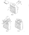
Fig 1 is a expanded perspective view of an embodiment to the present invention shown in conjunction with a standard amplifier and signal processor -
Figs. 1B and 1C are perspective views of a suggested way of removably attaching the bracket device of the present invention to a standard amplifier -
Fig 2 is a perspective view of the present invention in use after having carried out the application steps ofFigs 1B and 1C -
Figs 3A and 3B are perspective views oftwo versions of the bracket device of the present invention -
Fig 4 is a perspective view showing the bracket device offig 3B in use atop a standard amplifier for supporting multiple devices thereupon - Novel features which are characteristic of the invention, as to organization and method of operation, together with further objects and advantages thereof will be better understood from the following description considered in connection with the accompanying drawings, in which preferred embodiments of the invention are illustrated by way of example. It is to be expressly understood, however, that the drawings are for illustration description only and are not intended as definitions of the limits of the invention The various features of novelty which characterize the invention are recite with particularity in the claims
- There has been broadly outlined more important features of the invention in the summary above and in order that the detailed description which follows may be better understood, and in order that the present contribution to the art may be appreciated There are, of course, additional features of the invention that will be described hereinafter and which will form additional subject matter of the claims appended hereto. Those skilled in the art will appreciate that the conception upon which this disclosure is based readily may be utilized as a basis for the designing of other structures, methods and systems for carrying out the several purposes of the present invention. It is important therefore, that claims be regarded as including such equivalent constructions insofar as they do not depart from the spirit and scope of the present invention
- Certain terminology and the derivations thereof may be used in the following description for convenience and reference only, and will not be limiting. For example, words such as "upward," "dawnward," "left," and "right" refer to directions in the drawings to which reference is made unless otherwise stated Similar words such as "inward" and "outward" refer to directions toward and away from, respectively, the geometric center of a device or area and designated parts thereof Reference in the singular tense include the plural and vice versa, unless otherwise noted.
- Turning first to
Fig. 1A ,amplifier 11 is depictedBracket device 10 is also shown and, referring toFig. 3A , is composed of subparts, namely, U-shapedtop portion 22, a pair ofbridging members top portion 22 and a pair ofextension members bridging members distal ends 28 and 29 which, in its preferred embodiment, are curved and sized to drape overtop 17 ofamplifier 11 as shown inFig 1C -
Bracket device 10 in its relaxed state (Figs. 3A and 3B ) is sized such thatextension members hardware Fig 1B , the thumb and index finger ofappendages 52 can causedistal ends 28 and 29 of' extension members handle 20 facilitated bylifting handle 20 in the direction ofarrow 54 by appended 51. Having done so, because of the elastic modulus ofbracket device 10,extension members hardware arrows 57 and 58 With this frictional pressure placed upon the securing hardware, together with the securing ofhandle 20 and the overlapping lip established by the curved portion at the extremity ofextension members bracket device 10 cannot inadvertently be dislodged from its joined position as best seen in reference toFig 1C - Once
bracket device 10 has been joined to amplifier 11, an auxiliary device, such ascontrol box 21, can be inserted as shown inFig. 2 . In that controllers, such as that depicted herein are intended to be rack mounted and are thus of a generally standard dimension, a suitable spacing can be established between U-shapedtop portion 22 andextension members amplifier 11 was to be inadvertently bumped to the point wherebase 12 was no longer residing on a supporting surface,control box 21 would remain as shown inFig 2 Thus, damage tocontrol box 21 which would otherwise be experienced by simply laying it about a performing stage or loosely atop an amplifier would be completely avoided In addition, the look of the performing presentation would be much neater and more professionally staged by securely affixing the control box above or proximate to the amplifier to which it is to be interfaced - In turning to
Fig 3B , a further iteration of the present invention is presented In this instance, bridgingmembers lip 34 adjacent thereto At the extreme end of U-shapedtop portion 31 islip segment 32 resulting in the creation of a trough This trough can be employed to support auxiliary equipment shown, for example, inFig 4 ascomputer 40. In using the embodiment ofFig 3B , the remaining elements operate as described with reference to the embodiment ofFig. 3A includingextension members 3 and 36 with lips at distal ends 3 7 and 38 residing atopamplifier 11 - Although
bracket devices distal ends 28/29 and 37/38 Ideally, the constructs can be created by bending steel wire into shape from a 110 cm piece pre-coated with PVC In addition to dipping, PVC tubing can be heated and slipped over the stainless steel wire stock to complete the device - The above disclosure is sufficient to enable one of ordinary skill in the art to practice the invention, and provides the best mode of practicing the invention presently contemplated by the inventor While there is provided herein a full and complete disclosure of the preferred embodiments of the invention, it is not desired to limit the invention to the exact construction, dimensions, relationships, or operations as described Various modifications, alternative constructions, changes and equivalents will readily occur to those skilled in the art and may be employed as suitable without departing from the true spirit and scope of the invention Such changes might involve alternative materials, components, structural arrangements, sizes, shapes, forms, functions, operational features or the like.
- Therefore, the above description and illustration should not be considered as limiting the scope of'the invention, which is defined by the appended claims
Claims (12)
- A bracket device for removably securing a device such as a control box atop a portable amplifier, said portable amplifier having a front, back, sides and a top, a handle secured to said top by spaced apart securing hardware, said handle being of a length to enable a user to grasp it between said securing hardware, said bracket device comprising a resilient construct having a U-shaped top portion, a pair of bridging members emanating from said U-shaped top portion and a pair of extension members extending substantially perpendicularly from said bridging members and having free distal ends, said extension members being spaced from one another approximately the distance between said spaced apart securing hardware, said bracket device being sufficiently resilient to enable said extension members to be drawn together a sufficient distance to enable said free distal ends to pass between said securing hardware and beneath said handle and to exert lateral pressure against said securing hardware to resist inadvertent removal of said bracket device from atop said amplifier.
- In combination, a bracket device for securing a device such as a control box atop a portable amplifier and an amplifier for receiving said securing device, said portable amplifier having a front, back, sides and a top, a handle secured to said top by spaced apart securing hardware, said handle being of a length to enable a user to grasp it between said securing hardware, said bracket device comprising a resilient construct having a U-shaped top portion, a pair of bridging members emanating from said U-shaped top portion and a pair of extension members extending substantially perpendicularly from said bridging members and having free distal ends, said extension members being spaced from one another approximately the distance between said spaced apart securing hardware, said bracket device being sufficiently resilient to enable said extension members to be drawn together a sufficient distance to enable said free distal ends to pass between said securing hardware and beneath said handle and to exert lateral pressure against said securing hardware to resist inadvertent removal of said bracket device from atop said amplifier.
- The bracket device of claim 1 or the combination of claim 2 wherein said distal ends of said extension members are provided with curved segment sized to drape over said top when said bracket device is positioned on said amplifier.
- The bracket device of claim 1 or claim 3 or the combination of claim 2 or claim 3 wherein said bridging members are of a length to receive and to frictionally and removably secure said control box between said U-shaped portion and said extension members.
- The bracket device of claim 1 or of any preceding claim, or the combination of claim 2 or of any preceding claim, wherein said resilient construct comprises a length of wire.
- The bracket device of claim 5, or the combination of claim 5 wherein said length of wire comprises 5 mm stainless steel wire.
- The bracket device or combination of claim 5 wherein said length of wire comprises 8 mm stainless wire.
- The bracket device of claim 5 or claim 6, or claim 7 or the combination of claim 5 or claim 6 or claim 7 wherein said length of wire is coated with a layer of PVC.
- The bracket device of claim 1 or of any preceding claim, or the combination of claim 2 or of any preceding claim, wherein said resilient construct comprises a length of poly tube.
- The bracket of claim 1 or of any preceding claim, or the combination of claim 2 or of any preceding claim, wherein said U-shaped portion further comprises lip segments for receiving hardware items atop said bracket device when positioned atop of said amplifier.
- A method for removably securing a device such as a control box atop a portable amplifier, said portable amplifier having a front, back, sides and top, a handle secured to said top by spaced apart securing hardware, said handle being of a length to enable a user to grasp it between said securing hardware, said bracket device comprising a resilient construct having a U-shaped top portion, a pair of bridging members emanating from said U-shaped top portion and a pair of extension members extending substantially perpendicularly from said bridging members and having free distal ends, said extension members being spaced from one another approximately the distance between said spaced apart securing hardware, said bracket device being sufficiently resilient to enable said extension members to be drawn together a sufficient distance to enable said free distal ends to pass between said securing hardware and beneath said handle and to exert lateral pressure against said securing hardware to resist inadvertent removal of said bracket device from atop said amplifier, wherein said extension members are drawn together at their distal ends and said distal ends inserted atop said amplifier and beneath said handle to clear said securing hardware whereupon said distal ends are released causing them to separate from one another at their distal ends creating frictional pressure against said securing hardware whereupon said device such as a control box is inserted between said U-shaped top portion and pair of extension members.
- The method of claim 11 wherein said distal ends of said extension members are provided with curved segments sized to drape over said top when said bracket device is positioned on said amplifier, said extension members being inserted beneath said handles a sufficient distance to enable said curved segments to extend over said top against the front of said amplifier.
Applications Claiming Priority (2)
| Application Number | Priority Date | Filing Date | Title |
|---|---|---|---|
| US28485109P | 2009-12-28 | 2009-12-28 | |
| US12/763,393 US8181922B2 (en) | 2009-12-28 | 2010-04-20 | Amplifier affixed bracket securing device |
Publications (2)
| Publication Number | Publication Date |
|---|---|
| EP2339865A2 true EP2339865A2 (en) | 2011-06-29 |
| EP2339865A3 EP2339865A3 (en) | 2013-01-09 |
Family
ID=43802820
Family Applications (1)
| Application Number | Title | Priority Date | Filing Date |
|---|---|---|---|
| EP10189436A Withdrawn EP2339865A3 (en) | 2009-12-28 | 2010-10-29 | Bracket device |
Country Status (5)
| Country | Link |
|---|---|
| US (1) | US8181922B2 (en) |
| EP (1) | EP2339865A3 (en) |
| JP (1) | JP2011155246A (en) |
| KR (1) | KR20110076767A (en) |
| CN (1) | CN102109083A (en) |
Families Citing this family (8)
| Publication number | Priority date | Publication date | Assignee | Title |
|---|---|---|---|---|
| US8556090B2 (en) * | 2011-10-18 | 2013-10-15 | Fang-Yin Chen | Storage rack |
| US20140151316A1 (en) * | 2012-12-04 | 2014-06-05 | Therese BEACH | Display device |
| USD924202S1 (en) * | 2018-11-29 | 2021-07-06 | Lg Electronics Inc. | Audio player |
| USD924843S1 (en) * | 2018-11-29 | 2021-07-13 | Lg Electronics Inc. | Audio player |
| USD899853S1 (en) * | 2019-05-02 | 2020-10-27 | Spectrum Diversified Designs, Llc | Food roaster |
| US10902828B1 (en) * | 2020-04-26 | 2021-01-26 | Keith Baumbaugh | Amplifier equipment mounting system |
| USD1061228S1 (en) * | 2022-08-22 | 2025-02-11 | Hubbell Incorporated | Electrical component hanger |
| USD1067761S1 (en) | 2022-08-22 | 2025-03-25 | Hubbell Incorporated | Electrical component hanger |
Family Cites Families (24)
| Publication number | Priority date | Publication date | Assignee | Title |
|---|---|---|---|---|
| US418420A (en) * | 1889-12-31 | Barrel-head holder | ||
| US926798A (en) * | 1909-02-06 | 1909-07-06 | Frank Harrison Wilson | Sewing or work basket holder. |
| US1858836A (en) * | 1930-03-14 | 1932-05-17 | S M Siesel Co | Structural steel wrapping spacer |
| US2216876A (en) * | 1938-02-12 | 1940-10-08 | Crum Emma Wylly | Supporting device |
| US2253847A (en) * | 1939-06-15 | 1941-08-26 | Crum Emma Wylly | Bell cord and receptacle holder |
| US2350600A (en) * | 1943-09-21 | 1944-06-06 | Charles E Foster | Safety fluorescent lamp clip |
| US2461374A (en) * | 1944-10-13 | 1949-02-08 | Harry W Custer | Receptacle supporting rack |
| US2658116A (en) * | 1951-02-15 | 1953-11-03 | Vincent J Skantze | Telephone handset holder |
| US3220434A (en) * | 1964-12-23 | 1965-11-30 | Andrew B Young | Bedside hanger and surgical bag |
| US3532225A (en) * | 1968-03-21 | 1970-10-06 | Maude F Reed | Convertible geometric structure |
| US3765633A (en) * | 1971-06-17 | 1973-10-16 | Littiken D | Musical instrument stand |
| US4775124A (en) * | 1987-07-23 | 1988-10-04 | Hicks Donald D | Suspension soap holder |
| US4991809A (en) * | 1989-11-13 | 1991-02-12 | Harkey James R | Musical instrument support |
| US5042761A (en) * | 1990-03-30 | 1991-08-27 | Mcbride Donald J | Keyboard bracket |
| US5016847A (en) * | 1990-05-15 | 1991-05-21 | Herzig Paul A | Object retaining apparatus for a vehicle |
| US5313866A (en) * | 1992-10-30 | 1994-05-24 | Guitar & Light Fabrication | Guitar stand |
| US5556068A (en) * | 1994-10-17 | 1996-09-17 | Gorelik; Yakov | Pegboard article holder |
| US6045107A (en) * | 1998-12-09 | 2000-04-04 | Carlson; Terry A. | Holder for reading material |
| US6720490B1 (en) * | 2002-05-14 | 2004-04-13 | Harper M. Bruce | Adjustable musician's stand |
| CN2557433Y (en) * | 2002-07-31 | 2003-06-25 | 宾朝晖 | Multi-specification item bag support frame |
| DE20321020U1 (en) * | 2003-03-01 | 2005-10-13 | Schmiddem, Jochen | Holder for holding e.g. paint brush relative to paint bucket, has support formed at one end of brush handle to hold handle while brush body is supported on brim of paint bucket such that holder is clamped to bucket by clamp |
| US7318567B2 (en) * | 2005-03-07 | 2008-01-15 | Belkin International, Inc. | Cable management device |
| ITTO20060071U1 (en) * | 2006-05-17 | 2007-11-18 | Luca Cianfriglia | GUITAR-HOLDER, OR OTHER ROPE INSTRUMENTS (LOW, VIOLIN, VIOLONCELLO, BASS-BOX, ETC.) IN CARDBOARD, OR OTHER MATERIALS, WHICH CAN BE RECOVERED AND TRANSPORTED, TOGETHER WITH THE INSTRUMENT, IN ANY KIND OF HOUSING. |
| US7446249B2 (en) * | 2006-08-01 | 2008-11-04 | Joan Driscoll | Support for musical instrument |
-
2010
- 2010-04-20 US US12/763,393 patent/US8181922B2/en not_active Expired - Fee Related
- 2010-10-29 EP EP10189436A patent/EP2339865A3/en not_active Withdrawn
- 2010-11-17 JP JP2010257009A patent/JP2011155246A/en not_active Withdrawn
- 2010-12-13 KR KR1020100126770A patent/KR20110076767A/en not_active Withdrawn
- 2010-12-28 CN CN201010621587XA patent/CN102109083A/en active Pending
Non-Patent Citations (1)
| Title |
|---|
| None |
Also Published As
| Publication number | Publication date |
|---|---|
| US8181922B2 (en) | 2012-05-22 |
| US20110155877A1 (en) | 2011-06-30 |
| KR20110076767A (en) | 2011-07-06 |
| JP2011155246A (en) | 2011-08-11 |
| CN102109083A (en) | 2011-06-29 |
| EP2339865A3 (en) | 2013-01-09 |
Similar Documents
| Publication | Publication Date | Title |
|---|---|---|
| US8181922B2 (en) | Amplifier affixed bracket securing device | |
| US8162156B1 (en) | Implement holder and methods of use | |
| US8487169B2 (en) | Adjustable item holder | |
| US7446249B2 (en) | Support for musical instrument | |
| US8528796B1 (en) | Sock donning appliance | |
| US20210341097A1 (en) | Adaptor for portable electronic devices | |
| US11464327B2 (en) | Media article support device | |
| US8716581B1 (en) | Stringed musical instrument pick holder | |
| US4501403A (en) | Sheet music tray for a guitar | |
| US11125380B2 (en) | Multi-remote control holder device | |
| WO2003042970A1 (en) | A support for a musical instrument | |
| US20150164137A1 (en) | Tobacco Product Holder | |
| US8121332B2 (en) | Microphone mount for a cabinet | |
| US20200402485A1 (en) | Musical Instrument Retainer | |
| US20150048220A1 (en) | Cable Clip | |
| US20160163293A1 (en) | Soundhole Cover Accessories | |
| US9135900B2 (en) | Holder for musical instruments and/or accessories | |
| US7615698B2 (en) | Vibarato trainer | |
| US20170316764A1 (en) | Stick-on guitar stand | |
| US8802948B2 (en) | Guitar slide holding system and apparatus | |
| US7947886B2 (en) | Guitar slide holder | |
| US9987837B2 (en) | Adhesive film remover | |
| KR101845980B1 (en) | Thumb rest cushion | |
| US9767776B2 (en) | Support stand for a musical instrument | |
| US20160163292A1 (en) | Accessories for Instruments with Soundholes |
Legal Events
| Date | Code | Title | Description |
|---|---|---|---|
| PUAI | Public reference made under article 153(3) epc to a published international application that has entered the european phase |
Free format text: ORIGINAL CODE: 0009012 |
|
| AK | Designated contracting states |
Kind code of ref document: A2 Designated state(s): AL AT BE BG CH CY CZ DE DK EE ES FI FR GB GR HR HU IE IS IT LI LT LU LV MC MK MT NL NO PL PT RO RS SE SI SK SM TR |
|
| AX | Request for extension of the european patent |
Extension state: BA ME |
|
| PUAL | Search report despatched |
Free format text: ORIGINAL CODE: 0009013 |
|
| AK | Designated contracting states |
Kind code of ref document: A3 Designated state(s): AL AT BE BG CH CY CZ DE DK EE ES FI FR GB GR HR HU IE IS IT LI LT LU LV MC MK MT NL NO PL PT RO RS SE SI SK SM TR |
|
| AX | Request for extension of the european patent |
Extension state: BA ME |
|
| RIC1 | Information provided on ipc code assigned before grant |
Ipc: A47B 13/02 20060101ALI20121203BHEP Ipc: G10G 5/00 20060101ALI20121203BHEP Ipc: H04R 1/02 20060101AFI20121203BHEP Ipc: F16M 13/00 20060101ALI20121203BHEP |
|
| STAA | Information on the status of an ep patent application or granted ep patent |
Free format text: STATUS: THE APPLICATION IS DEEMED TO BE WITHDRAWN |
|
| 18D | Application deemed to be withdrawn |
Effective date: 20130503 |