EP2339661B1 - Electrical storage device - Google Patents
Electrical storage device Download PDFInfo
- Publication number
- EP2339661B1 EP2339661B1 EP10182425.8A EP10182425A EP2339661B1 EP 2339661 B1 EP2339661 B1 EP 2339661B1 EP 10182425 A EP10182425 A EP 10182425A EP 2339661 B1 EP2339661 B1 EP 2339661B1
- Authority
- EP
- European Patent Office
- Prior art keywords
- battery
- electrical storage
- casing
- storage device
- lithium ion
- Prior art date
- Legal status (The legal status is an assumption and is not a legal conclusion. Google has not performed a legal analysis and makes no representation as to the accuracy of the status listed.)
- Active
Links
- 239000004411 aluminium Substances 0.000 claims description 8
- 229910052782 aluminium Inorganic materials 0.000 claims description 8
- XAGFODPZIPBFFR-UHFFFAOYSA-N aluminium Chemical compound [Al] XAGFODPZIPBFFR-UHFFFAOYSA-N 0.000 claims description 8
- 230000000712 assembly Effects 0.000 claims description 4
- 238000000429 assembly Methods 0.000 claims description 4
- HBBGRARXTFLTSG-UHFFFAOYSA-N Lithium ion Chemical compound [Li+] HBBGRARXTFLTSG-UHFFFAOYSA-N 0.000 description 94
- 229910001416 lithium ion Inorganic materials 0.000 description 94
- 239000002826 coolant Substances 0.000 description 40
- 239000003990 capacitor Substances 0.000 description 14
- 238000006243 chemical reaction Methods 0.000 description 12
- 239000004065 semiconductor Substances 0.000 description 12
- 230000005856 abnormality Effects 0.000 description 8
- 238000009499 grossing Methods 0.000 description 8
- 238000004891 communication Methods 0.000 description 7
- 238000001816 cooling Methods 0.000 description 7
- 238000001514 detection method Methods 0.000 description 7
- 238000005259 measurement Methods 0.000 description 7
- 239000004020 conductor Substances 0.000 description 6
- 238000004804 winding Methods 0.000 description 6
- 238000007789 sealing Methods 0.000 description 5
- 229910000831 Steel Inorganic materials 0.000 description 4
- 239000008151 electrolyte solution Substances 0.000 description 4
- 229910052751 metal Inorganic materials 0.000 description 4
- 239000002184 metal Substances 0.000 description 4
- 238000012545 processing Methods 0.000 description 4
- 239000010959 steel Substances 0.000 description 4
- 238000002485 combustion reaction Methods 0.000 description 3
- 230000006378 damage Effects 0.000 description 3
- CURLTUGMZLYLDI-UHFFFAOYSA-N Carbon dioxide Chemical compound O=C=O CURLTUGMZLYLDI-UHFFFAOYSA-N 0.000 description 2
- 238000003491 array Methods 0.000 description 2
- 230000005540 biological transmission Effects 0.000 description 2
- 239000012530 fluid Substances 0.000 description 2
- 230000004907 flux Effects 0.000 description 2
- 238000007689 inspection Methods 0.000 description 2
- 239000000696 magnetic material Substances 0.000 description 2
- 238000012423 maintenance Methods 0.000 description 2
- 229910052987 metal hydride Inorganic materials 0.000 description 2
- 239000003595 mist Substances 0.000 description 2
- 238000010248 power generation Methods 0.000 description 2
- 239000011347 resin Substances 0.000 description 2
- 229920005989 resin Polymers 0.000 description 2
- RYGMFSIKBFXOCR-UHFFFAOYSA-N Copper Chemical compound [Cu] RYGMFSIKBFXOCR-UHFFFAOYSA-N 0.000 description 1
- 239000002253 acid Substances 0.000 description 1
- OJIJEKBXJYRIBZ-UHFFFAOYSA-N cadmium nickel Chemical compound [Ni].[Cd] OJIJEKBXJYRIBZ-UHFFFAOYSA-N 0.000 description 1
- 229910002092 carbon dioxide Inorganic materials 0.000 description 1
- 239000001569 carbon dioxide Substances 0.000 description 1
- 238000011109 contamination Methods 0.000 description 1
- 229910052802 copper Inorganic materials 0.000 description 1
- 239000010949 copper Substances 0.000 description 1
- 230000006837 decompression Effects 0.000 description 1
- 238000013461 design Methods 0.000 description 1
- 238000003745 diagnosis Methods 0.000 description 1
- 238000010586 diagram Methods 0.000 description 1
- 230000000694 effects Effects 0.000 description 1
- 238000010292 electrical insulation Methods 0.000 description 1
- 238000004070 electrodeposition Methods 0.000 description 1
- 230000005669 field effect Effects 0.000 description 1
- 230000006698 induction Effects 0.000 description 1
- 238000009434 installation Methods 0.000 description 1
- 239000007788 liquid Substances 0.000 description 1
- 239000000463 material Substances 0.000 description 1
- 229910044991 metal oxide Inorganic materials 0.000 description 1
- 150000004706 metal oxides Chemical class 0.000 description 1
- 239000000203 mixture Substances 0.000 description 1
- 238000000465 moulding Methods 0.000 description 1
- 230000003071 parasitic effect Effects 0.000 description 1
- 230000008929 regeneration Effects 0.000 description 1
- 238000011069 regeneration method Methods 0.000 description 1
- 230000001105 regulatory effect Effects 0.000 description 1
- 238000007493 shaping process Methods 0.000 description 1
- 230000001360 synchronised effect Effects 0.000 description 1
Images


Classifications
-
- H—ELECTRICITY
- H01—ELECTRIC ELEMENTS
- H01M—PROCESSES OR MEANS, e.g. BATTERIES, FOR THE DIRECT CONVERSION OF CHEMICAL ENERGY INTO ELECTRICAL ENERGY
- H01M10/00—Secondary cells; Manufacture thereof
- H01M10/42—Methods or arrangements for servicing or maintenance of secondary cells or secondary half-cells
- H01M10/48—Accumulators combined with arrangements for measuring, testing or indicating the condition of cells, e.g. the level or density of the electrolyte
-
- H—ELECTRICITY
- H01—ELECTRIC ELEMENTS
- H01M—PROCESSES OR MEANS, e.g. BATTERIES, FOR THE DIRECT CONVERSION OF CHEMICAL ENERGY INTO ELECTRICAL ENERGY
- H01M10/00—Secondary cells; Manufacture thereof
- H01M10/42—Methods or arrangements for servicing or maintenance of secondary cells or secondary half-cells
- H01M10/425—Structural combination with electronic components, e.g. electronic circuits integrated to the outside of the casing
-
- Y—GENERAL TAGGING OF NEW TECHNOLOGICAL DEVELOPMENTS; GENERAL TAGGING OF CROSS-SECTIONAL TECHNOLOGIES SPANNING OVER SEVERAL SECTIONS OF THE IPC; TECHNICAL SUBJECTS COVERED BY FORMER USPC CROSS-REFERENCE ART COLLECTIONS [XRACs] AND DIGESTS
- Y02—TECHNOLOGIES OR APPLICATIONS FOR MITIGATION OR ADAPTATION AGAINST CLIMATE CHANGE
- Y02E—REDUCTION OF GREENHOUSE GAS [GHG] EMISSIONS, RELATED TO ENERGY GENERATION, TRANSMISSION OR DISTRIBUTION
- Y02E60/00—Enabling technologies; Technologies with a potential or indirect contribution to GHG emissions mitigation
- Y02E60/10—Energy storage using batteries
Definitions
- the present invention relates to an electrical storage device that includes a battery module with a plurality of battery cells housed in a battery house casing and a management circuit thereof.
- Electric vehicles that use a rotating electric machine as a driving source and hybrid vehicles that use both an internal combustion engine and a rotating electric machine have recently been put to practical use.
- Those types of vehicles are mounted with a battery that supplies electrical energy to the rotating electric machine, and such battery to be mounted includes rechargeable secondary batteries such as a nickel-cadmium battery, a nickel-metal hydride battery, and a lithium ion battery.
- a secondary battery is usually constituted as a battery module with a plurality of battery cells placed on top of one another, the bottom surface of a battery house casing is attached to the vehicle body through a module base, and a battery controller is mounted in the neighborhood thereof such as the top surface of the battery house casing or a side surface to manage the state of electrical storage, as disclosed in Japanese Laid Open Patent Publication No. 2004-319304 .
- an on-vehicle battery and electric unit assembly including a battery mounted to a body of a vehicle driven by an engine and an electric unit in which components of an electrical circuit connected to the battery are housed in a unit case provided with a positive DC terminal and a negative DC terminal connected to a positive terminal and a negative terminal of the battery are known, wherein the electric unit is placed adjacent to the battery, and the positive terminal and the negative terminal of the battery are connected to the positive DC terminal and the negative DC terminal of the electric unit by a positive busbar and a negative busbar, respectively.
- a battery controller includes a built-in electric circuit, which needs to be grounded for its normal operation, and therefore the battery controller and the module base are often connected through a thick ground wire.
- the invention provides an electrical storage device having the features of claim 1.
- An electrical storage device comprises: a conductive battery house casing electrically connected to a chassis; a plurality of battery cells held in the battery house casing; and/or a control unit that comprises a circuit that manages the plurality of battery cells and is mounted on the battery house casing so that a negative terminal of the circuit and the battery house casing are electrically conducting.
- the electrical storage device according to the first aspect further comprises a mounting member that electrically connects and fixes the battery house casing to the chassis.
- the battery house casing may comprise: a conductive lower base; a conductive upper base that is connected to the lower base from above to form a casing body circularly formed with both side surfaces being open; and side plates that hold the battery cells while closing the both side surfaces of the casing body.
- the battery house casing may comprise a circular member with both side surfaces being open; and side plates that hold the battery cells while closing the both side surfaces of the circular member.
- the electrical storage device may further comprise a mounting member that electrically connects and fixes the battery house casing to the chassis.
- the electrical storage device may further comprise a plurality of the battery house casings in which a battery assembly constituted with the plurality of battery cells is housed, wherein: the control unit may be mounted astride a top surface of the plurality of battery house casings.
- the battery house casing may be formed from die-cast aluminium.
- An electric powered vehicle comprises: a travel drive device that generates travel drive on electric power; an electrical storage device according to the fourth to seventh aspects that generates the electric power; and a vehicle body on which the travel drive device is provided, wherein: the battery house casing is mounted on the vehicle body through a mounting member so that the vehicle body is set to ground potential.
- An electrical storage device comprises: a first and second conductive battery house casings being juxtaposed; a first and second battery assemblies, each of which is constituted with a plurality of battery cells, that are held in the first and second battery house casings, respectively; and a control unit that comprises a circuit which manages the first and second battery assemblies and that is mounted on the first and second battery house casings so that a negative terminal of the circuit and the first and second battery house casings are electrically conducting and the first and second battery house casings are integrated.
- An electric vehicle includes a hybrid electric vehicle that has both an internal combustion engine and an electric machine as a driving source of the vehicle and a pure electric vehicle that has an electric machine as an only driving source of the vehicle.
- the structure of the vehicle-mounted electric machine system (electrical machine driving system) that includes the electrical storage device according to an embodiment will now be explained with reference to FIG. 1 .
- the vehicle-mounted electric machine system includes a motor generator 10, an inverter device 20, a vehicle controller 30 that controls the whole vehicle, and an electrical storage device 1000 that constitutes a vehicle-mounted power source.
- the electrical storage device 1000 includes a plurality of storage batteries and is constituted as, for instance, a lithium ion battery device that includes a plurality of lithium ion battery cells.
- An electric powered vehicle including an electric vehicle and a hybrid vehicle, on which such vehicle-mounted electric machine system is mounted includes a travel drive device that generates travel drive on electric power, the electrical storage device according to the present invention that supplies electric power to the travel drive device, and a vehicle body that is provided with the travel drive device.
- the electrical storage device includes a battery block constituted by housing a battery assembly constituted with a plurality of battery cells into a conductive casing and a control unit that includes a battery controller and a cell controller that manage the battery cells.
- the controller in particular, in order to provide a ground path of a negative terminal of the circuit board of the battery controller and the cell controller, the controller is grounded to the vehicle body grounding only by integrating the control unit to the battery block without separately routing a conventional ground wire.
- the motor generator 10 is a three-phase alternate-current machine. Any of two types of three-phase AC machine, a synchronous machine and an induction machine, may be adopted. In operating mode requiring rotational power such as during power running of the vehicle or starting the internal combustion engine, the motor generator 10 drives the motor and supplies the generated rotational power to driven bodies such as wheels and the engine. In this case, the vehicle-mounted electric machine system converts DC (direct current) power into three-phase AC electric power and supplies it from the lithium ion battery device 1000 to the motor generator 10 via the inverter device 20, which is an electric power conversion device.
- DC direct current
- the motor generator 10 receives drive power from the wheels or the engine and works as a generator to generate three-phase AC electric power.
- the vehicle-mounted electric machine system converts the three-phase AC electric power from the motor generator 10 into DC power via the inverter device 20 and supplies it to the lithium ion battery device 1000. As a result, electric power is accumulated in the lithium ion battery device 1000.
- the motor generator 10 is an electric machine that is operated by a magnetic influence of an armature, for example, a stator and a field, for example, a rotor, that is disposed opposite the armature and rotatably supported.
- the motor generator 10 assumes a structure that allows the axis of rotation of the field to be mechanically connected to the axis of rotation of the driven bodies such as the wheels and the engine so that rotational power can be directed to and from the driven bodies.
- the armature is a part that is to be supplied with three-phase AC electric power to generate a rotating magnetic field when the motor generator 10 is engaged in operation as a motor or as a generator.
- the armature includes an armature core, that is, a stator core, which is a magnetic material, and a three-phase armature winding, that is, a stator winding, attached to the armature core.
- the field is a part that generates field magnetic flux when the motor generator 10 is engaged in operation as a motor or a generator.
- the field includes a field core, that is, a rotor core, which is a magnetic material, and a permanent magnet, a field winding, that is, a rotor winding, or conductor bar, that are attached to the field core, or the field core and both a permanent magnet and a field winding (or a conductor bar).
- the field winding generates magnetic flux by being excited with field current supplied from an external power source.
- the inverter device 20 is an electronic circuit device that controls the power conversion described above, i.e., the conversion from DC power to three-phase AC electric power and from three-phase AC electric power to DC power, by operation (ON/OFF) of a switching semiconductor device.
- the inverter device 20 includes a power module 21, a driver circuit 22, a motor controller 23, and a smoothing capacitor 24.
- the power module 21 is a power conversion circuit that includes six switching semiconductor devices to perform the power conversion described above by switching operation (ON/OFF) of the six switching semiconductor devices.
- a metal-oxide semiconductor field-effect transistor (MOSFET) or an insulated gate bipolar transistor (IGBT) is used for the switching semiconductor devices.
- MOSFET metal-oxide semiconductor field-effect transistor
- IGBT insulated gate bipolar transistor
- parasitic diodes are electrically connected in inverse parallel between a drain electrode and a source electrode.
- IGBT insulated gate bipolar transistor
- the power conversion circuit is constituted with a three-phase bridge circuit, in which series circuits (an arm for one phase), each of which includes two (an upper arm and a lower arm) switching semiconductor devices electrically connected in series, are electrically connected in parallel for three phases.
- each upper arm opposite the lower arm connection side is electrically connected to a DC positive pole-side module terminal
- the side of each lower arm opposite the upper arm connection side is electrically connected to a DC negative pole-side module terminal.
- the middle point of each of the upper and the lower arms i.e., the sides of each of the upper and the lower arms connecting to each other, are electrically connected to an AC-side module terminal.
- the DC positive pole-side module terminal and the DC negative pole-side module terminal are electrically connected to a DC positive pole-side external terminal and a DC negative pole-side external terminal, respectively.
- the DC positive pole-side external terminal and the DC negative pole-side external terminal are power source-side terminals to direct DC power to and from the lithium ion battery device 1000 and electrically connected with a power cable 600 that extends from the lithium ion battery device 1000.
- the AC-side module terminal is electrically connected to an AC-side external terminal.
- the AC-side external terminal is a load side terminal to direct three-phase AC electric power to and from the motor generator 10 and electrically connected with a load cable that extends from the motor generator 10.
- the smoothing capacitor 24 is electrically connected in parallel between the DC positive pole-side and the DC negative pole-side of the power conversion circuit in order to inhibit a voltage fluctuation that arises from a high speed switching operation of the switching semiconductor devices constituting the power conversion circuit.
- the motor controller 23 is an electronic circuit device to control the switching operation of the six switching semiconductor devices constituting the power conversion circuit. Based upon a torque command having been output from the vehicle controller 30 that controls a higher-order control unit, for instance the whole vehicle, the motor controller 23 generates a switching operation command signal, for example, PWM (pulse width modulation) signal, to the six switching semiconductor devices. The generated command signal is output to the driver circuit 22.
- a switching operation command signal for example, PWM (pulse width modulation) signal
- the driver circuit 22 Based upon the switching operation command signal having been output from the motor controller 23, the driver circuit 22 generates a drive signal to the six switching semiconductor devices constituting the power conversion circuit.
- the generated drive signal is output to a gate electrode of the six switching semiconductor devices constituting the power conversion circuit.
- switching (ON/OFF) of the six switching semiconductor devices constituting the power conversion circuit is controlled based upon the drive signal having been output from the driver circuit 22.
- the lithium ion battery device 1000 includes a battery module 100 to accumulate and release electrical energy, i.e., to charge and discharge DC power, and a control unit 900 to manage and control the state of the battery module 100 (refer to FIG. 2 ).
- the battery module 100 is constituted with two battery blocks or battery packs, i.e., a higher potential battery block 100a and a lower potential battery block 100b that are electrically connected in series.
- a battery assembly is housed in each of the battery blocks.
- Each of the battery assemblies is constituted with a combination of a plurality of lithium ion battery cells that are electrically connected in series. The structure of each of the battery blocks will be described later.
- An SD (service disconnect) switch 700 is provided between the negative pole-side, or lower potential side, of the higher potential battery block 100a and the positive pole-side, or higher potential side, of the lower potential battery block 100b.
- the SD switch 700 a safety device provided to ensure the safety at maintenance and inspection of the lithium ion battery device 1000, is constituted with an electrical circuit in which a switch and a fuse are electrically connected in series, and to be operated by a serviceman at the time of maintenance and inspection.
- the control unit 900 is constituted with a higher-order (parent) battery controller 300 and a lower-order (child) cell controller 200.
- the control unit 900 is constituted by mounting the control board of the battery controller 300 and the control board of the cell controller 200 onto a board mount surface of a base 910 formed of a conductive material. When those control boards are mounted, the negative terminal of each of the control boards of the battery controller 300 and the cell controller 200 is electrically connected to the base 910. It is to be noted that in the interests of brevity, grounding of the battery controller 300 and the cell controller 200 will be hereinafter explained as a synonym of connection of the negative terminal of each of the control boards to the vehicle body grounding potential.
- the higher potential battery block 100a and the lower potential battery block 100b are juxtaposed, and the control unit 900 is disposed astride their top surfaces.
- the control unit 900 and the base 910 are mounted to the blocks 100a and 100b so as to integrate both of the blocks 100a and 100b.
- the battery blocks 100a and 100b are constituted by housing a plurality of battery cells in a conductive casing 110.
- the casing 110 is then electrically and mechanically connected to the vehicle body through a conductive module base 101.
- the potential at the negative terminals of the battery controller 300 and the cell controller 200 hence becomes equal to the ground potential at the vehicle body through the casing 110.
- a ground wire through which the battery controller 300 and the cell controller 200 are grounded to the vehicle body is not required.
- the battery controller 300 manages and controls the state of the lithium ion battery device 1000 and notifies the vehicle controller 30 and the motor controller 23, which are higher-order control units, of the state of the lithium ion battery device 1000 and a charge/discharge control command to control allowable charge/discharge electric power and the like.
- the management and control of the state of the lithium ion battery device 1000 include measurement of the voltage and current at the lithium ion battery device 1000, arithmetic operations of the state of charge (SOC), the state of health (SOH), and the like at the lithium ion battery device 1000, measurement of temperature at each of the battery blocks, output of a command to the cell controller 200 (for example, a command to measure the voltage at each of the lithium ion battery cells, a command to adjust the stored charge at each of the lithium ion battery cells, and the like), and the like.
- SOC state of charge
- SOH state of health
- the cell controller 200 is a so-called hand and foot of the battery controller 300, which, according to a command from the battery controller 300, manages and controls the state of the plurality of lithium ion battery cells and is constituted with a plurality of integrated circuits (IC).
- the management and control of the state of the plurality of lithium ion battery cells include measurement of the voltage at each of the lithium ion battery cells, adjustment of the stored charge at each of the lithium ion battery cells, and the like.
- Each of the integrated circuits is designated to a plurality of corresponding lithium ion battery cells, and manages and controls the state of the plurality of corresponding lithium ion battery cells.
- the power source of the battery controller 300 uses a battery for auxiliaries, in case of an automobile, a lead acid battery with a nominal output voltage of 12V, that is mounted as a power source for vehicle-mounted auxiliaries, for instance, lights and audio equipment. For this reason, voltage (12V for instance) is applied from the battery for auxiliaries to the battery controller 300.
- the battery controller 300 steps down (steps down to 5V for example) the applied voltage via a power source circuit constituted with a DC-DC power converter and applies the stepped down voltage to electronic components that constitute the battery controller 300 as a drive voltage. As a result, the electronic components that constitute the battery controller 300 are actuated.
- the plurality of corresponding lithium ion battery cells are used as a power source of the integrated circuits that constitute the cell controller 200. For this reason, the cell controller 200 and the battery module 100 are electrically connected with each other through a connecting wire 800. Voltage of the highest potential at the plurality of corresponding lithium ion battery cells is applied to each of the integrated circuits through the connecting wire 800. Each of the integrated circuits steps down the applied voltage via the power source circuit (steps down to 5V for example) and uses it as an operational power source.
- a signal that has been output from an ignition key switch is input to the battery controller 300.
- the signal that has been output from the ignition key switch is used as a signal of start-up and shutdown of the lithium ion battery device 1000.
- the power source circuit is actuated based upon an output signal from the ignition key switch, and a drive voltage is applied from the power source circuit to a plurality of electronic circuit components so that the plurality of electronic circuit components are actuated.
- the battery controller 300 starts up as a result.
- a start-up command is output from the battery controller 300 to the cell controller 200.
- the power source circuits of the plurality of integrated circuits are actuated in sequence and the plurality of integrated circuits start up in sequence.
- the cell controller 200 starts up as a result.
- predetermined initial processing is executed so that the lithium ion battery device 1000 starts up.
- the predetermined initial processing includes, for instance, measurement of the voltage at each of the lithium ion battery cells, an abnormality diagnosis, measurement of the voltage and current at the lithium ion battery device 1000, measurement of the temperature at each of the battery blocks, arithmetic operations on the state of charge and the state of health of the lithium ion battery device 1000, arithmetic operations of the allowable charge/discharge electric power of the lithium ion battery device 1000, and the like.
- a stop command is output from the battery controller 300 to the cell controller 200.
- the cell controller 200 receives the stop command, predetermined termination processing is executed, and then the power source circuits of the plurality of integrated circuits stop in sequence and the plurality of integrated circuits stop in sequence.
- the cell controller 200 stops as a result.
- the battery controller 300 the operations of the power source circuits stop and the operations of the plurality of electronic circuit components stop.
- the battery controller 300 stops and the lithium ion battery device 1000 stops.
- the predetermined termination processing includes, for instance, measurement of the voltage at each of the lithium ion battery cells, adjustment of the stored charge at each of the lithium ion battery cells, and the like.
- In-vehicle local area network communication is used for transmission of information between the battery controller 300 and higher-order control units such as the vehicle controller 30 and the motor controller 23.
- Local interconnect network communication which conforms to the in-vehicle local area network communication, is used for transmission of information between the battery controller 300 and the cell controller 200.
- a positive terminal of the higher potential battery block 100a and the DC positive-side external terminal of the inverter device 20 are electrically connected with each other through a positive-side power cable 610.
- a negative terminal of the lower potential battery block 100b and the DC negative-side external terminal of the inverter device 20 are electrically connected with each other through a negative-side power cable 620.
- a junction box 400 is provided along the power cable 600.
- a relay mechanism constituted with a main relay 410 and a precharge circuit 420 is housed in the junction box 400.
- the relay mechanism is an open/close section to allow electrical conduction and block between the battery module 100 and the inverter device 20, more specifically, the relay mechanism allows conduction between the battery module 100 and the inverter device 20 at the start-up of the vehicle-mounted electrical machine system while it allows block between the battery module 100 and the inverter device 20 at the time of stop or in the event of an abnormality of the vehicle-mounted electrical machine system.
- the relay mechanism thus controls between the lithium ion battery device 1000 and the inverter device 20 so as to ensure a high level of safety of the vehicle-mounted electrical machine system.
- Drive of the relay mechanism is controlled by the motor controller 23.
- the motor controller 23 Upon reception of a notification of start-up completion of the lithium ion battery device 1000 from the battery controller 300, the motor controller 23 outputs a conduction command signal to the relay mechanism at the start-up of the vehicle-mounted electrical machine system so as to drive the relay mechanism.
- the motor controller 23 Upon reception of an OFF output signal from the ignition key switch at the time of stop of the vehicle-mounted electrical machine system, or upon reception of an abnormality signal from the vehicle controller 30 in the event of an abnormality of the vehicle-mounted electrical machine system, the motor controller 23 outputs a block command signal to the relay mechanism so as to drive the relay mechanism.
- the main relay 410 is constituted with a positive-side main relay 411 and a negative-side main relay 412.
- the positive-side main relay 411 is provided along the positive-side power cable 610 and controls an electrical connection between a positive-side of the lithium ion battery device 1000 and a positive-side of the inverter device 20.
- the negative-side main relay 412 is provided along the negative-side power cable 620 and controls an electrical connection between a negative-side of the lithium ion battery device 1000 and a negative-side of the inverter device 20.
- the precharge circuit 420 is a series circuit in which a precharge relay 421 and a resistor 422 are electrically connected in series, and is electrically connected in parallel to the positive-side main relay 411.
- the negative-side main relay 412 is turned on and then the precharge relay 421 is turned on.
- the current supplied from the lithium ion battery device 1000 is regulated by the resistor 422 and then is supplied to the smoothing capacitor 24 and charged.
- the positive-side main relay 411 is turned on and the precharge relay 421 is released.
- the main current is supplied from the lithium ion battery device 1000 to the inverter device 20 via the positive-side main relay 411, and the main current at this time becomes equal to or less than the allowable current at the positive-side main relay 411 and the smoothing capacitor 24.
- the smoothing capacitor 24 and the positive-side main relay 411 can be protected from a large current at the start-up of the vehicle-mounted electrical machine system without having abnormalities, such as significant heat generated at this time which may damage the smoothing capacitor 24 and the fixed and moving contacts of the positive-side main relay 411 which may become fused, caused as a large initial current flowing in momentarily from the lithium ion battery device 1000 to the inverter device 20 due to the electrical charge at the smoothing capacitor 24 being substantially zero.
- An ammeter 430 is housed inside the junction box 400.
- the ammeter 430 is provided so as to detect current supplied from the lithium ion battery device 1000 to the inverter device 20.
- An output line of the ammeter 430 is electrically connected to the battery controller 300.
- the battery controller 300 Based upon a signal that has been output from the ammeter 430, the battery controller 300 detects the current supplied from the lithium ion battery device 1000 to the inverter device 20.
- the current detection information is notified from the battery controller 300 to the motor controller 23, the vehicle controller 30, and the like.
- the ammeter 430 may be provided outside the junction box 400.
- a current detection section of the lithium ion battery device 1000 may not be just on the battery module 100 side of the positive-side main relay 411 but may also be on the inverter device 20 side of the positive-side main relay 411.
- a voltmeter to detect the voltage at the lithium ion battery device 1000 may be housed inside the junction box 400.
- An output line of the voltmeter similar to that of the ammeter 430, is electrically connected to the battery controller 300.
- the battery controller 300 Based upon an output signal from the voltmeter, the battery controller 300 detects the overall voltage at the lithium ion battery device 1000. The voltage detection information is notified to the motor controller 23 and the vehicle controller 30. It is preferable that a voltage detection section of the lithium ion battery device 1000 is positioned on both the battery module 100 side and the inverter device 20 side of the relay mechanism.
- a positive-side capacitor 500 is electrically connected between the positive-side power cable 610 and a chassis ground (assuming a potential equal to that at the vehicle chassis) of the lithium ion battery device 1000.
- a negative-side capacitor 510 is electrically connected between the negative-side power cable 620 and a chassis ground of the lithium ion battery device 1000.
- the positive-side capacitor 500 and the negative-side capacitor 510 are provided in order to prevent erroneous operation of the battery controller 300 and the cell controller 200, which are low-rate electrical circuits, and destruction of the integrated circuit (IC) constituting the cell controller 200 due to a surge voltage, by eliminating noise generated via the inverter device 20.
- the inverter device 20 includes a noise removal filter
- the positive-side capacitor 500 and the negative-side capacitor 510 are provided so as to even more effectively prevent erroneous operations of the battery controller 300 and the cell controller 200, which are low-rate electrical circuits, and destruction of the integrated circuit (IC) constituting the cell controller 200 due to a surge voltage, and improve the noise withstanding reliability of the lithium ion battery device 1000.
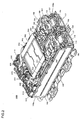
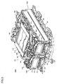
- FIGS. 2 and 3 show perspective views presenting the overall structure of the lithium ion battery device 1000.
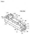
- FIG. 4 shows a perspective view of the battery block that constitutes the lithium ion battery device 1000
- FIG. 5 shows an exploded perspective view of the battery block shown in FIG. 4 .
- the lithium ion battery device 1000 is constituted with two main units of the battery module 100 and the control unit 900.
- the structure of the battery module 100 will now be explained.
- the battery module 100 is constituted with the higher potential battery block 100a and the lower potential battery block 100b, and the two battery blocks 100a and 100b are electrically connected in series. It is to be noted that the higher potential battery block 100a and the lower potential battery block 100b include exactly the same structure. FIGS. 4 and 5 therefore present only the higher potential battery block 100a as a representative example of the higher potential battery block 100a and the lower potential battery block 100b, and an explanation of the detailed structure of the lower potential battery block 100b will thus be curtailed.
- the higher potential battery block 100a and the lower potential battery block 100b are adjacently disposed in parallel with each other so that longitudinal directions of each of the blocks are in parallel.
- the higher potential battery block 100a and the lower potential battery block 100b are juxtaposed on the module base 101 and, as described later, the control unit 900 is disposed astride the top surfaces of the higher potential battery block 100a and the lower potential battery block 100b, so that both of the blocks 100a and 100b are integrated by the base 910 of the control unit 900.
- the module base 101 is constituted with a rigid, thin-wall metal plate (a steel plate for example) that is divided into three in a transverse direction and fixed to the vehicle.
- the module base 101 is constituted with three members disposed on the both ends and the middle section in the transverse direction.
- the surface of the module base 101 can be flush with the lower surface of each of the battery blocks 100a and 100b, so that the dimension of the battery module 100 in the height direction can be further reduced.
- the higher potential battery block 100a is mainly constituted with the battery house casing (hereinafter referred to as the casing) 110 and a battery assembly 120.
- the battery assembly 120 is housed and held inside the casing 110.
- the casing 110 constitutes a substantially rectangular block housing with an upper base UPB, a lower base LOB, and side plates 130 and 131.
- the casing 110 is constituted with a combination of three members.
- the upper base UPB includes an inlet channel forming plate 111, an outlet-side guide plate 113, a cooling medium inlet 114, and a cooling medium inlet duct 116 that are integrally formed from die-cast aluminium.
- the lower base LOB includes an outlet channel forming plate 118, an inlet-side guide plate 112, a cooling medium outlet 115, and a cooling medium outlet duct 117 that are integrally formed from die-cast aluminium.
- the upper base UPB and the lower base LOB are casing bodies bolted with each other at the longitudinal end portions so as to form a circular member with both of the side surfaces being open.
- the interior space of the casing 110 functions as a housing chamber in which the battery assembly 120 constituted with a plurality of battery cells 140 is housed and also functions as a cooling channel through which a cooling medium, i.e., cooling air, flows to cool down the battery assembly 120.
- a direction with the longest dimension of the casing 110 and a direction from the cooling medium inlet 114 side to the cooling medium outlet 115 side are defined as a longitudinal direction.
- a direction in which two side surfaces, i.e., the two side plates 130 and 131, different from the two side surfaces, i.e., the inlet-side guide plate 112 and the outlet-side guide plate 113, that face each other in the longitudinal direction of the casing 110, face each other, a central axial direction of the lithium ion battery cells 140 (a direction in which two electrodes of the positive terminal and the negative terminal face each other), and a direction in which a conductive member 150, which electrically connects two of the lithium ion battery cells 140, and two of the lithium ion battery cells 140 face each other are defined as a transverse direction.
- a direction in which the inlet channel forming plate 111 and the outlet channel forming plate 118 face each other is defined as a height direction regardless of the installation orientation of
- the inlet channel forming plate 111 is a rectangular flat plate that forms the top surface of the casing 110.
- the outlet channel forming plate 118 is a flat plate that forms the bottom surface of the casing 110.
- the inlet channel forming plate 111 and the outlet channel forming plate 118 are displaced with respect to each other in the longitudinal direction. As a result, the positions of the longitudinal end portions of the inlet channel forming plate 111 and the outlet channel forming plate 118 are displaced with respect to each other in the longitudinal direction.
- the inlet channel forming plate 111 i.e., the top surface of the upper base UPB is provided with a mounting section 110S with which the control unit 900 is mounted.
- a mounting section 110S is an internally threaded boss.
- the base 910 of the conductive control unit 900 on which the battery controller 300 and the cell controller 200 are to be mounted, is bolted to and in electrical communication with the mounting sections 110S of the pair of battery blocks 100a and 100b.
- the battery controller 300 and the cell controller 200 are mounted on the base 910 so that their negative terminals are in electrical communication with the base 910 of the control unit 900.
- the control unit 900 is mounted astride both the battery blocks 100a and 100b so as to juxtapose and integrate the higher potential battery block 100a and the lower potential battery block 100b.
- both the blocks 100a and 100b are integrated by mounting the control unit 900, i.e., the base 910 onto the battery blocks 100a and 100b.
- the battery blocks 100a and 100b are constituted by housing the plurality of battery cells 140 in the conductive casing 110.
- the casing 110 is then electrically and mechanically connected to the vehicle body (chassis) through the conductive module base 101.
- the potential at the negative terminals of the battery controller 300 and the cell controller 200 therefore becomes equal to the ground potential at the vehicle body through the casing 110.
- a ground wire through which the battery controller 300 and the cell controller 200 are grounded to the vehicle body is not required.
- the inlet-side guide plate 112 is a plate-like member that forms one side of the side surfaces facing the longitudinal direction of the casing 110.
- the outlet-side guide plate 113 is a plate-like member that forms the other side of the side surfaces facing the longitudinal direction of the casing 110.
- the cooling medium inlet 114 that constitutes an inlet via which cooling air, a cooling medium, is led into the casing 110 is formed between the inlet channel forming plate 111 and the inlet-side guide plate 112.
- the cooling medium inlet 114 is provided with the cooling medium inlet duct 116 to lead cooling air to the cooling medium inlet 114.
- the inlet channel forming plate 111 and the outlet channel forming plate 118 are displaced with respect to each other, and the inlet-side end of the casing 110 is formed in steps.
- a space is formed in the longitudinal direction between the cooling medium inlet 114 and the inlet-side guide plate 112.
- a gas outlet pipe 139 that will be described later is housed in this space. As shown in FIG.
- the inlet-side guide plate 112 is disposed at the back of the gas outlet pipe 139.
- the cooling medium outlet 115 that constitutes an outlet via which cooling air is led from inside the casing 110 is formed between the outlet channel forming plate 118 and the outlet-side guide plate 113.
- the cooling medium outlet 115 is provided with the cooling medium outlet duct 117 to lead cooling air from the cooling medium outlet 115 to the exterior.
- the cooling medium inlet 114 and the cooling medium outlet 115 are displaced with respect to each other in the height direction (the direction in which the inlet channel forming plate 111 and the outlet channel forming plate 118 face each other).
- the cooling medium inlet 114 is positioned on the inlet channel forming plate 111 side
- the cooling medium outlet 115 is positioned on the outlet channel forming plate 118 side.
- the inlet channel forming plate 111, the outlet channel forming plate 118, the inlet-side guide plate 112, the outlet-side guide plate 113, the cooling medium inlet 114, and the cooling medium outlet 115, which constitute the upper base UPB and the lower base LOB, and the side plates 130 and 131 are connected by a fixing means such as screws, bolts, or rivets.
- a sealing member (not shown) is provided between connection members of those connection sections so as to improve airtightness inside the casing 110 and allow the cooling medium that has been led inside the casing 110 via the cooling medium inlet 114 to be discharged through the cooling medium outlet 115 without leaking out.
- the side plates 130 and 131 are flat plate-like members that form two side surfaces which face the casing 110 in the transverse direction, and are moldings made of a resin such as PBT that has electrical insulation properties.
- the wall thicknesses of the side plates 130 and 131 are greater than those of the inlet channel forming plate 111, the outlet channel forming plate 118, the inlet-side guide plate 112, and the outlet-side guide plate 113.
- the structures of the side plates 130 and 131 will be described later in detail.
- a cover member 160 which is called as a side cover, is provided outside the side plates 130 and 131, i.e., on the opposite side of the housing chamber of the battery assembly 120. While only the cover member 160 provided outside the side plate 130 is illustrated in FIG. 5 , the cover member 160 is provided also outside the side plate 131.
- the cover member 160 is fixed to the side plate 130 with a fixing means 161 such as bolts or rivets.
- the cover plate 160 is a flat plate prepared by pressing a metal plate of steel, aluminium, or the like, or a flat plate prepared by shaping a resin of PBT or the like, and is configured into substantially the same shape as the planar shape of the side plate 130.
- the cover plate 160 has a region that includes a section corresponding to through-holes 132 of the side plate 160 to be described later uniformly bulging towards the opposite side of the side plate 130.
- a space is formed between the cover plate 160 and the side plate 130. This space functions as a gas release chamber, or a gas release channel, through which mist gas having been emitted from the lithium ion battery cells 140 is released separately from the cooling medium that flows through the cooling channel.
- the battery assembly 120 is an assembly (lithium ion battery cell group) of the plurality of lithium ion battery cells 140.
- the plurality of lithium ion battery cells 140 are aligned and housed in the housing chamber formed inside the casing 110, sandwiched by the side plates 130 and 131 from the transverse direction, and electrically connected in series by joining the plurality of conductive members 150 called bus bars.
- the lithium ion battery cells 140 assume a structure in columnar shape, constituted with component parts such as a cell element and a safety valve which are housed inside a battery case in which electrolytic solution has been injected.
- a positive-side safety valve is a split valve that splits when the pressure inside the battery case becomes a predetermined pressure due to an abnormality such as overcharge.
- the safety valve functions as a fuse mechanism that splits so as to block the electrical connection between a battery lid and the positive side of the cell element, and functions as a decompression mechanism that emits gas generated inside the battery case, i.e., mist carbon dioxide gas (the jet) including electrolytic solution, to the outside of the battery case.
- the negative side of the battery case is also provided with a split groove, which splits when the pressure inside the battery case becomes a predetermined pressure due to an abnormality such as overcharge. As a result, the gas generated inside the battery case can also be emitted from the negative terminal side.
- the nominal output voltage of the lithium ion battery cell 140 is 3.0 to 4.2V and the average nominal output voltage is 3.6V.
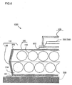
- An embodiment assumes the battery assembly 120 constituted by aligning and disposing sixteen of the cylindrical lithium ion battery cells 140 inside the casing 110. More specifically, in the state in which the lithium ion battery cells 140 are placed on their sides so that the central axes of the lithium ion battery cells 140 extend along the transverse direction, eight of the lithium ion battery cells 140 are disposed in parallel so as to constitute a first battery cell array 121. In addition, similar to the first battery cell array 121, eight of the lithium ion battery cells 140 are disposed so as to constitute a second battery cell array 122.
- the battery assembly 120 is constituted by layering (stacking or header bond) the first battery cell array 121 and the second battery cell array 122 in the height direction. In other words, the battery assembly 120 is constituted by arranging eight arrays of the lithium ion battery cells 140 in the longitudinal direction and two stacks or two layers thereof in the height direction.
- the first battery cell array 121 and the second battery cell array 122 are displaced with respect to each other in the longitudinal direction.
- the first battery cell array 121 is disposed closer to the inlet channel forming plate 111 side than the second battery cell array 122 is, and displaced towards the cooling medium inlet 114 side.
- the second battery cell array 122 is disposed closer to the outlet channel forming plate side than the first battery cell array 121 is, and displaced towards the cooling medium outlet 115 side. As shown in FIG.
- an embodiment assumes the first battery cell array 121 and the second battery cell array 122, which are displaced with respect to each other in the longitudinal direction, so that, for instance, the longitudinal position of the central axis of one of the lithium ion battery cells 140 lying closest to the cooling medium outlet 115 in the first battery cell array 121 lies in the middle between the central axis of one of the lithium ion battery cells 140 lying closest to the cooling medium outlet 115 in the second battery cell array 122 and the central axis of one adjacent thereto of the lithium ion battery cells 140.
- the lithium ion battery cells 140 that constitute the first battery cell array 121 are juxtaposed so as to alternate the directions of the terminals thereof.
- the lithium ion battery cells 140 that constitute the second battery cell array 122 are also juxtaposed so as to alternate the directions of the terminals thereof.
- the sequence from the cooling medium inlet 114 side to the cooling medium outlet 115 side of the terminals of the lithium ion battery cells 140 that constitute the first battery cell array 121 is different from that of the terminals of the lithium ion battery cells 140 that constitute the second battery cell array 122.
- the lithium ion battery cells 140 are disposed so that the terminals thereof facing the side plate 130 side are arranged in order of the negative terminal, the positive terminal, the negative terminal, ..., the positive terminal from the cooling medium inlet 114 side to the cooling medium outlet 115 side.
- the lithium ion battery cells 140 are disposed so that the terminals thereof facing the side plate 130 side are arranged in order of the positive terminal, the negative terminal, the positive terminal, ..., the negative terminal from the cooling medium inlet 114 side to the cooling medium outlet 115 side.
- the battery assembly 120 can be reduced in dimension in the height direction and the higher potential battery block 110a can hence be reduced in size in the height direction.
- the side plate 131 is configured basically the same as the side plate 130.
- a battery module side connection terminal 180 electrically connected to the positive-side of the battery assembly 120 and a battery module side connection terminal 181 electrically connected to the negative-side of the battery assembly 120 are provided only on the side plate 130.
- the connection terminals 180 and 181 are aligned in the longitudinal direction on the top surface of the side plate 130, i.e., on the surface of the inlet channel forming plate 111 side.
- a DC positive-side input/output terminal 183 and a negative-side input/output terminal 184, which have been formed as a subassembly 185 separately from the battery module 100, are connected to the connection terminals 180 and 181, respectively.
- a terminal of the positive-side power cable 610 is connected to the positive-side input/output terminal 183 of the higher potential battery block 110a, and a terminal of a cable that is electrically connected to one end of the SD switch 700 is connected to the negative-side input/output terminal 184 (refer to FIG. 1 ).
- a terminal of a cable electrically connected to the other end of the SD switch 700 is connected to the positive-side input/output terminal 183 of the lower potential battery block 110b.
- a terminal of the negative-side power cable 620 is connected to the negative-side input/output terminal 184 of the lower potential battery block 110b. It is to be noted that in FIG.
- the subassembly 185 of the higher potential battery block 100a represents the state in which the subassembly 185 is covered with a terminal cover whilst the subassembly 185 of the lower potential battery block 100b represents the state in which the terminal cover is removed.
- the side plate 130 is formed into a substantially rectangular flat plate as shown in FIG. 5 .
- Sixteen of the round through-holes 132 that penetrate in the transverse direction are formed on the side plate 130.
- the sixteen through-holes 132 are disposed in line with the sixteen lithium ion battery cells 140 so as to open corresponding to the electrode positions of the sixteen lithium ion battery cells 140 aligned as described earlier. Accordingly, when the battery assembly 120 is housed in the casing 110, the sixteen through-holes 132 on the side plate 130 are closed with a terminal surface on one end of the sixteen lithium ion battery cells 140, and the sixteen through-holes 132 on the side plate 131 side are closed with a terminal surface on the other end of the sixteen lithium ion battery cells 140.
- a protruding section 133 is formed partially encompassing the through-holes 132 on an outer wall surface 170 of the side plate 130, which is opposite to an inner wall surface with which the housing chamber of the battery assembly 120 is formed.
- a plurality of fixing guides 130a are formed so as to dispose the conductive members 150 connected to the lithium ion battery cell 140.
- the protruding section 133 and the fixed guides 130a are each configured to protrude from the outer wall surface 170 so as to prevent the cover member 160 and the conductive members 150 from contacting each other.
- the cover member 160 and the conductive members 150 are metal, for example copper, plate-like members that electrically connect between the lithium ion battery cells 140, and are constituted separately from the side plate 130.
- the conductive member 150a having been integrally formed with the connection terminal 180 and the conductive member 150b having been integrally formed with the connection terminal 181 are integrally formed with the side plate 130.
- the cover member 160 is joined to each of the side plates 130 and 131 via a sealing member 135 and fixed with the fixing means 161 such as bolts, screws, or rivets.
- the sealing member 135 is an elastic, circular sealing member (for instance, a rubber O-ring) that is fitted in a groove 134 formed on the side plate 130. Liquid gasket may instead be used as the sealing member 135.
- the side plate 130 is provided with a gas discharge channel 138 through which the gas, which is mixture gas with fluid including electrolytic solution, that has been released to the gas release chamber between the side plate 130 and the cover member 160 is discharged outside the higher potential battery block 100a.
- An opening section of the gas discharge channel 138 is formed on a lower part of the side plate 130 in view of discharge of fluid such as electrolytic solution included in the gas. More specifically, the opening section is formed on the cooling medium inlet 140 side of the side plate 130 and the side plate 130 on the outlet channel forming plate 118 side.
- a front end section of the gas discharge channel 138 is formed in a pipe-like shape, to which the gas outlet pipe 139 (refer to FIG. 3 ) through which the gas having been discharged through the gas discharge channel 138 is led out is connected.
- connection terminals 810 are aligned in the longitudinal direction on the top surface of the side plate 130, i.e., the surface on the inlet channel forming plate 111 side.
- the connection terminals 810 are integrally formed on the side plate 130 with the same forming material as that of the side plate 130, and disposed on the top surface of the side plate 130 towards the cooling medium inlet 114 side.
- Each of the connection terminals 810 includes a current block section 811 so as to electrically connect the wire (connecting line) 800 that extends from a voltage detection connector 912 of the control unit 900 with a voltage detection conductor, which is not figured, via the current block section.
- the voltage detection connector 912 is provided on each end in the transverse direction of the control unit 900.
- the connecting wire 800 connected to the connection terminals 810 provided on the higher potential battery block 100a is connected to the connector 912 of the control unit 900 disposed above the higher potential battery block 100a.
- the connecting wire 800 connected to the connection terminals 810 provided on the lower potential battery block 100b is connected to the connector 912 of the control unit 900 disposed above the lower potential battery block 100b.
- the length of the connecting wire 800 is set so as to be equivalent to the distance between each of the connection terminals 810 and the connector 912 corresponding thereto.
- the length of the connecting wire 800 connected to the connection terminals 810 of the higher potential battery block 100a is set so as not to reach the connector 912 of the lower potential battery block 100b.
- the current block section 811 includes a fuse wire that is fused in the event of an abnormality of the control circuit 900 and the wire 800 so as to block current from the battery assembly 120 and protect the product.
- a reference numeral 500 represents a chassis of an electric powered vehicle on which a drive device that drives travel on electric power at the battery module 100 is mounted.
- the battery module 100 is bolted to the chassis 500 through the module base 101, which is a mounting member, and is also electrically connected to the chassis.
- the module base 101 is fixed and fastened to the lower base LOB and electrically connected to the lower base
- the lower base LOB is fixed and fastened to the upper base UPB and electrically connected to the upper base.
- the base 910 of the control unit 900 is fixed and fastened to the upper base UPB and electrically connected to the upper base.
- the battery controller 300 and the cell controller are mounted on the base 910 so that their negative terminals are electrically conducting.
- This structure allows the negative terminals of the battery controller 300 and the cell controller 200 mounted on the base 910 to be electrically connected to the chassis 500 through the base 910, the upper base UPB, the lower base LOB, and the module base 101.
- the negative terminals of the control unit 900 i.e., the battery controller 300 and the cell controller 200, can thus be in electrical communication with the chassis 500 without using a ground wire.
- the base 910, the upper base UPB, and the lower base LOB of the control unit 900 are of aluminium die cast and hence include high conductivity and strength.
- the module base 101 is formed from a steel plate and hence includes sufficient conductivity and high strength.
- the electrical storage device according to the present invention may be varied as follows.
- the electrical storage device according to the present invention may therefore be an electrical storage device in any mode, as long as it includes a conductive battery house casing electrically connected to a chassis, a plurality of battery cells held in the battery house casing, and a control unit that includes a circuit that manages the plurality of battery cells and is mounted on the battery house casing so that a negative terminal of the circuit and the battery house casing are electrically conducting.
Description
- The present invention relates to an electrical storage device that includes a battery module with a plurality of battery cells housed in a battery house casing and a management circuit thereof.
- Electric vehicles that use a rotating electric machine as a driving source and hybrid vehicles that use both an internal combustion engine and a rotating electric machine have recently been put to practical use. Those types of vehicles are mounted with a battery that supplies electrical energy to the rotating electric machine, and such battery to be mounted includes rechargeable secondary batteries such as a nickel-cadmium battery, a nickel-metal hydride battery, and a lithium ion battery.
- A secondary battery is usually constituted as a battery module with a plurality of battery cells placed on top of one another, the bottom surface of a battery house casing is attached to the vehicle body through a module base, and a battery controller is mounted in the neighborhood thereof such as the top surface of the battery house casing or a side surface to manage the state of electrical storage, as disclosed in Japanese Laid Open Patent Publication No.
2004-319304 - From
US Laid Open Patent Publication No. 2006/279086 A1 an on-vehicle battery and electric unit assembly including a battery mounted to a body of a vehicle driven by an engine and an electric unit in which components of an electrical circuit connected to the battery are housed in a unit case provided with a positive DC terminal and a negative DC terminal connected to a positive terminal and a negative terminal of the battery are known, wherein the electric unit is placed adjacent to the battery, and the positive terminal and the negative terminal of the battery are connected to the positive DC terminal and the negative DC terminal of the electric unit by a positive busbar and a negative busbar, respectively. - A battery controller includes a built-in electric circuit, which needs to be grounded for its normal operation, and therefore the battery controller and the module base are often connected through a thick ground wire.
- When a battery controller and a module base are connected through a thick ground wire, the cost of the ground wire is high and its assembly work is complicated.
- In order to solve this problem, the invention provides an electrical storage device having the features of claim 1.
- An electrical storage device according to a first further aspect of the present invention comprises: a conductive battery house casing electrically connected to a chassis; a plurality of battery cells held in the battery house casing; and/or a control unit that comprises a circuit that manages the plurality of battery cells and is mounted on the battery house casing so that a negative terminal of the circuit and the battery house casing are electrically conducting.
- According to a second aspect of the present invention, the electrical storage device according to the first aspect further comprises a mounting member that electrically connects and fixes the battery house casing to the chassis.
- According to a third aspect of the present invention, in the electrical storage device according to the first aspect, the battery house casing may comprise: a conductive lower base; a conductive upper base that is connected to the lower base from above to form a casing body circularly formed with both side surfaces being open; and side plates that hold the battery cells while closing the both side surfaces of the casing body.
- According to a fourth aspect of the present invention, in the electrical storage device according to the first aspect, the battery house casing may comprise a circular member with both side surfaces being open; and side plates that hold the battery cells while closing the both side surfaces of the circular member.
- According to a fifth aspect of the present invention, the electrical storage device according to the fourth aspect may further comprise a mounting member that electrically connects and fixes the battery house casing to the chassis.
- According to a sixth aspect of the present invention, the electrical storage device according to the fifth aspect may further comprise a plurality of the battery house casings in which a battery assembly constituted with the plurality of battery cells is housed, wherein: the control unit may be mounted astride a top surface of the plurality of battery house casings.
- According to a seventh aspect of the present invention, in the electrical storage device according to the first to sixth aspects, the battery house casing may be formed from die-cast aluminium.
- An electric powered vehicle according to an eighth aspect of the present invention comprises: a travel drive device that generates travel drive on electric power; an electrical storage device according to the fourth to seventh aspects that generates the electric power; and a vehicle body on which the travel drive device is provided, wherein: the battery house casing is mounted on the vehicle body through a mounting member so that the vehicle body is set to ground potential.
- An electrical storage device according to a ninth aspect of the present invention comprises: a first and second conductive battery house casings being juxtaposed; a first and second battery assemblies, each of which is constituted with a plurality of battery cells, that are held in the first and second battery house casings, respectively; and a control unit that comprises a circuit which manages the first and second battery assemblies and that is mounted on the first and second battery house casings so that a negative terminal of the circuit and the first and second battery house casings are electrically conducting and the first and second battery house casings are integrated.
-
-
FIG. 1 is a block diagram showing the structure of a vehicle-mounted electric machine system in which an electrical storage device according to an embodiment of the present invention is used. -
FIG. 2 is a perspective view showing the external structure of a whole lithium ion battery device according to an embodiment of the present invention. -
FIG. 3 is a perspective view of the lithium ion battery device shown inFIG. 2 , seen from a cooling medium inlet side. -
FIG. 4 is a perspective view showing the external appearance structure of a whole battery block of an electrical storage device constituting the lithium ion battery device according to an embodiment. -
FIG. 5 is an exploded perspective view of the battery block shown inFIG. 4 . -
FIG. 6 is a vertical sectional view of a battery block, illustrating vehicle body grounding of the battery controller. - The electrical storage device according to an embodiment of the present invention will now be explained in detail with reference to the drawings.
- An example will be explained in terms of the electrical storage device according to an embodiment being applied to an electrical storage device that constitutes a vehicle-mounted power source system for an electric powered vehicle, in particular an electric vehicle. An electric vehicle includes a hybrid electric vehicle that has both an internal combustion engine and an electric machine as a driving source of the vehicle and a pure electric vehicle that has an electric machine as an only driving source of the vehicle.
- The structure of the vehicle-mounted electric machine system (electrical machine driving system) that includes the electrical storage device according to an embodiment will now be explained with reference to
FIG. 1 . - The vehicle-mounted electric machine system includes a
motor generator 10, aninverter device 20, avehicle controller 30 that controls the whole vehicle, and anelectrical storage device 1000 that constitutes a vehicle-mounted power source. Theelectrical storage device 1000 includes a plurality of storage batteries and is constituted as, for instance, a lithium ion battery device that includes a plurality of lithium ion battery cells. - An electric powered vehicle, including an electric vehicle and a hybrid vehicle, on which such vehicle-mounted electric machine system is mounted includes a travel drive device that generates travel drive on electric power, the electrical storage device according to the present invention that supplies electric power to the travel drive device, and a vehicle body that is provided with the travel drive device. The electrical storage device includes a battery block constituted by housing a battery assembly constituted with a plurality of battery cells into a conductive casing and a control unit that includes a battery controller and a cell controller that manage the battery cells. In the electrical storage device according to the present invention, in particular, in order to provide a ground path of a negative terminal of the circuit board of the battery controller and the cell controller, the controller is grounded to the vehicle body grounding only by integrating the control unit to the battery block without separately routing a conventional ground wire.
- The
motor generator 10 is a three-phase alternate-current machine. Any of two types of three-phase AC machine, a synchronous machine and an induction machine, may be adopted. In operating mode requiring rotational power such as during power running of the vehicle or starting the internal combustion engine, themotor generator 10 drives the motor and supplies the generated rotational power to driven bodies such as wheels and the engine. In this case, the vehicle-mounted electric machine system converts DC (direct current) power into three-phase AC electric power and supplies it from the lithiumion battery device 1000 to themotor generator 10 via theinverter device 20, which is an electric power conversion device. - In operating mode requiring power generation, for instance, during regeneration such as decelerating or braking the vehicle or when the lithium
ion battery device 1000 needs to be recharged, themotor generator 10 receives drive power from the wheels or the engine and works as a generator to generate three-phase AC electric power. In this case, the vehicle-mounted electric machine system converts the three-phase AC electric power from themotor generator 10 into DC power via theinverter device 20 and supplies it to the lithiumion battery device 1000. As a result, electric power is accumulated in the lithiumion battery device 1000. - The
motor generator 10 is an electric machine that is operated by a magnetic influence of an armature, for example, a stator and a field, for example, a rotor, that is disposed opposite the armature and rotatably supported. Themotor generator 10 assumes a structure that allows the axis of rotation of the field to be mechanically connected to the axis of rotation of the driven bodies such as the wheels and the engine so that rotational power can be directed to and from the driven bodies. - The armature is a part that is to be supplied with three-phase AC electric power to generate a rotating magnetic field when the
motor generator 10 is engaged in operation as a motor or as a generator. The armature includes an armature core, that is, a stator core, which is a magnetic material, and a three-phase armature winding, that is, a stator winding, attached to the armature core. - The field is a part that generates field magnetic flux when the
motor generator 10 is engaged in operation as a motor or a generator. The field includes a field core, that is, a rotor core, which is a magnetic material, and a permanent magnet, a field winding, that is, a rotor winding, or conductor bar, that are attached to the field core, or the field core and both a permanent magnet and a field winding (or a conductor bar). The field winding generates magnetic flux by being excited with field current supplied from an external power source. - The
inverter device 20 is an electronic circuit device that controls the power conversion described above, i.e., the conversion from DC power to three-phase AC electric power and from three-phase AC electric power to DC power, by operation (ON/OFF) of a switching semiconductor device. Theinverter device 20 includes apower module 21, adriver circuit 22, amotor controller 23, and asmoothing capacitor 24. - The
power module 21 is a power conversion circuit that includes six switching semiconductor devices to perform the power conversion described above by switching operation (ON/OFF) of the six switching semiconductor devices. A metal-oxide semiconductor field-effect transistor (MOSFET) or an insulated gate bipolar transistor (IGBT) is used for the switching semiconductor devices. When thepower module 21 is constituted with a MOSFET, parasitic diodes are electrically connected in inverse parallel between a drain electrode and a source electrode. When thepower module 21 is constituted with an IGBT, on the other hand, it is separately necessary for diodes to be electrically connected in inverse parallel between a collector and an emitter. The power conversion circuit is constituted with a three-phase bridge circuit, in which series circuits (an arm for one phase), each of which includes two (an upper arm and a lower arm) switching semiconductor devices electrically connected in series, are electrically connected in parallel for three phases. - The side of each upper arm opposite the lower arm connection side is electrically connected to a DC positive pole-side module terminal, and the side of each lower arm opposite the upper arm connection side is electrically connected to a DC negative pole-side module terminal. The middle point of each of the upper and the lower arms, i.e., the sides of each of the upper and the lower arms connecting to each other, are electrically connected to an AC-side module terminal. The DC positive pole-side module terminal and the DC negative pole-side module terminal are electrically connected to a DC positive pole-side external terminal and a DC negative pole-side external terminal, respectively. The DC positive pole-side external terminal and the DC negative pole-side external terminal are power source-side terminals to direct DC power to and from the lithium
ion battery device 1000 and electrically connected with apower cable 600 that extends from the lithiumion battery device 1000. The AC-side module terminal is electrically connected to an AC-side external terminal. The AC-side external terminal is a load side terminal to direct three-phase AC electric power to and from themotor generator 10 and electrically connected with a load cable that extends from themotor generator 10. - The
smoothing capacitor 24 is electrically connected in parallel between the DC positive pole-side and the DC negative pole-side of the power conversion circuit in order to inhibit a voltage fluctuation that arises from a high speed switching operation of the switching semiconductor devices constituting the power conversion circuit. - The
motor controller 23 is an electronic circuit device to control the switching operation of the six switching semiconductor devices constituting the power conversion circuit. Based upon a torque command having been output from thevehicle controller 30 that controls a higher-order control unit, for instance the whole vehicle, themotor controller 23 generates a switching operation command signal, for example, PWM (pulse width modulation) signal, to the six switching semiconductor devices. The generated command signal is output to thedriver circuit 22. - Based upon the switching operation command signal having been output from the
motor controller 23, thedriver circuit 22 generates a drive signal to the six switching semiconductor devices constituting the power conversion circuit. The generated drive signal is output to a gate electrode of the six switching semiconductor devices constituting the power conversion circuit. As a result, switching (ON/OFF) of the six switching semiconductor devices constituting the power conversion circuit is controlled based upon the drive signal having been output from thedriver circuit 22. - The lithium
ion battery device 1000 includes abattery module 100 to accumulate and release electrical energy, i.e., to charge and discharge DC power, and acontrol unit 900 to manage and control the state of the battery module 100 (refer toFIG. 2 ). - The
battery module 100 is constituted with two battery blocks or battery packs, i.e., a higherpotential battery block 100a and a lowerpotential battery block 100b that are electrically connected in series. A battery assembly is housed in each of the battery blocks. Each of the battery assemblies is constituted with a combination of a plurality of lithium ion battery cells that are electrically connected in series. The structure of each of the battery blocks will be described later. - An SD (service disconnect)
switch 700 is provided between the negative pole-side, or lower potential side, of the higherpotential battery block 100a and the positive pole-side, or higher potential side, of the lowerpotential battery block 100b. TheSD switch 700, a safety device provided to ensure the safety at maintenance and inspection of the lithiumion battery device 1000, is constituted with an electrical circuit in which a switch and a fuse are electrically connected in series, and to be operated by a serviceman at the time of maintenance and inspection. - The
control unit 900 is constituted with a higher-order (parent)battery controller 300 and a lower-order (child)cell controller 200. Although not shown in the figures, thecontrol unit 900 is constituted by mounting the control board of thebattery controller 300 and the control board of thecell controller 200 onto a board mount surface of a base 910 formed of a conductive material. When those control boards are mounted, the negative terminal of each of the control boards of thebattery controller 300 and thecell controller 200 is electrically connected to thebase 910. It is to be noted that in the interests of brevity, grounding of thebattery controller 300 and thecell controller 200 will be hereinafter explained as a synonym of connection of the negative terminal of each of the control boards to the vehicle body grounding potential. - As described below, the higher
potential battery block 100a and the lowerpotential battery block 100b are juxtaposed, and thecontrol unit 900 is disposed astride their top surfaces. In other words, thecontrol unit 900 and the base 910 are mounted to theblocks blocks - It is to be noted that as described later, the
battery blocks conductive casing 110. Thecasing 110 is then electrically and mechanically connected to the vehicle body through aconductive module base 101. The potential at the negative terminals of thebattery controller 300 and thecell controller 200 hence becomes equal to the ground potential at the vehicle body through thecasing 110. As a result, a ground wire through which thebattery controller 300 and thecell controller 200 are grounded to the vehicle body is not required. - The
battery controller 300 manages and controls the state of the lithiumion battery device 1000 and notifies thevehicle controller 30 and themotor controller 23, which are higher-order control units, of the state of the lithiumion battery device 1000 and a charge/discharge control command to control allowable charge/discharge electric power and the like. The management and control of the state of the lithiumion battery device 1000 include measurement of the voltage and current at the lithiumion battery device 1000, arithmetic operations of the state of charge (SOC), the state of health (SOH), and the like at the lithiumion battery device 1000, measurement of temperature at each of the battery blocks, output of a command to the cell controller 200 (for example, a command to measure the voltage at each of the lithium ion battery cells, a command to adjust the stored charge at each of the lithium ion battery cells, and the like), and the like. - The
cell controller 200 is a so-called hand and foot of thebattery controller 300, which, according to a command from thebattery controller 300, manages and controls the state of the plurality of lithium ion battery cells and is constituted with a plurality of integrated circuits (IC). The management and control of the state of the plurality of lithium ion battery cells include measurement of the voltage at each of the lithium ion battery cells, adjustment of the stored charge at each of the lithium ion battery cells, and the like. Each of the integrated circuits is designated to a plurality of corresponding lithium ion battery cells, and manages and controls the state of the plurality of corresponding lithium ion battery cells. - The power source of the
battery controller 300 uses a battery for auxiliaries, in case of an automobile, a lead acid battery with a nominal output voltage of 12V, that is mounted as a power source for vehicle-mounted auxiliaries, for instance, lights and audio equipment. For this reason, voltage (12V for instance) is applied from the battery for auxiliaries to thebattery controller 300. Thebattery controller 300 steps down (steps down to 5V for example) the applied voltage via a power source circuit constituted with a DC-DC power converter and applies the stepped down voltage to electronic components that constitute thebattery controller 300 as a drive voltage. As a result, the electronic components that constitute thebattery controller 300 are actuated. - The plurality of corresponding lithium ion battery cells are used as a power source of the integrated circuits that constitute the
cell controller 200. For this reason, thecell controller 200 and thebattery module 100 are electrically connected with each other through a connectingwire 800. Voltage of the highest potential at the plurality of corresponding lithium ion battery cells is applied to each of the integrated circuits through the connectingwire 800. Each of the integrated circuits steps down the applied voltage via the power source circuit (steps down to 5V for example) and uses it as an operational power source. - A signal that has been output from an ignition key switch is input to the
battery controller 300. The signal that has been output from the ignition key switch is used as a signal of start-up and shutdown of the lithiumion battery device 1000. - When the ignition key switch enters the ON state, in the
battery controller 300, the power source circuit is actuated based upon an output signal from the ignition key switch, and a drive voltage is applied from the power source circuit to a plurality of electronic circuit components so that the plurality of electronic circuit components are actuated. Thebattery controller 300 starts up as a result. When thebattery controller 300 starts up, a start-up command is output from thebattery controller 300 to thecell controller 200. In thecell controller 200, based upon the start-up command from thebattery controller 300, the power source circuits of the plurality of integrated circuits are actuated in sequence and the plurality of integrated circuits start up in sequence. Thecell controller 200 starts up as a result. When thecell controller 200 starts up, predetermined initial processing is executed so that the lithiumion battery device 1000 starts up. - The predetermined initial processing includes, for instance, measurement of the voltage at each of the lithium ion battery cells, an abnormality diagnosis, measurement of the voltage and current at the lithium
ion battery device 1000, measurement of the temperature at each of the battery blocks, arithmetic operations on the state of charge and the state of health of the lithiumion battery device 1000, arithmetic operations of the allowable charge/discharge electric power of the lithiumion battery device 1000, and the like. - When the ignition key switch enters the OFF state, a stop command is output from the
battery controller 300 to thecell controller 200. When thecell controller 200 receives the stop command, predetermined termination processing is executed, and then the power source circuits of the plurality of integrated circuits stop in sequence and the plurality of integrated circuits stop in sequence. Thecell controller 200 stops as a result. When thecell controller 200 stops and a communication with thecell controller 200 is blocked, in thebattery controller 300 the operations of the power source circuits stop and the operations of the plurality of electronic circuit components stop. As a result, thebattery controller 300 stops and the lithiumion battery device 1000 stops. - The predetermined termination processing includes, for instance, measurement of the voltage at each of the lithium ion battery cells, adjustment of the stored charge at each of the lithium ion battery cells, and the like.
- In-vehicle local area network communication is used for transmission of information between the
battery controller 300 and higher-order control units such as thevehicle controller 30 and themotor controller 23. Local interconnect network communication, which conforms to the in-vehicle local area network communication, is used for transmission of information between thebattery controller 300 and thecell controller 200. - A positive terminal of the higher
potential battery block 100a and the DC positive-side external terminal of theinverter device 20 are electrically connected with each other through a positive-side power cable 610. A negative terminal of the lowerpotential battery block 100b and the DC negative-side external terminal of theinverter device 20 are electrically connected with each other through a negative-side power cable 620. - A
junction box 400 is provided along thepower cable 600. A relay mechanism constituted with amain relay 410 and aprecharge circuit 420 is housed in thejunction box 400. The relay mechanism is an open/close section to allow electrical conduction and block between thebattery module 100 and theinverter device 20, more specifically, the relay mechanism allows conduction between thebattery module 100 and theinverter device 20 at the start-up of the vehicle-mounted electrical machine system while it allows block between thebattery module 100 and theinverter device 20 at the time of stop or in the event of an abnormality of the vehicle-mounted electrical machine system. The relay mechanism thus controls between the lithiumion battery device 1000 and theinverter device 20 so as to ensure a high level of safety of the vehicle-mounted electrical machine system. - Drive of the relay mechanism is controlled by the
motor controller 23. Upon reception of a notification of start-up completion of the lithiumion battery device 1000 from thebattery controller 300, themotor controller 23 outputs a conduction command signal to the relay mechanism at the start-up of the vehicle-mounted electrical machine system so as to drive the relay mechanism. Upon reception of an OFF output signal from the ignition key switch at the time of stop of the vehicle-mounted electrical machine system, or upon reception of an abnormality signal from thevehicle controller 30 in the event of an abnormality of the vehicle-mounted electrical machine system, themotor controller 23 outputs a block command signal to the relay mechanism so as to drive the relay mechanism. - The
main relay 410 is constituted with a positive-sidemain relay 411 and a negative-sidemain relay 412. The positive-sidemain relay 411 is provided along the positive-side power cable 610 and controls an electrical connection between a positive-side of the lithiumion battery device 1000 and a positive-side of theinverter device 20. The negative-sidemain relay 412 is provided along the negative-side power cable 620 and controls an electrical connection between a negative-side of the lithiumion battery device 1000 and a negative-side of theinverter device 20. - The
precharge circuit 420 is a series circuit in which aprecharge relay 421 and aresistor 422 are electrically connected in series, and is electrically connected in parallel to the positive-sidemain relay 411. - At the start-up of the vehicle-mounted electrical machine system, the negative-side
main relay 412 is turned on and then theprecharge relay 421 is turned on. As a result, the current supplied from the lithiumion battery device 1000 is regulated by theresistor 422 and then is supplied to the smoothingcapacitor 24 and charged. After the smoothingcapacitor 24 is charged up to a predetermined voltage, the positive-sidemain relay 411 is turned on and theprecharge relay 421 is released. As a result, the main current is supplied from the lithiumion battery device 1000 to theinverter device 20 via the positive-sidemain relay 411, and the main current at this time becomes equal to or less than the allowable current at the positive-sidemain relay 411 and the smoothingcapacitor 24. Accordingly, the smoothingcapacitor 24 and the positive-sidemain relay 411 can be protected from a large current at the start-up of the vehicle-mounted electrical machine system without having abnormalities, such as significant heat generated at this time which may damage the smoothingcapacitor 24 and the fixed and moving contacts of the positive-sidemain relay 411 which may become fused, caused as a large initial current flowing in momentarily from the lithiumion battery device 1000 to theinverter device 20 due to the electrical charge at the smoothingcapacitor 24 being substantially zero. - An
ammeter 430 is housed inside thejunction box 400. Theammeter 430 is provided so as to detect current supplied from the lithiumion battery device 1000 to theinverter device 20. An output line of theammeter 430 is electrically connected to thebattery controller 300. Based upon a signal that has been output from theammeter 430, thebattery controller 300 detects the current supplied from the lithiumion battery device 1000 to theinverter device 20. The current detection information is notified from thebattery controller 300 to themotor controller 23, thevehicle controller 30, and the like. Theammeter 430 may be provided outside thejunction box 400. A current detection section of the lithiumion battery device 1000 may not be just on thebattery module 100 side of the positive-sidemain relay 411 but may also be on theinverter device 20 side of the positive-sidemain relay 411. - It is to be noted that a voltmeter to detect the voltage at the lithium
ion battery device 1000 may be housed inside thejunction box 400. An output line of the voltmeter, similar to that of theammeter 430, is electrically connected to thebattery controller 300. Based upon an output signal from the voltmeter, thebattery controller 300 detects the overall voltage at the lithiumion battery device 1000. The voltage detection information is notified to themotor controller 23 and thevehicle controller 30. It is preferable that a voltage detection section of the lithiumion battery device 1000 is positioned on both thebattery module 100 side and theinverter device 20 side of the relay mechanism. - A positive-
side capacitor 500 is electrically connected between the positive-side power cable 610 and a chassis ground (assuming a potential equal to that at the vehicle chassis) of the lithiumion battery device 1000. A negative-side capacitor 510 is electrically connected between the negative-side power cable 620 and a chassis ground of the lithiumion battery device 1000. The positive-side capacitor 500 and the negative-side capacitor 510 are provided in order to prevent erroneous operation of thebattery controller 300 and thecell controller 200, which are low-rate electrical circuits, and destruction of the integrated circuit (IC) constituting thecell controller 200 due to a surge voltage, by eliminating noise generated via theinverter device 20. While theinverter device 20 includes a noise removal filter, the positive-side capacitor 500 and the negative-side capacitor 510 are provided so as to even more effectively prevent erroneous operations of thebattery controller 300 and thecell controller 200, which are low-rate electrical circuits, and destruction of the integrated circuit (IC) constituting thecell controller 200 due to a surge voltage, and improve the noise withstanding reliability of the lithiumion battery device 1000. - Next, the structure of the lithium
ion battery device 1000 will be explained in reference toFIG. 2 to FIG. 6 .FIGS. 2 and3 show perspective views presenting the overall structure of the lithiumion battery device 1000.FIG. 4 shows a perspective view of the battery block that constitutes the lithiumion battery device 1000, andFIG. 5 shows an exploded perspective view of the battery block shown inFIG. 4 . - The lithium
ion battery device 1000 is constituted with two main units of thebattery module 100 and thecontrol unit 900. The structure of thebattery module 100 will now be explained. - As described earlier, the
battery module 100 is constituted with the higherpotential battery block 100a and the lowerpotential battery block 100b, and the twobattery blocks potential battery block 100a and the lowerpotential battery block 100b include exactly the same structure.FIGS. 4 and5 therefore present only the higherpotential battery block 100a as a representative example of the higherpotential battery block 100a and the lowerpotential battery block 100b, and an explanation of the detailed structure of the lowerpotential battery block 100b will thus be curtailed. - As shown in
FIG. 2 , the higherpotential battery block 100a and the lowerpotential battery block 100b are adjacently disposed in parallel with each other so that longitudinal directions of each of the blocks are in parallel. The higherpotential battery block 100a and the lowerpotential battery block 100b are juxtaposed on themodule base 101 and, as described later, thecontrol unit 900 is disposed astride the top surfaces of the higherpotential battery block 100a and the lowerpotential battery block 100b, so that both of theblocks base 910 of thecontrol unit 900. Themodule base 101 is constituted with a rigid, thin-wall metal plate (a steel plate for example) that is divided into three in a transverse direction and fixed to the vehicle. In other words, themodule base 101 is constituted with three members disposed on the both ends and the middle section in the transverse direction. By adopting this structure, the surface of themodule base 101 can be flush with the lower surface of each of thebattery blocks battery module 100 in the height direction can be further reduced. - As shown in
FIG. 5 , the higherpotential battery block 100a is mainly constituted with the battery house casing (hereinafter referred to as the casing) 110 and abattery assembly 120. Thebattery assembly 120 is housed and held inside thecasing 110. - The
casing 110 constitutes a substantially rectangular block housing with an upper base UPB, a lower base LOB, andside plates casing 110 is constituted with a combination of three members. An explanation will now be made with reference toFIG. 3 to FIG. 5 . The upper base UPB includes an inletchannel forming plate 111, an outlet-side guide plate 113, a coolingmedium inlet 114, and a coolingmedium inlet duct 116 that are integrally formed from die-cast aluminium. The lower base LOB includes an outletchannel forming plate 118, an inlet-side guide plate 112, a coolingmedium outlet 115, and a coolingmedium outlet duct 117 that are integrally formed from die-cast aluminium. It is to be noted that the upper base UPB and the lower base LOB are casing bodies bolted with each other at the longitudinal end portions so as to form a circular member with both of the side surfaces being open. The interior space of thecasing 110 functions as a housing chamber in which thebattery assembly 120 constituted with a plurality ofbattery cells 140 is housed and also functions as a cooling channel through which a cooling medium, i.e., cooling air, flows to cool down thebattery assembly 120. - It is to be noted that in the explanation provided below, a direction with the longest dimension of the
casing 110 and a direction from the coolingmedium inlet 114 side to the coolingmedium outlet 115 side are defined as a longitudinal direction. A direction in which two side surfaces, i.e., the twoside plates side guide plate 112 and the outlet-side guide plate 113, that face each other in the longitudinal direction of thecasing 110, face each other, a central axial direction of the lithium ion battery cells 140 (a direction in which two electrodes of the positive terminal and the negative terminal face each other), and a direction in which aconductive member 150, which electrically connects two of the lithiumion battery cells 140, and two of the lithiumion battery cells 140 face each other are defined as a transverse direction. In addition, a direction in which the inletchannel forming plate 111 and the outletchannel forming plate 118 face each other is defined as a height direction regardless of the installation orientation of thebattery module 100. - The inlet
channel forming plate 111 is a rectangular flat plate that forms the top surface of thecasing 110. The outletchannel forming plate 118 is a flat plate that forms the bottom surface of thecasing 110. The inletchannel forming plate 111 and the outletchannel forming plate 118 are displaced with respect to each other in the longitudinal direction. As a result, the positions of the longitudinal end portions of the inletchannel forming plate 111 and the outletchannel forming plate 118 are displaced with respect to each other in the longitudinal direction. - The inlet
channel forming plate 111, i.e., the top surface of the upper base UPB is provided with a mountingsection 110S with which thecontrol unit 900 is mounted. A mountingsection 110S is an internally threaded boss. As shown inFIGS. 1 and2 , thebase 910 of theconductive control unit 900, on which thebattery controller 300 and thecell controller 200 are to be mounted, is bolted to and in electrical communication with the mountingsections 110S of the pair ofbattery blocks battery controller 300 and thecell controller 200 are mounted on the base 910 so that their negative terminals are in electrical communication with thebase 910 of thecontrol unit 900. Thecontrol unit 900 is mounted astride both thebattery blocks potential battery block 100a and the lowerpotential battery block 100b. In other words, both theblocks control unit 900, i.e., the base 910 onto thebattery blocks - It is to be noted that the
battery blocks battery cells 140 in theconductive casing 110. Thecasing 110 is then electrically and mechanically connected to the vehicle body (chassis) through theconductive module base 101. The potential at the negative terminals of thebattery controller 300 and thecell controller 200 therefore becomes equal to the ground potential at the vehicle body through thecasing 110. As a result, a ground wire through which thebattery controller 300 and thecell controller 200 are grounded to the vehicle body is not required. - The inlet-
side guide plate 112 is a plate-like member that forms one side of the side surfaces facing the longitudinal direction of thecasing 110. The outlet-side guide plate 113 is a plate-like member that forms the other side of the side surfaces facing the longitudinal direction of thecasing 110. - The cooling
medium inlet 114 that constitutes an inlet via which cooling air, a cooling medium, is led into thecasing 110 is formed between the inletchannel forming plate 111 and the inlet-side guide plate 112. The coolingmedium inlet 114 is provided with the coolingmedium inlet duct 116 to lead cooling air to the coolingmedium inlet 114. As described above, the inletchannel forming plate 111 and the outletchannel forming plate 118 are displaced with respect to each other, and the inlet-side end of thecasing 110 is formed in steps. As a result, a space is formed in the longitudinal direction between the coolingmedium inlet 114 and the inlet-side guide plate 112. Agas outlet pipe 139 that will be described later is housed in this space. As shown inFIG. 3 , the inlet-side guide plate 112 is disposed at the back of thegas outlet pipe 139. By adopting this structure, the dimension of thebattery module 1000 can be reduced in the longitudinal direction. The coolingmedium outlet 115 that constitutes an outlet via which cooling air is led from inside thecasing 110 is formed between the outletchannel forming plate 118 and the outlet-side guide plate 113. The coolingmedium outlet 115 is provided with the coolingmedium outlet duct 117 to lead cooling air from the coolingmedium outlet 115 to the exterior. - The cooling
medium inlet 114 and the coolingmedium outlet 115 are displaced with respect to each other in the height direction (the direction in which the inletchannel forming plate 111 and the outletchannel forming plate 118 face each other). In other words, the coolingmedium inlet 114 is positioned on the inletchannel forming plate 111 side, and the coolingmedium outlet 115 is positioned on the outletchannel forming plate 118 side. - The inlet
channel forming plate 111, the outletchannel forming plate 118, the inlet-side guide plate 112, the outlet-side guide plate 113, the coolingmedium inlet 114, and the coolingmedium outlet 115, which constitute the upper base UPB and the lower base LOB, and theside plates casing 110 and allow the cooling medium that has been led inside thecasing 110 via the coolingmedium inlet 114 to be discharged through the coolingmedium outlet 115 without leaking out. - The
side plates casing 110 in the transverse direction, and are moldings made of a resin such as PBT that has electrical insulation properties. The wall thicknesses of theside plates channel forming plate 111, the outletchannel forming plate 118, the inlet-side guide plate 112, and the outlet-side guide plate 113. The structures of theside plates - A
cover member 160, which is called as a side cover, is provided outside theside plates battery assembly 120. While only thecover member 160 provided outside theside plate 130 is illustrated inFIG. 5 , thecover member 160 is provided also outside theside plate 131. Thecover member 160 is fixed to theside plate 130 with a fixing means 161 such as bolts or rivets. - The
cover plate 160 is a flat plate prepared by pressing a metal plate of steel, aluminium, or the like, or a flat plate prepared by shaping a resin of PBT or the like, and is configured into substantially the same shape as the planar shape of theside plate 130. Thecover plate 160 has a region that includes a section corresponding to through-holes 132 of theside plate 160 to be described later uniformly bulging towards the opposite side of theside plate 130. As a result, a space is formed between thecover plate 160 and theside plate 130. This space functions as a gas release chamber, or a gas release channel, through which mist gas having been emitted from the lithiumion battery cells 140 is released separately from the cooling medium that flows through the cooling channel. - The
battery assembly 120 is an assembly (lithium ion battery cell group) of the plurality of lithiumion battery cells 140. The plurality of lithiumion battery cells 140 are aligned and housed in the housing chamber formed inside thecasing 110, sandwiched by theside plates conductive members 150 called bus bars. - The lithium
ion battery cells 140 assume a structure in columnar shape, constituted with component parts such as a cell element and a safety valve which are housed inside a battery case in which electrolytic solution has been injected. A positive-side safety valve is a split valve that splits when the pressure inside the battery case becomes a predetermined pressure due to an abnormality such as overcharge. The safety valve functions as a fuse mechanism that splits so as to block the electrical connection between a battery lid and the positive side of the cell element, and functions as a decompression mechanism that emits gas generated inside the battery case, i.e., mist carbon dioxide gas (the jet) including electrolytic solution, to the outside of the battery case. - The negative side of the battery case is also provided with a split groove, which splits when the pressure inside the battery case becomes a predetermined pressure due to an abnormality such as overcharge. As a result, the gas generated inside the battery case can also be emitted from the negative terminal side. The nominal output voltage of the lithium
ion battery cell 140 is 3.0 to 4.2V and the average nominal output voltage is 3.6V. - An embodiment assumes the
battery assembly 120 constituted by aligning and disposing sixteen of the cylindrical lithiumion battery cells 140 inside thecasing 110. More specifically, in the state in which the lithiumion battery cells 140 are placed on their sides so that the central axes of the lithiumion battery cells 140 extend along the transverse direction, eight of the lithiumion battery cells 140 are disposed in parallel so as to constitute a firstbattery cell array 121. In addition, similar to the firstbattery cell array 121, eight of the lithiumion battery cells 140 are disposed so as to constitute a secondbattery cell array 122. Thebattery assembly 120 is constituted by layering (stacking or header bond) the firstbattery cell array 121 and the secondbattery cell array 122 in the height direction. In other words, thebattery assembly 120 is constituted by arranging eight arrays of the lithiumion battery cells 140 in the longitudinal direction and two stacks or two layers thereof in the height direction. - The first
battery cell array 121 and the secondbattery cell array 122 are displaced with respect to each other in the longitudinal direction. In other words, the firstbattery cell array 121 is disposed closer to the inletchannel forming plate 111 side than the secondbattery cell array 122 is, and displaced towards the coolingmedium inlet 114 side. On the other hand, the secondbattery cell array 122 is disposed closer to the outlet channel forming plate side than the firstbattery cell array 121 is, and displaced towards the coolingmedium outlet 115 side. As shown inFIG. 5 , an embodiment assumes the firstbattery cell array 121 and the secondbattery cell array 122, which are displaced with respect to each other in the longitudinal direction, so that, for instance, the longitudinal position of the central axis of one of the lithiumion battery cells 140 lying closest to the coolingmedium outlet 115 in the firstbattery cell array 121 lies in the middle between the central axis of one of the lithiumion battery cells 140 lying closest to the coolingmedium outlet 115 in the secondbattery cell array 122 and the central axis of one adjacent thereto of the lithiumion battery cells 140. - The lithium
ion battery cells 140 that constitute the firstbattery cell array 121 are juxtaposed so as to alternate the directions of the terminals thereof. The lithiumion battery cells 140 that constitute the secondbattery cell array 122 are also juxtaposed so as to alternate the directions of the terminals thereof. However, the sequence from the coolingmedium inlet 114 side to the coolingmedium outlet 115 side of the terminals of the lithiumion battery cells 140 that constitute the firstbattery cell array 121 is different from that of the terminals of the lithiumion battery cells 140 that constitute the secondbattery cell array 122. More specifically, in the firstbattery cell array 121, the lithiumion battery cells 140 are disposed so that the terminals thereof facing theside plate 130 side are arranged in order of the negative terminal, the positive terminal, the negative terminal, ..., the positive terminal from the coolingmedium inlet 114 side to the coolingmedium outlet 115 side. In the secondbattery cell array 122, on the other hand, the lithiumion battery cells 140 are disposed so that the terminals thereof facing theside plate 130 side are arranged in order of the positive terminal, the negative terminal, the positive terminal, ..., the negative terminal from the coolingmedium inlet 114 side to the coolingmedium outlet 115 side. - By thus disposing the first
battery cell array 121 and the secondbattery cell array 122 displaced in the longitudinal direction, thebattery assembly 120 can be reduced in dimension in the height direction and the higher potential battery block 110a can hence be reduced in size in the height direction. - Next, an explanation will be made in detail in terms of the structure of the
side plates battery assembly 120. While the explanation will be given with regard to the structure of only theside plate 130 in the interests of brevity, theside plate 131 is configured basically the same as theside plate 130. - However, a battery module
side connection terminal 180 electrically connected to the positive-side of thebattery assembly 120 and a battery moduleside connection terminal 181 electrically connected to the negative-side of thebattery assembly 120 are provided only on theside plate 130. Theconnection terminals side plate 130, i.e., on the surface of the inletchannel forming plate 111 side. A DC positive-side input/output terminal 183 and a negative-side input/output terminal 184, which have been formed as asubassembly 185 separately from thebattery module 100, are connected to theconnection terminals side power cable 610 is connected to the positive-side input/output terminal 183 of the higher potential battery block 110a, and a terminal of a cable that is electrically connected to one end of theSD switch 700 is connected to the negative-side input/output terminal 184 (refer toFIG. 1 ). A terminal of a cable electrically connected to the other end of theSD switch 700 is connected to the positive-side input/output terminal 183 of the lower potential battery block 110b. A terminal of the negative-side power cable 620 is connected to the negative-side input/output terminal 184 of the lower potential battery block 110b. It is to be noted that inFIG. 2 , thesubassembly 185 of the higherpotential battery block 100a represents the state in which thesubassembly 185 is covered with a terminal cover whilst thesubassembly 185 of the lowerpotential battery block 100b represents the state in which the terminal cover is removed. - The
side plate 130 is formed into a substantially rectangular flat plate as shown inFIG. 5 . Sixteen of the round through-holes 132 that penetrate in the transverse direction are formed on theside plate 130. The sixteen through-holes 132 are disposed in line with the sixteen lithiumion battery cells 140 so as to open corresponding to the electrode positions of the sixteen lithiumion battery cells 140 aligned as described earlier. Accordingly, when thebattery assembly 120 is housed in thecasing 110, the sixteen through-holes 132 on theside plate 130 are closed with a terminal surface on one end of the sixteen lithiumion battery cells 140, and the sixteen through-holes 132 on theside plate 131 side are closed with a terminal surface on the other end of the sixteen lithiumion battery cells 140. - A protruding section 133 is formed partially encompassing the through-
holes 132 on anouter wall surface 170 of theside plate 130, which is opposite to an inner wall surface with which the housing chamber of thebattery assembly 120 is formed. In addition, between the through-holes 132 on theouter wall surface 170, a plurality of fixingguides 130a are formed so as to dispose theconductive members 150 connected to the lithiumion battery cell 140. The protruding section 133 and the fixedguides 130a are each configured to protrude from theouter wall surface 170 so as to prevent thecover member 160 and theconductive members 150 from contacting each other. This allows thecover member 160 and theconductive members 150 to be prevented from short circuiting if thecover member 160 is constituted with, for instance, a flat metal plate such as steel. Theconductive members 150 are metal, for example copper, plate-like members that electrically connect between the lithiumion battery cells 140, and are constituted separately from theside plate 130. However, as shown inFIG. 5 , theconductive member 150a having been integrally formed with theconnection terminal 180 and theconductive member 150b having been integrally formed with theconnection terminal 181 are integrally formed with theside plate 130. Thecover member 160 is joined to each of theside plates member 135 and fixed with the fixing means 161 such as bolts, screws, or rivets. The sealingmember 135 is an elastic, circular sealing member (for instance, a rubber O-ring) that is fitted in agroove 134 formed on theside plate 130. Liquid gasket may instead be used as the sealingmember 135. - The
side plate 130 is provided with agas discharge channel 138 through which the gas, which is mixture gas with fluid including electrolytic solution, that has been released to the gas release chamber between theside plate 130 and thecover member 160 is discharged outside the higherpotential battery block 100a. An opening section of thegas discharge channel 138 is formed on a lower part of theside plate 130 in view of discharge of fluid such as electrolytic solution included in the gas. More specifically, the opening section is formed on the coolingmedium inlet 140 side of theside plate 130 and theside plate 130 on the outletchannel forming plate 118 side. A front end section of thegas discharge channel 138 is formed in a pipe-like shape, to which the gas outlet pipe 139 (refer toFIG. 3 ) through which the gas having been discharged through thegas discharge channel 138 is led out is connected. - Two
connection terminals 810 are aligned in the longitudinal direction on the top surface of theside plate 130, i.e., the surface on the inletchannel forming plate 111 side. Theconnection terminals 810 are integrally formed on theside plate 130 with the same forming material as that of theside plate 130, and disposed on the top surface of theside plate 130 towards the coolingmedium inlet 114 side. Each of theconnection terminals 810 includes a current block section 811 so as to electrically connect the wire (connecting line) 800 that extends from avoltage detection connector 912 of thecontrol unit 900 with a voltage detection conductor, which is not figured, via the current block section. Thevoltage detection connector 912 is provided on each end in the transverse direction of thecontrol unit 900. The connectingwire 800 connected to theconnection terminals 810 provided on the higherpotential battery block 100a is connected to theconnector 912 of thecontrol unit 900 disposed above the higherpotential battery block 100a. The connectingwire 800 connected to theconnection terminals 810 provided on the lowerpotential battery block 100b, on the other hand, is connected to theconnector 912 of thecontrol unit 900 disposed above the lowerpotential battery block 100b. In order to prevent erroneous wiring, the length of the connectingwire 800 is set so as to be equivalent to the distance between each of theconnection terminals 810 and theconnector 912 corresponding thereto. For example, the length of the connectingwire 800 connected to theconnection terminals 810 of the higherpotential battery block 100a is set so as not to reach theconnector 912 of the lowerpotential battery block 100b. The current block section 811 includes a fuse wire that is fused in the event of an abnormality of thecontrol circuit 900 and thewire 800 so as to block current from thebattery assembly 120 and protect the product. - The characteristic structure of the
electrical storage device 1000 will now be explained with reference toFIG. 6 . Areference numeral 500 represents a chassis of an electric powered vehicle on which a drive device that drives travel on electric power at thebattery module 100 is mounted. Thebattery module 100 is bolted to thechassis 500 through themodule base 101, which is a mounting member, and is also electrically connected to the chassis. Themodule base 101 is fixed and fastened to the lower base LOB and electrically connected to the lower base, and the lower base LOB is fixed and fastened to the upper base UPB and electrically connected to the upper base. In addition, thebase 910 of thecontrol unit 900 is fixed and fastened to the upper base UPB and electrically connected to the upper base. Thebattery controller 300 and the cell controller are mounted on the base 910 so that their negative terminals are electrically conducting. This structure allows the negative terminals of thebattery controller 300 and thecell controller 200 mounted on the base 910 to be electrically connected to thechassis 500 through thebase 910, the upper base UPB, the lower base LOB, and themodule base 101. The negative terminals of thecontrol unit 900, i.e., thebattery controller 300 and thecell controller 200, can thus be in electrical communication with thechassis 500 without using a ground wire. - The
base 910, the upper base UPB, and the lower base LOB of thecontrol unit 900 are of aluminium die cast and hence include high conductivity and strength. Themodule base 101 is formed from a steel plate and hence includes sufficient conductivity and high strength. - The following operations and advantageous effects can be achieved according to the embodiment of the electrical storage device explained above.
- (1) The
casing 110 in which battery cells are housed is formed of a conductive material and thebase 910 of thecontrol unit 900 is electrically connected to thebattery house casing 110 so as to eliminate the need of a special ground wire outside thebattery house casing 110. This allows the grounding structure of thecontrol unit 900 that includes thebattery controller 300 and thecell controller 200 to be simplified, wiring work to be easy, and noise contamination from the ground wire to thebattery controller 300 and thecell controller 200 to be prevented. - (2) The upper base UPB and the lower base LOB that constitute the
casing 110 are of aluminium die cast. Thebattery module 100 is set up at a position on which the weight of the operator may act during assembly work of the vehicle. Thecasing 110 in which the battery cells are housed is manufactured from die-cast aluminium so as to design thebattery house casing 110 with the strength that prevents thecasing 110 from being deformed even if the weight of the operator acts thereon. - The electrical storage device according to the present invention may be varied as follows.
- (1) While in the above embodiment the
casing 110 assumes a split structure with the lower base LOB and the upper base UPB and they are integrated by bolting or the like, the lower base LOB and the upper base UPB may be formed of a single member. - (2) The
base 910 for controller, the upper base UPB, the lower base LOB, and themodule base 101 may be formed of a conductive material other than that explained above. - (3) While the
casing 110 is circularly formed with both of the side surfaces being open, it is acceptable that thecasing 110 is formed in a shape with one of the side surfaces being open and only the open side surface is closed with the side plate. - (4) In the embodiment explained above, the example is presented with regard to the
battery module 100 constituted with the twobattery blocks ion battery cells 140 are connected. However, the present invention is not limited to the structure of thebattery module 100 and the connection configurations (serial and parallel) which are described above, and is applied to a battery module including a various number of the lithiumion battery cells 140, a various number of the battery cell arrays, and various alignments and directions. - (5) While in the embodiment explained above an example of cylindrical battery cells assumed as the lithium
ion battery cells 140 is given, the present invention is not limited thereto. For instance, the shape of the lithiumion battery cells 140 may be applied to rectangular storage batteries and laminate-sealed batteries, and also applied to batteries such as nickel-metal hydride batteries other than lithium ion batteries. - (6) The
electrical storage device 1000 according to the embodiment described above may be used in vehicle power source devices for other electric vehicles, for instance, train vehicles such as hybrid trains, public transport vehicles such as buses, freight vehicles such as trucks, and work vehicles such as battery forklift trucks. - (7) The
electrical storage device 1000 according to the embodiment may be applied to electrical storage devices that constitute power source devices other than those used in electric vehicles, such as uninterruptible power source devices used in computer systems, server systems, and the like and power source devices used in household power generation equipment. - The above explanation is merely an example, and the present invention is not limited to the embodiments described above. The electrical storage device according to the present invention may therefore be an electrical storage device in any mode, as long as it includes a conductive battery house casing electrically connected to a chassis, a plurality of battery cells held in the battery house casing, and a control unit that includes a circuit that manages the plurality of battery cells and is mounted on the battery house casing so that a negative terminal of the circuit and the battery house casing are electrically conducting.
Claims (9)
- An electrical storage device, comprising:a conductive battery house casing (110) electrically connected to a chassis (500);a plurality of battery cells (140) housed in the battery house casing (110); anda control unit (900) that comprises a circuit (200, 300) that controls a state of the plurality of battery cells (140) and is mounted on the battery house casing (110) so that a terminal for grounding of the circuit (200, 300) and the battery house casing (110) are electrically connected so as to ground the circuit (200, 300) to the chassis (500) via the battery house casing (110).
- An electrical storage device according to claim 1, further comprising:a mounting member that electrically connects and fixes the battery house casing (110) to the chassis (500).
- An electrical storage device according to claim 1, wherein:the battery house casing (110) comprises:a conductive lower base (LOB);a conductive upper base (UPB) that is connected to the lower base (LOB) from above at respective longitudinal end portions of the upper base plate (UPB) and the lower base plate (LOB) to form a casing body having a top surface, a bottom surface and longitudinal end faces, with both side surfaces being open; andside plates that hold the battery cells (140) while closing the both side surfaces of the casing body.
- An electrical storage device according to claim 1, wherein:the battery house casing (110) comprises a casing member having a top surface, a bottom surface and longitudinal end faces, with both side surfaces being open; andside plates that hold the battery cells (140) while closing the both side surfaces of the casing member.
- An electrical storage device according to claim 4, further comprising:a mounting member that electrically connects and fixes the battery house casing (110) to the chassis (500).
- An electrical storage device according to claim 5, further comprising:a plurality of the battery house casings (110) in which a battery assembly (120) constituted with the plurality of battery cells (140) is housed, wherein:the control unit (100) is mounted astride a top surface of the plurality of battery house casings (110).
- An electrical storage device according to any one of claims 1 to 6, wherein:the battery house casing (110) is formed from die-cast aluminium.
- An electric powered vehicle, comprising:a travel drive device that generates travel drive on electric power;an electrical storage device (1000) according to any one of claims 4 to 7 that generates the electric power; anda vehicle body on which the travel drive device is provided, wherein:the battery house casing (110) is mounted on the vehicle body through a mounting member so that the vehicle body is set to ground potential.
- A system of a first electrical storage device and a second electrical storage device according to claim 1,
wherein the conductive battery house casings (110) of the first and second electrical storage devices are juxtaposed; and
the circuit (200, 300) controls the state of the battery assemblies of the first and second electrical storage devices and is mounted on the battery house casings (110) of the first and second electrical storage devices so that the terminal for grounding of the circuit (200, 300) and the battery house casings (110) of the first and second electrical storage devices are electrically connected so as to ground the circuit (200, 300), and the battery house casings (110) of the first and second electrical storage devices are integrated.
Applications Claiming Priority (1)
| Application Number | Priority Date | Filing Date | Title |
|---|---|---|---|
| JP2009297794A JP5417162B2 (en) | 2009-12-28 | 2009-12-28 | Power storage device |
Publications (2)
| Publication Number | Publication Date |
|---|---|
| EP2339661A1 EP2339661A1 (en) | 2011-06-29 |
| EP2339661B1 true EP2339661B1 (en) | 2014-04-23 |
Family
ID=43716529
Family Applications (1)
| Application Number | Title | Priority Date | Filing Date |
|---|---|---|---|
| EP10182425.8A Active EP2339661B1 (en) | 2009-12-28 | 2010-09-29 | Electrical storage device |
Country Status (4)
| Country | Link |
|---|---|
| US (1) | US8616311B2 (en) |
| EP (1) | EP2339661B1 (en) |
| JP (1) | JP5417162B2 (en) |
| CN (1) | CN102110793B (en) |
Cited By (1)
| Publication number | Priority date | Publication date | Assignee | Title |
|---|---|---|---|---|
| DE102014218141A1 (en) * | 2014-09-10 | 2016-03-10 | Bayerische Motoren Werke Aktiengesellschaft | Energy storage module and method for producing an energy storage module |
Families Citing this family (30)
| Publication number | Priority date | Publication date | Assignee | Title |
|---|---|---|---|---|
| JP5298093B2 (en) * | 2010-09-03 | 2013-09-25 | 日立ビークルエナジー株式会社 | Power storage device |
| JP4929389B2 (en) * | 2010-10-14 | 2012-05-09 | 三菱重工業株式会社 | Battery system |
| DE102011116629A1 (en) * | 2011-10-20 | 2013-04-25 | Bayerische Motoren Werke Aktiengesellschaft | Energy storage module for power supply device driving e.g. electric car, has storage cells arranged in housing that is partially made of metal pressure casting material with specific breaking strain |
| JP5714126B2 (en) * | 2011-11-30 | 2015-05-07 | 本田技研工業株式会社 | Electric vehicle |
| TWI500204B (en) * | 2012-03-21 | 2015-09-11 | Simplo Technology Co Ltd | Battery module |
| US20140141290A1 (en) * | 2012-11-22 | 2014-05-22 | Ecamion, Inc. | Community energy storage system |
| JP6200880B2 (en) * | 2014-07-08 | 2017-09-20 | 東洋ゴム工業株式会社 | Method for detecting deformation of sealed secondary battery and sealed secondary battery |
| US9947497B2 (en) * | 2014-09-30 | 2018-04-17 | Johnson Controls Technology Company | Integrated connector having sense and switching conductors for a relay used in a battery module |
| US10097034B2 (en) * | 2014-12-16 | 2018-10-09 | Cyberpower Systems, Inc. | UPS system with network monitoring and attached battery pack information sensing functions |
| JP6119787B2 (en) * | 2015-03-31 | 2017-04-26 | トヨタ自動車株式会社 | Circuit board posture maintenance structure for case body |
| KR102008599B1 (en) * | 2015-04-21 | 2019-08-07 | 미쓰비시덴키 가부시키가이샤 | Linear motor |
| JP2017028874A (en) * | 2015-07-23 | 2017-02-02 | オートモーティブエナジーサプライ株式会社 | Secondary battery, electric automobile and arithmetic unit for secondary battery |
| US9907195B2 (en) * | 2015-09-28 | 2018-02-27 | Shahram MONTAZERI | Apparatus having connection module for use with electrical module |
| FR3042093B1 (en) * | 2015-10-05 | 2017-10-06 | Blue Solutions | ELECTRIC ENERGY STORAGE MODULE AND METHOD FOR MANUFACTURING THE SAME |
| CN105406014B (en) * | 2015-12-15 | 2018-02-09 | 中国北方车辆研究所 | Intelligent battery connector |
| JP6756955B2 (en) * | 2015-12-16 | 2020-09-16 | エリーパワー株式会社 | Power storage device |
| FR3048387B1 (en) * | 2016-03-02 | 2019-06-21 | Alstom Transport Technologies | IMPROVED RECHARGE INSTALLATION BY CONDUCTING A VEHICLE |
| DE102016104174A1 (en) | 2016-03-08 | 2017-09-14 | Dr. Ing. H.C. F. Porsche Aktiengesellschaft | Module for a traction battery and corresponding traction battery |
| CN106394568B (en) * | 2016-08-29 | 2019-01-29 | 广州电力机车有限公司 | A kind of driving circuit of excursion train modelled after an antique and the selecting method of battery group |
| KR102172516B1 (en) * | 2016-12-14 | 2020-10-30 | 주식회사 엘지화학 | Air cooling type secondary battery pack |
| JP6568900B2 (en) * | 2017-07-06 | 2019-08-28 | 本田技研工業株式会社 | Battery module |
| JP6653309B2 (en) * | 2017-11-22 | 2020-02-26 | 矢崎総業株式会社 | Battery monitoring device |
| JP6743098B2 (en) * | 2018-08-31 | 2020-08-19 | 本田技研工業株式会社 | Battery pack for electric vehicle |
| JP7116364B2 (en) * | 2018-11-22 | 2022-08-10 | マツダ株式会社 | Batteries and methods for connecting and disconnecting conductive wires to batteries |
| JP7155064B2 (en) * | 2019-05-14 | 2022-10-18 | 株式会社東芝 | Storage battery device |
| US11296382B2 (en) * | 2019-08-19 | 2022-04-05 | Designwerk Products Ag | Battery pack |
| DE102019217296A1 (en) | 2019-11-08 | 2021-05-12 | Robert Bosch Gmbh | Battery system |
| DE102020127911A1 (en) | 2020-10-23 | 2022-04-28 | Dr. Ing. H.C. F. Porsche Aktiengesellschaft | Method of mounting a battery control unit to a battery case |
| US11370369B1 (en) * | 2020-12-29 | 2022-06-28 | Lear Corporation | Header terminal alignment assembly |
| CN217956019U (en) * | 2022-06-22 | 2022-12-02 | 奥动新能源汽车科技有限公司 | Power battery pack with compact layout and electric automobile comprising same |
Family Cites Families (22)
| Publication number | Priority date | Publication date | Assignee | Title |
|---|---|---|---|---|
| US2094329A (en) * | 1933-11-21 | 1937-09-28 | Joseph J Mascuch | Battery container |
| US5760587A (en) * | 1995-06-28 | 1998-06-02 | Ford Global Technologies, Inc. | Battery measurement method |
| US5608611A (en) * | 1995-10-03 | 1997-03-04 | United Technologies Automotive, Inc./Ford Motor Company | Vehicle electronic module with integral mounting and grounding means |
| JP4196521B2 (en) * | 2000-05-19 | 2008-12-17 | 新神戸電機株式会社 | Battery structure and battery module for electric vehicle |
| JP4557407B2 (en) | 2000-10-31 | 2010-10-06 | パナソニック株式会社 | Laminate voltage measuring device |
| US7014949B2 (en) * | 2001-12-28 | 2006-03-21 | Kabushiki Kaisha Toshiba | Battery pack and rechargeable vacuum cleaner |
| JP4003689B2 (en) | 2003-04-17 | 2007-11-07 | 新神戸電機株式会社 | Battery pack for vehicles |
| JP4155978B2 (en) * | 2004-03-30 | 2008-09-24 | 三洋電機株式会社 | Power supply |
| JP2006053120A (en) | 2004-07-12 | 2006-02-23 | Denso Corp | Battery pack voltage detector |
| JP4585828B2 (en) * | 2004-10-06 | 2010-11-24 | 日立オートモティブシステムズ株式会社 | Control device and manufacturing method thereof |
| JP4610316B2 (en) * | 2004-11-30 | 2011-01-12 | 三洋電機株式会社 | Pack battery |
| JP2006344447A (en) | 2005-06-08 | 2006-12-21 | Kokusan Denki Co Ltd | Vehicular battery/electric unit combined structure |
| WO2007047809A2 (en) * | 2005-10-19 | 2007-04-26 | Railpower Technologies Corp. | Design of a large low maintenance battery pack for a hybrid locomotive |
| JP4955995B2 (en) * | 2005-12-20 | 2012-06-20 | プライムアースEvエナジー株式会社 | Battery pack |
| US8026698B2 (en) * | 2006-02-09 | 2011-09-27 | Scheucher Karl F | Scalable intelligent power supply system and method |
| JP4935112B2 (en) * | 2006-02-28 | 2012-05-23 | トヨタ自動車株式会社 | In-vehicle structure of power storage pack |
| JP4283833B2 (en) * | 2006-09-06 | 2009-06-24 | 日立ビークルエナジー株式会社 | Secondary battery module |
| JP2008192551A (en) | 2007-02-07 | 2008-08-21 | Toyota Motor Corp | Battery pack structure |
| US20080266820A1 (en) * | 2007-04-25 | 2008-10-30 | Vivek Amir Jairazbhoy | System for supporting and electrically grounding a cover of an electronic control module |
| US7911806B2 (en) * | 2007-09-28 | 2011-03-22 | Hitachi, Ltd | Method and apparatus for reducing EMI emissions from a power inverter |
| JP5268377B2 (en) | 2008-01-29 | 2013-08-21 | 三洋電機株式会社 | Power supply for vehicle |
| JP5193660B2 (en) * | 2008-04-03 | 2013-05-08 | 株式会社日立製作所 | Battery module, power storage device including the same, and electric system |
-
2009
- 2009-12-28 JP JP2009297794A patent/JP5417162B2/en active Active
-
2010
- 2010-09-28 US US12/892,594 patent/US8616311B2/en active Active
- 2010-09-29 EP EP10182425.8A patent/EP2339661B1/en active Active
- 2010-09-30 CN CN201010500705.1A patent/CN102110793B/en active Active
Cited By (1)
| Publication number | Priority date | Publication date | Assignee | Title |
|---|---|---|---|---|
| DE102014218141A1 (en) * | 2014-09-10 | 2016-03-10 | Bayerische Motoren Werke Aktiengesellschaft | Energy storage module and method for producing an energy storage module |
Also Published As
| Publication number | Publication date |
|---|---|
| EP2339661A1 (en) | 2011-06-29 |
| CN102110793A (en) | 2011-06-29 |
| US8616311B2 (en) | 2013-12-31 |
| US20110155485A1 (en) | 2011-06-30 |
| CN102110793B (en) | 2014-09-17 |
| JP5417162B2 (en) | 2014-02-12 |
| JP2011138685A (en) | 2011-07-14 |
Similar Documents
| Publication | Publication Date | Title |
|---|---|---|
| EP2339661B1 (en) | Electrical storage device | |
| US8865338B2 (en) | Battery module and battery device | |
| JP5726605B2 (en) | Battery block and power storage device incorporating battery pack | |
| US9362545B2 (en) | Electricity storage device | |
| JP5227994B2 (en) | Power storage module | |
| US8353374B2 (en) | Battery module, battery device, electric motor drive system and vehicle | |
| US8605450B2 (en) | In-vehicle electric storage device | |
| US7957169B2 (en) | Power inverter | |
| JP5276915B2 (en) | Power supply device using secondary battery | |
| JP2011216401A (en) | Power storage module and power storage device | |
| JP5879436B2 (en) | In-vehicle power storage device | |
| US20120058368A1 (en) | Electrical storage device | |
| JP5470317B2 (en) | Power storage device | |
| JP2013196865A (en) | Battery pack | |
| JP2014203770A (en) | Power storage device | |
| JP5530884B2 (en) | Power storage device | |
| JP5623979B2 (en) | Power storage module and manufacturing method thereof | |
| JP2012033299A (en) | Power storage device | |
| JP7211337B2 (en) | power converter |
Legal Events
| Date | Code | Title | Description |
|---|---|---|---|
| PUAI | Public reference made under article 153(3) epc to a published international application that has entered the european phase |
Free format text: ORIGINAL CODE: 0009012 |
|
| 17P | Request for examination filed |
Effective date: 20101210 |
|
| AK | Designated contracting states |
Kind code of ref document: A1 Designated state(s): AL AT BE BG CH CY CZ DE DK EE ES FI FR GB GR HR HU IE IS IT LI LT LU LV MC MK MT NL NO PL PT RO SE SI SK SM TR |
|
| AX | Request for extension of the european patent |
Extension state: BA ME RS |
|
| REG | Reference to a national code |
Ref country code: DE Ref legal event code: R079 Ref document number: 602010015327 Country of ref document: DE Free format text: PREVIOUS MAIN CLASS: H01M0002020000 Ipc: H01M0010420000 |
|
| GRAP | Despatch of communication of intention to grant a patent |
Free format text: ORIGINAL CODE: EPIDOSNIGR1 |
|
| RIC1 | Information provided on ipc code assigned before grant |
Ipc: H01M 10/42 20060101AFI20131021BHEP |
|
| INTG | Intention to grant announced |
Effective date: 20131111 |
|
| GRAS | Grant fee paid |
Free format text: ORIGINAL CODE: EPIDOSNIGR3 |
|
| GRAA | (expected) grant |
Free format text: ORIGINAL CODE: 0009210 |
|
| RAP1 | Party data changed (applicant data changed or rights of an application transferred) |
Owner name: HITACHI, LTD. Owner name: HITACHI VEHICLE ENERGY, LTD. |
|
| AK | Designated contracting states |
Kind code of ref document: B1 Designated state(s): AL AT BE BG CH CY CZ DE DK EE ES FI FR GB GR HR HU IE IS IT LI LT LU LV MC MK MT NL NO PL PT RO SE SI SK SM TR |
|
| REG | Reference to a national code |
Ref country code: GB Ref legal event code: FG4D |
|
| REG | Reference to a national code |
Ref country code: CH Ref legal event code: EP |
|
| REG | Reference to a national code |
Ref country code: AT Ref legal event code: REF Ref document number: 664303 Country of ref document: AT Kind code of ref document: T Effective date: 20140515 |
|
| REG | Reference to a national code |
Ref country code: IE Ref legal event code: FG4D |
|
| REG | Reference to a national code |
Ref country code: DE Ref legal event code: R096 Ref document number: 602010015327 Country of ref document: DE Effective date: 20140605 |
|
| REG | Reference to a national code |
Ref country code: DE Ref legal event code: R082 Ref document number: 602010015327 Country of ref document: DE Representative=s name: MERH-IP MATIAS ERNY REICHL HOFFMANN, DE |
|
| REG | Reference to a national code |
Ref country code: AT Ref legal event code: MK05 Ref document number: 664303 Country of ref document: AT Kind code of ref document: T Effective date: 20140423 |
|
| REG | Reference to a national code |
Ref country code: NL Ref legal event code: VDEP Effective date: 20140423 |
|
| REG | Reference to a national code |
Ref country code: LT Ref legal event code: MG4D |
|
| REG | Reference to a national code |
Ref country code: DE Ref legal event code: R081 Ref document number: 602010015327 Country of ref document: DE Owner name: HITACHI AUTOMOTIVE SYSTEMS, LTD., HITACHINAKA-, JP Free format text: FORMER OWNERS: HITACHI, LTD., TOKYO, JP; HITACHI VEHICLE ENERGY, LTD., HITACHINAKA-SHI, IBARAKI, JP Effective date: 20140903 Ref country code: DE Ref legal event code: R081 Ref document number: 602010015327 Country of ref document: DE Owner name: HITACHI, LTD., JP Free format text: FORMER OWNERS: HITACHI, LTD., TOKYO, JP; HITACHI VEHICLE ENERGY, LTD., HITACHINAKA-SHI, IBARAKI, JP Effective date: 20140903 Ref country code: DE Ref legal event code: R082 Ref document number: 602010015327 Country of ref document: DE Representative=s name: MERH-IP MATIAS ERNY REICHL HOFFMANN PATENTANWA, DE Effective date: 20140903 Ref country code: DE Ref legal event code: R081 Ref document number: 602010015327 Country of ref document: DE Owner name: HITACHI AUTOMOTIVE SYSTEMS, LTD., HITACHINAKA-, JP Free format text: FORMER OWNER: HITACHI, LTD., HITACHI VEHICLE ENERGY, LTD., , JP Effective date: 20140903 Ref country code: DE Ref legal event code: R081 Ref document number: 602010015327 Country of ref document: DE Owner name: HITACHI, LTD., JP Free format text: FORMER OWNER: HITACHI, LTD., HITACHI VEHICLE ENERGY, LTD., , JP Effective date: 20140903 Ref country code: DE Ref legal event code: R082 Ref document number: 602010015327 Country of ref document: DE Representative=s name: MERH-IP MATIAS ERNY REICHL HOFFMANN, DE Effective date: 20140903 |
|
| PG25 | Lapsed in a contracting state [announced via postgrant information from national office to epo] |
Ref country code: LT Free format text: LAPSE BECAUSE OF FAILURE TO SUBMIT A TRANSLATION OF THE DESCRIPTION OR TO PAY THE FEE WITHIN THE PRESCRIBED TIME-LIMIT Effective date: 20140423 Ref country code: NO Free format text: LAPSE BECAUSE OF FAILURE TO SUBMIT A TRANSLATION OF THE DESCRIPTION OR TO PAY THE FEE WITHIN THE PRESCRIBED TIME-LIMIT Effective date: 20140723 Ref country code: NL Free format text: LAPSE BECAUSE OF FAILURE TO SUBMIT A TRANSLATION OF THE DESCRIPTION OR TO PAY THE FEE WITHIN THE PRESCRIBED TIME-LIMIT Effective date: 20140423 Ref country code: FI Free format text: LAPSE BECAUSE OF FAILURE TO SUBMIT A TRANSLATION OF THE DESCRIPTION OR TO PAY THE FEE WITHIN THE PRESCRIBED TIME-LIMIT Effective date: 20140423 Ref country code: CY Free format text: LAPSE BECAUSE OF FAILURE TO SUBMIT A TRANSLATION OF THE DESCRIPTION OR TO PAY THE FEE WITHIN THE PRESCRIBED TIME-LIMIT Effective date: 20140423 Ref country code: BG Free format text: LAPSE BECAUSE OF FAILURE TO SUBMIT A TRANSLATION OF THE DESCRIPTION OR TO PAY THE FEE WITHIN THE PRESCRIBED TIME-LIMIT Effective date: 20140723 Ref country code: IS Free format text: LAPSE BECAUSE OF FAILURE TO SUBMIT A TRANSLATION OF THE DESCRIPTION OR TO PAY THE FEE WITHIN THE PRESCRIBED TIME-LIMIT Effective date: 20140823 Ref country code: GR Free format text: LAPSE BECAUSE OF FAILURE TO SUBMIT A TRANSLATION OF THE DESCRIPTION OR TO PAY THE FEE WITHIN THE PRESCRIBED TIME-LIMIT Effective date: 20140724 |
|
| REG | Reference to a national code |
Ref country code: FR Ref legal event code: TQ Owner name: HITACHI AUTOMOTIVE SYSTEMS, LTD., JP Effective date: 20141002 Ref country code: FR Ref legal event code: TQ Owner name: HITACHI, LTD., JP Effective date: 20141002 |
|
| PG25 | Lapsed in a contracting state [announced via postgrant information from national office to epo] |
Ref country code: AT Free format text: LAPSE BECAUSE OF FAILURE TO SUBMIT A TRANSLATION OF THE DESCRIPTION OR TO PAY THE FEE WITHIN THE PRESCRIBED TIME-LIMIT Effective date: 20140423 Ref country code: ES Free format text: LAPSE BECAUSE OF FAILURE TO SUBMIT A TRANSLATION OF THE DESCRIPTION OR TO PAY THE FEE WITHIN THE PRESCRIBED TIME-LIMIT Effective date: 20140423 Ref country code: SE Free format text: LAPSE BECAUSE OF FAILURE TO SUBMIT A TRANSLATION OF THE DESCRIPTION OR TO PAY THE FEE WITHIN THE PRESCRIBED TIME-LIMIT Effective date: 20140423 Ref country code: HR Free format text: LAPSE BECAUSE OF FAILURE TO SUBMIT A TRANSLATION OF THE DESCRIPTION OR TO PAY THE FEE WITHIN THE PRESCRIBED TIME-LIMIT Effective date: 20140423 Ref country code: PL Free format text: LAPSE BECAUSE OF FAILURE TO SUBMIT A TRANSLATION OF THE DESCRIPTION OR TO PAY THE FEE WITHIN THE PRESCRIBED TIME-LIMIT Effective date: 20140423 Ref country code: LV Free format text: LAPSE BECAUSE OF FAILURE TO SUBMIT A TRANSLATION OF THE DESCRIPTION OR TO PAY THE FEE WITHIN THE PRESCRIBED TIME-LIMIT Effective date: 20140423 |
|
| PG25 | Lapsed in a contracting state [announced via postgrant information from national office to epo] |
Ref country code: PT Free format text: LAPSE BECAUSE OF FAILURE TO SUBMIT A TRANSLATION OF THE DESCRIPTION OR TO PAY THE FEE WITHIN THE PRESCRIBED TIME-LIMIT Effective date: 20140825 |
|
| REG | Reference to a national code |
Ref country code: DE Ref legal event code: R097 Ref document number: 602010015327 Country of ref document: DE |
|
| PG25 | Lapsed in a contracting state [announced via postgrant information from national office to epo] |
Ref country code: SK Free format text: LAPSE BECAUSE OF FAILURE TO SUBMIT A TRANSLATION OF THE DESCRIPTION OR TO PAY THE FEE WITHIN THE PRESCRIBED TIME-LIMIT Effective date: 20140423 Ref country code: EE Free format text: LAPSE BECAUSE OF FAILURE TO SUBMIT A TRANSLATION OF THE DESCRIPTION OR TO PAY THE FEE WITHIN THE PRESCRIBED TIME-LIMIT Effective date: 20140423 Ref country code: CZ Free format text: LAPSE BECAUSE OF FAILURE TO SUBMIT A TRANSLATION OF THE DESCRIPTION OR TO PAY THE FEE WITHIN THE PRESCRIBED TIME-LIMIT Effective date: 20140423 Ref country code: BE Free format text: LAPSE BECAUSE OF FAILURE TO SUBMIT A TRANSLATION OF THE DESCRIPTION OR TO PAY THE FEE WITHIN THE PRESCRIBED TIME-LIMIT Effective date: 20140423 Ref country code: DK Free format text: LAPSE BECAUSE OF FAILURE TO SUBMIT A TRANSLATION OF THE DESCRIPTION OR TO PAY THE FEE WITHIN THE PRESCRIBED TIME-LIMIT Effective date: 20140423 Ref country code: RO Free format text: LAPSE BECAUSE OF FAILURE TO SUBMIT A TRANSLATION OF THE DESCRIPTION OR TO PAY THE FEE WITHIN THE PRESCRIBED TIME-LIMIT Effective date: 20140423 |
|
| PLBE | No opposition filed within time limit |
Free format text: ORIGINAL CODE: 0009261 |
|
| STAA | Information on the status of an ep patent application or granted ep patent |
Free format text: STATUS: NO OPPOSITION FILED WITHIN TIME LIMIT |
|
| PG25 | Lapsed in a contracting state [announced via postgrant information from national office to epo] |
Ref country code: IT Free format text: LAPSE BECAUSE OF FAILURE TO SUBMIT A TRANSLATION OF THE DESCRIPTION OR TO PAY THE FEE WITHIN THE PRESCRIBED TIME-LIMIT Effective date: 20140423 |
|
| 26N | No opposition filed |
Effective date: 20150126 |
|
| PG25 | Lapsed in a contracting state [announced via postgrant information from national office to epo] |
Ref country code: LU Free format text: LAPSE BECAUSE OF FAILURE TO SUBMIT A TRANSLATION OF THE DESCRIPTION OR TO PAY THE FEE WITHIN THE PRESCRIBED TIME-LIMIT Effective date: 20140929 Ref country code: MC Free format text: LAPSE BECAUSE OF FAILURE TO SUBMIT A TRANSLATION OF THE DESCRIPTION OR TO PAY THE FEE WITHIN THE PRESCRIBED TIME-LIMIT Effective date: 20140423 |
|
| REG | Reference to a national code |
Ref country code: CH Ref legal event code: PL |
|
| REG | Reference to a national code |
Ref country code: DE Ref legal event code: R097 Ref document number: 602010015327 Country of ref document: DE Effective date: 20150126 |
|
| GBPC | Gb: european patent ceased through non-payment of renewal fee |
Effective date: 20140929 |
|
| REG | Reference to a national code |
Ref country code: IE Ref legal event code: MM4A |
|
| PG25 | Lapsed in a contracting state [announced via postgrant information from national office to epo] |
Ref country code: CH Free format text: LAPSE BECAUSE OF NON-PAYMENT OF DUE FEES Effective date: 20140930 Ref country code: GB Free format text: LAPSE BECAUSE OF NON-PAYMENT OF DUE FEES Effective date: 20140929 Ref country code: SI Free format text: LAPSE BECAUSE OF FAILURE TO SUBMIT A TRANSLATION OF THE DESCRIPTION OR TO PAY THE FEE WITHIN THE PRESCRIBED TIME-LIMIT Effective date: 20140423 Ref country code: LI Free format text: LAPSE BECAUSE OF NON-PAYMENT OF DUE FEES Effective date: 20140930 |
|
| PG25 | Lapsed in a contracting state [announced via postgrant information from national office to epo] |
Ref country code: IE Free format text: LAPSE BECAUSE OF NON-PAYMENT OF DUE FEES Effective date: 20140929 |
|
| PG25 | Lapsed in a contracting state [announced via postgrant information from national office to epo] |
Ref country code: SM Free format text: LAPSE BECAUSE OF FAILURE TO SUBMIT A TRANSLATION OF THE DESCRIPTION OR TO PAY THE FEE WITHIN THE PRESCRIBED TIME-LIMIT Effective date: 20140423 |
|
| PG25 | Lapsed in a contracting state [announced via postgrant information from national office to epo] |
Ref country code: MT Free format text: LAPSE BECAUSE OF FAILURE TO SUBMIT A TRANSLATION OF THE DESCRIPTION OR TO PAY THE FEE WITHIN THE PRESCRIBED TIME-LIMIT Effective date: 20140423 |
|
| PG25 | Lapsed in a contracting state [announced via postgrant information from national office to epo] |
Ref country code: HU Free format text: LAPSE BECAUSE OF FAILURE TO SUBMIT A TRANSLATION OF THE DESCRIPTION OR TO PAY THE FEE WITHIN THE PRESCRIBED TIME-LIMIT; INVALID AB INITIO Effective date: 20100929 Ref country code: TR Free format text: LAPSE BECAUSE OF FAILURE TO SUBMIT A TRANSLATION OF THE DESCRIPTION OR TO PAY THE FEE WITHIN THE PRESCRIBED TIME-LIMIT Effective date: 20140423 |
|
| REG | Reference to a national code |
Ref country code: FR Ref legal event code: PLFP Year of fee payment: 7 |
|
| REG | Reference to a national code |
Ref country code: FR Ref legal event code: PLFP Year of fee payment: 8 |
|
| PG25 | Lapsed in a contracting state [announced via postgrant information from national office to epo] |
Ref country code: MK Free format text: LAPSE BECAUSE OF FAILURE TO SUBMIT A TRANSLATION OF THE DESCRIPTION OR TO PAY THE FEE WITHIN THE PRESCRIBED TIME-LIMIT Effective date: 20140423 |
|
| REG | Reference to a national code |
Ref country code: FR Ref legal event code: PLFP Year of fee payment: 9 |
|
| PG25 | Lapsed in a contracting state [announced via postgrant information from national office to epo] |
Ref country code: AL Free format text: LAPSE BECAUSE OF FAILURE TO SUBMIT A TRANSLATION OF THE DESCRIPTION OR TO PAY THE FEE WITHIN THE PRESCRIBED TIME-LIMIT Effective date: 20140423 |
|
| REG | Reference to a national code |
Ref country code: DE Ref legal event code: R082 Ref document number: 602010015327 Country of ref document: DE Representative=s name: MERH-IP MATIAS ERNY REICHL HOFFMANN PATENTANWA, DE Ref country code: DE Ref legal event code: R081 Ref document number: 602010015327 Country of ref document: DE Owner name: VEHICLE ENERGY JAPAN INC., JP Free format text: FORMER OWNERS: HITACHI, LTD., TOKYO, JP; HITACHI AUTOMOTIVE SYSTEMS, LTD., HITACHINAKA-SHI, IBARAKI, JP |
|
| PGFP | Annual fee paid to national office [announced via postgrant information from national office to epo] |
Ref country code: FR Payment date: 20230808 Year of fee payment: 14 Ref country code: DE Payment date: 20230802 Year of fee payment: 14 |