EP2338731A1 - Control device for controlling vehicle headlights to generate a light distribution with trackable vertical bright-dark boundaries - Google Patents
Control device for controlling vehicle headlights to generate a light distribution with trackable vertical bright-dark boundaries Download PDFInfo
- Publication number
- EP2338731A1 EP2338731A1 EP09177967A EP09177967A EP2338731A1 EP 2338731 A1 EP2338731 A1 EP 2338731A1 EP 09177967 A EP09177967 A EP 09177967A EP 09177967 A EP09177967 A EP 09177967A EP 2338731 A1 EP2338731 A1 EP 2338731A1
- Authority
- EP
- European Patent Office
- Prior art keywords
- angle
- control device
- vehicle
- adjustable
- motor vehicle
- Prior art date
- Legal status (The legal status is an assumption and is not a legal conclusion. Google has not performed a legal analysis and makes no representation as to the accuracy of the status listed.)
- Granted
Links
- 238000005562 fading Methods 0.000 claims description 2
- 230000001934 delay Effects 0.000 description 3
- 230000004313 glare Effects 0.000 description 3
- 230000002411 adverse Effects 0.000 description 1
- 230000000694 effects Effects 0.000 description 1
- 238000000034 method Methods 0.000 description 1
- 239000003351 stiffener Substances 0.000 description 1
- 230000002123 temporal effect Effects 0.000 description 1
Images

Classifications
-
- B—PERFORMING OPERATIONS; TRANSPORTING
- B60—VEHICLES IN GENERAL
- B60Q—ARRANGEMENT OF SIGNALLING OR LIGHTING DEVICES, THE MOUNTING OR SUPPORTING THEREOF OR CIRCUITS THEREFOR, FOR VEHICLES IN GENERAL
- B60Q1/00—Arrangement of optical signalling or lighting devices, the mounting or supporting thereof or circuits therefor
- B60Q1/02—Arrangement of optical signalling or lighting devices, the mounting or supporting thereof or circuits therefor the devices being primarily intended to illuminate the way ahead or to illuminate other areas of way or environments
- B60Q1/04—Arrangement of optical signalling or lighting devices, the mounting or supporting thereof or circuits therefor the devices being primarily intended to illuminate the way ahead or to illuminate other areas of way or environments the devices being headlights
- B60Q1/14—Arrangement of optical signalling or lighting devices, the mounting or supporting thereof or circuits therefor the devices being primarily intended to illuminate the way ahead or to illuminate other areas of way or environments the devices being headlights having dimming means
- B60Q1/1415—Dimming circuits
- B60Q1/1423—Automatic dimming circuits, i.e. switching between high beam and low beam due to change of ambient light or light level in road traffic
- B60Q1/143—Automatic dimming circuits, i.e. switching between high beam and low beam due to change of ambient light or light level in road traffic combined with another condition, e.g. using vehicle recognition from camera images or activation of wipers
-
- B—PERFORMING OPERATIONS; TRANSPORTING
- B60—VEHICLES IN GENERAL
- B60Q—ARRANGEMENT OF SIGNALLING OR LIGHTING DEVICES, THE MOUNTING OR SUPPORTING THEREOF OR CIRCUITS THEREFOR, FOR VEHICLES IN GENERAL
- B60Q2300/00—Indexing codes for automatically adjustable headlamps or automatically dimmable headlamps
- B60Q2300/05—Special features for controlling or switching of the light beam
- B60Q2300/056—Special anti-blinding beams, e.g. a standard beam is chopped or moved in order not to blind
-
- B—PERFORMING OPERATIONS; TRANSPORTING
- B60—VEHICLES IN GENERAL
- B60Q—ARRANGEMENT OF SIGNALLING OR LIGHTING DEVICES, THE MOUNTING OR SUPPORTING THEREOF OR CIRCUITS THEREFOR, FOR VEHICLES IN GENERAL
- B60Q2300/00—Indexing codes for automatically adjustable headlamps or automatically dimmable headlamps
- B60Q2300/40—Indexing codes relating to other road users or special conditions
- B60Q2300/41—Indexing codes relating to other road users or special conditions preceding vehicle
-
- B—PERFORMING OPERATIONS; TRANSPORTING
- B60—VEHICLES IN GENERAL
- B60Q—ARRANGEMENT OF SIGNALLING OR LIGHTING DEVICES, THE MOUNTING OR SUPPORTING THEREOF OR CIRCUITS THEREFOR, FOR VEHICLES IN GENERAL
- B60Q2300/00—Indexing codes for automatically adjustable headlamps or automatically dimmable headlamps
- B60Q2300/40—Indexing codes relating to other road users or special conditions
- B60Q2300/42—Indexing codes relating to other road users or special conditions oncoming vehicle
Definitions
- the vertical cut-off line can be set to de-dazzle oncoming or oncoming vehicles.
- a right and a left object angle are determined.
- the object angles refer to the light source (s) of a vehicle to be blinded, which are identified on the extreme left and the extreme right and are classified as relevant.
- the vertical light-dark limits of the light distribution are adjusted according to the object angle. If the position of the light sources classified as relevant changes while driving, the corresponding object angle changes. Then the vertical light-dark boundaries are tracked according to the object angles.
- the known control devices for controlling vehicle headlights for generating a light distribution with trackable vertical cut-off lines are set up.
- the tracking of the vertical light-dark boundaries in the known systems due to technical delays or dead times not at the same time to change the object angle. Delays or dead times can occur, for example, through sensors, actuators, controllers or control units and signal paths. If the object angles change very quickly, the result may be that the tracking is so slow that sufficient glare no longer occurs.
- tolerances of the sensors or controllers may adversely affect the tracking of the vertical cut-offs.
- the tolerances can also be noticeable to the effect that a sufficient glare no longer occurs.
- the present invention is based on the problem, a control unit of the type mentioned in that it can provide despite the delays, dead times and / or tolerances for a sufficient glare the vorrausfahrenden or oncoming vehicles.
- each adjustable vertical cut-off in light of a specified object angle and an angle prediction can be determined. Due to the angular advance, it is possible for the actual, currently present object angles to deviate from the past object angles on which the setting of the cut-off line is based, without dazzling the vehicles ahead or oncoming vehicles.
- the angle derivative is preferably always positive and is added to the determined or read object angles (right object angle) or subtracted (left object angle).
- the angle lead may preferably depend on the difference between two object angles, i. H. be adjustable to the so-called opening angle of the area to be blended.
- a control unit according to the invention can be designed such that the angular advance can be calculated by means of at least one equation by the means for determining. It is also possible that the angle derivative can be determined by means of at least one assignment rule by the means for determining. The assignment rule can result from a table.
- the amount of the angle precedence is limited and does not exceed a predetermined value.
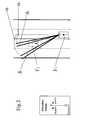
- FIG. 1 and FIG. 2 illustrated traffic situation
- two motor vehicles F1, F2 meet on a road with two lanes in each direction.
- the two motor vehicles F1, F2 are on the left driving stiffeners on the road.
- the motor vehicle F1 is equipped with a camera K with which the traffic situation lying in front of the motor vehicle F1 can be detected.
- the image of the traffic situation recorded by the camera K is evaluated by a device designed for this purpose and not described in greater detail.
- the light sources identified as relevant for setting the vertical light-dark boundaries are determined.
- the object angles ⁇ 1, ⁇ 2 between the longitudinal direction of the motor vehicle F1 and the light sources identified as relevant are determined.
- the information about the object angles ⁇ 1, ⁇ 2 are transmitted to a control unit for controlling the headlights with trackable vertical cut-offs.
- the control unit determines from the object angles ⁇ 1, ⁇ 2 the light-dark limits of the light distribution to be set.
- the light-dark boundaries are placed in the direction of the object angles ⁇ 1, ⁇ 2.
- the bright-dark boundaries do not have to lie in the direction of the object angles ⁇ 1, ⁇ 2, if this makes sense, for example, for journeys along curvy sections.
- the opening angle ⁇ is determined from the object angles ⁇ 1, ⁇ 2.
- the left object angle ⁇ 1 is subtracted from the right object angle ⁇ 2.
- the opening angle ⁇ is determined from this a positive size.
- This angular advance ⁇ 1, ⁇ 2 is in the example of FIG. 2 taken into account for defining the vertical light-dark boundaries.
- the left cut-off will be opposite the FIG. 1 to the angle ⁇ 1 to the left and the right-hand light-dark border is compared to the FIG. 1 shifted by the angle ⁇ 2 to the right.
Abstract
Description
Die Erfindung betrifft ein Steuergerät zur Steuerung von Fahrzeugscheinwerfern zum Erzeugen einer Lichtverteilung mit nachführbaren vertikalen Hell-Dunkel-Grenzen zum Entblenden von vorrausfahrenden oder entgegenkommenden Fahrzeugen,
- mit einem Eingang zum Einlesen von Objektwinkeln des zu entblendenden Fahrzeugs oder eines Bildsignals der vor dem Kraftfahrzeug liegenden Verkehrssituation, aus dem durch ein Mittel zum Ermitteln von Objektwinkeln des Steuergeräts Objektwinkel des zu entblendenden Fahrzeugs ermittelbar sind,
- mit einem Mittel zum Ermitteln von vertikalen Hell-Dunkel-Grenzen,
- mit einem Mittel zum Erzeugen von Stellsignalen zum Einstellen der Hell-Dunkel-Grenzen der Lichtverteilung und
- mit einem oder mehreren Ausgängen, über die die Stellsignale an die Fahrzeugscheinwerfer bzw. an Stellmittel der Fahrzeugscheinwerfer übermittelbar sind.
- with an input for reading in object angles of the vehicle to be glazed or an image signal of the traffic situation lying ahead of the motor vehicle, from which object angle of the vehicle to be glazed can be determined by a means for determining object angles of the control device,
- with a means of determining vertical cut-offs,
- with a means for generating actuating signals for setting the light-dark limits of the light distribution and
- with one or more outputs, via which the control signals can be transmitted to the vehicle headlights or to adjusting means of the vehicle headlights.
Aus dem Stand der Technik sind verschiedene Fahrzeuge mit Scheinwerfern bekannt, bei denen die vertikale Hell-Dunkel-Grenze zum Entblenden von vorrausfahrenden oder entgegenkommenden Fahrzeugen eingestellt werden kann. Dazu werden ein rechter und ein linker Objektwinkel bestimmt. Die Objektwinkel beziehen sich auf die äußerst links und die äußerst rechts erkannte(n) und als relevant eingestufte(n) Lichtquelle(n) eines zu entblendenden Fahrzeugs. Die vertikalen Hell-Dunkel-Grenzen der Lichtverteilung werden entsprechend der Objektwinkel eingestellt. Wenn sich die Lage der als relevant eingestuften Lichtquellen während der Fahrt ändert, ändert sich der entsprechende Objektwinkel. Dann werden die vertikalen Hell-Dunkel-Grenzen entsprechend den Objektwinkeln nachgeführt. Dazu sind die bekannten Steuergeräte zur Steuerung von Fahrzeugscheinwerfern zum Erzeugen einer Lichtverteilung mit nachführbaren vertikalen Hell-Dunkel-Grenzen eingerichtet.Various vehicles with headlamps are known from the prior art, in which the vertical cut-off line can be set to de-dazzle oncoming or oncoming vehicles. For this purpose, a right and a left object angle are determined. The object angles refer to the light source (s) of a vehicle to be blinded, which are identified on the extreme left and the extreme right and are classified as relevant. The vertical light-dark limits of the light distribution are adjusted according to the object angle. If the position of the light sources classified as relevant changes while driving, the corresponding object angle changes. Then the vertical light-dark boundaries are tracked according to the object angles. For this purpose, the known control devices for controlling vehicle headlights for generating a light distribution with trackable vertical cut-off lines are set up.
Die Nachführung der vertikalen Hell-Dunkel-Grenzen erfolgt bei den bekannten Sytemen aufgrund von technisch bedingten Verzögerungen oder Totzeiten nicht zeitgleich zur Änderung der Objektwinkel. Zu Verzögerungen oder Totzeiten kann es zum Beispiel durch Sensoren, Aktoren, Regler bzw. Steuereinheiten und Signalwege kommen. Wenn sich die Objektwinkel sehr schnell ändern, kann dies zur Folge haben, dass die Nachführung so langsam ist, dass eine ausreichende Entblendung nicht mehr erfolgt.The tracking of the vertical light-dark boundaries in the known systems due to technical delays or dead times not at the same time to change the object angle. Delays or dead times can occur, for example, through sensors, actuators, controllers or control units and signal paths. If the object angles change very quickly, the result may be that the tracking is so slow that sufficient glare no longer occurs.
Außerdem können sich Toleranzen der Sensoren oder Regler negativ auf die Nachführung der vertikalen Hell-Dunkel-Grenzen auswirken. Auch die Toleranzen können sich dahingehend bemerkbar machen, dass eine ausreichende Entblendung nicht mehr erfolgt.In addition, tolerances of the sensors or controllers may adversely affect the tracking of the vertical cut-offs. The tolerances can also be noticeable to the effect that a sufficient glare no longer occurs.
Hier setzt die vorliegende Erfindung an.This is where the present invention begins.
Der vorliegenden Erfindung liegt das Problem zugrunde, ein Steuergerät der eingangs genannten Art zu fortzubilden, dass es trotz der Verzögerungen, Totzeiten und/oder Toleranzen für eine ausreichende Entblendung der vorrausfahrenden oder entgegenkommenden Fahrzeuge sorgen kann.The present invention is based on the problem, a control unit of the type mentioned in that it can provide despite the delays, dead times and / or tolerances for a sufficient glare the vorrausfahrenden or oncoming vehicles.
Dieses Problem wird erfindungsgemäß dadurch gelöst, dass mittels des Mittels zum Ermitteln der vertikalen Hell-Dunkel-Grenzen jede einstellbare vertikale Hell-Dunkel-Grenze in Abhängigkeit eines der genannten Objektwinkel und eines Winkelvorhalts ermittelbar ist. Durch den Winkelvorhalt ist es möglich, dass die tatsächlichen, aktuell vorliegenden Objektwinkel von den der Einstellung der Hell-Dunkel-Grenze zugrunde liegendenden vergangenen Objektwinkel abweichen, ohne dass es zu einer Blendung der vorrausfahrenden oder entgegenkommenden Fahrzeuge kommt. Der Winkelvorhalt ist vorzugsweise stets positiv und wird zu den ermittelten oder eingelesenen Objektwinkeln hinzuaddiert (rechter Objektwinkel) oder abgezogen (linker Objektwinkel).This problem is inventively solved in that by means of the means for determining the vertical light-dark boundaries each adjustable vertical cut-off in light of a specified object angle and an angle prediction can be determined. Due to the angular advance, it is possible for the actual, currently present object angles to deviate from the past object angles on which the setting of the cut-off line is based, without dazzling the vehicles ahead or oncoming vehicles. The angle derivative is preferably always positive and is added to the determined or read object angles (right object angle) or subtracted (left object angle).
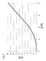
Der Winkelvorhalt kann vorzugsweise in Abhängigkeit der Differenz zwischen zwei Objektwinkeln, d. h. dem sogenannten Öffnungswinkel des zu entblendenden Bereichs einstellbar sein.The angle lead may preferably depend on the difference between two object angles, i. H. be adjustable to the so-called opening angle of the area to be blended.
Wahlweise oder ergänzend kann der Winkelvorhalt in Abhängigkeit
- von der Relativgeschwindigkeit des Kraftfahrzeuges und des zu entblendenden Fahrzeugs,
- von der Entfernung zwischen dem Kraftfahrzeug und dem zu entblendenden Fahrzeug,
- von der zeitlichen Änderung wenigstens eines Objektwinkels,
- vom Objektwinkel,
- von der Fahrtrichtung des zu entblendenden Fahrzeugs zum Kraftfahrzeug einstellbar sein.
- from the relative speed of the motor vehicle and the vehicle to be blinded,
- the distance between the motor vehicle and the vehicle to be blinded,
- from the temporal change of at least one object angle,
- from the object angle,
- be adjustable from the direction of travel of the vehicle to be blinded to the motor vehicle.
Ein erfindungsgemäßes Steuergerät kann so ausgestaltet sein, dass der Winkelvorhalt mittels wenigstens einer Gleichung durch das Mittel zum Ermitteln berechenbar ist. Ebenso ist es möglich, dass der Winkelvorhalt mittels wenigstens einer Zuordnungsvorschrift durch das Mittel zum Ermitteln ermittelbar ist. Die Zuordnungsvorschrift kann sich aus einer Tabelle ergeben.A control unit according to the invention can be designed such that the angular advance can be calculated by means of at least one equation by the means for determining. It is also possible that the angle derivative can be determined by means of at least one assignment rule by the means for determining. The assignment rule can result from a table.
Es ist möglich, dass der Betrag des Winkelvorhalts begrenzt ist und einen vorgegebenen Wert nicht übersteigt.It is possible that the amount of the angle precedence is limited and does not exceed a predetermined value.
Anhand der beigefügten Zeichnungen wird die Erfindung nachfolgend näher erläutert. Dabei zeigt:
- Fig. 1
- eine schematische Darstellung einer Verkehrssituation in der Draufsicht, wie sie bei einem Kraftfahrzeug mit einem Steuergerät zur Steuerung von Fahrzeugscheinwerfern zum Erzeugen einer Lichtverteilung mit nachführ- baren vertikalen Hell-Dunkel-Grenzen nach dem Stand der Technik ent- stehen kann,
- Fig. 2
- eine der in
Fig. 1 dargestellten entsprechenden Verkehrsituation, wie sie bei einem Kraftfahrzeug mit einem erfindungsgemäßen Steuergerät ent- stehen kann, und - Fig. 3
- eine Darstellung einer Zuordnung des Winkelvorhalts zu Objektwinkeln.
- Fig. 1
- a schematic representation of a traffic situation in plan view, as may arise in a motor vehicle with a control device for controlling vehicle headlights for generating a light distribution with traceable vertical light-dark boundaries according to the prior art,
- Fig. 2
- one of the in
Fig. 1 illustrated corresponding traffic situation, as they are in a motor vehicle with a control device according to the invention can stand, and - Fig. 3
- a representation of an assignment of the angle lead to object angles.
In der in
Das von der Kamera K aufgenommene Bild der Verkehrssituation wird von einer dazu eingerichteten, nicht näher beschriebenen Vorrichtung ausgewertet. Dabei werden die für das Einstellen der vertikalen Hell-Dunkel-Grenzen als relevant erkannten Lichtquellen festgestellt. Außerdem werden die Objektwinkel α1, α2 zwischen der Längsrichtung des Kraftfahrzeuges F1 und den als relevant erkannten Lichtquellen ermittelt. Die Informationen über die Objektwinkel α1, α2 werden an ein Steuergerät zur Steuerung der Scheinwerfer mit nachführbaren vertikalen Hell-Dunkel-Grenzen übermittelt. Das Steuergerät ermittelt aus den Objektwinkeln α1, α2 die einzustellenden Hell-Dunkel-Grenzen der Lichtverteilung.The image of the traffic situation recorded by the camera K is evaluated by a device designed for this purpose and not described in greater detail. In the process, the light sources identified as relevant for setting the vertical light-dark boundaries are determined. In addition, the object angles α1, α2 between the longitudinal direction of the motor vehicle F1 and the light sources identified as relevant are determined. The information about the object angles α1, α2 are transmitted to a control unit for controlling the headlights with trackable vertical cut-offs. The control unit determines from the object angles α1, α2 the light-dark limits of the light distribution to be set.
Im Beispiel der
Im erfindungsgemäßen Steuergerät wird aus den Objektwinkeln α1, α2 der Öffnungswinkel β bestimmt. Dazu wird der linke Objektwinkel α1 vom rechten Objektwinkel α2 subtrahiert. Unter Beachtung der in der
Dieser Winkelvorhalt δ1, δ2 wird im Beispiel der
- F1F1
- Kraftfahrzeug mit Einstellung der Hell-Dunkel-GrenzenMotor vehicle with adjustment of the cut-off lines
- F2F2
- zu entblendendes Kraftfahrzeugto be blinded motor vehicle
- KK
- Kameracamera
- α1α1
- linker Objektwinkelleft object angle
- α2α2
- rechter Objektwinkelright object angle
- ββ
- Winkelvorhaltangle derivative
- δ1δ1
- Linker WinkelvorhaltLeft angle lead
- δ2δ2
- Rechter WinkelvorhaltRight angle lead
Claims (10)
mit einem Eingang zum Einlesen von Objektwinkeln (α1,α2) des zu entblendenden Fahrzeugs (F2) oder eines Bildsignals der vor dem Kraftfahrzeug liegenden Verkehrssituation, aus dem durch ein Mittel zum Ermitteln von Objektwinkeln (α1, α2) des Steuergeräts Objektwinkel (α1, α2) des zu entblendenden Fahrzeugs ermittelbar sind,
mit einem Mittel zum Ermitteln von vertikalen Hell-Dunkel-Grenzen,
mit einem Mittel zum Erzeugen von Stellsignalen zum Einstellen der Hell-Dunkel-Grenzen und
mit einem oder mehreren Ausgängen, über die die Stellsignale an die Fahrzeugscheinwerfer bzw. an Stellmittel der Fahrzeugscheinwerfer übermittelbar sind,
dadurch gekennzeichnet, dass
mittels des Mittels zum Ermitteln der vertikalen Hell-Dunkel-Grenzen jede einstellbare vertikale Hell-Dunkel-Grenze in Abhängigkeit eines der Objektwinkel (α1, α2) und eines Winkelvorhalts (δ1, δ2) ermittelbar ist.Control unit for controlling headlamps of a motor vehicle (F1) for generating a light distribution with trackable vertical cut-off lines for fading out ahead or oncoming vehicles (F2),
with an input for reading in object angles (α1, α2) of the vehicle to be dazzled (F2) or an image signal of the traffic situation ahead of the motor vehicle, from which by means of determining object angles (α1, α2) of the control device object angles (α1, α2 ) of the vehicle to be blinded can be determined,
with a means of determining vertical cut-offs,
with a means for generating control signals for setting the light-dark boundaries and
with one or more outputs, via which the control signals can be transmitted to the vehicle headlights or to adjusting means of the vehicle headlights,
characterized in that
By means of the means for determining the vertical light-dark boundaries each adjustable vertical cut-off in light of one of the object angle (α1, α2) and an angle (δ1, δ2) can be determined.
Priority Applications (1)
| Application Number | Priority Date | Filing Date | Title |
|---|---|---|---|
| EP20090177967 EP2338731B1 (en) | 2009-12-04 | 2009-12-04 | Control device for controlling vehicle headlights to generate a light distribution with trackable vertical bright-dark boundaries |
Applications Claiming Priority (1)
| Application Number | Priority Date | Filing Date | Title |
|---|---|---|---|
| EP20090177967 EP2338731B1 (en) | 2009-12-04 | 2009-12-04 | Control device for controlling vehicle headlights to generate a light distribution with trackable vertical bright-dark boundaries |
Publications (2)
| Publication Number | Publication Date |
|---|---|
| EP2338731A1 true EP2338731A1 (en) | 2011-06-29 |
| EP2338731B1 EP2338731B1 (en) | 2014-09-03 |
Family
ID=41725658
Family Applications (1)
| Application Number | Title | Priority Date | Filing Date |
|---|---|---|---|
| EP20090177967 Active EP2338731B1 (en) | 2009-12-04 | 2009-12-04 | Control device for controlling vehicle headlights to generate a light distribution with trackable vertical bright-dark boundaries |
Country Status (1)
| Country | Link |
|---|---|
| EP (1) | EP2338731B1 (en) |
Cited By (10)
| Publication number | Priority date | Publication date | Assignee | Title |
|---|---|---|---|---|
| JP2013043623A (en) * | 2011-08-26 | 2013-03-04 | Stanley Electric Co Ltd | Lighting control device of vehicle headlamp, and vehicle headlamp system |
| EP2639105A1 (en) * | 2010-11-12 | 2013-09-18 | Toyota Jidosha Kabushiki Kaisha | Vehicular light distribution control system and vehicular light distribution control method |
| EP2700537A1 (en) * | 2012-08-21 | 2014-02-26 | Koito Manufacturing Co., Ltd. | Lamp control system and control device |
| DE102012109068A1 (en) * | 2012-09-26 | 2014-06-12 | Hella Kgaa Hueck & Co. | Method for controlling positioning velocity of vertical light-dark boundary relative to light function of object in vehicle, involves adjusting positioning velocity of vertical light-dark boundary to determined rate of change of object |
| JPWO2013080363A1 (en) * | 2011-12-01 | 2015-04-27 | トヨタ自動車株式会社 | Vehicle light distribution control system |
| FR3031480A1 (en) * | 2015-01-12 | 2016-07-15 | Valeo Schalter & Sensoren Gmbh | METHOD FOR ADJUSTING A PROJECTOR OF A MOTOR VEHICLE, DEVICE FOR ADJUSTING SUCH A PROJECTOR, AND MOTOR VEHICLE COMPRISING SUCH A DEVICE |
| CN110901514A (en) * | 2019-11-28 | 2020-03-24 | 北京海纳川汽车部件股份有限公司 | Vehicle and control method and device of high beam thereof |
| CN110979161A (en) * | 2019-12-30 | 2020-04-10 | 北京海纳川汽车部件股份有限公司 | Control method and system of vehicle lamp and vehicle |
| EP3693218A1 (en) * | 2011-09-06 | 2020-08-12 | Koito Manufacturing Co., Ltd. | Vehicle headlamp apparatus and system vehicle headlamp system |
| WO2021228385A1 (en) * | 2020-05-13 | 2021-11-18 | HELLA GmbH & Co. KGaA | Method for controlling a headlamp of a motor vehicle |
Families Citing this family (1)
| Publication number | Priority date | Publication date | Assignee | Title |
|---|---|---|---|---|
| JP5752552B2 (en) * | 2011-10-05 | 2015-07-22 | スタンレー電気株式会社 | Light distribution control device for vehicle lamp, light distribution control system for vehicle lamp |
Citations (7)
| Publication number | Priority date | Publication date | Assignee | Title |
|---|---|---|---|---|
| EP1780462A1 (en) * | 2005-10-25 | 2007-05-02 | Valeo Vision | Process for modulated illumination of a road and headlamp using this process |
| DE102008014082A1 (en) | 2007-03-13 | 2008-09-18 | Mitsubishi Jidosha Kogyo K.K. | Cable connection structure in electric vehicles |
| DE102007040042A1 (en) | 2007-08-24 | 2009-02-26 | Hella Kgaa Hueck & Co. | System for generating a light beam in the apron of a motor vehicle |
| DE102008060949A1 (en) | 2008-12-06 | 2009-09-17 | Daimler Ag | Method for controlling vehicle headlamps, involves dividing surrounding into multiple areas outside vehicle, and unrestricted upper beam distribution is adjusted, if no other road user is identified in areas |
| DE102008014182A1 (en) * | 2008-03-14 | 2009-09-17 | Daimler Ag | Method for driving light control of a vehicle |
| EP2116421A2 (en) | 2008-05-08 | 2009-11-11 | Koito Manufacturing Co., Ltd. | Automotive headlamp apparatus |
| DE102008025808A1 (en) | 2008-05-29 | 2009-12-03 | Hella Kgaa Hueck & Co. | Controller for adjusting e.g. light distribution, of main headlights of motor vehicle, has control unit for adjusting vertical light/dark boundary to compensate delays between time points of measuring object angle and control signals |
-
2009
- 2009-12-04 EP EP20090177967 patent/EP2338731B1/en active Active
Patent Citations (7)
| Publication number | Priority date | Publication date | Assignee | Title |
|---|---|---|---|---|
| EP1780462A1 (en) * | 2005-10-25 | 2007-05-02 | Valeo Vision | Process for modulated illumination of a road and headlamp using this process |
| DE102008014082A1 (en) | 2007-03-13 | 2008-09-18 | Mitsubishi Jidosha Kogyo K.K. | Cable connection structure in electric vehicles |
| DE102007040042A1 (en) | 2007-08-24 | 2009-02-26 | Hella Kgaa Hueck & Co. | System for generating a light beam in the apron of a motor vehicle |
| DE102008014182A1 (en) * | 2008-03-14 | 2009-09-17 | Daimler Ag | Method for driving light control of a vehicle |
| EP2116421A2 (en) | 2008-05-08 | 2009-11-11 | Koito Manufacturing Co., Ltd. | Automotive headlamp apparatus |
| DE102008025808A1 (en) | 2008-05-29 | 2009-12-03 | Hella Kgaa Hueck & Co. | Controller for adjusting e.g. light distribution, of main headlights of motor vehicle, has control unit for adjusting vertical light/dark boundary to compensate delays between time points of measuring object angle and control signals |
| DE102008060949A1 (en) | 2008-12-06 | 2009-09-17 | Daimler Ag | Method for controlling vehicle headlamps, involves dividing surrounding into multiple areas outside vehicle, and unrestricted upper beam distribution is adjusted, if no other road user is identified in areas |
Cited By (13)
| Publication number | Priority date | Publication date | Assignee | Title |
|---|---|---|---|---|
| US8972117B2 (en) | 2010-11-12 | 2015-03-03 | Toyota Jidosha Kabushiki Kaisha | Vehicular light distribution control system and vehicular light distribution control method |
| EP2639105A1 (en) * | 2010-11-12 | 2013-09-18 | Toyota Jidosha Kabushiki Kaisha | Vehicular light distribution control system and vehicular light distribution control method |
| EP2639105A4 (en) * | 2010-11-12 | 2014-04-30 | Toyota Motor Co Ltd | Vehicular light distribution control system and vehicular light distribution control method |
| JP2013043623A (en) * | 2011-08-26 | 2013-03-04 | Stanley Electric Co Ltd | Lighting control device of vehicle headlamp, and vehicle headlamp system |
| EP3693218A1 (en) * | 2011-09-06 | 2020-08-12 | Koito Manufacturing Co., Ltd. | Vehicle headlamp apparatus and system vehicle headlamp system |
| JPWO2013080363A1 (en) * | 2011-12-01 | 2015-04-27 | トヨタ自動車株式会社 | Vehicle light distribution control system |
| US9163801B2 (en) | 2012-08-21 | 2015-10-20 | Koito Manufacturing Co., Ltd. | Lamp control system and control device |
| EP2700537A1 (en) * | 2012-08-21 | 2014-02-26 | Koito Manufacturing Co., Ltd. | Lamp control system and control device |
| DE102012109068A1 (en) * | 2012-09-26 | 2014-06-12 | Hella Kgaa Hueck & Co. | Method for controlling positioning velocity of vertical light-dark boundary relative to light function of object in vehicle, involves adjusting positioning velocity of vertical light-dark boundary to determined rate of change of object |
| FR3031480A1 (en) * | 2015-01-12 | 2016-07-15 | Valeo Schalter & Sensoren Gmbh | METHOD FOR ADJUSTING A PROJECTOR OF A MOTOR VEHICLE, DEVICE FOR ADJUSTING SUCH A PROJECTOR, AND MOTOR VEHICLE COMPRISING SUCH A DEVICE |
| CN110901514A (en) * | 2019-11-28 | 2020-03-24 | 北京海纳川汽车部件股份有限公司 | Vehicle and control method and device of high beam thereof |
| CN110979161A (en) * | 2019-12-30 | 2020-04-10 | 北京海纳川汽车部件股份有限公司 | Control method and system of vehicle lamp and vehicle |
| WO2021228385A1 (en) * | 2020-05-13 | 2021-11-18 | HELLA GmbH & Co. KGaA | Method for controlling a headlamp of a motor vehicle |
Also Published As
| Publication number | Publication date |
|---|---|
| EP2338731B1 (en) | 2014-09-03 |
Similar Documents
| Publication | Publication Date | Title |
|---|---|---|
| EP2338731B1 (en) | Control device for controlling vehicle headlights to generate a light distribution with trackable vertical bright-dark boundaries | |
| EP2156983B1 (en) | Method and device for controlling the vertical cut-off line of headlamps | |
| EP2156984B1 (en) | Method and device for controlling the vertical cut-off line of headlamps | |
| DE112013003278T5 (en) | Vehicle headlamp light distribution control apparatus | |
| EP2294380A1 (en) | Method for detecting misalignment of a vehicle headlight using a camera | |
| DE102012209043B4 (en) | vehicle headlight device | |
| DE102011083265B4 (en) | Method and driver assistance device for determining the presence of a structural separation between two lanes | |
| DE102008025459A1 (en) | Method and device for calibrating a vertical light-dark boundary generated by a headlight of a vehicle | |
| DE102014018995A1 (en) | Method for operating a headlight and motor vehicle headlights | |
| EP2119592A1 (en) | Control device to control vehicle's main headlights | |
| DE102014204791A1 (en) | Automatic control of the headlights of a vehicle | |
| DE102008025808B4 (en) | Control device for setting a light distribution and a vertical light-dark boundary of one or more main headlights of a first motor vehicle in the event of delays in the generation of control signals | |
| EP2119593A1 (en) | Control device to control and/or regulate a vertical cut-off line for a vehicle's headlights | |
| DE102013109071A1 (en) | Arrangement and method for blinding vehicles with the aid of at least one near field sensor device | |
| DE102012002333A1 (en) | Method for controlling optical axis of beam of headlight distribution of vehicle, involves directing optical axis of beam as warning function to border lane boundary, when lane boundary is exceeded | |
| DE102016208831B4 (en) | Method and device for driving light control | |
| EP2576290B1 (en) | Control unit and method for preventing dazzling of vehicles during turning manoeuvres | |
| EP2123512B1 (en) | Control device to control and/or to command a vertical cut-off line | |
| DE102012110594A1 (en) | Method for controlling remote light for vehicle, has control unit connected to sensor system for controlling main beam, where control unit outputs signal for deactivating driving beam in response to detection of overhauling vehicle | |
| DE102009031805A1 (en) | Method for detecting objects in surrounding of vehicle, involves periodically determining yaw angle of vehicle, periodically determining change of yaw angle, and determining and correcting angle changes of object angle | |
| DE102014009252A1 (en) | Motor vehicle and method for providing a static crossing light | |
| DE102014006598A1 (en) | Method for operating a driver assistance system of a motor vehicle, driver assistance system and motor vehicle | |
| DE102013212011A1 (en) | Method for controlling the light of a vehicle | |
| DE102012014300A1 (en) | Method for recognizing object e.g. tree in environment of car, involves assigning objects based on object attribute to object class and adjusting operating condition of vehicle based on assignment of object to object class | |
| DE102011050532B4 (en) | Control device and method for controlling vehicle headlights |
Legal Events
| Date | Code | Title | Description |
|---|---|---|---|
| PUAI | Public reference made under article 153(3) epc to a published international application that has entered the european phase |
Free format text: ORIGINAL CODE: 0009012 |
|
| AK | Designated contracting states |
Kind code of ref document: A1 Designated state(s): AT BE BG CH CY CZ DE DK EE ES FI FR GB GR HR HU IE IS IT LI LT LU LV MC MK MT NL NO PL PT RO SE SI SK SM TR |
|
| AX | Request for extension of the european patent |
Extension state: AL BA RS |
|
| 17P | Request for examination filed |
Effective date: 20120328 |
|
| 17Q | First examination report despatched |
Effective date: 20120427 |
|
| GRAP | Despatch of communication of intention to grant a patent |
Free format text: ORIGINAL CODE: EPIDOSNIGR1 |
|
| INTG | Intention to grant announced |
Effective date: 20140425 |
|
| GRAS | Grant fee paid |
Free format text: ORIGINAL CODE: EPIDOSNIGR3 |
|
| GRAA | (expected) grant |
Free format text: ORIGINAL CODE: 0009210 |
|
| AK | Designated contracting states |
Kind code of ref document: B1 Designated state(s): AT BE BG CH CY CZ DE DK EE ES FI FR GB GR HR HU IE IS IT LI LT LU LV MC MK MT NL NO PL PT RO SE SI SK SM TR |
|
| REG | Reference to a national code |
Ref country code: GB Ref legal event code: FG4D Free format text: NOT ENGLISH |
|
| REG | Reference to a national code |
Ref country code: AT Ref legal event code: REF Ref document number: 685395 Country of ref document: AT Kind code of ref document: T Effective date: 20140915 Ref country code: CH Ref legal event code: EP |
|
| REG | Reference to a national code |
Ref country code: IE Ref legal event code: FG4D Free format text: LANGUAGE OF EP DOCUMENT: GERMAN |
|
| REG | Reference to a national code |
Ref country code: DE Ref legal event code: R096 Ref document number: 502009009887 Country of ref document: DE Effective date: 20141016 |
|
| PG25 | Lapsed in a contracting state [announced via postgrant information from national office to epo] |
Ref country code: LT Free format text: LAPSE BECAUSE OF FAILURE TO SUBMIT A TRANSLATION OF THE DESCRIPTION OR TO PAY THE FEE WITHIN THE PRESCRIBED TIME-LIMIT Effective date: 20140903 Ref country code: FI Free format text: LAPSE BECAUSE OF FAILURE TO SUBMIT A TRANSLATION OF THE DESCRIPTION OR TO PAY THE FEE WITHIN THE PRESCRIBED TIME-LIMIT Effective date: 20140903 Ref country code: ES Free format text: LAPSE BECAUSE OF FAILURE TO SUBMIT A TRANSLATION OF THE DESCRIPTION OR TO PAY THE FEE WITHIN THE PRESCRIBED TIME-LIMIT Effective date: 20140903 Ref country code: GR Free format text: LAPSE BECAUSE OF FAILURE TO SUBMIT A TRANSLATION OF THE DESCRIPTION OR TO PAY THE FEE WITHIN THE PRESCRIBED TIME-LIMIT Effective date: 20141204 Ref country code: NO Free format text: LAPSE BECAUSE OF FAILURE TO SUBMIT A TRANSLATION OF THE DESCRIPTION OR TO PAY THE FEE WITHIN THE PRESCRIBED TIME-LIMIT Effective date: 20141203 Ref country code: SE Free format text: LAPSE BECAUSE OF FAILURE TO SUBMIT A TRANSLATION OF THE DESCRIPTION OR TO PAY THE FEE WITHIN THE PRESCRIBED TIME-LIMIT Effective date: 20140903 |
|
| REG | Reference to a national code |
Ref country code: NL Ref legal event code: VDEP Effective date: 20140903 |
|
| REG | Reference to a national code |
Ref country code: LT Ref legal event code: MG4D |
|
| PG25 | Lapsed in a contracting state [announced via postgrant information from national office to epo] |
Ref country code: HR Free format text: LAPSE BECAUSE OF FAILURE TO SUBMIT A TRANSLATION OF THE DESCRIPTION OR TO PAY THE FEE WITHIN THE PRESCRIBED TIME-LIMIT Effective date: 20140903 Ref country code: CY Free format text: LAPSE BECAUSE OF FAILURE TO SUBMIT A TRANSLATION OF THE DESCRIPTION OR TO PAY THE FEE WITHIN THE PRESCRIBED TIME-LIMIT Effective date: 20140903 Ref country code: LV Free format text: LAPSE BECAUSE OF FAILURE TO SUBMIT A TRANSLATION OF THE DESCRIPTION OR TO PAY THE FEE WITHIN THE PRESCRIBED TIME-LIMIT Effective date: 20140903 |
|
| PG25 | Lapsed in a contracting state [announced via postgrant information from national office to epo] |
Ref country code: NL Free format text: LAPSE BECAUSE OF FAILURE TO SUBMIT A TRANSLATION OF THE DESCRIPTION OR TO PAY THE FEE WITHIN THE PRESCRIBED TIME-LIMIT Effective date: 20140903 |
|
| PG25 | Lapsed in a contracting state [announced via postgrant information from national office to epo] |
Ref country code: SK Free format text: LAPSE BECAUSE OF FAILURE TO SUBMIT A TRANSLATION OF THE DESCRIPTION OR TO PAY THE FEE WITHIN THE PRESCRIBED TIME-LIMIT Effective date: 20140903 Ref country code: IS Free format text: LAPSE BECAUSE OF FAILURE TO SUBMIT A TRANSLATION OF THE DESCRIPTION OR TO PAY THE FEE WITHIN THE PRESCRIBED TIME-LIMIT Effective date: 20150103 Ref country code: CZ Free format text: LAPSE BECAUSE OF FAILURE TO SUBMIT A TRANSLATION OF THE DESCRIPTION OR TO PAY THE FEE WITHIN THE PRESCRIBED TIME-LIMIT Effective date: 20140903 Ref country code: EE Free format text: LAPSE BECAUSE OF FAILURE TO SUBMIT A TRANSLATION OF THE DESCRIPTION OR TO PAY THE FEE WITHIN THE PRESCRIBED TIME-LIMIT Effective date: 20140903 Ref country code: RO Free format text: LAPSE BECAUSE OF FAILURE TO SUBMIT A TRANSLATION OF THE DESCRIPTION OR TO PAY THE FEE WITHIN THE PRESCRIBED TIME-LIMIT Effective date: 20140903 Ref country code: PT Free format text: LAPSE BECAUSE OF FAILURE TO SUBMIT A TRANSLATION OF THE DESCRIPTION OR TO PAY THE FEE WITHIN THE PRESCRIBED TIME-LIMIT Effective date: 20150105 |
|
| PG25 | Lapsed in a contracting state [announced via postgrant information from national office to epo] |
Ref country code: PL Free format text: LAPSE BECAUSE OF FAILURE TO SUBMIT A TRANSLATION OF THE DESCRIPTION OR TO PAY THE FEE WITHIN THE PRESCRIBED TIME-LIMIT Effective date: 20140903 |
|
| REG | Reference to a national code |
Ref country code: DE Ref legal event code: R097 Ref document number: 502009009887 Country of ref document: DE |
|
| PG25 | Lapsed in a contracting state [announced via postgrant information from national office to epo] |
Ref country code: BE Free format text: LAPSE BECAUSE OF NON-PAYMENT OF DUE FEES Effective date: 20141231 |
|
| PLBE | No opposition filed within time limit |
Free format text: ORIGINAL CODE: 0009261 |
|
| STAA | Information on the status of an ep patent application or granted ep patent |
Free format text: STATUS: NO OPPOSITION FILED WITHIN TIME LIMIT |
|
| PG25 | Lapsed in a contracting state [announced via postgrant information from national office to epo] |
Ref country code: LU Free format text: LAPSE BECAUSE OF FAILURE TO SUBMIT A TRANSLATION OF THE DESCRIPTION OR TO PAY THE FEE WITHIN THE PRESCRIBED TIME-LIMIT Effective date: 20141204 Ref country code: DK Free format text: LAPSE BECAUSE OF FAILURE TO SUBMIT A TRANSLATION OF THE DESCRIPTION OR TO PAY THE FEE WITHIN THE PRESCRIBED TIME-LIMIT Effective date: 20140903 |
|
| REG | Reference to a national code |
Ref country code: CH Ref legal event code: PL |
|
| 26N | No opposition filed |
Effective date: 20150604 |
|
| PG25 | Lapsed in a contracting state [announced via postgrant information from national office to epo] |
Ref country code: IT Free format text: LAPSE BECAUSE OF FAILURE TO SUBMIT A TRANSLATION OF THE DESCRIPTION OR TO PAY THE FEE WITHIN THE PRESCRIBED TIME-LIMIT Effective date: 20140903 |
|
| REG | Reference to a national code |
Ref country code: IE Ref legal event code: MM4A |
|
| PG25 | Lapsed in a contracting state [announced via postgrant information from national office to epo] |
Ref country code: LI Free format text: LAPSE BECAUSE OF NON-PAYMENT OF DUE FEES Effective date: 20141231 Ref country code: CH Free format text: LAPSE BECAUSE OF NON-PAYMENT OF DUE FEES Effective date: 20141231 Ref country code: IE Free format text: LAPSE BECAUSE OF NON-PAYMENT OF DUE FEES Effective date: 20141204 |
|
| REG | Reference to a national code |
Ref country code: FR Ref legal event code: PLFP Year of fee payment: 7 |
|
| PG25 | Lapsed in a contracting state [announced via postgrant information from national office to epo] |
Ref country code: SI Free format text: LAPSE BECAUSE OF FAILURE TO SUBMIT A TRANSLATION OF THE DESCRIPTION OR TO PAY THE FEE WITHIN THE PRESCRIBED TIME-LIMIT Effective date: 20140903 |
|
| REG | Reference to a national code |
Ref country code: AT Ref legal event code: MM01 Ref document number: 685395 Country of ref document: AT Kind code of ref document: T Effective date: 20141204 |
|
| PG25 | Lapsed in a contracting state [announced via postgrant information from national office to epo] |
Ref country code: SM Free format text: LAPSE BECAUSE OF FAILURE TO SUBMIT A TRANSLATION OF THE DESCRIPTION OR TO PAY THE FEE WITHIN THE PRESCRIBED TIME-LIMIT Effective date: 20140903 |
|
| PG25 | Lapsed in a contracting state [announced via postgrant information from national office to epo] |
Ref country code: AT Free format text: LAPSE BECAUSE OF NON-PAYMENT OF DUE FEES Effective date: 20141204 Ref country code: MC Free format text: LAPSE BECAUSE OF FAILURE TO SUBMIT A TRANSLATION OF THE DESCRIPTION OR TO PAY THE FEE WITHIN THE PRESCRIBED TIME-LIMIT Effective date: 20140903 |
|
| PG25 | Lapsed in a contracting state [announced via postgrant information from national office to epo] |
Ref country code: BG Free format text: LAPSE BECAUSE OF FAILURE TO SUBMIT A TRANSLATION OF THE DESCRIPTION OR TO PAY THE FEE WITHIN THE PRESCRIBED TIME-LIMIT Effective date: 20140903 |
|
| PG25 | Lapsed in a contracting state [announced via postgrant information from national office to epo] |
Ref country code: TR Free format text: LAPSE BECAUSE OF FAILURE TO SUBMIT A TRANSLATION OF THE DESCRIPTION OR TO PAY THE FEE WITHIN THE PRESCRIBED TIME-LIMIT Effective date: 20140903 Ref country code: MT Free format text: LAPSE BECAUSE OF FAILURE TO SUBMIT A TRANSLATION OF THE DESCRIPTION OR TO PAY THE FEE WITHIN THE PRESCRIBED TIME-LIMIT Effective date: 20140903 Ref country code: HU Free format text: LAPSE BECAUSE OF FAILURE TO SUBMIT A TRANSLATION OF THE DESCRIPTION OR TO PAY THE FEE WITHIN THE PRESCRIBED TIME-LIMIT; INVALID AB INITIO Effective date: 20091204 |
|
| REG | Reference to a national code |
Ref country code: FR Ref legal event code: PLFP Year of fee payment: 8 |
|
| REG | Reference to a national code |
Ref country code: FR Ref legal event code: PLFP Year of fee payment: 9 |
|
| REG | Reference to a national code |
Ref country code: DE Ref legal event code: R081 Ref document number: 502009009887 Country of ref document: DE Owner name: HELLA GMBH & CO. KGAA, DE Free format text: FORMER OWNER: HELLA KGAA HUECK & CO., 59557 LIPPSTADT, DE |
|
| PG25 | Lapsed in a contracting state [announced via postgrant information from national office to epo] |
Ref country code: MK Free format text: LAPSE BECAUSE OF FAILURE TO SUBMIT A TRANSLATION OF THE DESCRIPTION OR TO PAY THE FEE WITHIN THE PRESCRIBED TIME-LIMIT Effective date: 20140903 |
|
| REG | Reference to a national code |
Ref country code: FR Ref legal event code: PLFP Year of fee payment: 10 |
|
| PGFP | Annual fee paid to national office [announced via postgrant information from national office to epo] |
Ref country code: FR Payment date: 20230929 Year of fee payment: 15 |
|
| PGFP | Annual fee paid to national office [announced via postgrant information from national office to epo] |
Ref country code: GB Payment date: 20231012 Year of fee payment: 15 |
|
| PGFP | Annual fee paid to national office [announced via postgrant information from national office to epo] |
Ref country code: DE Payment date: 20231010 Year of fee payment: 15 |