EP2338708A1 - Tandem suspension system for a vehicle, with pivot integrated in the vehicle frame - Google Patents
Tandem suspension system for a vehicle, with pivot integrated in the vehicle frame Download PDFInfo
- Publication number
- EP2338708A1 EP2338708A1 EP09425533A EP09425533A EP2338708A1 EP 2338708 A1 EP2338708 A1 EP 2338708A1 EP 09425533 A EP09425533 A EP 09425533A EP 09425533 A EP09425533 A EP 09425533A EP 2338708 A1 EP2338708 A1 EP 2338708A1
- Authority
- EP
- European Patent Office
- Prior art keywords
- support
- pivot
- leaf spring
- vehicle
- tandem suspension
- Prior art date
- Legal status (The legal status is an assumption and is not a legal conclusion. Google has not performed a legal analysis and makes no representation as to the accuracy of the status listed.)
- Granted
Links
- 239000000725 suspension Substances 0.000 title claims abstract description 32
- 238000012423 maintenance Methods 0.000 description 3
- 238000005096 rolling process Methods 0.000 description 3
- 229910001018 Cast iron Inorganic materials 0.000 description 2
- 238000009434 installation Methods 0.000 description 2
- 238000004519 manufacturing process Methods 0.000 description 2
- 239000000463 material Substances 0.000 description 2
- 230000002787 reinforcement Effects 0.000 description 2
- 238000010276 construction Methods 0.000 description 1
- 238000005516 engineering process Methods 0.000 description 1
- 238000012856 packing Methods 0.000 description 1
Images


Classifications
-
- B—PERFORMING OPERATIONS; TRANSPORTING
- B60—VEHICLES IN GENERAL
- B60G—VEHICLE SUSPENSION ARRANGEMENTS
- B60G5/00—Resilient suspensions for a set of tandem wheels or axles having interrelated movements
- B60G5/02—Resilient suspensions for a set of tandem wheels or axles having interrelated movements mounted on a single pivoted arm, e.g. the arm being rigid
- B60G5/03—Resilient suspensions for a set of tandem wheels or axles having interrelated movements mounted on a single pivoted arm, e.g. the arm being rigid the arm itself being resilient, e.g. a leafspring
-
- B—PERFORMING OPERATIONS; TRANSPORTING
- B60—VEHICLES IN GENERAL
- B60G—VEHICLE SUSPENSION ARRANGEMENTS
- B60G2202/00—Indexing codes relating to the type of spring, damper or actuator
- B60G2202/10—Type of spring
- B60G2202/11—Leaf spring
- B60G2202/112—Leaf spring longitudinally arranged
-
- B—PERFORMING OPERATIONS; TRANSPORTING
- B60—VEHICLES IN GENERAL
- B60G—VEHICLE SUSPENSION ARRANGEMENTS
- B60G2204/00—Indexing codes related to suspensions per se or to auxiliary parts
- B60G2204/10—Mounting of suspension elements
- B60G2204/12—Mounting of springs or dampers
- B60G2204/121—Mounting of leaf springs
-
- B—PERFORMING OPERATIONS; TRANSPORTING
- B60—VEHICLES IN GENERAL
- B60G—VEHICLE SUSPENSION ARRANGEMENTS
- B60G2204/00—Indexing codes related to suspensions per se or to auxiliary parts
- B60G2204/40—Auxiliary suspension parts; Adjustment of suspensions
- B60G2204/43—Fittings, brackets or knuckles
- B60G2204/4302—Fittings, brackets or knuckles for fixing suspension arm on the vehicle body or chassis
Definitions
- the present invention relates to a tandem suspension system for a vehicle, with pivot integrated in the vehicle frame.
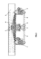
- a tandem suspension system known in the art is shown for example in figures 1 and 2.1 , respectively in a side and in a cross view.
- the system allows the suspension of two axles 1, 2, possibly both being driving axles, and is connected to the side members 3 of the vehicle.
- a bearing structure 4 called “vertical elongated arm”, projecting from the lower part of the side member, from which the pivot 5 of the suspension projects, in a position underneath the side member.
- a leaf spring package 6 is fixed on the pivot 5 by means of a pair of U bolts 7, so that it can oscillate around the pivot. The ends of the leaf spring package engage the vehicle axles, determining its suspension.
- a pair of reaction rods 8 are hinged to, and connect in an oscillating way, the axles of the vehicle 1, 2 to the lower end of the vertical elongated arm 4.
- the oscillating structure of the tandem suspension rotates around the pivot fixed to the vertical elongated arm, from which it projects.
- the oscillating part is mounted on the projecting part of the pivot with respect to the vertical elongated arm that, in its turn, is fixed under the side member.
- the structure is very heavy, because of both the vertical elongated arm bearing structure, which is made of cast iron, and the pivot, which needs to have a considerable diameter, since it is a projecting part. This determines an increase of the vehicle's weight to the detriment of its carrying capacity.
- the shape of the vertical elongated arm is not suitable for reacting to the longitudinal loads transmitted to the reaction rods.
- the aim of the present invention is to provide a tandem suspension with the pivot integrated in the frame of a vehicle, and vehicle comprising said suspension, suitable for overcoming all the drawbacks mentioned above.
- the subject of the present invention is a tandem suspension for two vehicle axles, comprising at least a leaf spring for each side of the vehicle, said leaf spring being connected in its middle part to a support, while its ends are connected to said axles, characterized in that at each one of the sides of the vehicle said support is laterally and externally connected to a side member of the vehicle frame, and includes a pivot to which the leaf spring is connected centrally and the bottom, in a horizontally pivoted way, the pivot being placed at the side of the side member, leaning against both ends on the support.
- the subject of the present invention is in particular to a tandem suspension with the pivot integrated in the frame of a vehicle, and vehicle comprising said suspension, as described more fully in the claims, which are an integral part of this description.
- Figures from 2.2 to 8 show examples of tandem suspensions according to the present invention.
- a side member 21 is shown having a reinforcement cross member 22.
- the support preferably comprises reinforcement elongated arms 25 and has a semi-cilindrical shape, open at the bottom. The support and the pivot are positioned laterally to the side member, within its width.
- the lower shape of the latter is such as to adapt to the upper surface of the leaf spring packet, preferably flattened, with a pair of side wings 28 which extend by projecting with respect to the middle part 29 having a hollow cylinder shape, so that it can internally house the pivot.
- the side wings comprise an upper cavity.
- a pair of bush bearings 30, 31, preferably of the sliding type, are driven into the ends of the pivot 24, and are placed between the pivot and the internal surface of the middle part 29 of the oscillating support.
- the bearings also have side shoulders 44, 45, in order to seal to the borders of the oscillating support.
- a cap 32 externally covers the support, and comprises an internal cavity 33 where the external end of the pivot 24 is housed along with the bush bearing 31. The other internal end 34 of the pivot 24 is fixed into the support 23.
- the leaf spring packet 26 is fixed to the horizontally pivoted support 27 by means of a pair of U bolts 35, 36 whose upper end is housed in the corresponding cavity of the wings 28.
- the U bolts 35, 36 are tighten to the leaf spring packet by a screwing on a plate 37 which closes the lower part of the leaf spring packet.
- a support for the reaction rods is provided and consists of a pair of V-shaped tubulars 38, 39, connected to the lower part of the side member 21, in order to obtain a triangle, which closes on a lower support 40, suitable to house the oscillating pivots of the reaction rods 41, 42.
- the reaction rod support is independent and is separate from the suspension system.
- the other ends of the reaction rods 41, 42 are fixed to the axles 43, 44 of the vehicle, as well as the ends of the leaf spring package.
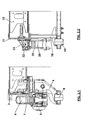
- Figures 7 shows an example of the application of the tandem suspension system according to the invention to a leaf spring package of the parabolic type 50.
- the support 23 is fixed in the lower part of the side member side 21.
- the lowered position of the support is possible since the parabolic leaves of the package may be shaped during the manufacturing in order to raise the ends, and also the package has a limited thickness.
- Figures 8 shows an example of the application of the tandem suspension system according to the invention to a leaf spring package of the semi-elliptical type 51.
- the support 23 is fixed to the upper part of the side of the side member 21, in order compensate the higher thickness of the leaf spring package with respect to the previous case.
- the pivot is simple and light, and it is not projecting, but it rests also on its front part, therefore behaving like a beam supported at both ends.
- the bearings consist of bushes of the sliding type, made of self-lubricating, sintered, very hard materials, being less thick than the bearings used in the systems known (e.g. from 160mm to 55mm).
- the support of the reaction rods has a structure independent from the suspension, which is very light, for example made of tubular.
- the support of the pivot can be opened.
- the pivot is driven into the support from behind.
- the support may be made of cast iron and is external bench mounted, off line, before the installation on the frame, which reduces maintenance costs, because, in case an intervention is needed, it is enough to remove the cap and to the oscillating support off, which is integral with the leaf spring. Therefore, if it is necessary to dismantle the leaf spring, it is enough to intervene on the support.
- the leaf spring rests under the pivot, thus the support with the pivot bears the vehicle's weight.
- the U bolts are used just for packing the leaf spring, their function is no longer to hold the whole vehicle. The advantage of increasing the safety and reducing the weight of the whole system is evident.
- the U bolts may have just the function of tightening the spring to the oscillating support, but it has no longer the function to bear the weight of the whole vehicle load, as in the system of the type known in the art.
- the U bolts may have a smaller diameter, being also more reliable.
- the pivot integrated in the support uses a double support, while the pivot of the system known in the art, being a projecting part, uses a single support. This allows a considerable reduction of the dimensions of the pivot, with the same vehicle load.
- the support of the pivot made of two parts can be easily assembled to the oscillating support, to which the sliding bearings have previously been added, by driving them into it.
- the support, along with the pivot and the oscillating support, is then assembled to the frame in its different positions, as a function of its usage with parabolic or with semi-elliptical springs. During the maintenance it is possible to replace the sliding bearings without dismantling the pivot support from the frame.
- the support of the reaction rods having just the function of fixing them, unlike the support of the system known in the art, which also has to support the pivot, may be realized by means of a simplified technology.
Landscapes
- Engineering & Computer Science (AREA)
- Mechanical Engineering (AREA)
- Vehicle Body Suspensions (AREA)
Abstract
Description
- The present invention relates to a tandem suspension system for a vehicle, with pivot integrated in the vehicle frame.
- A tandem suspension system known in the art is shown for example in
figures 1 and2.1 , respectively in a side and in a cross view. - The system allows the suspension of two
axles 1, 2, possibly both being driving axles, and is connected to the side members 3 of the vehicle. According to the system, on each side of the vehicle there is a bearing structure 4 called "vertical elongated arm", projecting from the lower part of the side member, from which thepivot 5 of the suspension projects, in a position underneath the side member. Aleaf spring package 6 is fixed on thepivot 5 by means of a pair of U bolts 7, so that it can oscillate around the pivot. The ends of the leaf spring package engage the vehicle axles, determining its suspension. A pair ofreaction rods 8 are hinged to, and connect in an oscillating way, the axles of thevehicle 1, 2 to the lower end of the vertical elongated arm 4. - Thus the leaf spring packages are in a higher position, over the pivot, in order to limit the height of the frame from the ground, which should be kept as low as possible for improving vehicle stability and vehicle bodying. The oscillating structure of the tandem suspension (or equalizer suspension) rotates around the pivot fixed to the vertical elongated arm, from which it projects. The oscillating part is mounted on the projecting part of the pivot with respect to the vertical elongated arm that, in its turn, is fixed under the side member.
- A series of drawbacks are present in a structure known of this type.
- The structure is very heavy, because of both the vertical elongated arm bearing structure, which is made of cast iron, and the pivot, which needs to have a considerable diameter, since it is a projecting part. This determines an increase of the vehicle's weight to the detriment of its carrying capacity. The shape of the vertical elongated arm is not suitable for reacting to the longitudinal loads transmitted to the reaction rods.
- Thus the vehicle is suspended from the U bolts, which as a matter of fact bear the weight of the whole vehicle by means of the leaf spring, generating a structural weak point.
- Therefore the aim of the present invention is to provide a tandem suspension with the pivot integrated in the frame of a vehicle, and vehicle comprising said suspension, suitable for overcoming all the drawbacks mentioned above.
- The subject of the present invention is a tandem suspension for two vehicle axles, comprising at least a leaf spring for each side of the vehicle, said leaf spring being connected in its middle part to a support, while its ends are connected to said axles, characterized in that at each one of the sides of the vehicle said support is laterally and externally connected to a side member of the vehicle frame, and includes a pivot to which the leaf spring is connected centrally and the bottom, in a horizontally pivoted way, the pivot being placed at the side of the side member, leaning against both ends on the support.
- The subject of the present invention is in particular to a tandem suspension with the pivot integrated in the frame of a vehicle, and vehicle comprising said suspension, as described more fully in the claims, which are an integral part of this description.
- Further purposes and advantages of the present invention will become clear from the following detailed description of a preferred embodiment (and relative alternative embodiments) and the drawings that are attached hereto, which are merely illustrative and non-limitative, in which:
-
figures 1 and2.1 , show a tandem suspension system of the type known in the art, respectively according to a side view and to a cross view; -
figures 2.2 shows a tandem suspension system that is subject of the invention, according to a cross view; -
figures 3 and4 show an exploded view of the parts of the system infig. 2.2 , according to respectively a top and a bottom view; -
figures 5 and6 , show the system offigure 2.2 , respectively according to a side view and to a cross section view and to a bottom view; -
figures 7 and 8 show two application examples of the tandem suspension system according to the invention in case of respectively a leaf spring package of the parabolic type and of the semi-elliptical type. - In the drawings the same reference numbers and letters identify the same elements or components.
- Figures from 2.2 to 8 show examples of tandem suspensions according to the present invention.
- In the figures a
side member 21 is shown having areinforcement cross member 22. On the lateral external part of theside member 21, asupport 23, internally housing apivot 24, is fixed by bolting. The support preferably comprises reinforcementelongated arms 25 and has a semi-cilindrical shape, open at the bottom. The support and the pivot are positioned laterally to the side member, within its width. - A
leaf spring packet 26, comprising a series of stacked leaf springs, of any number, is fixed to thepivot 24, underneath both the pivot and thesupport 23, by means of anoscillating support 27. The lower shape of the latter is such as to adapt to the upper surface of the leaf spring packet, preferably flattened, with a pair ofside wings 28 which extend by projecting with respect to themiddle part 29 having a hollow cylinder shape, so that it can internally house the pivot. The side wings comprise an upper cavity. - A pair of
bush bearings pivot 24, and are placed between the pivot and the internal surface of themiddle part 29 of the oscillating support. Preferably the bearings also haveside shoulders - A
cap 32 externally covers the support, and comprises aninternal cavity 33 where the external end of thepivot 24 is housed along with the bush bearing 31. The otherinternal end 34 of thepivot 24 is fixed into thesupport 23. - The
leaf spring packet 26 is fixed to the horizontallypivoted support 27 by means of a pair ofU bolts wings 28. TheU bolts plate 37 which closes the lower part of the leaf spring packet. - A support for the reaction rods is provided and consists of a pair of V-
shaped tubulars side member 21, in order to obtain a triangle, which closes on alower support 40, suitable to house the oscillating pivots of thereaction rods reaction rods axles -
Figures 7 shows an example of the application of the tandem suspension system according to the invention to a leaf spring package of theparabolic type 50. In this case thesupport 23 is fixed in the lower part of theside member side 21. The lowered position of the support is possible since the parabolic leaves of the package may be shaped during the manufacturing in order to raise the ends, and also the package has a limited thickness. Thus it is possible to lift the connection points of the tandem axles to the ends, and to limit the height of the frame to the ground. -
Figures 8 shows an example of the application of the tandem suspension system according to the invention to a leaf spring package of thesemi-elliptical type 51. In this case thesupport 23 is fixed to the upper part of the side of theside member 21, in order compensate the higher thickness of the leaf spring package with respect to the previous case. Also in this case it is possible to shape the semi-elliptical leaves of the package during the manufacturing, in order to raise the connection points of the tandem axles to the ends and to limit the height of the frame to the ground. - In the system according to the invention, the pivot is simple and light, and it is not projecting, but it rests also on its front part, therefore behaving like a beam supported at both ends.
- On the contrary, in the system known an internal end of the pivot is stuck to the vertical elongated arm and projects towards the outside. This means that the support projects from the side member, but the pivot does not.
- In the system according to the invention, the bearings consist of bushes of the sliding type, made of self-lubricating, sintered, very hard materials, being less thick than the bearings used in the systems known (e.g. from 160mm to 55mm).
- Actually it is not necessary to use rolling bearings, since the leaf spring package and the oscillating support only oscillate (e.g. ± 7°) around the pivot, thus avoiding to use the expensive rolling bearings. The invention, however, does not prevent the usage of rolling bearings.
- The support of the reaction rods has a structure independent from the suspension, which is very light, for example made of tubular.
- During the installation, the support of the pivot can be opened. The pivot is driven into the support from behind. The support may be made of cast iron and is external bench mounted, off line, before the installation on the frame, which reduces maintenance costs, because, in case an intervention is needed, it is enough to remove the cap and to the oscillating support off, which is integral with the leaf spring. Therefore, if it is necessary to dismantle the leaf spring, it is enough to intervene on the support.
- The leaf spring rests under the pivot, thus the support with the pivot bears the vehicle's weight. The U bolts are used just for packing the leaf spring, their function is no longer to hold the whole vehicle. The advantage of increasing the safety and reducing the weight of the whole system is evident.
- It will be apparent to the person skilled in the art that further alternative and equivalent embodiments of the invention can be conceived and reduced to practice without departing from the scope of the invention.
- The advantages deriving from the use of this invention are evident.
- The positioning of the pivot over the springs allows the U bolts to have just the function of tightening the spring to the oscillating support, but it has no longer the function to bear the weight of the whole vehicle load, as in the system of the type known in the art. Thus the U bolts may have a smaller diameter, being also more reliable.
- The pivot integrated in the support uses a double support, while the pivot of the system known in the art, being a projecting part, uses a single support. This allows a considerable reduction of the dimensions of the pivot, with the same vehicle load.
- Using sliding bearings allows a reduction of the dimensions, of the maintenance operations, along with a higher reliability.
- The support of the pivot made of two parts can be easily assembled to the oscillating support, to which the sliding bearings have previously been added, by driving them into it. The support, along with the pivot and the oscillating support, is then assembled to the frame in its different positions, as a function of its usage with parabolic or with semi-elliptical springs. During the maintenance it is possible to replace the sliding bearings without dismantling the pivot support from the frame.
- The support of the reaction rods, having just the function of fixing them, unlike the support of the system known in the art, which also has to support the pivot, may be realized by means of a simplified technology.
- The reduction of the weight with respect to the tandem suspension of the type known in the art is considerable (e.g. about 50%), without using any special material. This also allows to increase the payload of the vehicle.
- From the description set forth above it will be possible for the person skilled in the art to embody the invention with no need of describing further construction details.
Claims (9)
- Tandem suspension for vehicle with at least two axles, comprising at least a leaf spring for each side of the vehicle, said leaf spring being connected in its middle part to a support, while its ends are connected to said axles, characterized in that at each one of the sides of the vehicle said support (23) is laterally and externally connected to a side member (21) of the vehicle frame, and includes a pivot (24) to which the leaf spring is connected centrally and at the bottom, in a horizontally pivoted way, the pivot being placed at the side of the side member, leaning against both ends on the support.
- Tandem suspension according to the claim 1, wherein the bottom of the support has an open shape and the leaf spring (26) is fixed to the pivot (24), underneath both the pivot and the support (23), by means of an oscillating support.
- Tandem suspension according to claim 1, wherein the lower shape of said oscillating support (26) is such as to adapt to the upper surface of the leaf spring, and comprises a pair of side wings (28) which extend by projecting with respect to the middle part (29) having a hollow cylinder shape, so that it can internally house the pivot.
- Tandem suspension according to claim 3, further comprising:- at least a pair of bush bearings (30, 31) driven into the ends of the pivot (24), and placed between the pivot and the internal surface of the middle part (29) of the oscillating support;- at least a cap (32) suitable for externally closing the support, the cap comprising a compartment for the external end of the pivot, with its respective bush bearing, the other internal end (34) of the pivot being driven into the support.
- Tandem suspension according to claim 3, further comprising a pair of U bolts (35, 36) suitable to fix the leaf spring (26) to the oscillating support (27), the upper end of the U bolt being housed in said side wings (28).
- Tandem suspension according to claim 1, wherein said leaf spring is a leaf spring package of the parabolic type (50), and wherein the support (23) is fixed to the lower part of the side of the side member (21).
- Tandem suspension according to claim 1, wherein said leaf spring is a leaf spring package of the semi-elliptical type (51), and wherein the support (23) is fixed to the upper part of the side of the side member (21).
- Vehicle comprising a tandem suspension according to any of the previous claims.
- Vehicle according to claim 8, comprising a support for reaction rods connected to said two axles, said support being connected to the lower part of the side member (21), in an independent and separate way from said tandem suspension.
Priority Applications (4)
| Application Number | Priority Date | Filing Date | Title |
|---|---|---|---|
| EP09425533.8A EP2338708B1 (en) | 2009-12-24 | 2009-12-24 | Tandem suspension system for a vehicle, with pivot integrated in the vehicle frame |
| ES09425533.8T ES2457191T3 (en) | 2009-12-24 | 2009-12-24 | Tandem suspension system for a vehicle with pivot integrated in the vehicle chassis |
| CN201010600462.9A CN102107596B (en) | 2009-12-24 | 2010-12-22 | Tandem suspension system for a vehicle, with pivot integrated in the vehicle frame |
| BRPI1013451-4A BRPI1013451B1 (en) | 2009-12-24 | 2010-12-24 | tandem axle suspension system for a vehicle, with pivot integrated into the vehicle chassis |
Applications Claiming Priority (1)
| Application Number | Priority Date | Filing Date | Title |
|---|---|---|---|
| EP09425533.8A EP2338708B1 (en) | 2009-12-24 | 2009-12-24 | Tandem suspension system for a vehicle, with pivot integrated in the vehicle frame |
Publications (2)
| Publication Number | Publication Date |
|---|---|
| EP2338708A1 true EP2338708A1 (en) | 2011-06-29 |
| EP2338708B1 EP2338708B1 (en) | 2014-01-15 |
Family
ID=42169505
Family Applications (1)
| Application Number | Title | Priority Date | Filing Date |
|---|---|---|---|
| EP09425533.8A Not-in-force EP2338708B1 (en) | 2009-12-24 | 2009-12-24 | Tandem suspension system for a vehicle, with pivot integrated in the vehicle frame |
Country Status (4)
| Country | Link |
|---|---|
| EP (1) | EP2338708B1 (en) |
| CN (1) | CN102107596B (en) |
| BR (1) | BRPI1013451B1 (en) |
| ES (1) | ES2457191T3 (en) |
Families Citing this family (1)
| Publication number | Priority date | Publication date | Assignee | Title |
|---|---|---|---|---|
| CN102582390B (en) * | 2012-03-02 | 2014-05-28 | 潍柴动力股份有限公司 | Balancing suspension and automobile applying same |
Citations (6)
| Publication number | Priority date | Publication date | Assignee | Title |
|---|---|---|---|---|
| DE434162C (en) * | 1925-04-29 | 1926-09-22 | Int Motor Co | Suspension for vehicles with double axles |
| US2002152A (en) * | 1933-10-23 | 1935-05-21 | Nelson Le Moon Truck Company | Axle mounting |
| DE1047033B (en) * | 1954-11-12 | 1958-12-18 | Daimler Benz Ag | Suspension of double rigid rear axles |
| FR1296474A (en) * | 1960-08-08 | 1962-06-15 | Eaton Mfg Co | Suspension device for vehicles |
| DE4309004A1 (en) * | 1993-03-20 | 1994-09-22 | Man Nutzfahrzeuge Ag | Link-guided tandem axle assembly |
| WO2003072377A1 (en) * | 2002-02-28 | 2003-09-04 | Volvo Lastvagnar Ab | Conical rubber bearing |
-
2009
- 2009-12-24 EP EP09425533.8A patent/EP2338708B1/en not_active Not-in-force
- 2009-12-24 ES ES09425533.8T patent/ES2457191T3/en active Active
-
2010
- 2010-12-22 CN CN201010600462.9A patent/CN102107596B/en not_active Expired - Fee Related
- 2010-12-24 BR BRPI1013451-4A patent/BRPI1013451B1/en not_active IP Right Cessation
Patent Citations (6)
| Publication number | Priority date | Publication date | Assignee | Title |
|---|---|---|---|---|
| DE434162C (en) * | 1925-04-29 | 1926-09-22 | Int Motor Co | Suspension for vehicles with double axles |
| US2002152A (en) * | 1933-10-23 | 1935-05-21 | Nelson Le Moon Truck Company | Axle mounting |
| DE1047033B (en) * | 1954-11-12 | 1958-12-18 | Daimler Benz Ag | Suspension of double rigid rear axles |
| FR1296474A (en) * | 1960-08-08 | 1962-06-15 | Eaton Mfg Co | Suspension device for vehicles |
| DE4309004A1 (en) * | 1993-03-20 | 1994-09-22 | Man Nutzfahrzeuge Ag | Link-guided tandem axle assembly |
| WO2003072377A1 (en) * | 2002-02-28 | 2003-09-04 | Volvo Lastvagnar Ab | Conical rubber bearing |
Also Published As
| Publication number | Publication date |
|---|---|
| EP2338708B1 (en) | 2014-01-15 |
| CN102107596A (en) | 2011-06-29 |
| CN102107596B (en) | 2014-12-17 |
| BRPI1013451A2 (en) | 2016-01-26 |
| ES2457191T3 (en) | 2014-04-25 |
| BRPI1013451B1 (en) | 2020-10-20 |
Similar Documents
| Publication | Publication Date | Title |
|---|---|---|
| CA2836136C (en) | Height control valve assembly for axle/suspension systems | |
| US9073400B2 (en) | Motor vehicle multi-link suspension system including a transverse leaf spring | |
| US20090033141A1 (en) | Powered motor vehicle rear axle of a twist-beam axle type | |
| CN201086615Y (en) | Breaking type balancing suspension rack and heavy-duty truck with the same | |
| MX2015001582A (en) | Motor vehicle axle suspension with longitudinal leaf spring. | |
| US20190061847A1 (en) | Tandem lift auxiliary axle assembly | |
| CN107264219A (en) | A kind of mine car rear suspension assembly | |
| EP1901931A1 (en) | Rubber spring for a vehicle wheel axle suspension | |
| EP2338708B1 (en) | Tandem suspension system for a vehicle, with pivot integrated in the vehicle frame | |
| CN206983662U (en) | A kind of mine car rear suspension assembly | |
| CN209920975U (en) | Air bag full-bearing air suspension structure | |
| ES2959605T3 (en) | Spring blade for a crossbow | |
| CN202071656U (en) | Suspension device for mining vehicle | |
| CN102275478A (en) | Suspension system for mine trucks | |
| CN104773044A (en) | Hanging device for low-speed traction vehicle | |
| US20170051520A1 (en) | Vehicle-mounted concrete pump | |
| US9527357B2 (en) | Trunnion suspension structure | |
| US20070052195A1 (en) | Light truck support lift | |
| CN203835166U (en) | Self-balancing locomotive cab interior vertical movable side window | |
| CN205871667U (en) | Balanced axle suspension frame assembly | |
| CN202847369U (en) | Hanging bracket component, hanging bracket with hanging bracket component and vehicle with hanging bracket | |
| CN107199840A (en) | A kind of air suspension trailing arm | |
| CN105857002B (en) | Individual wheel suspension with air spring element for a rear axle of a vehicle and correspondingly equipped rear axle of a vehicle | |
| EP2380761A1 (en) | Fastening assembly for connecting a wheel suspension to a vehicle frame | |
| RU2834094C1 (en) | Buffer assembly, suspension mechanism and vehicle |
Legal Events
| Date | Code | Title | Description |
|---|---|---|---|
| PUAI | Public reference made under article 153(3) epc to a published international application that has entered the european phase |
Free format text: ORIGINAL CODE: 0009012 |
|
| AK | Designated contracting states |
Kind code of ref document: A1 Designated state(s): AT BE BG CH CY CZ DE DK EE ES FI FR GB GR HR HU IE IS IT LI LT LU LV MC MK MT NL NO PL PT RO SE SI SK SM TR |
|
| AX | Request for extension of the european patent |
Extension state: AL BA RS |
|
| 17P | Request for examination filed |
Effective date: 20111223 |
|
| 17Q | First examination report despatched |
Effective date: 20120329 |
|
| GRAP | Despatch of communication of intention to grant a patent |
Free format text: ORIGINAL CODE: EPIDOSNIGR1 |
|
| GRAS | Grant fee paid |
Free format text: ORIGINAL CODE: EPIDOSNIGR3 |
|
| GRAP | Despatch of communication of intention to grant a patent |
Free format text: ORIGINAL CODE: EPIDOSNIGR1 |
|
| GRAA | (expected) grant |
Free format text: ORIGINAL CODE: 0009210 |
|
| INTG | Intention to grant announced |
Effective date: 20131126 |
|
| AK | Designated contracting states |
Kind code of ref document: B1 Designated state(s): AT BE BG CH CY CZ DE DK EE ES FI FR GB GR HR HU IE IS IT LI LT LU LV MC MK MT NL NO PL PT RO SE SI SK SM TR |
|
| REG | Reference to a national code |
Ref country code: GB Ref legal event code: FG4D Ref country code: CH Ref legal event code: EP |
|
| REG | Reference to a national code |
Ref country code: AT Ref legal event code: REF Ref document number: 649650 Country of ref document: AT Kind code of ref document: T Effective date: 20140215 |
|
| REG | Reference to a national code |
Ref country code: IE Ref legal event code: FG4D |
|
| REG | Reference to a national code |
Ref country code: DE Ref legal event code: R096 Ref document number: 602009021435 Country of ref document: DE Effective date: 20140227 |
|
| REG | Reference to a national code |
Ref country code: CH Ref legal event code: NV Representative=s name: N&G PATENT SERVICES SA, CH |
|
| REG | Reference to a national code |
Ref country code: SE Ref legal event code: TRGR |
|
| REG | Reference to a national code |
Ref country code: NL Ref legal event code: T3 |
|
| REG | Reference to a national code |
Ref country code: ES Ref legal event code: FG2A Ref document number: 2457191 Country of ref document: ES Kind code of ref document: T3 Effective date: 20140425 |
|
| REG | Reference to a national code |
Ref country code: AT Ref legal event code: MK05 Ref document number: 649650 Country of ref document: AT Kind code of ref document: T Effective date: 20140115 |
|
| REG | Reference to a national code |
Ref country code: LT Ref legal event code: MG4D |
|
| PG25 | Lapsed in a contracting state [announced via postgrant information from national office to epo] |
Ref country code: LT Free format text: LAPSE BECAUSE OF FAILURE TO SUBMIT A TRANSLATION OF THE DESCRIPTION OR TO PAY THE FEE WITHIN THE PRESCRIBED TIME-LIMIT Effective date: 20140115 Ref country code: NO Free format text: LAPSE BECAUSE OF FAILURE TO SUBMIT A TRANSLATION OF THE DESCRIPTION OR TO PAY THE FEE WITHIN THE PRESCRIBED TIME-LIMIT Effective date: 20140415 Ref country code: IS Free format text: LAPSE BECAUSE OF FAILURE TO SUBMIT A TRANSLATION OF THE DESCRIPTION OR TO PAY THE FEE WITHIN THE PRESCRIBED TIME-LIMIT Effective date: 20140515 |
|
| PG25 | Lapsed in a contracting state [announced via postgrant information from national office to epo] |
Ref country code: FI Free format text: LAPSE BECAUSE OF FAILURE TO SUBMIT A TRANSLATION OF THE DESCRIPTION OR TO PAY THE FEE WITHIN THE PRESCRIBED TIME-LIMIT Effective date: 20140115 Ref country code: PT Free format text: LAPSE BECAUSE OF FAILURE TO SUBMIT A TRANSLATION OF THE DESCRIPTION OR TO PAY THE FEE WITHIN THE PRESCRIBED TIME-LIMIT Effective date: 20140515 Ref country code: AT Free format text: LAPSE BECAUSE OF FAILURE TO SUBMIT A TRANSLATION OF THE DESCRIPTION OR TO PAY THE FEE WITHIN THE PRESCRIBED TIME-LIMIT Effective date: 20140115 Ref country code: CY Free format text: LAPSE BECAUSE OF FAILURE TO SUBMIT A TRANSLATION OF THE DESCRIPTION OR TO PAY THE FEE WITHIN THE PRESCRIBED TIME-LIMIT Effective date: 20140115 |
|
| PG25 | Lapsed in a contracting state [announced via postgrant information from national office to epo] |
Ref country code: BE Free format text: LAPSE BECAUSE OF FAILURE TO SUBMIT A TRANSLATION OF THE DESCRIPTION OR TO PAY THE FEE WITHIN THE PRESCRIBED TIME-LIMIT Effective date: 20140115 Ref country code: HR Free format text: LAPSE BECAUSE OF FAILURE TO SUBMIT A TRANSLATION OF THE DESCRIPTION OR TO PAY THE FEE WITHIN THE PRESCRIBED TIME-LIMIT Effective date: 20140115 Ref country code: LV Free format text: LAPSE BECAUSE OF FAILURE TO SUBMIT A TRANSLATION OF THE DESCRIPTION OR TO PAY THE FEE WITHIN THE PRESCRIBED TIME-LIMIT Effective date: 20140115 |
|
| REG | Reference to a national code |
Ref country code: DE Ref legal event code: R097 Ref document number: 602009021435 Country of ref document: DE |
|
| PG25 | Lapsed in a contracting state [announced via postgrant information from national office to epo] |
Ref country code: DK Free format text: LAPSE BECAUSE OF FAILURE TO SUBMIT A TRANSLATION OF THE DESCRIPTION OR TO PAY THE FEE WITHIN THE PRESCRIBED TIME-LIMIT Effective date: 20140115 Ref country code: RO Free format text: LAPSE BECAUSE OF FAILURE TO SUBMIT A TRANSLATION OF THE DESCRIPTION OR TO PAY THE FEE WITHIN THE PRESCRIBED TIME-LIMIT Effective date: 20140115 Ref country code: EE Free format text: LAPSE BECAUSE OF FAILURE TO SUBMIT A TRANSLATION OF THE DESCRIPTION OR TO PAY THE FEE WITHIN THE PRESCRIBED TIME-LIMIT Effective date: 20140115 Ref country code: CZ Free format text: LAPSE BECAUSE OF FAILURE TO SUBMIT A TRANSLATION OF THE DESCRIPTION OR TO PAY THE FEE WITHIN THE PRESCRIBED TIME-LIMIT Effective date: 20140115 |
|
| PLBE | No opposition filed within time limit |
Free format text: ORIGINAL CODE: 0009261 |
|
| STAA | Information on the status of an ep patent application or granted ep patent |
Free format text: STATUS: NO OPPOSITION FILED WITHIN TIME LIMIT |
|
| PG25 | Lapsed in a contracting state [announced via postgrant information from national office to epo] |
Ref country code: SK Free format text: LAPSE BECAUSE OF FAILURE TO SUBMIT A TRANSLATION OF THE DESCRIPTION OR TO PAY THE FEE WITHIN THE PRESCRIBED TIME-LIMIT Effective date: 20140115 Ref country code: PL Free format text: LAPSE BECAUSE OF FAILURE TO SUBMIT A TRANSLATION OF THE DESCRIPTION OR TO PAY THE FEE WITHIN THE PRESCRIBED TIME-LIMIT Effective date: 20140115 |
|
| 26N | No opposition filed |
Effective date: 20141016 |
|
| REG | Reference to a national code |
Ref country code: DE Ref legal event code: R097 Ref document number: 602009021435 Country of ref document: DE Effective date: 20141016 |
|
| PG25 | Lapsed in a contracting state [announced via postgrant information from national office to epo] |
Ref country code: SI Free format text: LAPSE BECAUSE OF FAILURE TO SUBMIT A TRANSLATION OF THE DESCRIPTION OR TO PAY THE FEE WITHIN THE PRESCRIBED TIME-LIMIT Effective date: 20140115 |
|
| PG25 | Lapsed in a contracting state [announced via postgrant information from national office to epo] |
Ref country code: LU Free format text: LAPSE BECAUSE OF FAILURE TO SUBMIT A TRANSLATION OF THE DESCRIPTION OR TO PAY THE FEE WITHIN THE PRESCRIBED TIME-LIMIT Effective date: 20141224 |
|
| REG | Reference to a national code |
Ref country code: IE Ref legal event code: MM4A |
|
| PG25 | Lapsed in a contracting state [announced via postgrant information from national office to epo] |
Ref country code: IE Free format text: LAPSE BECAUSE OF NON-PAYMENT OF DUE FEES Effective date: 20141224 |
|
| REG | Reference to a national code |
Ref country code: FR Ref legal event code: PLFP Year of fee payment: 7 |
|
| PG25 | Lapsed in a contracting state [announced via postgrant information from national office to epo] |
Ref country code: SM Free format text: LAPSE BECAUSE OF FAILURE TO SUBMIT A TRANSLATION OF THE DESCRIPTION OR TO PAY THE FEE WITHIN THE PRESCRIBED TIME-LIMIT Effective date: 20140115 |
|
| PG25 | Lapsed in a contracting state [announced via postgrant information from national office to epo] |
Ref country code: MC Free format text: LAPSE BECAUSE OF FAILURE TO SUBMIT A TRANSLATION OF THE DESCRIPTION OR TO PAY THE FEE WITHIN THE PRESCRIBED TIME-LIMIT Effective date: 20140115 |
|
| PG25 | Lapsed in a contracting state [announced via postgrant information from national office to epo] |
Ref country code: BG Free format text: LAPSE BECAUSE OF FAILURE TO SUBMIT A TRANSLATION OF THE DESCRIPTION OR TO PAY THE FEE WITHIN THE PRESCRIBED TIME-LIMIT Effective date: 20140115 Ref country code: GR Free format text: LAPSE BECAUSE OF FAILURE TO SUBMIT A TRANSLATION OF THE DESCRIPTION OR TO PAY THE FEE WITHIN THE PRESCRIBED TIME-LIMIT Effective date: 20140416 |
|
| PG25 | Lapsed in a contracting state [announced via postgrant information from national office to epo] |
Ref country code: HU Free format text: LAPSE BECAUSE OF FAILURE TO SUBMIT A TRANSLATION OF THE DESCRIPTION OR TO PAY THE FEE WITHIN THE PRESCRIBED TIME-LIMIT; INVALID AB INITIO Effective date: 20091224 Ref country code: MT Free format text: LAPSE BECAUSE OF FAILURE TO SUBMIT A TRANSLATION OF THE DESCRIPTION OR TO PAY THE FEE WITHIN THE PRESCRIBED TIME-LIMIT Effective date: 20140115 Ref country code: TR Free format text: LAPSE BECAUSE OF FAILURE TO SUBMIT A TRANSLATION OF THE DESCRIPTION OR TO PAY THE FEE WITHIN THE PRESCRIBED TIME-LIMIT Effective date: 20140115 |
|
| REG | Reference to a national code |
Ref country code: FR Ref legal event code: PLFP Year of fee payment: 8 |
|
| REG | Reference to a national code |
Ref country code: FR Ref legal event code: PLFP Year of fee payment: 9 |
|
| PG25 | Lapsed in a contracting state [announced via postgrant information from national office to epo] |
Ref country code: MK Free format text: LAPSE BECAUSE OF FAILURE TO SUBMIT A TRANSLATION OF THE DESCRIPTION OR TO PAY THE FEE WITHIN THE PRESCRIBED TIME-LIMIT Effective date: 20140115 |
|
| REG | Reference to a national code |
Ref country code: CH Ref legal event code: NV Representative=s name: ISLER AND PEDRAZZINI AG, CH Ref country code: CH Ref legal event code: PLI Free format text: LICENCE NON-EXCLUSIVE Name of requester: IVECO S.P.A., IT Ref country code: CH Ref legal event code: PUE Owner name: E.M.T.B. ENGINEERING MACHINERY TOOLING BOLZANO, IT Free format text: FORMER OWNER: IVECO S.P.A., IT Ref country code: CH Ref legal event code: PUE Owner name: STREPARAVA S.P.A., IT Free format text: FORMER OWNER: E.M.T.B. ENGINEERING MACHINERY TOOLING BOLZANO S.R.L., IT |
|
| REG | Reference to a national code |
Ref country code: ES Ref legal event code: PC2A Owner name: E.M.T.B. ENGINEERING MACHINERY TOOLING BOLZANO S.R Effective date: 20190329 |
|
| REG | Reference to a national code |
Ref country code: ES Ref legal event code: GD2A Effective date: 20190412 |
|
| REG | Reference to a national code |
Ref country code: CH Ref legal event code: PFA Owner name: STREPARAVA S.P.A. CON SOCIO UNICO, IT Free format text: FORMER OWNER: STREPARAVA S.P.A., IT |
|
| REG | Reference to a national code |
Ref country code: DE Ref legal event code: R082 Ref document number: 602009021435 Country of ref document: DE Representative=s name: MANITZ FINSTERWALD PATENT- UND RECHTSANWALTSPA, DE Ref country code: DE Ref legal event code: R081 Ref document number: 602009021435 Country of ref document: DE Owner name: STREPARAVA S.P.A. CON SOCIO UNICO, IT Free format text: FORMER OWNER: IVECO S.P.A., TORINO, IT Ref country code: DE Ref legal event code: R081 Ref document number: 602009021435 Country of ref document: DE Owner name: STREPARAVA S.P.A. CON SOCIO UNICO, IT Free format text: FORMER OWNER: E. M.T.B. ENGINEERING MACHINERY TOOLING BOLZANO S.R.L., BOLZANO, IT |
|
| REG | Reference to a national code |
Ref country code: ES Ref legal event code: PC2A Owner name: STREPARAVA S.P.A. CON SOCIO UNICO Effective date: 20190503 |
|
| REG | Reference to a national code |
Ref country code: NL Ref legal event code: PD Owner name: STREPARAVA S.P.A. CON SOCIO UNICO; IT Free format text: DETAILS ASSIGNMENT: CHANGE OF OWNER(S), ASSIGNMENT; FORMER OWNER NAME: IVECO S.P.A. Effective date: 20190328 Ref country code: NL Ref legal event code: QB Free format text: DETAILS LICENCE OR PLEDGE: LICENCE, NEW LICENCE REGISTRATION Name of requester: IVECO S.P.A. Effective date: 20190328 |
|
| REG | Reference to a national code |
Ref country code: GB Ref legal event code: 732E Free format text: REGISTERED BETWEEN 20190516 AND 20190522 |
|
| REG | Reference to a national code |
Ref country code: GB Ref legal event code: 732E Free format text: REGISTERED BETWEEN 20190523 AND 20190529 |
|
| PGFP | Annual fee paid to national office [announced via postgrant information from national office to epo] |
Ref country code: FR Payment date: 20211227 Year of fee payment: 13 Ref country code: GB Payment date: 20211221 Year of fee payment: 13 Ref country code: SE Payment date: 20211222 Year of fee payment: 13 |
|
| PGFP | Annual fee paid to national office [announced via postgrant information from national office to epo] |
Ref country code: IT Payment date: 20211209 Year of fee payment: 13 Ref country code: CH Payment date: 20211222 Year of fee payment: 13 |
|
| PGFP | Annual fee paid to national office [announced via postgrant information from national office to epo] |
Ref country code: NL Payment date: 20211229 Year of fee payment: 13 |
|
| PGFP | Annual fee paid to national office [announced via postgrant information from national office to epo] |
Ref country code: DE Payment date: 20211228 Year of fee payment: 13 |
|
| PGFP | Annual fee paid to national office [announced via postgrant information from national office to epo] |
Ref country code: ES Payment date: 20220110 Year of fee payment: 13 |
|
| REG | Reference to a national code |
Ref country code: DE Ref legal event code: R119 Ref document number: 602009021435 Country of ref document: DE |
|
| REG | Reference to a national code |
Ref country code: CH Ref legal event code: PL |
|
| REG | Reference to a national code |
Ref country code: SE Ref legal event code: EUG |
|
| REG | Reference to a national code |
Ref country code: NL Ref legal event code: MM Effective date: 20230101 |
|
| GBPC | Gb: european patent ceased through non-payment of renewal fee |
Effective date: 20221224 |
|
| PG25 | Lapsed in a contracting state [announced via postgrant information from national office to epo] |
Ref country code: NL Free format text: LAPSE BECAUSE OF NON-PAYMENT OF DUE FEES Effective date: 20230101 |
|
| PG25 | Lapsed in a contracting state [announced via postgrant information from national office to epo] |
Ref country code: SE Free format text: LAPSE BECAUSE OF NON-PAYMENT OF DUE FEES Effective date: 20221225 Ref country code: LI Free format text: LAPSE BECAUSE OF NON-PAYMENT OF DUE FEES Effective date: 20221231 Ref country code: GB Free format text: LAPSE BECAUSE OF NON-PAYMENT OF DUE FEES Effective date: 20221224 Ref country code: DE Free format text: LAPSE BECAUSE OF NON-PAYMENT OF DUE FEES Effective date: 20230701 Ref country code: CH Free format text: LAPSE BECAUSE OF NON-PAYMENT OF DUE FEES Effective date: 20221231 |
|
| PG25 | Lapsed in a contracting state [announced via postgrant information from national office to epo] |
Ref country code: FR Free format text: LAPSE BECAUSE OF NON-PAYMENT OF DUE FEES Effective date: 20221231 |
|
| PG25 | Lapsed in a contracting state [announced via postgrant information from national office to epo] |
Ref country code: IT Free format text: LAPSE BECAUSE OF NON-PAYMENT OF DUE FEES Effective date: 20221224 |
|
| REG | Reference to a national code |
Ref country code: ES Ref legal event code: FD2A Effective date: 20240202 |
|
| PG25 | Lapsed in a contracting state [announced via postgrant information from national office to epo] |
Ref country code: ES Free format text: LAPSE BECAUSE OF NON-PAYMENT OF DUE FEES Effective date: 20221225 |
|
| PG25 | Lapsed in a contracting state [announced via postgrant information from national office to epo] |
Ref country code: ES Free format text: LAPSE BECAUSE OF NON-PAYMENT OF DUE FEES Effective date: 20221225 |