EP2338561A1 - Implantierbares medizinisches Gerät mit verlängertem Noise-Mode - Google Patents
Implantierbares medizinisches Gerät mit verlängertem Noise-Mode Download PDFInfo
- Publication number
- EP2338561A1 EP2338561A1 EP10192883A EP10192883A EP2338561A1 EP 2338561 A1 EP2338561 A1 EP 2338561A1 EP 10192883 A EP10192883 A EP 10192883A EP 10192883 A EP10192883 A EP 10192883A EP 2338561 A1 EP2338561 A1 EP 2338561A1
- Authority
- EP
- European Patent Office
- Prior art keywords
- detection
- electromagnetic interference
- unit
- imd
- operating state
- Prior art date
- Legal status (The legal status is an assumption and is not a legal conclusion. Google has not performed a legal analysis and makes no representation as to the accuracy of the status listed.)
- Granted
Links
Images



Classifications
-
- A—HUMAN NECESSITIES
- A61—MEDICAL OR VETERINARY SCIENCE; HYGIENE
- A61N—ELECTROTHERAPY; MAGNETOTHERAPY; RADIATION THERAPY; ULTRASOUND THERAPY
- A61N1/00—Electrotherapy; Circuits therefor
- A61N1/18—Applying electric currents by contact electrodes
- A61N1/32—Applying electric currents by contact electrodes alternating or intermittent currents
- A61N1/36—Applying electric currents by contact electrodes alternating or intermittent currents for stimulation
- A61N1/362—Heart stimulators
- A61N1/37—Monitoring; Protecting
-
- A—HUMAN NECESSITIES
- A61—MEDICAL OR VETERINARY SCIENCE; HYGIENE
- A61N—ELECTROTHERAPY; MAGNETOTHERAPY; RADIATION THERAPY; ULTRASOUND THERAPY
- A61N1/00—Electrotherapy; Circuits therefor
- A61N1/18—Applying electric currents by contact electrodes
- A61N1/32—Applying electric currents by contact electrodes alternating or intermittent currents
- A61N1/36—Applying electric currents by contact electrodes alternating or intermittent currents for stimulation
- A61N1/362—Heart stimulators
- A61N1/37—Monitoring; Protecting
- A61N1/3718—Monitoring of or protection against external electromagnetic fields or currents
Definitions
- the invention relates to a device and a method for handling electromagnetic fields, especially those fields, such as occur in Kauteranassembleen.
- IMD implanted medical device
- cautery applications are mostly electric cauterization, that is, cauterization is performed by means of an object heated by current flow, for example a thin wire.
- Kautern is also called diathermy.
- ultrasound diathermy and microwave diathermy are also distinguished. Ultrasonic diathermy is considered to be generally uncritical for IMD wearers, while radiofrequency diathermy and microwave diathermy may interfere with IMD.
- asynchronous operating modes for pacemakers and ICD patients are known in particular. These have the disadvantage that from the asynchronous stimulation emanates a significant proarrhythmic risk. Especially in ICD patients, unnecessary asynchronous pacing is contraindicated.
- the object of the invention is to provide a device and a method for medical devices and implantable medical devices that overcome the disadvantages of the prior art and allow safe operation in the presence of electromagnetic interference fields, especially starting from Kauteranassembleen.
- IMD implantable medical device
- the at least partially implantable medical device at least comprised: a unit for detecting electromagnetic interference fields, wherein the unit has at least one sensor and / or indicator for electromagnetic interference fields and / or is designed to detect and recognize non-physiological signals at least one control unit, which is connectable to the unit for the detection of electromagnetic interference fields, at least including a timer and a detection unit for electrical measurements and / or at least including a stimulation unit, at least one electrode line connected to the control unit and / or with the unit for Detection of electromagnetic interference fields is connectable and having at the other end an electrode which can be brought in contact with body tissue in the at least partially implanted state and which extends either in the interior of the body or on the surface It may be located implant, wherein the unit for detecting electromagnetic interference in the detection of non-physiological signals and / or electromagnetic interference fields for a first predetermined time, the detected signals evaluated as non-physiological signals and / or the stimulation unit for a second predetermined time in a asynchronous operating state in which
- the IMD is an implantable or external stimulator.
- external stimulator for example, but not limited to, an external cardiac stimulator, an external defibrillator and / or neurostimulator is to be understood, with external stimulators having parts implanted or temporarily implanted.
- the IMD is an implant for monitoring bodily functions, such as, but not limited to, an implantable cardiac monitor.
- an implant can have electrode leads extending into the interior of the body with at least one electrode and / or at least one electrode on the implant surface for the detection of physiological signals.
- the asynchronous operating state is always activated for the second predetermined time if at least one stimulation pulse has been emitted with simultaneous detection of non-physiological signals and / or detection of electromagnetic interference fields.
- the asynchronous operating state is always activated for the second predetermined time when a predeterminable minimum number of non-physiological signals is detected in a predeterminable time window.
- the asynchronous operating state is an A00, V00 or D00 operating state.
- the asynchronous operating state includes biventricular pacing.
- the asynchronous operating state is associated with a change in the stimulation frequency, wherein the asynchronous stimulation frequency is calculated from the heart rate before a detected electromagnetic interference and / or the detection of non-physiological signals.
- One possible form of calculation of the asynchronous pacing rate from the heart rate before a detected electromagnetic perturbation and / or the detection of non-physiological signals is to add one predictable one Number of heartbeats per unit time, but not limited to heart rate + 10 bpm.
- the asynchronous operating state is associated with a change in the stimulation amplitude and / or the stimulation pulse width.
- detected signals are evaluated as non-physiological signals and / or the asynchronous operating state can only be activated for a predeterminable first time by the detection of non-physiological signals and / or electromagnetic interference fields.
- the predeterminable first time is in the range of hours and / or days.
- the unit for detection of electromagnetic interference fields comprises at least one of the following sensors or indicators: GMR sensor, MagFET sensor, Hall sensor, electro-optical transducers as an indicator, the monitoring of battery voltages during capacitor charging processes as an indicator, the detection of RF signals Fields as an indicator, the detection of magnetic gradient fields as an indicator, and the detection of currents induced by electromagnetic fields as an indicator.
- the object is also achieved by a method for dealing with detectable by an IMD electromagnetic interference fields, wherein in the detection of non-physiological signals and / or electromagnetic interference fields for a predetermined first time, the detected signals evaluated as non-physiological signals and / or a stimulation unit for a second predetermined time is placed in an asynchronous operating state in which the carrier of the IMD is asynchronously stimulated.
- the method can be performed, for example, with any of the above IMDs.
- the system of the invention is implemented in a pacemaker.
- Pacemaker-dependent patients may not be permanently paced in the event of a pulsed disorder, as conventional ICD / IPG noise detection will immediately exit the fault mode when the fault is terminated.
- an extended perturbation mode is implemented that includes an additional timer to extend the time of asynchronous pacing after a single perturbation. This time is adapted to the typical duration of the procedure by prior programming. This fault mode can be limited in time, such as, but not limited to hours, days or weeks.
- the augmented glitch is implemented in a heart monitor that may not permanently record heart signals and / or mark the identified glitches during a pulsed glitch to prevent misinterpretation of the recorded data.
- the fault mode is only left again when no further faults have been detected after a presettable time.
- FIG. 1 represents a typical situation with the prior art.
- the stimulation of a pacemaker is erroneously inhibited by the pulsed interference fields of the MRI, thus causing a deficiency of the patient (100).
- the surface ECG (110) and the (optically transmitted) intracardiac right ventricular electrogram (120) of a dual chamber pacemaker in a patient with a total AV block are stimulated atrial synchronously (130). However, these pacing pulses are regularly inhibited by the pulsed perturbation (140). This repeated inhibition occurs because the fault is interrupted again and again, and therefore the pacemaker can not switch to a fault mode. In this example, the patient still has a very slow ventricular replacement rhythm (150), so there was minimal ventricular pumping function. Without this replacement rhythm, a cardiac arrest would have occurred here.
- the stimulator can also be put in an asynchronous pacing mode in advance of, for example, a cautery application, but this involves an increased risk of tachycardia.
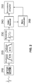
- the FIG. 2 shows the block diagram of an inventively extended heart stimulator.
- the IEGM signals are first amplified and digitized (210) and then conditioned in a digital filter unit (220) for subsequent signal processing.
- an adaptive comparator stage (230) the sense events are generated and then supplied to the noise and refractory members (240).
- the signals thus evaluated are fed to the stimulation timer (250) and the pacemaker stimulation is controlled with this information.
- the block diagram comprises an additional mode switch (260) which is controlled via a connection from the noise evaluation (240) and, whenever noise events have occurred, the stimulation timer (250) for a programmed duration in an asynchronous stimulation mode ( V00, D00) switches.
- the FIG. 3 shows an exemplary timing diagram, that is the FIG. 3 shows the control of the in FIG. 2 shown mode switch. Shown are the intracardiac IEGM channel (310) and the marker channel (320). In this example, a fault (330) sets in after a sensed R-wave (S). In the marker channel, the disturbance (330) can be identified by the noise markers (N). Exceeds the duration of an uninterrupted Noise state an adjustable time (340), then the mode switch (260) signals the pacing timer (250) to switch to asynchronous pacing (350). By introducing the required noise duration (340), a distinction can be made between multiple triggering of an R-wave (also rated as noise for a short time) and a relevant pulsed disturbance, which necessitates a mode changeover.
- an R-wave also rated as noise for a short time
- a relevant pulsed disturbance which necessitates a mode changeover.
- FIG. 4 shows that in FIG. 1 illustrated example, but now with the Störumscilles invention.
- ventricular pacing is initially inhibited by the onset of MRI (410).
- the implant now automatically switches to a programmed fault mode for six cycles, here a V00 stimulation (420). Thereafter, the switch automatically returns to the original DDD mode. Since the disorder is still present, further stimulation is inhibited (430) and then switched back to V00 mode for six cycles.
- the number of cycles and / or the duration of the asynchronous stimulation can be varied accordingly.
- implants and methods according to the invention are independent of the selected detection and detection methods for the pulsed sources of interference.
- implants on the one hand, as accurate detection methods as possible and, on the other hand, the lowest possible energy requirement are preferred.
- This results in advantageous detectors and / or detection possibilities the use of GMR sensors, MagFET sensors, Hall sensors, electro-optical converters, the monitoring of battery voltages during capacitor charging processes, the detection of RF fields, the detection of magnetic gradient fields, and the detection of Electromagnetic fields induced currents.
- the technology will be implemented in conjunction with other technologies such as, but not limited to, MRI (Magnetic Resonance Imaging) and MRI safe operation, to leverage synergies.
- the methods and / or detection devices can be used for different applications.
Landscapes
- Health & Medical Sciences (AREA)
- Cardiology (AREA)
- Heart & Thoracic Surgery (AREA)
- Engineering & Computer Science (AREA)
- Biomedical Technology (AREA)
- Nuclear Medicine, Radiotherapy & Molecular Imaging (AREA)
- Radiology & Medical Imaging (AREA)
- Life Sciences & Earth Sciences (AREA)
- Animal Behavior & Ethology (AREA)
- General Health & Medical Sciences (AREA)
- Public Health (AREA)
- Veterinary Medicine (AREA)
- Electrotherapy Devices (AREA)
Abstract
Description
- Die Erfindung bezieht sich auf eine Vorrichtung und ein Verfahren zum Umgang mit elektromagnetischen Feldern, speziell solche Felder, wie sie bei Kauteranwendungen auftreten.
- Obwohl Kauteranwendungen einen immer höheren Stellenwert in der Medizin, besonders bei der chirurgischen Intervention und im Zusammenhang mit Gefäßverletzungen, erhalten, ist ein Teil der Patienten für Kauteranwendungen kontraindiziert. Eine solche Kontraindikation kann durch ein mindestens teilweise implantiertes medizinisches Gerät (im Folgenden auch Implantat oder IMD) gegeben sein, insbesondere bei sogenannten ICD-(Implanted Cardiverter Defribrilator) Patienten.
- Bei Kauteranwendungen im Stand der Technik handelt es sich zumeist um elektrisches Kautern, das heißt, dass Kautern mit Hilfe eines durch Stromfluss erhitzten Objektes, zum Beispiel eines dünnen Drahtes, durchgeführt wird. Das Kautern wird auch als Diathermie bezeichnet. Man unterscheidet neben der elektrischen hochfrequenten Diathermie auch noch die Ultraschalldiathermie und die Mikrowellendiathermie. Als im Allgemeinen unkritisch für IMD-Träger gilt die Ultraschalldiathermie, während die Hochfrequenzdiathermie und die Mikrowellendiathermie mit einem IMD interferieren können.
- Um Kauteranwendungen, speziell mittels der Hochfrequenzdiathermie und der Mikrowellendiathermie dennoch zu ermöglichen, sind vor allem asynchrone Betriebsarten für Schrittmacher und ICD Patienten bekannt. Diese haben den Nachteil, dass von der asynchronen Stimulation ein erhebliches proarrhythmisches Risiko ausgeht. Insbesondere bei ICD-Patienten ist eine unnötige asynchrone Stimulation kontraindiziert.
- Derzeit bekannte Störerkennungen aller etablierten Schrittmacher (IPG)- und ICD-Systeme sind hierfür nicht anwendbar, da diese sofort nach Ende des Anliegens der Störung den asynchronen Störmode verlassen. Damit versagt diese bei gepulsten Störungen, wie sie bei unter anderem Kauteranwendungen auftreten.
- Aufgabe der Erfindung ist es, eine Vorrichtung und eine Methode für medizinische Geräte und implantierbare medizinische Geräte bereitzustellen, die die Nachteile des Stands der Technik beheben und einen sicheren Betrieb in Gegenwart von elektromagnetischen Störfeldern, speziell ausgehend von Kauteranwendungen, erlauben.
- Die Aufgabe wird durch ein zumindest teilweise implantierbares medizinisches Gerät (IMD) mit den Merkmalen des Anspruchs 1 und dem Verfahren nach Anspruch 12 gelöst.
- Dabei beinhaltete das zumindest teilweise implantierbare medizinische Gerät (IMD) mindestens: eine Einheit zur Detektion von elektromagnetischen Störfeldern, wobei die Einheit über mindestens einen Sensor und/oder Indikator für elektromagnetische Störfelder verfügt und/oder ausgelegt ist, nicht physiologische Signale zu detektieren und zu erkennen, mindestens eine Steuereinheit, die mit der Einheit zur Detektion von elektromagnetischen Störfeldern verbindbar ist, mindestens beinhaltend einen Zeitmesser und eine Detektionseinheit für elektrische Messgrößen und/oder mindestens beinhaltend eine Stimulationseinheit, mindestens eine Elektrodenleitung, die mit der Steuereinheit und/oder mit der Einheit zur Detektion von elektromagnetischen Störfeldern verbindbar ist und die am anderen Ende eine Elektrode aufweist, die im zumindest teilweise implantierten Zustand im Kontakt mit Körpergewebe bringbar ist und die sich entweder im Körperinneren erstreckt oder auf der Oberfläche eines Implantates befinden kann, wobei die Einheit zur Detektion von elektromagnetischen Störfeldern bei der Erkennung von nicht physiologischen Signalen und/oder elektromagnetischen Störfeldern für eine erste vorgebbare Zeit die detektierten Signale als nicht physiologische Signale bewertet und/oder die Stimulationseinheit für eine zweite vorgegebene Zeit in einem asynchronen Betriebszustand versetzt wird, in dem der Träger des IMD asynchron stimuliert wird.
- Bevorzugt ist, dass das IMD ein implantierbarer oder externer Stimulator ist.
- Dabei ist unter einem externen Stimulator zum Beispiel, aber nicht beschränkt auf, ein externer Herzstimulator, ein externer Defibrillator und/oder Neurostimulator zu verstehen, wobei bei externen Stimulatoren Teile implantiert oder temporär implantiert sein können.
- Ebenfalls bevorzugt ist, dass das IMD ein Implantat zur Überwachung von Körperfunktionen ist, wie, aber nicht beschränkt auf, einen implantierbaren Herzmonitor. Ein solches Implantat kann über sich in das Körperinnere erstreckende Elektrodenleitungen mit mindestens einer Elektrode und/oder über mindestens eine Elektrode auf der Implantatsoberfläche zur Detektion von physiologischen Signalen verfügen.
- Auch wird bevorzugt, dass der asynchrone Betriebszustand immer dann für die zweite vorgegebene Zeit aktiviert wird, wenn mindestens ein Stimulationsimpuls abgegeben wurde bei gleichzeitiger Erkennung von nicht physiologischen Signalen und/oder bei Erkennung von elektromagnetischen Störfeldern.
- Des Weiteren wird bevorzugt, dass der asynchrone Betriebszustand immer dann für die zweite vorgegebene Zeit aktiviert wird, wenn eine vorbestimmbare Mindestanzahl von nicht physiologischen Signalen in einem vorbestimmbaren Zeitfenster detektiert wird.
- Bevorzugt ist auch, dass der asynchrone Betriebszustand ein A00, V00 oder D00 Betriebszustand ist.
- Ebenfalls bevorzugt wird, dass der asynchrone Betriebszustand eine biventrikuläre Stimulation einschließt.
- Auch wird bevorzugt, dass der asynchrone Betriebszustand mit einer Änderung der Stimulationsfrequenz verbunden ist, wobei sich die asynchrone Stimulationsfrequenz aus der Herzfrequenz vor einer detektierten elektromagnetischen Störung und/oder der Detektion von nicht physiologischen Signalen berechnet.
Eine mögliche Berechnungsform der asynchronen Stimulationsfrequenz aus der Herzfrequenz vor einer detektierten elektromagnetischen Störung und/oder der Detektion von nicht physiologischen Signalen besteht in dem Hinzuaddieren von einer vorherbestimmbaren Anzahl von Herzschlägen pro Zeiteinheit, wie aber nicht beschränkt auf Herzfrequenz + 10 bpm. - Des Weiteren wird bevorzugt, dass der asynchrone Betriebszustand mit einer Änderung der Stimulationsamplitude und/oder der Stimulationspulsbreite verbunden ist.
- Bevorzugt ist auch, dass detektierte Signale als nicht physiologische Signale bewertet werden und/oder der asynchrone Betriebszustand nur für eine vorgebbare erste Zeit durch die Erkennung von nicht physiologischen Signalen und/oder elektromagnetischen Störfeldern aktivierbar ist.
- Besonders bevorzugt wird, dass die vorgebbare erste Zeit im Bereich von Stunden und/oder Tagen liegt.
- Ebenfalls bevorzug wird, dass die Einheit zur Detektion von elektromagnetischen Störfeldern mindestens einen der folgenden Sensoren oder Indikatoren umfasst: GMR-Sensor, MagFET-Sensor, Hallsensor, elektrooptische Wandler als Indikator, die Überwachung von Batteriespannungen während Kondensatorladeprozessen als Indikator, die Detektion von RF-Feldern als Indikator, die Detektion von magnetischen Grandientenfeldern als Indikator, und die Detektion von durch elektromagnetische Felder induzierten Strömen als Indikator.
- Gelöst wird die Aufgabe auch durch ein Verfahren zum Umgang mit von einem IMD detektierbaren elektromagnetischen Störfeldern, wobei bei der Erkennung von nicht physiologische Signalen und/oder elektromagnetischen Störfeldern für eine vorgegebene erste Zeit die detektierten Signale als nicht physiologische Signale bewertet und/oder eine Stimulationseinheit für eine zweite vorgegebene Zeit in einem asynchronen Betriebszustand versetzt wird, in dem der Träger des IMD asynchron stimuliert wird. Das Verfahren lässt sich beispielsweise mit jedem der obigen IMDs ausführen.
- Einige Aspekte der Erfindung werden in den
Figuren 1 bis 4 dargestellt. - Fig. 1
- Schematische Darstellung der Ausgangssituation bei gepulsten Störungen
- Fig. 2
- Blockschaltbild einer erfindungsgemäßen Herzstimulators.
- Fig. 3
- Schematische Darstellung der Steuerung des in
Figur 2 dargestellten Modeumschalters. - Fig. 4
- Beispielhafte Situation mit erfindungsgemäßer Lösung.
- In einem Beispiel wird das erfindungsgemäße System in einem Schrittmacher implementiert. Schrittmacherabhängige Patienten werden im Falle einer gepulsten Störung möglicherweise dauerhaft nicht stimuliert, da die herkömmliche Noiseerkennung bei ICD/IPG den Störmode sofort verlässt, wenn die Störung beendet wird. Um die Stimulation während einer Kauteranwendung jedoch zu gewährleisten, wird hier ein erweiterter Störmode implementiert, der einen zusätzlichen Timer umfasst, um so die Zeit einer asynchronen Stimulation nach einer einmaligen Störerkennung zu verlängern. Diese Zeit wird dabei an die typische Dauer der Prozedur per vorheriger Programmierung angepasst. Dieser Störmode kann zeitlich limitiert werden, wie, aber nicht beschränkt, auf Stunden, Tage oder Wochen.
- In einem anderen Beispiel wird der erweiterte Störmode in einem Herzmonitor implementiert, der während einer gepulsten Störung möglicherweise dauerhaft keine Herzsignale aufzeichnet und/oder die identifizierten Störungen markiert, um eine Fehlinterpretation der aufgezeichneten Daten zu verhindern. Der Störmode wird erst dann wieder verlassen, wenn nach einer voreinstellbaren Zeit keine weiteren Störungen detektiert wurden.
-
Figur 1 stellt eine mit dem Stand der Technik typische Situation dar. Hier wird die Stimulation eines Schrittmachers durch die gepulsten Störfelder des MRT fälschlicherweise inhibiert und damit eine Unterversorgung des Patienten herbeigeführt (100). - Dargestellt ist hier das Oberflächen-EKG (110) und das (optisch übertragene) intrakardiale rechtsventrikuläre Elektrogramm (120) eines Zweikammerschrittmachers bei einem Patienten mit totalem AV-Block.
Vor dem Einsetzen der MRT-Störung wird der Patient vorhofsynchron stimuliert (130). Diese Stimulationsimpulse werden jedoch durch die gepulste Störung (140) regelmäßig inhibiert. Diese wiederholte Inhibierung tritt auf, da die Störung immer wieder unterbrochen wird und der Schrittmacher daher nicht in einen Störmode schalten kann.
In diesem Beispiel hat der Patient noch einen sehr langsamen ventrikulären Ersatzrhythmus (150), so dass eine minimale Pumpfunktion des Ventrikels gegeben war. Ohne diesen Ersatzrhythmus wäre hier ein Herzstillstand eingetreten. Neben dieser Möglichkeit kann der Stimulator aber auch im Vorfeld von zum Beispiel einer Kauteranwendung in einen asynchronen Stimulationsmodus versetzt werden, was aber ein erhöhtes Risiko von Tachykardien birgt. - Die
Figur 2 zeigt das Blockschaltbild eines erfindungsgemäß erweiterten Herzstimulators. Die IEGM-Signale werden zunächst verstärkt und digitalisiert (210) und anschließend in einer digitalen Filtereinheit (220) für die nachfolgende Signalverarbeitung konditioniert. In einer adaptiven Komparatorstufe (230) werden die Senseereignisse generiert und anschließend den Noise- und Refraktärgliedern (240) zugeführt. Die so bewerteten Signale werden dem Stimulationszeitgeber (250) zugeführt und mit dieser Information die Schrittmacherstimulation gesteuert.
Erfindungsgemäß umfasst das Blockschaltbild einen zusätzlichen Modeumschalter (260), der über eine Verbindung von der Noise-Bewertung (240) gesteuert wird und immer dann, wenn Noise-Ereignisse aufgetreten sind, den Stimulationszeitgeber (250) für eine programmierte Dauer in einen asynchronen Stimulationsmode (V00, D00) umschaltet. - Die
Figur 3 zeigt ein beispielhaftes Timing-Diagramm, das heißt dieFigur 3 zeigt die Steuerung des inFigur 2 gezeigten Modeumschalters. Dargestellt sind der intrakardiale IEGM-Kanal (310) und der Markerkanal (320). In diesem Beispiel setzt eine Störung (330) nach einer wahrgenommenen R-Welle (S) ein. Im Markerkanal ist die Störung (330) anhand der Noise-Marker (N) erkennbar. Überschreitet die Dauer eines ununterbrochenen Noise-Zustandes eine einstellbare Zeit (340), dann signalisiert der Modeumschalter (260) dem Stimulationszeitgeber (250) eine Umschaltung in eine asynchrone Stimulation (350). Durch die Einführung der geforderten Noise-Dauer (340) kann zwischen Mehrfachtriggerung einer R-Welle (wird auch kurzzeitig als Noise bewertet) und einer relevanten gepulsten Störung unterschieden, die eine Modeumschaltung erforderlich macht. - Die
Figur 4 zeigt das inFigur 1 dargestellte Beispiel, nun jedoch mit der erfindungsgemäßen Störumschaltung. Auch hier wird die ventrikuläre Stimulation zunächst durch die einsetzende MRT-Störung inhibiert (410). Allerdings schaltet nun das Implantat automatisch für sechs Zyklen in einen programmierten Störmode, hier eine V00-Stimulation (420). Danach erfolgt automatisch die Umschaltung zurück in die ursprüngliche DDD-Betriebsart. Da die Störung noch vorhanden ist, wird eine weitere Stimulation inhibiert (430) und darauf hin wieder für sechs Zyklen in den V00-Mode geschaltet.
So ist es möglich, eine zuverlässige Back-up-Stimulation bei gepulsten Störungen zu realisieren, die den Patienten nicht für einen langen Zeitraum einer asynchronen Stimulation aussetzt.
Die Anzahl der Zyklen und/oder die Dauer der asynchronen Stimulation kann entsprechend variiert werden. - Erfindungsgemäße Implantate und Verfahren sind prinzipiell unabhängig von den gewählten Detektions- und Erkennungsmethoden für die gepulsten Störquellen. Allerdings werden für Implantate einerseits möglichst genaue Detektionsmethoden und andererseits ein möglichst geringer Energiebedarf bevorzugt. Damit ergeben sich als vorteilhafte Detektoren und/oder Erkennungsmöglichkeiten der Einsatz von GMR-Sensoren, MagFET-Sensoren, Hallsensoren, elektrooptische Wandlern, die Überwachung von Batteriespannungen während Kondensatorladeprozessen, die Detektion von RF-Feldern, die Detektion von magnetischen Grandientenfeldern, und die Detektion von durch elektromagnetische Felder induzierten Strömen. Bevorzugt wird die Technologie in Zusammenhang mit anderen Technologien, wie, aber nicht beschränkt auf, MRT-Erkennung (MRT = Magnetresonanztomographie) und MRT-sicherer Betrieb, implementiert um Synergieeffekte nutzen zu können. So können die Methoden und/oder Detektionsvorrichtungen für verschiedene Anwendungen genutzt werden.
- Es wird somit ermöglicht, eine zuverlässige Stimulation auch bei gepulsten elektromagnetischen Störungen sicherzustellen, so dass Kauter-Anwendungen für Schrittmacher und ICD-Systeme eingesetzt werden können, ohne dass zuvor eine asynchrone Stimulationsbetriebsart programmiert werden muss. Auch sind andere Anwendungen mit gepulsten elektromagnetischen Störungen möglich, wie sie zum Beispiel bei dem Einsatz von elektromagnetischen Radiofrequenzfeldern und/oder Gradientenfeldern auftreten.
Claims (12)
- Zumindest teilweise implantierbares medizinisches Gerät (IMD), mit- einer Einheit zur Detektion von elektromagnetischen Störfeldern, wobei die Einheit über mindestens einen Sensor und/oder Indikator für elektromagnetische Störfelder verfügt und/oder ausgelegt ist, nicht physiologische Signale zu detektieren und zu erkennen,- mindestens einer Steuereinheit, die mit der Einheit zur Detektion von elektromagnetischen Störfeldern verbindbar ist, mindestens beinhaltend einen Zeitmesser und eine Detektionseinheit für elektrische Messgrößen und/oder mindestens beinhaltend eine Stimulationseinheit,- mindestens einer Elektrodenleitung, die mit der Steuereinheit und/oder mit der Einheit zur Detektion von elektromagnetischen Störfeldern verbindbar ist und die am anderen Ende eine Elektrode aufweist, die im zumindest teilweise implantierten Zustand im Kontakt mit Körpergewebe bringbar ist und die sich entweder im Körperinneren erstreckt oder auf der Oberfläche eines Implantates befinden kann,
gekennzeichnet dadurch, dass
die Einheit zur Detektion von elektromagnetischen Störfeldern bei der Erkennung von nicht physiologischen Signalen und/oder elektromagnetischen Störfeldern für eine erste vorgebbare Zeit die detektierten Signale als nicht physiologische Signale bewertet und/oder die Stimulationseinheit für eine zweite vorgegebene Zeit in einem asynchronen Betriebszustand versetzt wird, in dem der Träger des IMD asynchron stimuliert wird. - IMD nach Anspruch 1, dadurch gekennzeichnet, dass das IMD ein implantierbarer oder externer Stimulator ist.
- IMD nach Anspruch 1 oder 2, dadurch gekennzeichnet, dass der asynchrone Betriebszustand immer dann für die zweite vorgegebene Zeit aktiviert wird, wenn mindestens ein Stimulationsimpuls abgegeben wurde bei gleichzeitiger Erkennung von nicht physiologischen Signalen und/oder bei Erkennung von elektromagnetischen Störfeldern.
- IMD nach einem der vorangegangenen Ansprüche, dadurch gekennzeichnet, dass der asynchrone Betriebszustand immer dann für die zweite vorgegebene Zeit aktiviert wird, wenn eine vorbestimmbare Mindestanzahl von nicht physiologischen Signalen in einem vorbestimmbaren Zeitfenster detektiert wird.
- IMD nach einem der vorangegangenen Ansprüche, dadurch gekennzeichnet, dass der asynchrone Betriebszustand ein A00, V00 oder D00 Betriebszustand ist.
- IMD nach einem der vorangegangenen Ansprüche, dadurch gekennzeichnet, dass der asynchrone Betriebszustand eine biventrikuläre Stimulation einschließt.
- IMD nach einem der vorangegangenen Ansprüche, dadurch gekennzeichnet, dass der asynchrone Betriebszustand mit einer Änderung der Stimulationsfrequenz verbunden ist, wobei sich die asynchrone Stimulationsfrequenz aus der Herzfrequenz vor einer detektierten elektromagnetischen Störung und/oder der Detektion von nicht physiologischen Signalen berechtet.
- IMD nach einem der vorangegangenen Ansprüche, dadurch gekennzeichnet, dass der asynchrone Betriebszustand mit einer Änderung der Stimulationsamplitude und/oder der Stimulationspulsbreite verbunden ist.
- IMD nach einem der vorangegangenen Ansprüche, dadurch gekennzeichnet, dass detektierte Signale als nicht physiologische Signale bewertet werden und/oder der asynchrone Betriebszustand nur für einen vorgebbare ersten Zeit durch die Erkennung von nicht physiologische Signalen und/oder elektromagnetischen Störfeldern aktivierbar ist.
- IMD nach Anspruch 9, dadurch gekennzeichnet, dass die vorgebbare erste Zeit im Bereich von Stunden und/oder Tagen liegt.
- IMD nach einem der vorangegangenen Ansprüche, dadurch gekennzeichnet, dass die Einheit zur Detektion von elektromagnetischen Störfeldern mindestens einen der folgenden Sensoren oder Indikatoren umfasst:- GMR-Sensor,- MagFET-Sensor,- Hallsensor,- elektrooptische Wandler als Indikator,- die Überwachung von Batteriespannungen während Kondensatorladeprozessen als Indikator,- die Detektion von RF-Feldern als Indikator,- die Detektion von magnetischen Grandientenfeldern als Indikator, und- die Detektion von durch elektromagnetische Felder induzierten Strömen als Indikator.
- Verfahren zum Umgang mit von einem IMD detektierbaren elektromagnetischen Störfeldern, dadurch gekennzeichnet, dass bei der Erkennung von nicht physiologische Signalen und/oder elektromagnetischen Störfeldern für eine vorgegebene erste Zeit die detektierten Signale als nicht physiologische Signale bewertet und/oder eine Stimulationseinheit für eine zweite vorgegebene Zeit in einem asynchronen Betriebszustand versetzt wird, in dem der Träger des IMD asynchron stimuliert wird.
Applications Claiming Priority (1)
| Application Number | Priority Date | Filing Date | Title |
|---|---|---|---|
| US28886209P | 2009-12-22 | 2009-12-22 |
Publications (2)
| Publication Number | Publication Date |
|---|---|
| EP2338561A1 true EP2338561A1 (de) | 2011-06-29 |
| EP2338561B1 EP2338561B1 (de) | 2020-03-25 |
Family
ID=43799508
Family Applications (1)
| Application Number | Title | Priority Date | Filing Date |
|---|---|---|---|
| EP10192883.6A Active EP2338561B1 (de) | 2009-12-22 | 2010-11-29 | Implantierbares medizinisches Gerät mit verlängertem Noise-Mode |
Country Status (2)
| Country | Link |
|---|---|
| US (1) | US8649877B2 (de) |
| EP (1) | EP2338561B1 (de) |
Families Citing this family (1)
| Publication number | Priority date | Publication date | Assignee | Title |
|---|---|---|---|---|
| WO2024104706A1 (en) | 2022-11-18 | 2024-05-23 | Biotronik Se & Co. Kg | Implantable medical device having an automatic surgery recognition mode |
Citations (4)
| Publication number | Priority date | Publication date | Assignee | Title |
|---|---|---|---|---|
| US20060167496A1 (en) * | 2005-01-26 | 2006-07-27 | Nelson Shannon D | System and method for operating an implantable medical device in a disruptive energy field |
| US20060293591A1 (en) * | 2005-05-12 | 2006-12-28 | Wahlstrand John D | Implantable medical device with MRI and gradient field induced capture detection methods |
| US20070203523A1 (en) * | 2006-02-28 | 2007-08-30 | Betzold Robert A | Implantable medical device with adaptive operation |
| US7561915B1 (en) * | 2004-12-17 | 2009-07-14 | Cardiac Pacemakers, Inc. | MRI system having implantable device safety features |
Family Cites Families (3)
| Publication number | Priority date | Publication date | Assignee | Title |
|---|---|---|---|---|
| US5697958A (en) * | 1995-06-07 | 1997-12-16 | Intermedics, Inc. | Electromagnetic noise detector for implantable medical devices |
| US6287304B1 (en) * | 1999-10-15 | 2001-09-11 | Neothermia Corporation | Interstitial cauterization of tissue volumes with electrosurgically deployed electrodes |
| US7693568B2 (en) * | 2006-03-30 | 2010-04-06 | Medtronic, Inc. | Medical device sensing and detection during MRI |
-
2010
- 2010-11-29 EP EP10192883.6A patent/EP2338561B1/de active Active
- 2010-12-18 US US12/972,463 patent/US8649877B2/en not_active Expired - Fee Related
Patent Citations (4)
| Publication number | Priority date | Publication date | Assignee | Title |
|---|---|---|---|---|
| US7561915B1 (en) * | 2004-12-17 | 2009-07-14 | Cardiac Pacemakers, Inc. | MRI system having implantable device safety features |
| US20060167496A1 (en) * | 2005-01-26 | 2006-07-27 | Nelson Shannon D | System and method for operating an implantable medical device in a disruptive energy field |
| US20060293591A1 (en) * | 2005-05-12 | 2006-12-28 | Wahlstrand John D | Implantable medical device with MRI and gradient field induced capture detection methods |
| US20070203523A1 (en) * | 2006-02-28 | 2007-08-30 | Betzold Robert A | Implantable medical device with adaptive operation |
Also Published As
| Publication number | Publication date |
|---|---|
| US8649877B2 (en) | 2014-02-11 |
| US20110152973A1 (en) | 2011-06-23 |
| EP2338561B1 (de) | 2020-03-25 |
Similar Documents
| Publication | Publication Date | Title |
|---|---|---|
| DE602004007789T2 (de) | Vorrichtung zur verwendung eines beschleunigungsmessersignals zur verbesserung der detektion von ventrikulärer arrhythmie | |
| EP2060299B1 (de) | Biventrikulärer Herzstimulator | |
| DE69123558T2 (de) | Implantierbarer, auf hämodynamische Grössen ansprechender Herzschrittmacher zur Herzrhythmuskorrektur bzw. Defibrillation | |
| JP5740047B2 (ja) | 植込み型医療システム | |
| EP2401031B1 (de) | Übersprechsignaldetektor in implantierbaren geräten | |
| EP2338559B1 (de) | MRI-Gradientenfelddetektor | |
| EP2543411A1 (de) | Medizinisches Implantat und Verfahren zur sicheren Implantatkommunikation | |
| EP2353644A1 (de) | Kardioverter/Defibrillator und Signalverarbeitungsvorrichtung zur Klassifikation intrakardialer Signale | |
| EP2952224A1 (de) | Detektor für elektromagnetische felder | |
| EP3025759A1 (de) | Mrt-taugliches aktives implantierbares gerät | |
| EP2135640A1 (de) | Elektrotherapieeinrichtung zur Behandlung tachykarder Rhythmusstörungen eines Herzens | |
| EP3025757B1 (de) | Mrt-taugliches aktives implantierbares gerät | |
| DE602007000008T2 (de) | Aktives medizinisches Implantat zur Herzstimulation, Resynchronisation, Kardioversion und/oder Defibrillation, das Mittel zum Erfassen eines Sondenbruchs umfasst | |
| EP2676697B1 (de) | Dislokationssensor | |
| EP3542716A1 (de) | Medizinisches gerät und methode zur auswertung von daten hinsichtlich fehler in einer elektrodenleitung | |
| EP2338566B1 (de) | Implantierbares medizinisches Gerät mit Mitteln zur Rekonstruktion eines unvollständig erfassten Signals | |
| EP2338560B1 (de) | Implantierbarer Kardioverter-Defibrillator (ICD) mit MRT-Störerkennungseinheit | |
| EP2140910B1 (de) | Herzstimulator zur Behandlung tachykarder Rhythmusstörungen eines Herzens | |
| EP2338561B1 (de) | Implantierbares medizinisches Gerät mit verlängertem Noise-Mode | |
| EP2422843B1 (de) | Implantierbares elektronisches Therapiegerät | |
| EP2111893A1 (de) | Ventrikulärer Herzstimulator | |
| EP2135641A1 (de) | Antitachykarder Herzstimulator | |
| EP2826524B1 (de) | Herztherapiegerät zum Erfassen ventrikulärer Tachykardien und Fibrillationen | |
| EP3679984A1 (de) | Implantierbare anordnung zur stimulation eines menschlichen oder tierischen herzens | |
| EP2174688B1 (de) | Vorrichtung zur Verarbeitung von Herzsignalen |
Legal Events
| Date | Code | Title | Description |
|---|---|---|---|
| PUAI | Public reference made under article 153(3) epc to a published international application that has entered the european phase |
Free format text: ORIGINAL CODE: 0009012 |
|
| AK | Designated contracting states |
Kind code of ref document: A1 Designated state(s): AL AT BE BG CH CY CZ DE DK EE ES FI FR GB GR HR HU IE IS IT LI LT LU LV MC MK MT NL NO PL PT RO RS SE SI SK SM TR |
|
| AX | Request for extension of the european patent |
Extension state: BA ME |
|
| 17P | Request for examination filed |
Effective date: 20111214 |
|
| STAA | Information on the status of an ep patent application or granted ep patent |
Free format text: STATUS: EXAMINATION IS IN PROGRESS |
|
| 17Q | First examination report despatched |
Effective date: 20170515 |
|
| RAP1 | Party data changed (applicant data changed or rights of an application transferred) |
Owner name: BIOTRONIK SE & CO. KG |
|
| GRAP | Despatch of communication of intention to grant a patent |
Free format text: ORIGINAL CODE: EPIDOSNIGR1 |
|
| STAA | Information on the status of an ep patent application or granted ep patent |
Free format text: STATUS: GRANT OF PATENT IS INTENDED |
|
| INTG | Intention to grant announced |
Effective date: 20191106 |
|
| RIN1 | Information on inventor provided before grant (corrected) |
Inventor name: WEISS, INGO Inventor name: DOERR, THOMAS |
|
| GRAS | Grant fee paid |
Free format text: ORIGINAL CODE: EPIDOSNIGR3 |
|
| GRAA | (expected) grant |
Free format text: ORIGINAL CODE: 0009210 |
|
| STAA | Information on the status of an ep patent application or granted ep patent |
Free format text: STATUS: THE PATENT HAS BEEN GRANTED |
|
| AK | Designated contracting states |
Kind code of ref document: B1 Designated state(s): AL AT BE BG CH CY CZ DE DK EE ES FI FR GB GR HR HU IE IS IT LI LT LU LV MC MK MT NL NO PL PT RO RS SE SI SK SM TR |
|
| REG | Reference to a national code |
Ref country code: GB Ref legal event code: FG4D Free format text: NOT ENGLISH |
|
| REG | Reference to a national code |
Ref country code: AT Ref legal event code: REF Ref document number: 1247869 Country of ref document: AT Kind code of ref document: T Effective date: 20200415 Ref country code: IE Ref legal event code: FG4D Free format text: LANGUAGE OF EP DOCUMENT: GERMAN |
|
| REG | Reference to a national code |
Ref country code: DE Ref legal event code: R096 Ref document number: 502010016547 Country of ref document: DE |
|
| PG25 | Lapsed in a contracting state [announced via postgrant information from national office to epo] |
Ref country code: NO Free format text: LAPSE BECAUSE OF FAILURE TO SUBMIT A TRANSLATION OF THE DESCRIPTION OR TO PAY THE FEE WITHIN THE PRESCRIBED TIME-LIMIT Effective date: 20200625 Ref country code: RS Free format text: LAPSE BECAUSE OF FAILURE TO SUBMIT A TRANSLATION OF THE DESCRIPTION OR TO PAY THE FEE WITHIN THE PRESCRIBED TIME-LIMIT Effective date: 20200325 Ref country code: FI Free format text: LAPSE BECAUSE OF FAILURE TO SUBMIT A TRANSLATION OF THE DESCRIPTION OR TO PAY THE FEE WITHIN THE PRESCRIBED TIME-LIMIT Effective date: 20200325 |
|
| PG25 | Lapsed in a contracting state [announced via postgrant information from national office to epo] |
Ref country code: HR Free format text: LAPSE BECAUSE OF FAILURE TO SUBMIT A TRANSLATION OF THE DESCRIPTION OR TO PAY THE FEE WITHIN THE PRESCRIBED TIME-LIMIT Effective date: 20200325 Ref country code: GR Free format text: LAPSE BECAUSE OF FAILURE TO SUBMIT A TRANSLATION OF THE DESCRIPTION OR TO PAY THE FEE WITHIN THE PRESCRIBED TIME-LIMIT Effective date: 20200626 Ref country code: SE Free format text: LAPSE BECAUSE OF FAILURE TO SUBMIT A TRANSLATION OF THE DESCRIPTION OR TO PAY THE FEE WITHIN THE PRESCRIBED TIME-LIMIT Effective date: 20200325 Ref country code: LV Free format text: LAPSE BECAUSE OF FAILURE TO SUBMIT A TRANSLATION OF THE DESCRIPTION OR TO PAY THE FEE WITHIN THE PRESCRIBED TIME-LIMIT Effective date: 20200325 Ref country code: BG Free format text: LAPSE BECAUSE OF FAILURE TO SUBMIT A TRANSLATION OF THE DESCRIPTION OR TO PAY THE FEE WITHIN THE PRESCRIBED TIME-LIMIT Effective date: 20200625 |
|
| REG | Reference to a national code |
Ref country code: NL Ref legal event code: MP Effective date: 20200325 |
|
| REG | Reference to a national code |
Ref country code: LT Ref legal event code: MG4D |
|
| PG25 | Lapsed in a contracting state [announced via postgrant information from national office to epo] |
Ref country code: NL Free format text: LAPSE BECAUSE OF FAILURE TO SUBMIT A TRANSLATION OF THE DESCRIPTION OR TO PAY THE FEE WITHIN THE PRESCRIBED TIME-LIMIT Effective date: 20200325 |
|
| PG25 | Lapsed in a contracting state [announced via postgrant information from national office to epo] |
Ref country code: PT Free format text: LAPSE BECAUSE OF FAILURE TO SUBMIT A TRANSLATION OF THE DESCRIPTION OR TO PAY THE FEE WITHIN THE PRESCRIBED TIME-LIMIT Effective date: 20200818 Ref country code: EE Free format text: LAPSE BECAUSE OF FAILURE TO SUBMIT A TRANSLATION OF THE DESCRIPTION OR TO PAY THE FEE WITHIN THE PRESCRIBED TIME-LIMIT Effective date: 20200325 Ref country code: LT Free format text: LAPSE BECAUSE OF FAILURE TO SUBMIT A TRANSLATION OF THE DESCRIPTION OR TO PAY THE FEE WITHIN THE PRESCRIBED TIME-LIMIT Effective date: 20200325 Ref country code: CZ Free format text: LAPSE BECAUSE OF FAILURE TO SUBMIT A TRANSLATION OF THE DESCRIPTION OR TO PAY THE FEE WITHIN THE PRESCRIBED TIME-LIMIT Effective date: 20200325 Ref country code: SK Free format text: LAPSE BECAUSE OF FAILURE TO SUBMIT A TRANSLATION OF THE DESCRIPTION OR TO PAY THE FEE WITHIN THE PRESCRIBED TIME-LIMIT Effective date: 20200325 Ref country code: RO Free format text: LAPSE BECAUSE OF FAILURE TO SUBMIT A TRANSLATION OF THE DESCRIPTION OR TO PAY THE FEE WITHIN THE PRESCRIBED TIME-LIMIT Effective date: 20200325 Ref country code: SM Free format text: LAPSE BECAUSE OF FAILURE TO SUBMIT A TRANSLATION OF THE DESCRIPTION OR TO PAY THE FEE WITHIN THE PRESCRIBED TIME-LIMIT Effective date: 20200325 Ref country code: IS Free format text: LAPSE BECAUSE OF FAILURE TO SUBMIT A TRANSLATION OF THE DESCRIPTION OR TO PAY THE FEE WITHIN THE PRESCRIBED TIME-LIMIT Effective date: 20200725 |
|
| REG | Reference to a national code |
Ref country code: DE Ref legal event code: R097 Ref document number: 502010016547 Country of ref document: DE |
|
| PG25 | Lapsed in a contracting state [announced via postgrant information from national office to epo] |
Ref country code: IT Free format text: LAPSE BECAUSE OF FAILURE TO SUBMIT A TRANSLATION OF THE DESCRIPTION OR TO PAY THE FEE WITHIN THE PRESCRIBED TIME-LIMIT Effective date: 20200325 Ref country code: ES Free format text: LAPSE BECAUSE OF FAILURE TO SUBMIT A TRANSLATION OF THE DESCRIPTION OR TO PAY THE FEE WITHIN THE PRESCRIBED TIME-LIMIT Effective date: 20200325 Ref country code: DK Free format text: LAPSE BECAUSE OF FAILURE TO SUBMIT A TRANSLATION OF THE DESCRIPTION OR TO PAY THE FEE WITHIN THE PRESCRIBED TIME-LIMIT Effective date: 20200325 |
|
| PLBE | No opposition filed within time limit |
Free format text: ORIGINAL CODE: 0009261 |
|
| STAA | Information on the status of an ep patent application or granted ep patent |
Free format text: STATUS: NO OPPOSITION FILED WITHIN TIME LIMIT |
|
| PG25 | Lapsed in a contracting state [announced via postgrant information from national office to epo] |
Ref country code: PL Free format text: LAPSE BECAUSE OF FAILURE TO SUBMIT A TRANSLATION OF THE DESCRIPTION OR TO PAY THE FEE WITHIN THE PRESCRIBED TIME-LIMIT Effective date: 20200325 |
|
| 26N | No opposition filed |
Effective date: 20210112 |
|
| PG25 | Lapsed in a contracting state [announced via postgrant information from national office to epo] |
Ref country code: SI Free format text: LAPSE BECAUSE OF FAILURE TO SUBMIT A TRANSLATION OF THE DESCRIPTION OR TO PAY THE FEE WITHIN THE PRESCRIBED TIME-LIMIT Effective date: 20200325 |
|
| PG25 | Lapsed in a contracting state [announced via postgrant information from national office to epo] |
Ref country code: MC Free format text: LAPSE BECAUSE OF FAILURE TO SUBMIT A TRANSLATION OF THE DESCRIPTION OR TO PAY THE FEE WITHIN THE PRESCRIBED TIME-LIMIT Effective date: 20200325 |
|
| GBPC | Gb: european patent ceased through non-payment of renewal fee |
Effective date: 20201129 |
|
| PG25 | Lapsed in a contracting state [announced via postgrant information from national office to epo] |
Ref country code: LU Free format text: LAPSE BECAUSE OF NON-PAYMENT OF DUE FEES Effective date: 20201129 |
|
| REG | Reference to a national code |
Ref country code: BE Ref legal event code: MM Effective date: 20201130 |
|
| PG25 | Lapsed in a contracting state [announced via postgrant information from national office to epo] |
Ref country code: FR Free format text: LAPSE BECAUSE OF NON-PAYMENT OF DUE FEES Effective date: 20201130 |
|
| PG25 | Lapsed in a contracting state [announced via postgrant information from national office to epo] |
Ref country code: GB Free format text: LAPSE BECAUSE OF NON-PAYMENT OF DUE FEES Effective date: 20201129 |
|
| REG | Reference to a national code |
Ref country code: AT Ref legal event code: MM01 Ref document number: 1247869 Country of ref document: AT Kind code of ref document: T Effective date: 20201129 |
|
| PG25 | Lapsed in a contracting state [announced via postgrant information from national office to epo] |
Ref country code: AT Free format text: LAPSE BECAUSE OF NON-PAYMENT OF DUE FEES Effective date: 20201129 |
|
| PG25 | Lapsed in a contracting state [announced via postgrant information from national office to epo] |
Ref country code: TR Free format text: LAPSE BECAUSE OF FAILURE TO SUBMIT A TRANSLATION OF THE DESCRIPTION OR TO PAY THE FEE WITHIN THE PRESCRIBED TIME-LIMIT Effective date: 20200325 Ref country code: MT Free format text: LAPSE BECAUSE OF FAILURE TO SUBMIT A TRANSLATION OF THE DESCRIPTION OR TO PAY THE FEE WITHIN THE PRESCRIBED TIME-LIMIT Effective date: 20200325 Ref country code: CY Free format text: LAPSE BECAUSE OF FAILURE TO SUBMIT A TRANSLATION OF THE DESCRIPTION OR TO PAY THE FEE WITHIN THE PRESCRIBED TIME-LIMIT Effective date: 20200325 |
|
| PG25 | Lapsed in a contracting state [announced via postgrant information from national office to epo] |
Ref country code: MK Free format text: LAPSE BECAUSE OF FAILURE TO SUBMIT A TRANSLATION OF THE DESCRIPTION OR TO PAY THE FEE WITHIN THE PRESCRIBED TIME-LIMIT Effective date: 20200325 Ref country code: AL Free format text: LAPSE BECAUSE OF FAILURE TO SUBMIT A TRANSLATION OF THE DESCRIPTION OR TO PAY THE FEE WITHIN THE PRESCRIBED TIME-LIMIT Effective date: 20200325 |
|
| PG25 | Lapsed in a contracting state [announced via postgrant information from national office to epo] |
Ref country code: BE Free format text: LAPSE BECAUSE OF NON-PAYMENT OF DUE FEES Effective date: 20201130 |
|
| P01 | Opt-out of the competence of the unified patent court (upc) registered |
Effective date: 20230606 |
|
| PG25 | Lapsed in a contracting state [announced via postgrant information from national office to epo] |
Ref country code: IS Free format text: LAPSE BECAUSE OF NON-PAYMENT OF DUE FEES Effective date: 20200725 |
|
| REG | Reference to a national code |
Ref country code: CH Ref legal event code: U11 Free format text: ST27 STATUS EVENT CODE: U-0-0-U10-U11 (AS PROVIDED BY THE NATIONAL OFFICE) Effective date: 20251201 |
|
| PGFP | Annual fee paid to national office [announced via postgrant information from national office to epo] |
Ref country code: DE Payment date: 20251118 Year of fee payment: 16 |
|
| PGFP | Annual fee paid to national office [announced via postgrant information from national office to epo] |
Ref country code: CH Payment date: 20251201 Year of fee payment: 16 |
|
| PGFP | Annual fee paid to national office [announced via postgrant information from national office to epo] |
Ref country code: IE Payment date: 20251120 Year of fee payment: 16 |