EP2338202B1 - Fuel cell assembly - Google Patents
Fuel cell assembly Download PDFInfo
- Publication number
- EP2338202B1 EP2338202B1 EP09740925.4A EP09740925A EP2338202B1 EP 2338202 B1 EP2338202 B1 EP 2338202B1 EP 09740925 A EP09740925 A EP 09740925A EP 2338202 B1 EP2338202 B1 EP 2338202B1
- Authority
- EP
- European Patent Office
- Prior art keywords
- air
- fuel cell
- stack
- enclosure
- assembly
- Prior art date
- Legal status (The legal status is an assumption and is not a legal conclusion. Google has not performed a legal analysis and makes no representation as to the accuracy of the status listed.)
- Not-in-force
Links
Images


Classifications
-
- H—ELECTRICITY
- H01—ELECTRIC ELEMENTS
- H01M—PROCESSES OR MEANS, e.g. BATTERIES, FOR THE DIRECT CONVERSION OF CHEMICAL ENERGY INTO ELECTRICAL ENERGY
- H01M8/00—Fuel cells; Manufacture thereof
- H01M8/04—Auxiliary arrangements, e.g. for control of pressure or for circulation of fluids
- H01M8/04007—Auxiliary arrangements, e.g. for control of pressure or for circulation of fluids related to heat exchange
- H01M8/04014—Heat exchange using gaseous fluids; Heat exchange by combustion of reactants
-
- H—ELECTRICITY
- H01—ELECTRIC ELEMENTS
- H01M—PROCESSES OR MEANS, e.g. BATTERIES, FOR THE DIRECT CONVERSION OF CHEMICAL ENERGY INTO ELECTRICAL ENERGY
- H01M8/00—Fuel cells; Manufacture thereof
- H01M8/02—Details
-
- H—ELECTRICITY
- H01—ELECTRIC ELEMENTS
- H01M—PROCESSES OR MEANS, e.g. BATTERIES, FOR THE DIRECT CONVERSION OF CHEMICAL ENERGY INTO ELECTRICAL ENERGY
- H01M8/00—Fuel cells; Manufacture thereof
- H01M8/24—Grouping of fuel cells, e.g. stacking of fuel cells
- H01M8/2465—Details of groupings of fuel cells
- H01M8/247—Arrangements for tightening a stack, for accommodation of a stack in a tank or for assembling different tanks
- H01M8/2475—Enclosures, casings or containers of fuel cell stacks
-
- H—ELECTRICITY
- H01—ELECTRIC ELEMENTS
- H01M—PROCESSES OR MEANS, e.g. BATTERIES, FOR THE DIRECT CONVERSION OF CHEMICAL ENERGY INTO ELECTRICAL ENERGY
- H01M8/00—Fuel cells; Manufacture thereof
- H01M8/24—Grouping of fuel cells, e.g. stacking of fuel cells
- H01M8/2465—Details of groupings of fuel cells
- H01M8/2484—Details of groupings of fuel cells characterised by external manifolds
-
- H—ELECTRICITY
- H01—ELECTRIC ELEMENTS
- H01M—PROCESSES OR MEANS, e.g. BATTERIES, FOR THE DIRECT CONVERSION OF CHEMICAL ENERGY INTO ELECTRICAL ENERGY
- H01M8/00—Fuel cells; Manufacture thereof
- H01M8/10—Fuel cells with solid electrolytes
- H01M2008/1095—Fuel cells with polymeric electrolytes
-
- Y—GENERAL TAGGING OF NEW TECHNOLOGICAL DEVELOPMENTS; GENERAL TAGGING OF CROSS-SECTIONAL TECHNOLOGIES SPANNING OVER SEVERAL SECTIONS OF THE IPC; TECHNICAL SUBJECTS COVERED BY FORMER USPC CROSS-REFERENCE ART COLLECTIONS [XRACs] AND DIGESTS
- Y02—TECHNOLOGIES OR APPLICATIONS FOR MITIGATION OR ADAPTATION AGAINST CLIMATE CHANGE
- Y02E—REDUCTION OF GREENHOUSE GAS [GHG] EMISSIONS, RELATED TO ENERGY GENERATION, TRANSMISSION OR DISTRIBUTION
- Y02E60/00—Enabling technologies; Technologies with a potential or indirect contribution to GHG emissions mitigation
- Y02E60/30—Hydrogen technology
- Y02E60/50—Fuel cells
Definitions
- the invention relates to fuel cell assemblies, in particular to enclosures for mounting open cathode fuel cell stacks.
- a fuel cell stack requires cooling once an operating temperature has been reached. Cooling may be achieved by forcing air through the cathode fluid flow paths. In an open cathode stack, the oxidant flow path and the coolant path are the same, i.e. forcing air through the stack both supplies oxidant to the cathodes and cools the stack.
- a further complication is the need to design a different fuel cell assembly for each different application, since each application will tend to have its own power requirements in terms of required voltages and currents as well as space. Redesigning the assembly for each application can add considerably to the cost of each implementation.
- JP 2003/036878 A discloses an air supply system for a fuel cell in which air is uniformly supplied to each unit of the fuel cell system using a centrifugal blower that is low in electric power consumption and extremely low in discharge pressure.
- a fuel cell assembly comprising:
- An advantage of the fuel cell assembly according to the disclosure is that, because tapering air volumes are provided by the relative arrangement of the enclosure and the faces of the stack, specially designed manifolds are not required, thereby reducing the complexity and cost of the overall assembly.
- Diagonally opposing edges of the stack can be sealed against the respective first and second opposing side walls of the enclosure, to allow for a sealed air flow path through the enclosure.
- the enclosure may comprise an inlet air filter at a first end of the air flow path and an air exhaust at a second opposing end. This helps to reduce the overall height and width of the assembly.
- a reducing tapered section may be incorporated, extending from the inlet air filter to the first tapered air volume, to improve uniformity of air flow to the stack.
- An increasing tapered section may also be provided extending from the second tapered air volume to the air exhaust, so as to improve air flow and reduce any pressure drop across the assembly.
- the enclosure may have a substantially cuboid external shape, which allows multiple assemblies to be stacked on top of one another, for increasing the power available from the stacks.
- the fuel-cell stack may be mounted within the enclosure at an angle of between 5 and 45 degrees to a longitudinal axis of the enclosure. This preferred range of angles allows for air flow to be uniformly distributed along the stack, while keeping the additional height required for the enclosure to a minimum. A particular preferred angle is around 8.5 degrees.
- the fuel cell stack may alternatively have a cross-sectional shape in the form of a parallelogram
- planar fuel cells making up the fuel cell stack are aligned parallel to the longitudinal axis of the enclosure. Aligning the cells parallel, rather than laterally, to the enclosure axis allows for a more uniform pressure distribution across stack, thereby ensuring that air flow through the stack is more uniform.
- the fuel cell assembly optionally comprises an air recirculation duct extending between the air outlet and air inlet, the assembly comprising a retractable baffle adjacent the air outlet, the baffle being operable between a closed position and an open position in which a proportion of air passing through the second tapering air volume is redirected back towards the air inlet via the recirculation duct.
- a modular fuel cell assembly may be constructed from a plurality of the fuel cell assemblies according to the invention, with the assemblies arranged in a regular array.
- the regular array may be a rectangular array.
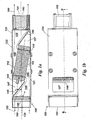
- Shown in figure 1 a is a cross-sectional view of a fuel cell assembly 100 comprising a fuel cell stack 110 mounted within an enclosure 120.
- the stack 110 is mounted at an angle ⁇ of preferably between 5 and 45 degrees to the longitudinal axis 130 of the enclosure 120, with a particular preferred angle being around 8.5 degrees.
- This mounting arrangement results in a first tapered air volume 140 between a first face 111 of the stack 110 and a first wall 121 of the enclosure, and a second tapered air volume 150 between a second face 112 of the stack 110 and a second wall 122 of the enclosure 120.
- the first and second tapered air volumes 140, 150 form part of an air flow path 160 between an air inlet 180 and an air exhaust 190 of the enclosure 120.
- the enclosure 120 may additionally provide part of the structure of the stack 110, for example taking the place of tie bolts that would otherwise be provided to clamp the end plates in position.
- the tapered air volumes 140, 150 either side of the stack 110 act to reduce the pressure drop in the air flow path leading through the stack, and improves the distribution of air in the fuel cells making up the stack 110.
- Cover plates 146, 156 may be provided in the enclosure 120 to form tapering inlet and outlet manifolds 145, 155 leading to and from the stack 110.
- the cover plates may be planar, as shown in figure 1a , or alternatively may be curved to form a desired shape of air flow path leading to and away from the stack 110.
- the cover plates 146, 156 are preferably sealed against diagonally opposing edges of the stack 110 and against the internal faces of the enclosure 120, in order to prevent leakage of air from the air flow coolant path 160.
- One or both of the cover plates 146, 156 may be formed as part of the cross-sectional shape of the enclosure 120.
- Internal volumes 147, 157 provided by the cover plates 146, 156 could be used to contain other components of the fuel cell assembly, for example relating to electrical connections, and/or regulation of the fuel supply, to the stack 110.
- Internal volume 147 is additionally shown in figure 1b , beneath an opening in a face of the enclosure 120 provided to allow access to connections 148 on the fuel cell stack 110.
- Air which for an open cathode stack acts as both coolant and oxidant, enters the enclosure 120 through a filter 185 and into the tapered inlet manifold 145 before entering the first tapered air volume 140 leading to a first face 111 of the stack 110.
- the air passes through the stack 110 and out from the second face 112 into the second tapered volume 150 above the stack.
- the air then passes through the outlet manifold 155 and is drawn out of the enclosure through one or more fans 195.
- the cells are preferably aligned to be parallel to the longitudinal axis 130 of the enclosure 120, as shown more clearly in figure 2 .
- Other arrangements where the cells are aligned laterally to the longitudinal axis 13, as for example shown in figures 5 and 6 are however, also possible.
- the layout shown in figures 1 a and 1 b allows for the total height and the overall volume of the fuel cell assembly to be reduced and allows for a more rugged package with a minimum number of components.
- Selection of the angle of the fuel cell stack 110 to the longitudinal axis of the enclosure allows for optimisation of the space used within the enclosure, both in terms of the inlet and outlet manifolds and the space required for other components.
- Figure 2 shows a perspective cutaway view of the fuel cell stack 110 and enclosure 120, illustrating the cover plates 146, 156 forming the inlet and outlet manifolds 145, 155 and further volumes 147, 157.
- Figure 3 shows a perspective view of the assembled enclosure 120.
- the regular cuboid shape of the enclosure in combination with the air inlet 180 and outlet 190 being provided at opposing ends of the enclosure 120, allows the fuel cell assembly 100 to be provided in a modular form, i.e. allowing a plurality of such fuel cell modules to be connected together physically and electrically.
- An exemplary arrangement of this is shown in the perspective view of such a modular assembly in figure 4 , illustrating a rectangular array 400 of eight such modules.
- An advantage of such an array 400 is that manufacturing costs can be minimised across a range of applications requiring different levels of electrical power.
- the present invention is particularly suitable for open cathode air-cooled designs of fuel cell stacks, other fuel cell stacks where air flow through the stack is an important feature may be incorporated into an enclosure of the type described herein.
- Shown in figure 5 is an alternative arrangement of a fuel cell stack 510.
- the stack 510 comprises a staggered array of fuel cells 520, with opposing parallel end plates 530a, 530b laterally offset from one another:
- the arrangement shown can thereby be mounted within an enclosure with the end plates 530a, 530b arranged orthogonally to opposing faces of the enclosure.
- the arrangement is shown in cross-sectional view in figure 6 , with the end plates 530a, 530b shown in relation to side walls 610a, 610b of the enclosure, with tapered air volumes 640, 650 provided between the stack 510 and side walls 610a, 610b.
- Other components making up a fuel cell assembly with the arrangement shown in figures 5 and 6 may be similar to those illustrated in figures 1 a to 4.
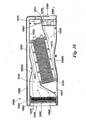
- FIG. 10 illustrates in cross-section a further alternative example of a fuel cell assembly 1000.
- the fuel cell stack 1010 is mounted and oriented within the enclosure 1020 in a similar way to the assemblies described above, but with some modifications to the form of the enclosure 1020 to improve air flow through the stack 1010 and allow for air recirculation when required.
- Air flow through the enclosure 1020 is indicated by arrows 1060, showing air entering the enclosure 1020 through an air inlet 1080 (optionally comprising an air filter 1085), through a tapering air inlet volume 1040, entering a first face 1011 of the stack 1010, exiting the stack 1010 through a second opposing face 1012 into a tapered air outlet volume 1050, and out from the enclosure 1020 through an air outlet 1090, optionally provided with a fan 1095.
- the air outlet 1090 cross-section in the example shown in figure 10 is smaller than that of the air inlet 1090 so as to allow for an air recirculation path, described in more detail below.
- Flow correctors 1030a, 1030b are provided along opposing internal side walls 1021, 1022 of the enclosure 1020, the flow correctors facing opposing faces 1011, 1012 of the stack 1010.
- the flow correctors 1030a, 1030b are in the form of narrowed portions of the internat volume defined by the opposing internal side walls of the enclosure 1020, the flow correctors being configured to provide a further tapering of the air inlet volume 1040 and air outlet volume 1050 adjacent either face 1011, 1012 of the stack 1010. The effect of this further tapering is to redistribute air flow through the stack 1010 across the inlet and outlet faces 1011, 1012, allowing a more even distribution of air flow across the stack 1010.
- An air recirculation path is provided in the assembly 1000, connecting the air outlet 1090 with the air inlet 1080 by means of a recirculation duct 1092.
- a retractable baffle 1091 is provided adjacent the air outlet 1090, the baffle 1091 being operable by means of a baffle actuator 1096 for actuating the baffle between a closed position, as shown in figure 10 , and an open position in which a proportion of the air passing through the tapered air outlet volume 1050 is redirected back towards the air inlet 1080 via the recirculation duct 1092.
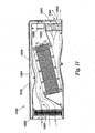
- Figure 11 shows the assembly 1000 of figure 10 with the retractable baffle 1091 in a partially open position, causing a proportion of air to be recirculated through the recirculation duct 1092 (indicated by arrow 1061) towards the air inlet 1080.
- the recirculated air exits the recirculation duct 1092 through one or more holes 1093 provided adjacent the air inlet 1080, the holes 1093 being for example in the form of a series of perforations.
- a portion of the retractable baffle 1091 extends across a face of the fan 1095 to force air into the recirculation duct 1092.
- the baffle 1091 is preferabiy slidably actuated across air outlet 1090, and comprises a curved end portion 1094 configured to direct air into the recirculation duct 1092.
- One or more baffle actuators 1096 are provided to operate the baffle 1091 between the closed and open positions.
- the actuator 1096 may, for example, be a linear or rotary actuator, arranged to slidably actuate the baffle 1091 across the air outlet 1090.
- baffle 1091 With the baffle 1091 in the closed position shown in figure 10 , air passes through the fuel cell stack and provides oxygen and cooling during normal operation. With the baffle in the open position shown in figure 11 , recirculation of air through the recirculation duct 1092 allows air that has been heated by passing through the stack 1010 to further heat the stack, for example during a cold start-up procedure. Once a measured temperature of the stack reaches a desired threshold, the baffle 1091 can be caused to retract and allow for cooling of the stack. The baffle 1091 may also be operated in a partially open position, for example during a gradual transition from a cold start to normal operation.
- FIG. 13 An alternative fuel cell assembly 1300 example is shown in figure 13 , in which an air deflector assembly 1310 is provided in the form of a regular series of curved vanes across the inlet face 1011 of the stack 1010, the curved shape of the vanes being configured to deflect air flowing through the tapered air inlet volume towards portions of the face 1011 or the stack 1010.
- a further alternative fuel cell assembly example 1400 is shown in figure 14 , in which a deflector assembly 1410a is provided in the form of a series of curved vanes providing multiple parallel flow paths between the air inlet and the first face 1011 of the stack 1010.
- a corresponding air deflector assembly 1410b is also optionally provided on the outlet face of the stack, providing multiple parallel flow paths between the outlet face 1012 of the stack 1010 and the air outlet 1090.
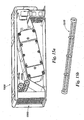
- FIG. 15a An alternative type of air deflector assembly is illustrated in the fuel cell assembly embodiment 1500 shown in figure 15a .
- the air deflector is in the form of one or more rotatable blade assemblies 1510a, 1510b, each assembly being configured to be driven by the incoming air stream from the air inlet 1080 so as to convert an inlet air flow from being relatively laminar to a more turbulent flow.
- Each blade assembly 1510a, 1510b is oriented such that the rotation axis is substantially orthogonal to the direction of air flow from the air inlet 1080.
- the more turbulent air flow in the tapered air inlet volume assists in reducing preferential air flow through particular channels in the stack.
- a further view of a single air deflector 1510 is shown in figure 15b , the deflector being in the form of a circular cylindrical element having a plurality of vanes extending longitudinally along the axis of the cylinder.
Description
- The invention relates to fuel cell assemblies, in particular to enclosures for mounting open cathode fuel cell stacks.
- Conventional electrochemical fuel cells convert fuel and oxidant, generally both in the form of gaseous streams, into electrical energy and a reaction product. A common type of electrochemical fuel cell for reacting hydrogen and oxygen comprises a polymeric ion (proton) transfer membrane, with fuel and air being passed over each side of the membrane. Protons (i.e. hydrogen ions) are conducted through the membrane, balanced by electrons conducted through a circuit connecting the anode and cathode of the fuel cell. To increase the available voltage, a stack may be formed comprising a number of such membranes arranged with separate anode and cathode fluid flow paths. Such a stack is typically in the form of a block comprising numerous individual fuel cell plates held together by end plates at either end of the stack.
- Because the reaction of fuel and oxidant generates heat as well as electrical power, a fuel cell stack requires cooling once an operating temperature has been reached. Cooling may be achieved by forcing air through the cathode fluid flow paths. In an open cathode stack, the oxidant flow path and the coolant path are the same, i.e. forcing air through the stack both supplies oxidant to the cathodes and cools the stack.
- In order to integrate a fuel cell stack with other equipment for the stack to provide power to, the stack may be provided as an integrated assembly, having integrated air and fuel lines and electrical outlet connections. The assembly requires coolant paths, which may be the same or different to the oxidant flow paths, typically provided by manifolds leading to and from the stack. Particular care needs to be taken on how the air flow interfaces with the cathode flow paths, so that a uniform air flow and minimal pressure drop is achieved. Designing such manifolds can lead to increased complexity and cost of the operational unit.
- A further complication is the need to design a different fuel cell assembly for each different application, since each application will tend to have its own power requirements in terms of required voltages and currents as well as space. Redesigning the assembly for each application can add considerably to the cost of each implementation.
-
JP 2003/036878 A -
WO 02/053402 A1 - It is an object of the present invention to address one or more of the above mentioned problems.
- In accordance with the invention there is provided a fuel cell assembly comprising:
- an enclosure for mounting a fuel cell stack therein, the enclosure comprising an air flow path extending between an air inlet and an air outlet; and
- a fuel cell stack having a plurality of cathode air coolant paths extending between a first face and an opposing second face of the stack,
- wherein the fuel cell stack is mounted within the enclosure to provide a tapering air volume between the first face of the stack and a first side wall of the enclosure and between the second face of the stack and a second opposing side wall of the enclosure, and
- an air deflector assembly provided between the air inlet and first face of the fuel cell stack;
- wherein the air deflector assembly comprises a plurality of vanes arranged to direct air towards one or more portions of the inlet face of the fuel cell stack; and
- wherein the plurality of vanes are arranged as one or more rotatable air deflector assemblies configured to rotate in response to air flowing through the air inlet to increase turbulence in the tapered air inlet volume.
- An advantage of the fuel cell assembly according to the disclosure is that, because tapering air volumes are provided by the relative arrangement of the enclosure and the faces of the stack, specially designed manifolds are not required, thereby reducing the complexity and cost of the overall assembly.
- Diagonally opposing edges of the stack can be sealed against the respective first and second opposing side walls of the enclosure, to allow for a sealed air flow path through the enclosure.
- The enclosure may comprise an inlet air filter at a first end of the air flow path and an air exhaust at a second opposing end. This helps to reduce the overall height and width of the assembly. A reducing tapered section may be incorporated, extending from the inlet air filter to the first tapered air volume, to improve uniformity of air flow to the stack.
- An increasing tapered section may also be provided extending from the second tapered air volume to the air exhaust, so as to improve air flow and reduce any pressure drop across the assembly.
- A fan may be provided at the air exhaust for drawing air through the air flow path. The fan may alternatively be provided at the air inlet for blowing air through the air flow path.
- The enclosure may have a substantially cuboid external shape, which allows multiple assemblies to be stacked on top of one another, for increasing the power available from the stacks.
- The fuel-cell stack may be mounted within the enclosure at an angle of between 5 and 45 degrees to a longitudinal axis of the enclosure. This preferred range of angles allows for air flow to be uniformly distributed along the stack, while keeping the additional height required for the enclosure to a minimum. A particular preferred angle is around 8.5 degrees.
- The fuel cell stack may in certain examples comprise a staggered array of planar fuel cells between opposing end plates laterally offset from one another. Alternatively, the stack may be substantially cuboid in shape, with the end plates in line with each other and the stack having a uniform cross-section between the end plates.
- The fuel cell stack may alternatively have a cross-sectional shape in the form of a parallelogram
- In preferred examples, including those where the cross-sectional shape of the stack is other than rectangular as well as those where the stack is substantially cuboid in shape, planar fuel cells making up the fuel cell stack are aligned parallel to the longitudinal axis of the enclosure. Aligning the cells parallel, rather than laterally, to the enclosure axis allows for a more uniform pressure distribution across stack, thereby ensuring that air flow through the stack is more uniform.
- The fuel cell assembly optionally comprises an air recirculation duct extending between the air outlet and air inlet, the assembly comprising a retractable baffle adjacent the air outlet, the baffle being operable between a closed position and an open position in which a proportion of air passing through the second tapering air volume is redirected back towards the air inlet via the recirculation duct.
- A modular fuel cell assembly may be constructed from a plurality of the fuel cell assemblies according to the invention, with the assemblies arranged in a regular array. The regular array may be a rectangular array.
- The invention will now be described by way of example, and with reference to the enclosed drawings in which:
-
figure 1a is a cross-sectional view of an enclosure with a fuel cell stack mounted therein; -
figure 1b is a plan view of the enclosure offigure 1a ; -
figure 2 is a cut-away perspective view of an enclosure with a fuel cell stack mounted therein; -
figure 3 is a perspective view of the enclosure offigure 2 ; -
figure 4 is a perspective view of a modular assembly of enclosures containing fuel cell stacks; -
figure 5 is a perspective view of an alternative fuel cell stack; -
figure 6 is a cross-sectional view of the alternative fuel cell stack offigure 5 mounted between opposing side walls of an enclosure; -
figure 7 is a perspective partially transparent view of a further alternative form of fuel cell assembly; -
figure 8 is a cross-sectional view of the further alternative form of fuel cell assembly: -
figure 9 is an end elevation view of the further alternative form of fuel cell assembly; -
figure 10 is a cross-sectional drawing of a further alternative example, having an air recirculation path in a closed / non-recirculating configuration; -
figure 11 is a cross-sectional drawing of the further alternative example offigure 10 , with the air recirculation path in a partially open/recirculating configuration; -
figure 12 is a perspective drawing of a further alternative example, having a first type of air inlet deflector in the air inlet manifold; -
figure 13 is a perspective drawing of a further alternative example, having a second type of air inlet deflector in the air inlet manifold; -
figure 14 is a perspective drawing of a further alternative example, having a third type of air inlet deflector in the air inlet manifold together with an air outlet manifold; -
figure 15a is a perspective drawing of an embodiment, having a fourth type of air inlet deflector in the air inlet manifold; and -
figure 15b is a perspective drawing of a rotatable air deflector for use in the embodiment offigure 15a . - Shown in
figure 1 a is a cross-sectional view of afuel cell assembly 100 comprising afuel cell stack 110 mounted within anenclosure 120. Thestack 110 is mounted at an angle θ of preferably between 5 and 45 degrees to thelongitudinal axis 130 of theenclosure 120, with a particular preferred angle being around 8.5 degrees. This mounting arrangement results in a firsttapered air volume 140 between afirst face 111 of thestack 110 and afirst wall 121 of the enclosure, and a secondtapered air volume 150 between asecond face 112 of thestack 110 and asecond wall 122 of theenclosure 120. The first and secondtapered air volumes air flow path 160 between anair inlet 180 and anair exhaust 190 of theenclosure 120. A reducing taperedinlet manifold 145 extends between anair filter 185 at the air inlet and the firsttapered air volume 140. An increasing taperedoutlet manifold 155 extends between the secondtapered air volume 150 and afan 195 provided at theair exhaust 180. Thefan 195 may alternatively be provided at theair inlet 180 to blow air through theenclosure 120. - The
enclosure 120 may additionally provide part of the structure of thestack 110, for example taking the place of tie bolts that would otherwise be provided to clamp the end plates in position. - The
tapered air volumes stack 110 act to reduce the pressure drop in the air flow path leading through the stack, and improves the distribution of air in the fuel cells making up thestack 110. -
Cover plates enclosure 120 to form tapering inlet and outlet manifolds 145, 155 leading to and from thestack 110. The cover plates may be planar, as shown infigure 1a , or alternatively may be curved to form a desired shape of air flow path leading to and away from thestack 110. Thecover plates stack 110 and against the internal faces of theenclosure 120, in order to prevent leakage of air from the airflow coolant path 160. One or both of thecover plates enclosure 120. Furtherinternal volumes cover plates stack 110.Internal volume 147 is additionally shown infigure 1b , beneath an opening in a face of theenclosure 120 provided to allow access toconnections 148 on thefuel cell stack 110. - Air, which for an open cathode stack acts as both coolant and oxidant, enters the
enclosure 120 through afilter 185 and into the taperedinlet manifold 145 before entering the firsttapered air volume 140 leading to afirst face 111 of thestack 110. The air passes through thestack 110 and out from thesecond face 112 into the secondtapered volume 150 above the stack. The air then passes through theoutlet manifold 155 and is drawn out of the enclosure through one ormore fans 195. In order to ensure that a reasonably uniform air flow is provided through each of the cells making up thestack 110, the cells are preferably aligned to be parallel to thelongitudinal axis 130 of theenclosure 120, as shown more clearly infigure 2 . Other arrangements where the cells are aligned laterally to the longitudinal axis 13, as for example shown infigures 5 and6 , are however, also possible. - At least in relation to open cathode air-cooled fuel cell stacks, the layout shown in
figures 1 a and 1 b allows for the total height and the overall volume of the fuel cell assembly to be reduced and allows for a more rugged package with a minimum number of components. Selection of the angle of thefuel cell stack 110 to the longitudinal axis of the enclosure allows for optimisation of the space used within the enclosure, both in terms of the inlet and outlet manifolds and the space required for other components. -
Figure 2 shows a perspective cutaway view of thefuel cell stack 110 andenclosure 120, illustrating thecover plates further volumes -
Figure 3 shows a perspective view of the assembledenclosure 120. The regular cuboid shape of the enclosure, in combination with theair inlet 180 andoutlet 190 being provided at opposing ends of theenclosure 120, allows thefuel cell assembly 100 to be provided in a modular form, i.e. allowing a plurality of such fuel cell modules to be connected together physically and electrically. An exemplary arrangement of this is shown in the perspective view of such a modular assembly infigure 4 , illustrating arectangular array 400 of eight such modules. An advantage of such anarray 400 is that manufacturing costs can be minimised across a range of applications requiring different levels of electrical power. Although the present invention is particularly suitable for open cathode air-cooled designs of fuel cell stacks, other fuel cell stacks where air flow through the stack is an important feature may be incorporated into an enclosure of the type described herein. - Shown in
figure 5 is an alternative arrangement of afuel cell stack 510. Thestack 510 comprises a staggered array offuel cells 520, with opposingparallel end plates end plates figure 6 , with theend plates side walls tapered air volumes stack 510 andside walls figures 5 and6 may be similar to those illustrated infigures 1 a to 4. -
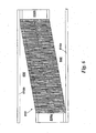
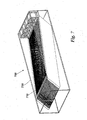
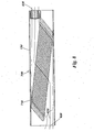
Figure 7 shows a further alternative form offuel cell assembly 700, in which thefuel cell stack 710 has a cross-sectional shape in the form of a parallelogram, rather than the rectangular forms shown infigures 1 a and 2.Figure 8 shows a cross-sectional view through thefuel cell stack 710, in which the alignment of each of the individual fuel cell plates can be seen. The parallelogram form of thestack 710 allows the plates to be aligned towards the air flow direction through the enclosure, indicated byair flow paths 810, thereby aiming to reduce turbulence and pressure drop between theinlet 820 andoutlet 830 of theenclosure 720. An outlet end elevation view of thefuel cell assembly 700 is shown infigure 9 , indicating the section (C-C) through whichfigure 8 is taken. -
Figure 10 illustrates in cross-section a further alternative example of afuel cell assembly 1000. Thefuel cell stack 1010 is mounted and oriented within theenclosure 1020 in a similar way to the assemblies described above, but with some modifications to the form of theenclosure 1020 to improve air flow through thestack 1010 and allow for air recirculation when required. Air flow through theenclosure 1020 is indicated byarrows 1060, showing air entering theenclosure 1020 through an air inlet 1080 (optionally comprising an air filter 1085), through a taperingair inlet volume 1040, entering afirst face 1011 of thestack 1010, exiting thestack 1010 through a second opposingface 1012 into a taperedair outlet volume 1050, and out from theenclosure 1020 through anair outlet 1090, optionally provided with afan 1095. Different to the previously described examples, theair outlet 1090 cross-section in the example shown infigure 10 is smaller than that of theair inlet 1090 so as to allow for an air recirculation path, described in more detail below. -
Flow correctors internal side walls enclosure 1020, the flow correctors facing opposingfaces stack 1010. Theflow correctors enclosure 1020, the flow correctors being configured to provide a further tapering of theair inlet volume 1040 andair outlet volume 1050 adjacent eitherface stack 1010. The effect of this further tapering is to redistribute air flow through thestack 1010 across the inlet and outlet faces 1011, 1012, allowing a more even distribution of air flow across thestack 1010. - An air recirculation path is provided in the
assembly 1000, connecting theair outlet 1090 with theair inlet 1080 by means of arecirculation duct 1092. Aretractable baffle 1091 is provided adjacent theair outlet 1090, thebaffle 1091 being operable by means of abaffle actuator 1096 for actuating the baffle between a closed position, as shown infigure 10 , and an open position in which a proportion of the air passing through the taperedair outlet volume 1050 is redirected back towards theair inlet 1080 via therecirculation duct 1092. -
Figure 11 shows theassembly 1000 offigure 10 with theretractable baffle 1091 in a partially open position, causing a proportion of air to be recirculated through the recirculation duct 1092 (indicated by arrow 1061) towards theair inlet 1080. The recirculated air exits therecirculation duct 1092 through one ormore holes 1093 provided adjacent theair inlet 1080, theholes 1093 being for example in the form of a series of perforations. In the configuration shown infigure 11 , a portion of theretractable baffle 1091 extends across a face of thefan 1095 to force air into therecirculation duct 1092. Thebaffle 1091 is preferabiy slidably actuated acrossair outlet 1090, and comprises acurved end portion 1094 configured to direct air into therecirculation duct 1092. - One or
more baffle actuators 1096 are provided to operate thebaffle 1091 between the closed and open positions. Theactuator 1096 may, for example, be a linear or rotary actuator, arranged to slidably actuate thebaffle 1091 across theair outlet 1090. - With the
baffle 1091 in the closed position shown infigure 10 , air passes through the fuel cell stack and provides oxygen and cooling during normal operation. With the baffle in the open position shown infigure 11 , recirculation of air through therecirculation duct 1092 allows air that has been heated by passing through thestack 1010 to further heat the stack, for example during a cold start-up procedure. Once a measured temperature of the stack reaches a desired threshold, thebaffle 1091 can be caused to retract and allow for cooling of the stack. Thebaffle 1091 may also be operated in a partially open position, for example during a gradual transition from a cold start to normal operation. - Shown in
figure 12 is an alternative example similar to theassembly 1000 offigures 10 and11 , in which anair deflector assembly 1210 is provided within the taperedair inlet volume 1040 in place of theflow correctors curved vanes 1211 configured to redirect air from the tapered air inlet volume across theinlet face 1011 of thestack 1010, thereby redistributing air flow across theinlet face 1010. - An alternative
fuel cell assembly 1300 example is shown infigure 13 , in which anair deflector assembly 1310 is provided in the form of a regular series of curved vanes across theinlet face 1011 of thestack 1010, the curved shape of the vanes being configured to deflect air flowing through the tapered air inlet volume towards portions of theface 1011 or thestack 1010. - A further alternative fuel cell assembly example 1400 is shown in
figure 14 , in which adeflector assembly 1410a is provided in the form of a series of curved vanes providing multiple parallel flow paths between the air inlet and thefirst face 1011 of thestack 1010. A correspondingair deflector assembly 1410b is also optionally provided on the outlet face of the stack, providing multiple parallel flow paths between theoutlet face 1012 of thestack 1010 and theair outlet 1090. - An alternative type of air deflector assembly is illustrated in the fuel
cell assembly embodiment 1500 shown infigure 15a . The air deflector is in the form of one or morerotatable blade assemblies air inlet 1080 so as to convert an inlet air flow from being relatively laminar to a more turbulent flow. Eachblade assembly air inlet 1080. The more turbulent air flow in the tapered air inlet volume assists in reducing preferential air flow through particular channels in the stack. A further view of asingle air deflector 1510 is shown infigure 15b , the deflector being in the form of a circular cylindrical element having a plurality of vanes extending longitudinally along the axis of the cylinder. - Other embodiments are intentionally within the scope of the invention as defined by the appended claims.
Claims (12)
- A fuel cell assembly (100) comprising:an enclosure (120) for mounting a fuel cell stack (110) therein, the enclosure comprising an air flow path (160) extending between an air inlet (180) and an air outlet (190);a fuel cell stack (110) having a plurality of cathode air coolant paths extending between a first face (111) and an opposing second face (112) of the stack,wherein the fuel cell stack is mounted within the enclosure to provide a first tapering air volume (140) between the first face (111) of the stack and a first side wall (121) of the enclosure and a second tapering air volume (150) between the second face (112) of the stack and a second opposing side wall (122) of the enclosure, andan air deflector assembly (1510a, 1510b) provided between the air inlet (1080) and first face (1011) of the fuel cell stack;wherein the air deflector assembly comprises a plurality of vanes (1211) arranged to direct air towards one or more portions of the inlet face (1011) of the fuel cell stack (1010); andwherein the plurality of vanes (1211) are arranged as one or more rotatable air deflector assemblies (1510a, b) configured to rotate in response to air flowing through the air inlet (1080) to increase turbulence in the tapered air inlet volume (1040).
- The fuel cell assembly of claim 1 wherein diagonally opposing edges of the stack (110) are sealed against the respective first and second opposing side walls of the enclosure (120).
- The fuel cell assembly of claim 1 wherein the enclosure comprises an inlet air filter (185) at a first end of the air flow path and an air exhaust (190) at a second opposing end.
- The fuel cell assembly of claim 3 comprising a reducing tapered section (145) extending from the inlet air filter (185) to the first tapered air volume (140).
- The fuel cell assembly of claim 3 or claim 4 comprising a increasing tapered section (155) extending from the second tapered air volume (150) to the air exhaust (190).
- The fuel cell assembly of any one of claims 3 to 5 comprising a fan (195) provided at the air exhaust (190) for drawing air through the air flow path.
- The fuel cell assembly of any one of claims 1 to 6 wherein the enclosure has a substantially cuboid external shape.
- The fuel cell assembly of any preceding claim wherein the fuel cell stack is mounted at an angle of between 5 and 45 degrees to a longitudinal axis of the enclosure.
- The fuel cell assembly of any one of claims 1 to 7 wherein the fuel cell stack comprises a staggered array of planar fuel cells between opposing end plates laterally offset from one another.
- The fuel cell assembly of any one of claims 1 to 7 wherein the fuel cell stack has a cross-sectional shape in the form of a parallelogram.
- The fuel cell assembly of any preceding claim comprising an air recirculation duct (1092) extending between the air outlet (1090) and air inlet (1080), the assembly comprising a retractable baffle (1091) adjacent the air outlet (1090), the baffle (1091) being operable between a closed position and an open position in which a proportion of air passing through the second tapering air volume (1050) is redirected back towards the air inlet (1080) via the recirculation duct (1092).
- A modular fuel cell assembly comprising a plurality of fuel cell assemblies according to any one of claims 1 to 11 arranged in a regular array, the array being optionally a rectangular array.
Applications Claiming Priority (2)
| Application Number | Priority Date | Filing Date | Title |
|---|---|---|---|
| GB0818320A GB2464274A (en) | 2008-10-07 | 2008-10-07 | Fuel Cell Assembly |
| PCT/GB2009/002402 WO2010041013A1 (en) | 2008-10-07 | 2009-10-07 | Fuel cell assembly |
Publications (2)
| Publication Number | Publication Date |
|---|---|
| EP2338202A1 EP2338202A1 (en) | 2011-06-29 |
| EP2338202B1 true EP2338202B1 (en) | 2015-07-22 |
Family
ID=40042389
Family Applications (1)
| Application Number | Title | Priority Date | Filing Date |
|---|---|---|---|
| EP09740925.4A Not-in-force EP2338202B1 (en) | 2008-10-07 | 2009-10-07 | Fuel cell assembly |
Country Status (12)
| Country | Link |
|---|---|
| US (2) | US20100086810A1 (en) |
| EP (1) | EP2338202B1 (en) |
| JP (1) | JP5438767B2 (en) |
| KR (1) | KR20110081191A (en) |
| CN (1) | CN102177610B (en) |
| AR (1) | AR073782A1 (en) |
| BR (1) | BRPI0920886A2 (en) |
| CA (1) | CA2738738A1 (en) |
| GB (1) | GB2464274A (en) |
| MX (1) | MX2011003673A (en) |
| TW (1) | TWI469436B (en) |
| WO (1) | WO2010041013A1 (en) |
Cited By (1)
| Publication number | Priority date | Publication date | Assignee | Title |
|---|---|---|---|---|
| WO2020018832A1 (en) * | 2018-07-20 | 2020-01-23 | Ballard Power Systems Inc. | Air cooling arrangement for a co-axial array of fuel cell stacks |
Families Citing this family (14)
| Publication number | Priority date | Publication date | Assignee | Title |
|---|---|---|---|---|
| JP4434279B2 (en) * | 2007-12-26 | 2010-03-17 | トヨタ自動車株式会社 | Fuel cell system |
| KR100862924B1 (en) * | 2008-07-14 | 2008-10-13 | 황부성 | A hydrogen-oxygen generating apparatus |
| JP5585378B2 (en) * | 2010-10-21 | 2014-09-10 | スズキ株式会社 | Air-cooled fuel cell vehicle |
| GB2499412A (en) * | 2012-02-15 | 2013-08-21 | Intelligent Energy Ltd | A fuel cell assembly |
| GB2499417A (en) * | 2012-02-15 | 2013-08-21 | Intelligent Energy Ltd | A fuel cell assembly |
| GB2501700A (en) | 2012-05-01 | 2013-11-06 | Intelligent Energy Ltd | Fuel cell stack assembly |
| WO2014028001A1 (en) * | 2012-08-14 | 2014-02-20 | Empire Technology Development Llc | Flexible transparent air-metal batteries |
| GB2505963B (en) * | 2012-09-18 | 2021-04-07 | Intelligent Energy Ltd | A fuel cell stack assembly |
| KR101372203B1 (en) * | 2012-12-24 | 2014-03-07 | 현대자동차주식회사 | Thermal management system for fuel cell stack |
| WO2014131693A1 (en) * | 2013-02-27 | 2014-09-04 | Bayerische Motoren Werke Aktiengesellschaft | Fuel cell system |
| GB2514145A (en) * | 2013-05-15 | 2014-11-19 | Intelligent Energy Ltd | Cooling system for fuel cells |
| SE540633C2 (en) * | 2016-01-27 | 2018-10-09 | Powercell Sweden Ab | Fuel cell stack housing |
| KR20180096986A (en) * | 2017-02-22 | 2018-08-30 | 말레 인터내셔널 게엠베하 | Fuel cell stack |
| JP7156251B2 (en) * | 2019-11-13 | 2022-10-19 | トヨタ自動車株式会社 | Fuel cell drying method and fuel cell drying apparatus |
Family Cites Families (25)
| Publication number | Priority date | Publication date | Assignee | Title |
|---|---|---|---|---|
| US4324844A (en) * | 1980-04-28 | 1982-04-13 | Westinghouse Electric Corp. | Variable area fuel cell cooling |
| JPH01281682A (en) * | 1988-05-09 | 1989-11-13 | Toshiba Corp | Fuel cell |
| JP3509517B2 (en) * | 1997-12-18 | 2004-03-22 | 本田技研工業株式会社 | Cooling structure of battery and electric parts in electric vehicle |
| EP1293006A2 (en) * | 2000-03-17 | 2003-03-19 | Allen Engineering Company, Inc. | Fuel cell stack assembly |
| DE10065307A1 (en) * | 2000-12-29 | 2002-07-11 | Siemens Ag | Fuel cell system for a motor vehicle |
| DE10112074A1 (en) * | 2001-03-12 | 2002-10-02 | Forschungszentrum Juelich Gmbh | Fuel cell with even distribution of equipment |
| JP2002373709A (en) * | 2001-06-15 | 2002-12-26 | Denso Corp | Battery cooling structure |
| JP2003036878A (en) * | 2001-07-19 | 2003-02-07 | Equos Research Co Ltd | Air supply system for fuel cell |
| US6679280B1 (en) * | 2001-10-19 | 2004-01-20 | Metallic Power, Inc. | Manifold for fuel cell system |
| JP2004207019A (en) * | 2002-12-25 | 2004-07-22 | Nissan Motor Co Ltd | Fuel cell |
| JP4127111B2 (en) * | 2003-04-22 | 2008-07-30 | 日産自動車株式会社 | Fuel cell system |
| JP2004335307A (en) * | 2003-05-08 | 2004-11-25 | Nissan Motor Co Ltd | Fuel cell stack and fuel cell automobile |
| DE10342470A1 (en) * | 2003-09-15 | 2005-04-07 | P21 - Power For The 21St Century Gmbh | Device for flowing at least one fuel cell with a medium and fuel cell system |
| JP4576931B2 (en) * | 2004-08-27 | 2010-11-10 | トヨタ自動車株式会社 | Electrical equipment mounting structure |
| US7478629B2 (en) * | 2004-11-04 | 2009-01-20 | Del Valle Bravo Facundo | Axial flow supercharger and fluid compression machine |
| US20060228618A1 (en) * | 2005-04-12 | 2006-10-12 | Keegan Kevin R | Cathode air baffle for a fuel cell |
| JP2007095491A (en) * | 2005-09-29 | 2007-04-12 | Equos Research Co Ltd | Fuel cell system |
| EP1777770B1 (en) * | 2005-10-20 | 2010-08-25 | Samsung SDI Co., Ltd. | Semi-Passive Type Fuel Cell System |
| KR101255236B1 (en) * | 2006-01-27 | 2013-04-16 | 삼성에스디아이 주식회사 | Direct liquid feed fuel cell system |
| JP4971781B2 (en) * | 2006-03-07 | 2012-07-11 | 本田技研工業株式会社 | Refrigerant manifold, refrigerant supply method, and refrigerant discharge method |
| JP5146765B2 (en) * | 2006-03-22 | 2013-02-20 | 日本電気株式会社 | Fuel cell system |
| GB2442252B (en) * | 2006-09-27 | 2010-10-27 | Intelligent Energy Ltd | Low temperature operation of open cathode fuel cell stacks using air recirculation |
| US20080085437A1 (en) * | 2006-09-29 | 2008-04-10 | Dean James F | Pleated heat and humidity exchanger with flow field elements |
| DE102006049031B4 (en) * | 2006-10-13 | 2009-10-22 | Futuree Fuel Cell Solutions Gmbh | Carrying container of a power supply unit with fuel cells, its use and method for risk reduction |
| DE102008020762A1 (en) * | 2008-04-18 | 2009-10-22 | Heliocentris Energiesysteme Gmbh | The fuel cell system |
-
2008
- 2008-10-07 GB GB0818320A patent/GB2464274A/en not_active Withdrawn
-
2009
- 2009-02-26 US US12/393,991 patent/US20100086810A1/en not_active Abandoned
- 2009-10-06 TW TW98133780A patent/TWI469436B/en not_active IP Right Cessation
- 2009-10-07 MX MX2011003673A patent/MX2011003673A/en active IP Right Grant
- 2009-10-07 JP JP2011529623A patent/JP5438767B2/en not_active Expired - Fee Related
- 2009-10-07 CA CA2738738A patent/CA2738738A1/en not_active Abandoned
- 2009-10-07 CN CN200980139165.4A patent/CN102177610B/en not_active Expired - Fee Related
- 2009-10-07 BR BRPI0920886A patent/BRPI0920886A2/en not_active IP Right Cessation
- 2009-10-07 WO PCT/GB2009/002402 patent/WO2010041013A1/en active Application Filing
- 2009-10-07 US US13/122,566 patent/US20110269043A1/en not_active Abandoned
- 2009-10-07 AR ARP090103854A patent/AR073782A1/en not_active Application Discontinuation
- 2009-10-07 KR KR1020117008211A patent/KR20110081191A/en not_active Application Discontinuation
- 2009-10-07 EP EP09740925.4A patent/EP2338202B1/en not_active Not-in-force
Cited By (1)
| Publication number | Priority date | Publication date | Assignee | Title |
|---|---|---|---|---|
| WO2020018832A1 (en) * | 2018-07-20 | 2020-01-23 | Ballard Power Systems Inc. | Air cooling arrangement for a co-axial array of fuel cell stacks |
Also Published As
| Publication number | Publication date |
|---|---|
| EP2338202A1 (en) | 2011-06-29 |
| BRPI0920886A2 (en) | 2015-12-22 |
| TW201015771A (en) | 2010-04-16 |
| GB0818320D0 (en) | 2008-11-12 |
| JP2012505496A (en) | 2012-03-01 |
| US20100086810A1 (en) | 2010-04-08 |
| AR073782A1 (en) | 2010-12-01 |
| GB2464274A (en) | 2010-04-14 |
| TWI469436B (en) | 2015-01-11 |
| CA2738738A1 (en) | 2010-04-15 |
| JP5438767B2 (en) | 2014-03-12 |
| KR20110081191A (en) | 2011-07-13 |
| WO2010041013A8 (en) | 2011-05-05 |
| CN102177610A (en) | 2011-09-07 |
| CN102177610B (en) | 2014-12-03 |
| US20110269043A1 (en) | 2011-11-03 |
| WO2010041013A1 (en) | 2010-04-15 |
| MX2011003673A (en) | 2011-05-02 |
Similar Documents
| Publication | Publication Date | Title |
|---|---|---|
| EP2338202B1 (en) | Fuel cell assembly | |
| US7923162B2 (en) | Fuel cell assemblies with integrated reactant-conditioning heat exchangers | |
| US10062913B2 (en) | Fuel cell components, stacks and modular fuel cell systems | |
| US20020071981A1 (en) | Fuel cell | |
| KR102102284B1 (en) | Cooling system for fuel cells | |
| US8883362B2 (en) | Fuel cell system | |
| WO2007017722A1 (en) | Humidifying system for a fuel cell | |
| KR101107649B1 (en) | Fuel cell and electronic equipment mounting it | |
| US8808938B2 (en) | Fuel cell system | |
| US20090053570A1 (en) | Fuel cell stack for low temperature start-up and operation | |
| CA2437536C (en) | Fuel cell and method of operating the same | |
| US20100279189A1 (en) | Fuel cell system | |
| EP3824506B1 (en) | Fuel cell system and integration backplane for fuel cell modules | |
| US20220333613A1 (en) | Centrifugal blower with integrated motor and blower volute which functions as a heat sink for the motor | |
| JP4443830B2 (en) | Method for operating a fuel cell in a minimum or partial load range | |
| KR101187114B1 (en) | Air Cooling Type Fuel Cell | |
| KR20240051734A (en) | Fuel cell system | |
| KR20150036621A (en) | Fuel cell coolant flowfield configuration | |
| US20230378486A1 (en) | Bipolar plate with media regulation and fuel cell stack | |
| JP2017126472A (en) | Fuel battery | |
| WO2022152577A1 (en) | Fuel cell system and integration backplane for fuel cell modules |
Legal Events
| Date | Code | Title | Description |
|---|---|---|---|
| PUAI | Public reference made under article 153(3) epc to a published international application that has entered the european phase |
Free format text: ORIGINAL CODE: 0009012 |
|
| 17P | Request for examination filed |
Effective date: 20110415 |
|
| AK | Designated contracting states |
Kind code of ref document: A1 Designated state(s): AT BE BG CH CY CZ DE DK EE ES FI FR GB GR HR HU IE IS IT LI LT LU LV MC MK MT NL NO PL PT RO SE SI SK SM TR |
|
| AX | Request for extension of the european patent |
Extension state: AL BA RS |
|
| DAX | Request for extension of the european patent (deleted) | ||
| RAP1 | Party data changed (applicant data changed or rights of an application transferred) |
Owner name: INTELLIGENT ENERGY LIMITED |
|
| 17Q | First examination report despatched |
Effective date: 20130326 |
|
| RIC1 | Information provided on ipc code assigned before grant |
Ipc: H01M 8/10 20060101ALN20141124BHEP Ipc: H01M 8/24 20060101AFI20141124BHEP Ipc: H01M 8/04 20060101ALI20141124BHEP |
|
| GRAP | Despatch of communication of intention to grant a patent |
Free format text: ORIGINAL CODE: EPIDOSNIGR1 |
|
| INTG | Intention to grant announced |
Effective date: 20150213 |
|
| GRAS | Grant fee paid |
Free format text: ORIGINAL CODE: EPIDOSNIGR3 |
|
| GRAA | (expected) grant |
Free format text: ORIGINAL CODE: 0009210 |
|
| AK | Designated contracting states |
Kind code of ref document: B1 Designated state(s): AT BE BG CH CY CZ DE DK EE ES FI FR GB GR HR HU IE IS IT LI LT LU LV MC MK MT NL NO PL PT RO SE SI SK SM TR |
|
| REG | Reference to a national code |
Ref country code: GB Ref legal event code: FG4D |
|
| REG | Reference to a national code |
Ref country code: CH Ref legal event code: EP |
|
| REG | Reference to a national code |
Ref country code: IE Ref legal event code: FG4D |
|
| REG | Reference to a national code |
Ref country code: AT Ref legal event code: REF Ref document number: 738346 Country of ref document: AT Kind code of ref document: T Effective date: 20150815 |
|
| REG | Reference to a national code |
Ref country code: DE Ref legal event code: R096 Ref document number: 602009032357 Country of ref document: DE |
|
| REG | Reference to a national code |
Ref country code: AT Ref legal event code: MK05 Ref document number: 738346 Country of ref document: AT Kind code of ref document: T Effective date: 20150722 |
|
| REG | Reference to a national code |
Ref country code: LT Ref legal event code: MG4D |
|
| REG | Reference to a national code |
Ref country code: NL Ref legal event code: MP Effective date: 20150722 |
|
| PG25 | Lapsed in a contracting state [announced via postgrant information from national office to epo] |
Ref country code: LT Free format text: LAPSE BECAUSE OF FAILURE TO SUBMIT A TRANSLATION OF THE DESCRIPTION OR TO PAY THE FEE WITHIN THE PRESCRIBED TIME-LIMIT Effective date: 20150722 Ref country code: GR Free format text: LAPSE BECAUSE OF FAILURE TO SUBMIT A TRANSLATION OF THE DESCRIPTION OR TO PAY THE FEE WITHIN THE PRESCRIBED TIME-LIMIT Effective date: 20151023 Ref country code: NO Free format text: LAPSE BECAUSE OF FAILURE TO SUBMIT A TRANSLATION OF THE DESCRIPTION OR TO PAY THE FEE WITHIN THE PRESCRIBED TIME-LIMIT Effective date: 20151022 Ref country code: FI Free format text: LAPSE BECAUSE OF FAILURE TO SUBMIT A TRANSLATION OF THE DESCRIPTION OR TO PAY THE FEE WITHIN THE PRESCRIBED TIME-LIMIT Effective date: 20150722 Ref country code: LV Free format text: LAPSE BECAUSE OF FAILURE TO SUBMIT A TRANSLATION OF THE DESCRIPTION OR TO PAY THE FEE WITHIN THE PRESCRIBED TIME-LIMIT Effective date: 20150722 |
|
| PG25 | Lapsed in a contracting state [announced via postgrant information from national office to epo] |
Ref country code: PL Free format text: LAPSE BECAUSE OF FAILURE TO SUBMIT A TRANSLATION OF THE DESCRIPTION OR TO PAY THE FEE WITHIN THE PRESCRIBED TIME-LIMIT Effective date: 20150722 Ref country code: SE Free format text: LAPSE BECAUSE OF FAILURE TO SUBMIT A TRANSLATION OF THE DESCRIPTION OR TO PAY THE FEE WITHIN THE PRESCRIBED TIME-LIMIT Effective date: 20150722 Ref country code: ES Free format text: LAPSE BECAUSE OF FAILURE TO SUBMIT A TRANSLATION OF THE DESCRIPTION OR TO PAY THE FEE WITHIN THE PRESCRIBED TIME-LIMIT Effective date: 20150722 Ref country code: IS Free format text: LAPSE BECAUSE OF FAILURE TO SUBMIT A TRANSLATION OF THE DESCRIPTION OR TO PAY THE FEE WITHIN THE PRESCRIBED TIME-LIMIT Effective date: 20151122 Ref country code: PT Free format text: LAPSE BECAUSE OF FAILURE TO SUBMIT A TRANSLATION OF THE DESCRIPTION OR TO PAY THE FEE WITHIN THE PRESCRIBED TIME-LIMIT Effective date: 20151123 Ref country code: HR Free format text: LAPSE BECAUSE OF FAILURE TO SUBMIT A TRANSLATION OF THE DESCRIPTION OR TO PAY THE FEE WITHIN THE PRESCRIBED TIME-LIMIT Effective date: 20150722 Ref country code: AT Free format text: LAPSE BECAUSE OF FAILURE TO SUBMIT A TRANSLATION OF THE DESCRIPTION OR TO PAY THE FEE WITHIN THE PRESCRIBED TIME-LIMIT Effective date: 20150722 |
|
| REG | Reference to a national code |
Ref country code: DE Ref legal event code: R097 Ref document number: 602009032357 Country of ref document: DE |
|
| PG25 | Lapsed in a contracting state [announced via postgrant information from national office to epo] |
Ref country code: DK Free format text: LAPSE BECAUSE OF FAILURE TO SUBMIT A TRANSLATION OF THE DESCRIPTION OR TO PAY THE FEE WITHIN THE PRESCRIBED TIME-LIMIT Effective date: 20150722 Ref country code: SK Free format text: LAPSE BECAUSE OF FAILURE TO SUBMIT A TRANSLATION OF THE DESCRIPTION OR TO PAY THE FEE WITHIN THE PRESCRIBED TIME-LIMIT Effective date: 20150722 Ref country code: CZ Free format text: LAPSE BECAUSE OF FAILURE TO SUBMIT A TRANSLATION OF THE DESCRIPTION OR TO PAY THE FEE WITHIN THE PRESCRIBED TIME-LIMIT Effective date: 20150722 Ref country code: IT Free format text: LAPSE BECAUSE OF FAILURE TO SUBMIT A TRANSLATION OF THE DESCRIPTION OR TO PAY THE FEE WITHIN THE PRESCRIBED TIME-LIMIT Effective date: 20150722 Ref country code: EE Free format text: LAPSE BECAUSE OF FAILURE TO SUBMIT A TRANSLATION OF THE DESCRIPTION OR TO PAY THE FEE WITHIN THE PRESCRIBED TIME-LIMIT Effective date: 20150722 |
|
| PLBE | No opposition filed within time limit |
Free format text: ORIGINAL CODE: 0009261 |
|
| STAA | Information on the status of an ep patent application or granted ep patent |
Free format text: STATUS: NO OPPOSITION FILED WITHIN TIME LIMIT |
|
| PG25 | Lapsed in a contracting state [announced via postgrant information from national office to epo] |
Ref country code: RO Free format text: LAPSE BECAUSE OF FAILURE TO SUBMIT A TRANSLATION OF THE DESCRIPTION OR TO PAY THE FEE WITHIN THE PRESCRIBED TIME-LIMIT Effective date: 20150722 Ref country code: LU Free format text: LAPSE BECAUSE OF FAILURE TO SUBMIT A TRANSLATION OF THE DESCRIPTION OR TO PAY THE FEE WITHIN THE PRESCRIBED TIME-LIMIT Effective date: 20151007 |
|
| REG | Reference to a national code |
Ref country code: CH Ref legal event code: PL |
|
| 26N | No opposition filed |
Effective date: 20160425 |
|
| PG25 | Lapsed in a contracting state [announced via postgrant information from national office to epo] |
Ref country code: MC Free format text: LAPSE BECAUSE OF FAILURE TO SUBMIT A TRANSLATION OF THE DESCRIPTION OR TO PAY THE FEE WITHIN THE PRESCRIBED TIME-LIMIT Effective date: 20150722 |
|
| REG | Reference to a national code |
Ref country code: IE Ref legal event code: MM4A |
|
| PG25 | Lapsed in a contracting state [announced via postgrant information from national office to epo] |
Ref country code: LI Free format text: LAPSE BECAUSE OF NON-PAYMENT OF DUE FEES Effective date: 20151031 Ref country code: CH Free format text: LAPSE BECAUSE OF NON-PAYMENT OF DUE FEES Effective date: 20151031 |
|
| REG | Reference to a national code |
Ref country code: FR Ref legal event code: ST Effective date: 20160630 |
|
| PG25 | Lapsed in a contracting state [announced via postgrant information from national office to epo] |
Ref country code: SI Free format text: LAPSE BECAUSE OF FAILURE TO SUBMIT A TRANSLATION OF THE DESCRIPTION OR TO PAY THE FEE WITHIN THE PRESCRIBED TIME-LIMIT Effective date: 20150722 Ref country code: FR Free format text: LAPSE BECAUSE OF NON-PAYMENT OF DUE FEES Effective date: 20151102 |
|
| PG25 | Lapsed in a contracting state [announced via postgrant information from national office to epo] |
Ref country code: IE Free format text: LAPSE BECAUSE OF NON-PAYMENT OF DUE FEES Effective date: 20151007 |
|
| PG25 | Lapsed in a contracting state [announced via postgrant information from national office to epo] |
Ref country code: BE Free format text: LAPSE BECAUSE OF FAILURE TO SUBMIT A TRANSLATION OF THE DESCRIPTION OR TO PAY THE FEE WITHIN THE PRESCRIBED TIME-LIMIT Effective date: 20150722 |
|
| PG25 | Lapsed in a contracting state [announced via postgrant information from national office to epo] |
Ref country code: HU Free format text: LAPSE BECAUSE OF FAILURE TO SUBMIT A TRANSLATION OF THE DESCRIPTION OR TO PAY THE FEE WITHIN THE PRESCRIBED TIME-LIMIT; INVALID AB INITIO Effective date: 20091007 Ref country code: BG Free format text: LAPSE BECAUSE OF FAILURE TO SUBMIT A TRANSLATION OF THE DESCRIPTION OR TO PAY THE FEE WITHIN THE PRESCRIBED TIME-LIMIT Effective date: 20150722 Ref country code: SM Free format text: LAPSE BECAUSE OF FAILURE TO SUBMIT A TRANSLATION OF THE DESCRIPTION OR TO PAY THE FEE WITHIN THE PRESCRIBED TIME-LIMIT Effective date: 20150722 |
|
| PG25 | Lapsed in a contracting state [announced via postgrant information from national office to epo] |
Ref country code: CY Free format text: LAPSE BECAUSE OF FAILURE TO SUBMIT A TRANSLATION OF THE DESCRIPTION OR TO PAY THE FEE WITHIN THE PRESCRIBED TIME-LIMIT Effective date: 20150722 Ref country code: NL Free format text: LAPSE BECAUSE OF FAILURE TO SUBMIT A TRANSLATION OF THE DESCRIPTION OR TO PAY THE FEE WITHIN THE PRESCRIBED TIME-LIMIT Effective date: 20150722 |
|
| PG25 | Lapsed in a contracting state [announced via postgrant information from national office to epo] |
Ref country code: TR Free format text: LAPSE BECAUSE OF FAILURE TO SUBMIT A TRANSLATION OF THE DESCRIPTION OR TO PAY THE FEE WITHIN THE PRESCRIBED TIME-LIMIT Effective date: 20150722 Ref country code: MT Free format text: LAPSE BECAUSE OF FAILURE TO SUBMIT A TRANSLATION OF THE DESCRIPTION OR TO PAY THE FEE WITHIN THE PRESCRIBED TIME-LIMIT Effective date: 20150722 |
|
| PGFP | Annual fee paid to national office [announced via postgrant information from national office to epo] |
Ref country code: DE Payment date: 20171027 Year of fee payment: 9 |
|
| PGFP | Annual fee paid to national office [announced via postgrant information from national office to epo] |
Ref country code: GB Payment date: 20171027 Year of fee payment: 9 |
|
| PG25 | Lapsed in a contracting state [announced via postgrant information from national office to epo] |
Ref country code: MK Free format text: LAPSE BECAUSE OF FAILURE TO SUBMIT A TRANSLATION OF THE DESCRIPTION OR TO PAY THE FEE WITHIN THE PRESCRIBED TIME-LIMIT Effective date: 20150722 |
|
| REG | Reference to a national code |
Ref country code: DE Ref legal event code: R119 Ref document number: 602009032357 Country of ref document: DE |
|
| GBPC | Gb: european patent ceased through non-payment of renewal fee |
Effective date: 20181007 |
|
| PG25 | Lapsed in a contracting state [announced via postgrant information from national office to epo] |
Ref country code: DE Free format text: LAPSE BECAUSE OF NON-PAYMENT OF DUE FEES Effective date: 20190501 |
|
| PG25 | Lapsed in a contracting state [announced via postgrant information from national office to epo] |
Ref country code: GB Free format text: LAPSE BECAUSE OF NON-PAYMENT OF DUE FEES Effective date: 20181007 |