EP2337600B1 - Supplemental oxygen delivery system - Google Patents
Supplemental oxygen delivery system Download PDFInfo
- Publication number
- EP2337600B1 EP2337600B1 EP09787421.8A EP09787421A EP2337600B1 EP 2337600 B1 EP2337600 B1 EP 2337600B1 EP 09787421 A EP09787421 A EP 09787421A EP 2337600 B1 EP2337600 B1 EP 2337600B1
- Authority
- EP
- European Patent Office
- Prior art keywords
- aerosol
- housing
- aerosol generator
- outlet
- delivery
- Prior art date
- Legal status (The legal status is an assumption and is not a legal conclusion. Google has not performed a legal analysis and makes no representation as to the accuracy of the status listed.)
- Active
Links
Images


Classifications
-
- A—HUMAN NECESSITIES
- A61—MEDICAL OR VETERINARY SCIENCE; HYGIENE
- A61M—DEVICES FOR INTRODUCING MEDIA INTO, OR ONTO, THE BODY; DEVICES FOR TRANSDUCING BODY MEDIA OR FOR TAKING MEDIA FROM THE BODY; DEVICES FOR PRODUCING OR ENDING SLEEP OR STUPOR
- A61M16/00—Devices for influencing the respiratory system of patients by gas treatment, e.g. ventilators; Tracheal tubes
- A61M16/10—Preparation of respiratory gases or vapours
- A61M16/14—Preparation of respiratory gases or vapours by mixing different fluids, one of them being in a liquid phase
-
- A—HUMAN NECESSITIES
- A61—MEDICAL OR VETERINARY SCIENCE; HYGIENE
- A61M—DEVICES FOR INTRODUCING MEDIA INTO, OR ONTO, THE BODY; DEVICES FOR TRANSDUCING BODY MEDIA OR FOR TAKING MEDIA FROM THE BODY; DEVICES FOR PRODUCING OR ENDING SLEEP OR STUPOR
- A61M11/00—Sprayers or atomisers specially adapted for therapeutic purposes
- A61M11/001—Particle size control
- A61M11/002—Particle size control by flow deviation causing inertial separation of transported particles
-
- A—HUMAN NECESSITIES
- A61—MEDICAL OR VETERINARY SCIENCE; HYGIENE
- A61M—DEVICES FOR INTRODUCING MEDIA INTO, OR ONTO, THE BODY; DEVICES FOR TRANSDUCING BODY MEDIA OR FOR TAKING MEDIA FROM THE BODY; DEVICES FOR PRODUCING OR ENDING SLEEP OR STUPOR
- A61M11/00—Sprayers or atomisers specially adapted for therapeutic purposes
- A61M11/001—Particle size control
- A61M11/003—Particle size control by passing the aerosol trough sieves or filters
-
- A—HUMAN NECESSITIES
- A61—MEDICAL OR VETERINARY SCIENCE; HYGIENE
- A61M—DEVICES FOR INTRODUCING MEDIA INTO, OR ONTO, THE BODY; DEVICES FOR TRANSDUCING BODY MEDIA OR FOR TAKING MEDIA FROM THE BODY; DEVICES FOR PRODUCING OR ENDING SLEEP OR STUPOR
- A61M11/00—Sprayers or atomisers specially adapted for therapeutic purposes
- A61M11/005—Sprayers or atomisers specially adapted for therapeutic purposes using ultrasonics
-
- A—HUMAN NECESSITIES
- A61—MEDICAL OR VETERINARY SCIENCE; HYGIENE
- A61M—DEVICES FOR INTRODUCING MEDIA INTO, OR ONTO, THE BODY; DEVICES FOR TRANSDUCING BODY MEDIA OR FOR TAKING MEDIA FROM THE BODY; DEVICES FOR PRODUCING OR ENDING SLEEP OR STUPOR
- A61M15/00—Inhalators
- A61M15/0085—Inhalators using ultrasonics
-
- A—HUMAN NECESSITIES
- A61—MEDICAL OR VETERINARY SCIENCE; HYGIENE
- A61M—DEVICES FOR INTRODUCING MEDIA INTO, OR ONTO, THE BODY; DEVICES FOR TRANSDUCING BODY MEDIA OR FOR TAKING MEDIA FROM THE BODY; DEVICES FOR PRODUCING OR ENDING SLEEP OR STUPOR
- A61M16/00—Devices for influencing the respiratory system of patients by gas treatment, e.g. ventilators; Tracheal tubes
- A61M16/0057—Pumps therefor
-
- A—HUMAN NECESSITIES
- A61—MEDICAL OR VETERINARY SCIENCE; HYGIENE
- A61M—DEVICES FOR INTRODUCING MEDIA INTO, OR ONTO, THE BODY; DEVICES FOR TRANSDUCING BODY MEDIA OR FOR TAKING MEDIA FROM THE BODY; DEVICES FOR PRODUCING OR ENDING SLEEP OR STUPOR
- A61M16/00—Devices for influencing the respiratory system of patients by gas treatment, e.g. ventilators; Tracheal tubes
- A61M16/06—Respiratory or anaesthetic masks
- A61M16/0666—Nasal cannulas or tubing
- A61M16/0672—Nasal cannula assemblies for oxygen therapy
-
- A—HUMAN NECESSITIES
- A61—MEDICAL OR VETERINARY SCIENCE; HYGIENE
- A61M—DEVICES FOR INTRODUCING MEDIA INTO, OR ONTO, THE BODY; DEVICES FOR TRANSDUCING BODY MEDIA OR FOR TAKING MEDIA FROM THE BODY; DEVICES FOR PRODUCING OR ENDING SLEEP OR STUPOR
- A61M16/00—Devices for influencing the respiratory system of patients by gas treatment, e.g. ventilators; Tracheal tubes
- A61M16/08—Bellows; Connecting tubes ; Water traps; Patient circuits
- A61M16/0816—Joints or connectors
- A61M16/0833—T- or Y-type connectors, e.g. Y-piece
-
- A—HUMAN NECESSITIES
- A61—MEDICAL OR VETERINARY SCIENCE; HYGIENE
- A61M—DEVICES FOR INTRODUCING MEDIA INTO, OR ONTO, THE BODY; DEVICES FOR TRANSDUCING BODY MEDIA OR FOR TAKING MEDIA FROM THE BODY; DEVICES FOR PRODUCING OR ENDING SLEEP OR STUPOR
- A61M16/00—Devices for influencing the respiratory system of patients by gas treatment, e.g. ventilators; Tracheal tubes
- A61M16/08—Bellows; Connecting tubes ; Water traps; Patient circuits
- A61M16/0875—Connecting tubes
-
- A—HUMAN NECESSITIES
- A61—MEDICAL OR VETERINARY SCIENCE; HYGIENE
- A61M—DEVICES FOR INTRODUCING MEDIA INTO, OR ONTO, THE BODY; DEVICES FOR TRANSDUCING BODY MEDIA OR FOR TAKING MEDIA FROM THE BODY; DEVICES FOR PRODUCING OR ENDING SLEEP OR STUPOR
- A61M16/00—Devices for influencing the respiratory system of patients by gas treatment, e.g. ventilators; Tracheal tubes
- A61M16/10—Preparation of respiratory gases or vapours
- A61M16/14—Preparation of respiratory gases or vapours by mixing different fluids, one of them being in a liquid phase
- A61M16/147—Preparation of respiratory gases or vapours by mixing different fluids, one of them being in a liquid phase the respiratory gas not passing through the liquid container
-
- A—HUMAN NECESSITIES
- A61—MEDICAL OR VETERINARY SCIENCE; HYGIENE
- A61M—DEVICES FOR INTRODUCING MEDIA INTO, OR ONTO, THE BODY; DEVICES FOR TRANSDUCING BODY MEDIA OR FOR TAKING MEDIA FROM THE BODY; DEVICES FOR PRODUCING OR ENDING SLEEP OR STUPOR
- A61M16/00—Devices for influencing the respiratory system of patients by gas treatment, e.g. ventilators; Tracheal tubes
- A61M16/10—Preparation of respiratory gases or vapours
- A61M16/14—Preparation of respiratory gases or vapours by mixing different fluids, one of them being in a liquid phase
- A61M16/16—Devices to humidify the respiration air
-
- A—HUMAN NECESSITIES
- A61—MEDICAL OR VETERINARY SCIENCE; HYGIENE
- A61M—DEVICES FOR INTRODUCING MEDIA INTO, OR ONTO, THE BODY; DEVICES FOR TRANSDUCING BODY MEDIA OR FOR TAKING MEDIA FROM THE BODY; DEVICES FOR PRODUCING OR ENDING SLEEP OR STUPOR
- A61M16/00—Devices for influencing the respiratory system of patients by gas treatment, e.g. ventilators; Tracheal tubes
- A61M16/08—Bellows; Connecting tubes ; Water traps; Patient circuits
- A61M16/0808—Condensation traps
-
- A—HUMAN NECESSITIES
- A61—MEDICAL OR VETERINARY SCIENCE; HYGIENE
- A61M—DEVICES FOR INTRODUCING MEDIA INTO, OR ONTO, THE BODY; DEVICES FOR TRANSDUCING BODY MEDIA OR FOR TAKING MEDIA FROM THE BODY; DEVICES FOR PRODUCING OR ENDING SLEEP OR STUPOR
- A61M2202/00—Special media to be introduced, removed or treated
- A61M2202/02—Gases
- A61M2202/0208—Oxygen
-
- A—HUMAN NECESSITIES
- A61—MEDICAL OR VETERINARY SCIENCE; HYGIENE
- A61M—DEVICES FOR INTRODUCING MEDIA INTO, OR ONTO, THE BODY; DEVICES FOR TRANSDUCING BODY MEDIA OR FOR TAKING MEDIA FROM THE BODY; DEVICES FOR PRODUCING OR ENDING SLEEP OR STUPOR
- A61M2206/00—Characteristics of a physical parameter; associated device therefor
- A61M2206/10—Flow characteristics
- A61M2206/14—Static flow deviators in tubes disturbing laminar flow in tubes, e.g. archimedes screws
-
- B—PERFORMING OPERATIONS; TRANSPORTING
- B05—SPRAYING OR ATOMISING IN GENERAL; APPLYING FLUENT MATERIALS TO SURFACES, IN GENERAL
- B05B—SPRAYING APPARATUS; ATOMISING APPARATUS; NOZZLES
- B05B12/00—Arrangements for controlling delivery; Arrangements for controlling the spray area
- B05B12/08—Arrangements for controlling delivery; Arrangements for controlling the spray area responsive to condition of liquid or other fluent material to be discharged, of ambient medium or of target ; responsive to condition of spray devices or of supply means, e.g. pipes, pumps or their drive means
- B05B12/081—Arrangements for controlling delivery; Arrangements for controlling the spray area responsive to condition of liquid or other fluent material to be discharged, of ambient medium or of target ; responsive to condition of spray devices or of supply means, e.g. pipes, pumps or their drive means responsive to the weight of a reservoir or container for liquid or other fluent material; responsive to level or volume of liquid or other fluent material in a reservoir or container
-
- B—PERFORMING OPERATIONS; TRANSPORTING
- B05—SPRAYING OR ATOMISING IN GENERAL; APPLYING FLUENT MATERIALS TO SURFACES, IN GENERAL
- B05B—SPRAYING APPARATUS; ATOMISING APPARATUS; NOZZLES
- B05B17/00—Apparatus for spraying or atomising liquids or other fluent materials, not covered by the preceding groups
- B05B17/04—Apparatus for spraying or atomising liquids or other fluent materials, not covered by the preceding groups operating with special methods
- B05B17/06—Apparatus for spraying or atomising liquids or other fluent materials, not covered by the preceding groups operating with special methods using ultrasonic or other kinds of vibrations
- B05B17/0607—Apparatus for spraying or atomising liquids or other fluent materials, not covered by the preceding groups operating with special methods using ultrasonic or other kinds of vibrations generated by electrical means, e.g. piezoelectric transducers
- B05B17/0638—Apparatus for spraying or atomising liquids or other fluent materials, not covered by the preceding groups operating with special methods using ultrasonic or other kinds of vibrations generated by electrical means, e.g. piezoelectric transducers spray being produced by discharging the liquid or other fluent material through a plate comprising a plurality of orifices
- B05B17/0646—Vibrating plates, i.e. plates being directly subjected to the vibrations, e.g. having a piezoelectric transducer attached thereto
-
- B—PERFORMING OPERATIONS; TRANSPORTING
- B05—SPRAYING OR ATOMISING IN GENERAL; APPLYING FLUENT MATERIALS TO SURFACES, IN GENERAL
- B05B—SPRAYING APPARATUS; ATOMISING APPARATUS; NOZZLES
- B05B17/00—Apparatus for spraying or atomising liquids or other fluent materials, not covered by the preceding groups
- B05B17/04—Apparatus for spraying or atomising liquids or other fluent materials, not covered by the preceding groups operating with special methods
- B05B17/06—Apparatus for spraying or atomising liquids or other fluent materials, not covered by the preceding groups operating with special methods using ultrasonic or other kinds of vibrations
- B05B17/0607—Apparatus for spraying or atomising liquids or other fluent materials, not covered by the preceding groups operating with special methods using ultrasonic or other kinds of vibrations generated by electrical means, e.g. piezoelectric transducers
- B05B17/0653—Details
- B05B17/0669—Excitation frequencies
Definitions
- the invention relates to a system for delivery of supplemental oxygen to a patient.
- the invention relates to a nasal cannula system
- Aerosol delivery is a well established therapy. Aerosol is added to the humidified inspiratory gas by placing a T-piece or equivalent in the circuit and entraining the aerosol with the humidified inspiratory gas. In such arrangements the aerosolisation device is downstream of the humidifier and upstream of the patient.
- WO2008/089195A describes an accessory having a main conduit to which a nebuliser is coupled and a patient interface conduit that delivers medication to the mouth of a patient.
- US20070267010A describes an aerosol generator coupled to a ventilator circuit.
- Continuous flow non-invasive therapy is also known in which a patient continues to breathe room air but is supplied with a continuous flow of supplemental oxygen delivered via nasal cannula or to a mask via narrow bore tubing.
- supplemental oxygen therapy where flow rates are low and oxygen is generally supplied direct from a wall supply or a gas bottle supply. This latter system is a low cost simplified therapy that does not usually carry the burden of high cost gas conditioning systems such as controlled heated humidification equipment.
- patients undergoing supplemental oxygen therapy delivered via a nasal cannula must be taken off the cannula and must use a separate facemask or mouthpiece for nebuliser treatment.
- the volumetric mean diameter of the aerosol particles at the outlet of the housing may be less than 4.5 microns, less than 4 microns, less than 3.5 microns, approximately 3 microns.
- the housing may comprise an internal wall to retard the flow of larger aerosol particles.
- the internal wall may be located between the housing inlet and the housing outlet. In one case the internal wall extends below the level of the housing inlet.
- the internal wall comprises a screen to retard the flow or larger particles.
- the internal wall defines a baffle.
- the housing comprises a screen to retard larger aerosol particles.
- the screen may be provided by a perforated internal divider.
- the screen is provided adjacent to the outlet from the housing.
- the housing inlet is located below the level of the housing outlet.
- the housing inlet is located substantially at the same level as that of the housing outlet.
- the housing comprises a chamber for collection of droplets.
- the housing may comprise a drain port.
- the housing comprises a fluid reservoir for humidification of supplemental oxygen.
- the housing may comprise means for directing supplemental oxygen to travel through the fluid reservoir.
- the delivery system comprises a humidifier for humidifying supplemental oxygen.
- the aerosol generator may be mounted to the humidifier for delivery of aerosol into humidified supplemental oxygen.
- the housing may be located downstream of the humidifier.
- the supplemental oxygen delivery tube has a diameter of from 2mm to 5mm.
- the flow of supplemental oxygen is less than about 3 litres per minute.
- the delivery system comprises a nasal cannula.
- the delivery system comprises a face mask.
- the aerosol generator may comprise a vibratable member having a plurality of apertures extending between a first surface and a second surface thereof.
- the first surface may be adapted to receive fluid to be aerosolised.
- the aerosol generator may be configured to generate an aerosol at the second surface.
- the vibratable member may be dome-shaped in geometry.
- the vibratable member comprises a piezoelectric element.
- the system may comprise a controller for controlling the operation of the aerosol generator.
- the aerosol may contain a therapeutic and/or prophylactic agent.
- a non-invasive positive pressure ventilation system especially a nasal cannula system comprising an aerosol generator for introducing an aerosol into gas passing through the non-invasive ventilation system such as a nasal cannula system.
- the nasal cannula system comprises a humidifier.
- the aerosol generator may be adapted to deliver aerosol into gas passing through the humidifier.
- the aerosol generator may comprise an outlet through which aerosol is delivered and the outlet is located in the humidifier.
- the humidifier is a bubble humidifier.
- the aerosol generator is located downstream of the humidifier.
- the nasal cannula system comprises a housing through which the gas is passed, the aerosol generator comprising an outlet through which aerosol is delivered and the outlet is located in the housing.
- the housing may comprise a gas inlet and a gas outlet and the aerosol generator outlet is located to deliver aerosol into the gas as it passes through the housing.
- the housing comprises a chamber for collection of droplets.
- the chamber may comprise a droplet drainage port.
- the aerosol generator itself provides a humidifier.
- the aerosol generator comprises a vibratable member having a plurality of apertures extending between a first surface and a second surface thereof.
- the first surface may be adapted to receive fluid to be aerosolised.
- the aerosol generator may be configured to generate an aerosol at the second surface.
- the vibratable member is dome-shaped in geometry.
- the vibratable member may comprise a piezoelectric element.
- the apertures in the vibratable member are sized to aerosolise fluid by ejecting droplets of the water such that the majority of the droplets by mass have a size of less than 5 micrometers.
- the apertures in the vibratable member may be sized to aerosolise fluid by ejecting droplets of the water such that the majority of the droplets by mass have a size of less than 3 micrometers.
- the system in one case comprises a controller for controlling the operation of the aerosol generator.
- the controller may be configured to control the pulse rate at a set frequency of vibration of the vibratable member.
- the controller may be impedance matched to the aerosol generator.
- the system comprises means to determine whether fluid is in contact with the aerosol generator.
- the determining means may be configured to determine at least one electrical characteristic of the aerosol generator.
- the determining means may be configured to determine at least one electrical characteristic of the aerosol generator over a range of vibration frequencies.
- the determining means is configured to compare the at least one electrical characteristic against a pre-defined set of data.
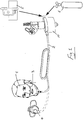
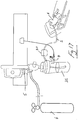
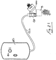
- FIG. 1 there is illustrated a delivery system according to the invention in which patient 1 undergoing supplemental oxygen therapy is supplied with gas through narrow bore tubing 2 to a nasal cannula 3 or to an oxygen face mask 4.
- the gas may be supplied from a central supply wall connector 5 or from a bottled source 6.
- nasal cannula tubing As the diameter of nasal cannula tubing is generally much smaller than respiratory circuits, (2-5mm ID), it is difficult to transport aerosol along a length of nasal cannula tubing without considerable losses to condensate formed as liquid droplets. These liquid droplets can lead to patient discomfort.
- This invention provides aerosolization into a chamber 10, which sits in the circuit from the supplemental oxygen supply or humidifier, if used, but is separate from the humidifier.
- the supplemental oxygen passes through the chamber 10, in which the aerosol generator 9 is located, and collects the aerosol transporting it to the patient.
- the chamber 10 is designed to selectively allow only smaller aerosol particle sizes (less than 3 microns), suitable for transport along narrow bore tubing, onto to the patient whilst encouraging localised deposition of the aerosol heavier particles.
- Various medicaments available in liquid form may be aerosolised for use in therapies.
- the liquid being aerosolised is water, saline or other solution of water or saline
- the aerosol generator also provides additional humidity to the circuit which may enhance patient comfort where no other humidity source is present.
- Selection of smaller particle sizes may be achieved through use of the following or any combination of the following.
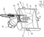
- aerosol from an aerosol generator 9 is delivered into a chamber 10, which sits in the circuit from the supplemental oxygen supply.
- the supplemental oxygen passes through this chamber 10, collects the aerosol and transports it to the patient 1 along the small bone tubing 2.
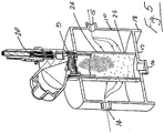
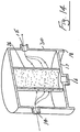
- the aerosol generator 9 is mounted to the housing 10 and delivers aerosol 12 into an oxygen stream 13 flowing between an inlet 14 and an outlet 15 of the housing 10.
- the housing 10 also has a removable plug 16 in the base 17 thereof for draining any liquid that accumulates in the housing 10.
- the housing 10 also has support feet 18 so that the housing can be stood on a suitable surface.
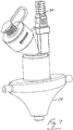
- the aerosol generator 9 in this case has an optional adapter 19 for continuous feed, for example from a drip bag.
- the generator also has a power cable 20 which may connect to an AC/DC adapter or to a control module.
- the inlet 14 and outlet 15 are horizontally opposed.
- a separation plane, provided by a depending skirt 25 positioned between the inlet 14 and outlet 15 acts as a baffle to retard particles above a certain size whilst allowing the smaller particles to pass through for transport along the circuit.
- the majority of particles that exit the housing 10 are less than 3 microns. This is achieved through the combination of impaction on the separation wall 25 and the sharp change in flow direction created by the presence of the wall 25.
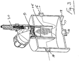
- the separation wall 25 may be extended further towards the floor of the chamber to produce a greater impaction surface and flow disturbance.
- the inlet 14 may be positioned at a substantially lower level (z-direction) relative to the separation plane and the outlet 15 to further adjust the impaction surface and flow disturbance.
- a separation wall 26 extends to and is joined to the floor of the chamber 10 to isolate the aerosol generation space from the airflow space.
- the separation wall in this case is porous, mesh or slotted to retard larger particles and allow smaller particles through to the outlet 15.
- a screen, mesh or slotted plate 27 positioned over the outlet 15 to retard larger particles and allow smaller particles through to the circuit.
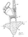
- Figs. 2 to 6 illustrate some features of an aerosol chamber but the design is not limited to this profile. Some or all of the elements may be incorporated into a lower profile design such as the example illustrated in Figs. 7 to 11 in which elements similar to those described above with reference to Figs. 2 to 6 are assigned the same reference numerals. Fig. 9 is not according to the invention.
- the aerosol can be generated in isolation (for example in a t-piece fitting), which sits in the circuit from the supplemental oxygen supply or humidifier, if used, where there is no aerosol particle selection mechanism.
- Various chambers 30 of this type are illustrated in Figs. 12 to 16 .
- the particle separation chamber 30 is located in the circuit between the aerosol generator and the patient as a stand-alone element and receives a mixture of the therapy gas and the full spectrum of generated aerosol particle sizes.
- the chamber 30 selectively allows only smaller aerosol particle sizes, suitable for transport along narrow bore tubing, onto the patient whilst encouraging localised deposition of the aerosol heavier particles.
- the stand-alone chamber 30 may incorporate any combination of the elements described with reference to Figs. 2 to 11 .
- aerosolisation from an aerosol generator 9 may be delivered directly into a bubble humidifier 31 which is supplied with oxygen from an oxygen supply 5 or 6.
- the aerosol is entrained with the humidified oxygen as it exits the bubble humidifier 31, passing into a cannula 3 to the nasal prongs for delivery to a patient 1.
- Aerosolization directly into a chamber suitable for use as a bubble humidifier is also described. This may involve adaptation of existing and commonly available bubble humidifiers to allow addition of the aerosol generator ( Fig. 17 ). This device may be used in combination with an additional downstream baffle box 30 as described with reference to any of Figs. 12 to 16 . Referring to Fig. 18 a bubble humidifier 35 may incorporate any combination of the elements outlined above.
- Vibrating mesh technology which is described in detail below generates an aerosol with a precisely controlled particle size range optimised in general respiratory use for deep lung deposition.
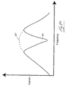
- the distribution of particles can be represented as a normal distribution with the majority of particles produced in the range 2-10 microns.
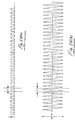
- Test data has shown that the baffle box is effective in removing the larger particles to both lower the effective mean volumetric diameter and also change the distribution of particles to only allow those sizes suitable for transport along narrow bore tubing, onto to the patient with minimal rain-out along the tubing.
- distribution A represents the normal distribution of aerosol particle diameters as produced by an aerosol generator.
- This test was carried out using a commercially available Aerogen SOLO nebuliser product for general respiratory use. Particle sizes fall broadly in the range of 1-10 microns.
- the term "span" is used to describe the spread of the particle size and is defined as (Dv90 - Dv10)/Dv50.
- Dv90 is the volume diameter below which 90% of all particle diameters fall
- Dv10 is the volume diameter below which 10% of all particle diameters fall
- Dv50 volume diameter below which 50% of all particle diameters fall.
- VMD Volumetric Mean Diameter
- Distribution B represents the distribution of aerosol particle diameters produced by the test aerosol generator as measured after exiting the baffle box chamber. This testing was carried out using a commercially available Aerogen SOLO nebuliser product fitted to a chamber configured with lower inlet position, flow diversion and a screen as represented in Figures 4 & 6 . Larger particles are removed from the distribution and only particles suitable for transport along narrow bore tubing are passed through the baffle box. For the specific aerosol generator under test the span was reduced to 0.76 and the VMD was reduced to 3 microns.
- Aerosol is delivered through single narrow bore tubing at flow rates up to 3 1pm, such that rainout is minimized and drug deposition is maximised at the delivery point of a face mask or a nasal cannula.
- the invention has the following advantages:-
- the invention may be used in emergency wards for patients undergoing oxygen treatment via nasal cannula and respite care of same in mechanical ventilation.
- an aerosol generator 9 is used to deliver an aerosolised humidifying agent into the gas.
- the humidifying agent may be sterile water or sterile saline with a salt concentration in the range from 1 micromolar to 154 millimolar. Such saline concentrations can be readily nebulised using the aerosolisation technology used in the invention.
- Any suitable medicament, therapeutic agent, active substance or pharmaceutically active compound than can be nebulised may be employed. It can also act to deliver any agent presented in an aqueous drug solution.
- the system facilitates delivery in aerosol form of, for example, bronchodilators, including ⁇ -agonists, muscarinic antagonists, epinephrine;, surfactants; pain-relief medications including anaesthetics; migraine therapies; anti-infectives; anti-inflammatories, steroids, including corticostroids; chemotherapeutic agents;, mucolytics; vasodilators;,vaccines and hormones.
- bronchodilators including ⁇ -agonists, muscarinic antagonists, epinephrine
- surfactants including anaesthetics
- pain-relief medications including anaesthetics
- migraine therapies anti-infectives
- anti-inflammatories steroids, including corticostroids
- chemotherapeutic agents including mucolytics; vasodilators;,vaccines and hormones.
- the medicament may for example, comprise long-acting beta -adrenoceptor agonists such as salmeterol and formoterol or short-acting beta-adrenoceptor agonists such as albuterol.
- the medicament may be a long-acting muscarinic antagonists such as tiotropium (Spiriva) or short-acting muscarinic antagonists such as ipratropium (Atrovent).
- a long-acting muscarinic antagonists such as tiotropium (Spiriva) or short-acting muscarinic antagonists such as ipratropium (Atrovent).
- Typical anti-infectives include antibiotics such as an aminoglycoside, a tetracycline, a fluroquinolone; anti-microbials such as a cephalosporin; and anti-fungals.
- antibiotics include anti-gram-positive agents such as macrolides, e.g. erythromycin, clarithromycin, azithromycin, and glycopeptides, e.g. vancomycin and teicoplanin, as well as any other anti-gram-positive agent capable of being dissolved or suspended and employed as a suitable aerosol, e.g. oxazoldinone, quinupristin/dalfopristen, etc.
- Antibiotics useful as anti-gram-negative agents may include aminoglycosides, e.g. gentamicin, tobramycin, amikacin, streptomycin, netilmicin, quinolones, e.g. ciprofloxacin, ofloxacin, levofloxacin, tetracyclines, e.g. oxytetracycline, dioxycycline, minocycline, and cotrimoxazole, as well as any other anti-gram-negative agents capable of being dissolved or suspended and employed as a suitable aerosol.
- aminoglycosides e.g. gentamicin, tobramycin, amikacin, streptomycin, netilmicin, quinolones, e.g. ciprofloxacin, ofloxacin, levofloxacin, tetracyclines, e.g. oxytetracycline, dioxycycline, minocycline, and cotrimoxazole
- Anti-inflammatories may be of the steroidal such as budesonide or ciclesonide, non-steroidal, such as sodium cromoglycate or biological type.
- Typical local anaesthetics are, for example, Ropivacaine, Bupivacaine, levobupivacaine, and Lidocaine.
- Chemotherapeutic agents may be alkylating agents, antimetabolites, anthracyclines, plant alkaloids, topoisomerase inhibitors, nitrosoureas, mitotic inhibitors, monoclonal antibodies, tyrosine kinase inhibitors, hormone therapies including corticosteroids, cancer vaccines, antiestrogens, aromatase inhibitors, anti-androgens, anti-angiogenic agents and other anti-tumour agents.
- Surfactant medications are protein-lipid compositions, e.g. phospholipids, that are produced naturally in the body and are essential to the lungs' ability to absorb oxygen. They facilitate respiration by continually modifying surface tension of the fluid normally present within the air sacs, or alveoli, that tube the inside of the lungs. In the absence of sufficient surfactant, these air sacs tend to collapse, and, as a result, the lungs do not absorb sufficient oxygen. Insufficient surfactant in the lungs results in a variety of respiratory illnesses in both animals and humans. Since most of these surfactant medications are animal-based, the current supply is limited, and although synthetic surfactants are available, their manufacture is both inexact and expensive.
- the surfactant medications are typically high in viscosity and are difficult to deliver to the patient's respiratory system.
- the increased efficiency of the pressure-assisted breathing system of the present invention, and the smaller amount of medicament required for a treatment according to the present invention, can be a substantial advantage when such scarce and expensive medicaments are employed.
- the combination of surfactant with other medicaments to improve distribution in the lung and body is also possible.
- Surfactants also possess the capacity to act as anti-adhesion agents.
- an aerosol is delivered into the nasal cannula circuit.
- the distinction between aerosol and vapour is in the size of the particles.
- the majority of aerosol particles that the aerosol generator produces are in the 0.5 to 5.0 micron diameter range.
- Water vapour on the other hand contains individual water molecules which are approximately 0.00001 microns i.e. 10,000 times smaller than the aerosol particles.
- the apparatus comprises a reservoir 100 for storing sterile water or saline solution which may or may not contain a drug, the aerosol generator 9 for aerosolising the solution, and a controller 103 for controlling the operation of the aerosol generator 9.
- This aerosol generator 9 converts the water into an aerosol of a very definable particle size.
- the volumetric median diameter (VMD) would typically be in the range of 2 - 10 microns.
- the controller 103 is used to provide electrical power to drive the aerosol generator 9. This provides the aerosolising action to convey aerosol to the supplemental oxygen being delivered to a patient.
- the nebuliser (or aerosol generator) 9 has a vibratable member which is vibrated at ultrasonic frequencies to produce liquid droplets.
- Some specific, non-limiting examples of technologies for producing fine liquid droplets is by supplying liquid to an aperture plate having a plurality of tapered apertures extending between a first surface and a second surface thereof and vibrating the aperture plate to eject liquid droplets through the apertures.
- Such technologies are described generally in U.S. Pat. Nos. 5,164,740 ; 5,938,117 ; 5,586,550 ; 5,758,637 ; - 6755189 , 6540154 , 6926208 , 7174888 , 6546927 , 6,085,740 , and US2005/021766A .
- the present invention is not limited for use only with such devices.
- the liquid to be aerosolised is received at the first surface, and the aerosol generator 9 generates the aerosolised liquid at the second surface by ejecting droplets of the liquid upon vibration of the vibratable member.
- the apertures in the vibratable member are sized to aerosolise the liquid by ejecting droplets of the liquid such that the majority of the droplets by mass have a size of less than 5 micrometers.
- the aerosol generator 9 comprises a vibratable member 140, a piezoelectric element 141 and a washer 142, which are sealed within a silicone overmould 143 and secured in place within a housing 136 using a retaining ring 144.
- the vibratable member 140 has a plurality of tapered apertures extending between a first surface and a second surface thereof.
- the first surface of the vibratable member 140 which in use faces upwardly, receives the liquid from the reservoir 101 and the aerosolised liquid, is generated at the second surface of the vibratable member 140 by ejecting droplets of liquid upon vibration of the member 140. In use the second surface faces downwardly.
- the apertures in the vibratable member 140 may be sized to produce an aerosol in which the majority of the droplets by weight have a size of less than 5 micrometers.
- the vibratable member 140 could be non-planar, and may be dome-shaped in geometry.
- the complete nebuliser may be supplied in sterile form, which is a significant advantage.
- the aerosol generator unit may comprise a collar or neck 136 to facilitate mounting of the unit, for example to the housings.
- the interfitting may be a push fit. This enables the unit to be easily mounted and de-mounted, for example for cleaning.
- the neck or collar 136 at least partially lines the opening into the housing and may project inwardly to define an internal wall as described above.
- the controller 103 controls operation of and provides a power supply to the aerosol generator 9.
- the aerosol generator 9 has a housing which defines the reservoir 101.
- the housing has a signal interface port 138 fixed to the lower portion of the reservoir 101 to receive a control signal from the controller 103.
- the controller 103 may be connected to the signal interface port 138 by means of a control lead 139 which has a docking member 150 for mating with the port 138.
- a control signal and power may be passed from the controller 103 through the lead 139 and the port 138 to the aerosol generator 9 to control the operation of the aerosol generator 9 and to supply power to the aerosol generator 9 respectively.
- the power source for the controller 103 may be an on-board power source, such as a rechargeable battery, or a remote power source, such as a mains power source, or an insufflator power source.
- a remote power source such as a mains power source, or an insufflator power source.
- an AC-DC converter may be connected between the AC power source and the controller 103.
- a power connection lead may be provided to connect a power socket of the controller 103 with the remote power source.
- the controller 103 has a housing and a user interface to selectively control operation of the aerosol generator 9.
- the user interface is provided on the housing which, in use, is located remote from the aerosol generator housing.
- the user interface may be in the form of, for example, an on-off button.
- a button can be used to select pre-set values for simplicity of use.
- a dial mechanism can be used to select from a range of values from 0-100%. This embodiment has the advantage of providing the aerosol at a much lower flow rate which will 'rain out' less and alleviate the need for the baffle box system.
- Status indication means are also provided on the housing to indicate the operational state of the aerosol generator 9.
- the status indication means may be in the form of two visible LED's, with one LED being used to indicate power and the other LED being used to indicate aerosol delivery.
- one LED may be used to indicate an operational state of the aerosol generator 9, and the other LED may be used to indicate a rest state of the aerosol generator 9.
- a fault indicator may also be provided in the form of an LED on the housing.
- a battery charge indicator in the form of an LED may be provided at the side of the housing.
- the liquid in the reservoir 101 flows by gravitational action towards the aerosol generator 9 at the lower medicament outlet.
- the controller 103 may then be activated to supply power and a control signal to the aerosol generator 9, which causes the piezoelectric element 141 to vibrate the non-planar member 140.
- This vibration of the non-planar member 140 causes the aqueous solution at the top surface of the member 140 to pass through the apertures to the lower surface where the aqueous solution is aerosolised by the ejection of small droplets of solution.
- a flow rate sensor/meter may be used to determine the flow rate of the ventilation gas.
- the controller 103 commences operation of the aerosol generator 9 to aerosolise the aqueous solution.
- the aerosolised aqueous solution is entrained with the ventilation gas, and delivered to the patient.
- the flow rate sensor/meter determines the alteration, and the controller 103 alters the pulse rate of the vibratable member of the nebuliser accordingly.
- the controller 103 is in communication with the flow rate sensor/meter.
- the controller 103 is configured to control operation of the aerosol generator 9, responsive to the fluid flow rate of the ventilation gas and also independent of the fluid flow rate of the ventilation gas as required.
- the controller 103 is configured to control operation of the aerosol generator 9 by controlling the pulse rate at a set frequency of vibration of the vibratable member, and thus controlling the fluid flow rate of the aqueous solutions. This has the advantage of reducing 'rain out' such as by way of reduced aerosol velocity.
- the controller 103 may comprise a microprocessor 104, a boost circuit 105, and a drive circuit 106.
- Fig. 20 illustrates the microprocessor 104, the boost circuit 105, the drive circuit 106 comprising impedance matching components (inductor), the nebuliser 9, and the aerosol.
- the inductor impedance is matched to the impedance of the piezoelectric element of the aerosol generator 9.
- the microprocessor 104 generates a square waveform of 128KHz which is sent to the drive circuit 106.
- the boost circuit 105 generates a 12V DC voltage required by the drive circuit 106 from an input of either a 4.5V battery or a 9V AC/DC adapter.
- the circuit is matched to the impedance of the piezo ceramic element to ensure enhanced energy transfer.
- a drive frequency of 128 KHz is generated to drive the nebuliser at close to its resonant frequency so that enough amplitude is generated to break off droplets and produce the aerosol. If this frequency is chopped at a lower frequency such that aerosol is generated for a short time and then stopped for a short time this gives good control of the nebuliser's flow rate. This lower frequency is called the pulse rate.
- the drive frequency may be started and stopped as required using the microprocessor 104. This allows for control of flow rate by driving the nebuliser 9 for any required pulse rate.
- the microprocessor 104 may control the on and off times to an accuracy of milliseconds.
- the nebuliser 9 may be calibrated at a certain pulse rate by measuring how long it takes to deliver a know quantity of solution. There is a linear relationship between the pulse rate and the nebuliser flow rate. This may allow for accurate control over the delivery rate of the aqueous solution.
- the nebuliser drive circuit consists of the electronic components designed to generate output sine waveform of approximately 100V AC which is fed to nebuliser 9 causing aerosol to be generated.
- the nebuliser drive circuit 106 uses inputs from microprocessor 104 and boost circuit 105 to achieve its output.
- the circuit is matched to the impedance of the piezo ceramic element to ensure good energy transfer.
- the aerosol generator 9 may be configured to operate in a variety of different modes, such as continuous, and/or phasic, and/or optimised.
- the pulse control is particularly relevant in the case where the aerosol generator itself provides a humidifier.
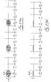
- Fig 25(a) illustrates a 5V DC square waveform output from the microprocessor 104 to the drive circuit 106.
- Fig 25(b) shows a low power, ⁇ 100V AC sine waveform output from drive circuit 106 to nebuliser 9. Both waveforms have a period p of 7.8 ⁇ S giving them a frequency of 1/7.8 ⁇ s which is approximately 128KHz. Both waveforms are continuous without any pulsing.
- the aerosol generator may be operated in this mode to achieve 100% aerosol output.
- Figs 26(a) in another example, there is illustrated a 5V DC square waveform output from the microprocessor 104 to the drive circuit 106.
- Fig 26(b) shows a low power, ⁇ 100V AC sine waveform output from the drive circuit 106 to the nebuliser 9. Both waveforms have a period p of 7.8 ⁇ S giving them a frequency of 1/7.8 ⁇ s which is approximately 128KHz. In both cases the waveforms are chopped (stopped/OFF) for a period of time x. In this case the off time x is equal to the on time x.
- the aerosol generator may be operated in this mode to achieve 50% aerosol output.
- Figs 27(a) there is illustrated a 5V DC square waveform output from microprocessor 104 to drive circuit 106.
- Fig 27(b) shows a low power, ⁇ 100V AC sine waveform output from the drive circuit 106 to the nebuliser 9. Both waveforms have a period p of 7.8 ⁇ S giving them a frequency of 1/7.8 ⁇ s which is approximately 128KHz.
- the wavefoms are chopped (stopped/OFF) for a period of time x. In this case the off time is 3x while the on time is x.
- the aerosol generator may be operated in this mode to achieve 25% aerosol output.
- pulsing is achieved by specifying an on-time and off-time for the vibration of the aperture plate. If the on-time is set to 200 vibrations and off-time is set to 200 vibrations, the pulse rate is 50% (1 ⁇ 2 on 1 ⁇ 2 off). This means that the flow rate is half of that of a fully driven aperture plate. Any number of vibrations can be specified but to achieve a linear relationship between flow rate and pulse rate a minimum number of on-time vibrations is specified since it takes a finite amount of time for the aperture plate to reach its maximum amplitude of vibrations.
- the drive frequency can be started and stopped as required by the microprocessor; this allows control of flow rate by driving the nebuliser for any required pulse rate.
- the microprocessor can control the on and off times with an accuracy of microseconds.
- a nebuliser can be calibrated at a certain pulse rate by measuring how long it takes to deliver a known quantity of solution. There is a linear relationship between the pulse rate and that nebuliser's flow rate. This allows accurate control of the rate of delivery of the aerosolised aqueous solution.
- the pulse rate may be lowered so that the velocity of the emerging aerosol is much reduced so that impaction rain-out is reduced.
- Another embodiment may have a reduced hole size on the aperture plate which will generate an aerosol with a reduced particle size ( ⁇ 3 um) and at a slower flow rate to provide less 'rain out' in the tubing system.
- Detection of when the aperture plate is dry can be achieved by using the fact that a dry aperture plate has a well defined resonant frequency. If the drive frequency is swept from 120kHz to 145kHz and the current is measured then if a minimum current is detected less than a set value, the aperture plate must have gone dry. A wet aperture plate has diminished or no resonant frequency.
- the apparatus of the invention may be configured to determine whether there is any of the first fluid in contact with the aerosol generator 9. By determining an electrical characteristic of the aerosol generator 9, for example the current flowing through the aerosol generator 9, over a range of vibration frequencies, and comparing this electrical characteristic against a pre-defined set of data, it is possible to determine whether the aerosol generator 9 has any solution in contact with the aerosol generator 9.
- Fig. 29 illustrates a curve 80 of frequency versus current when there is some of the solution in contact with the aerosol generator 9, and illustrates a curve 90 of frequency versus current when there is none of the solution in contact with the aerosol generator 2.
- Fig. 29 illustrates the wet aperture plate curve 80 and the dry aperture plate curve 90.
- a pump can be added in line to give fine control of the liquid delivery rate which can be nebulised drip by drip.
- the rate would be set so that liquid would not build up in the nebuliser. This system is particularly suitable for constant low dose delivery.
Landscapes
- Health & Medical Sciences (AREA)
- Engineering & Computer Science (AREA)
- Life Sciences & Earth Sciences (AREA)
- Public Health (AREA)
- Anesthesiology (AREA)
- Biomedical Technology (AREA)
- Heart & Thoracic Surgery (AREA)
- Hematology (AREA)
- Veterinary Medicine (AREA)
- Animal Behavior & Ethology (AREA)
- General Health & Medical Sciences (AREA)
- Pulmonology (AREA)
- Emergency Medicine (AREA)
- Otolaryngology (AREA)
- Chemical & Material Sciences (AREA)
- Dispersion Chemistry (AREA)
- Bioinformatics & Cheminformatics (AREA)
- Medicinal Preparation (AREA)
- Respiratory Apparatuses And Protective Means (AREA)
Priority Applications (1)
| Application Number | Priority Date | Filing Date | Title |
|---|---|---|---|
| PL09787421T PL2337600T3 (pl) | 2008-09-26 | 2009-09-28 | System podawania tlenu uzupełniającego |
Applications Claiming Priority (2)
| Application Number | Priority Date | Filing Date | Title |
|---|---|---|---|
| US10049108P | 2008-09-26 | 2008-09-26 | |
| PCT/IE2009/000067 WO2010035251A2 (en) | 2008-09-26 | 2009-09-28 | A supplemental oxygen delivery system |
Publications (2)
| Publication Number | Publication Date |
|---|---|
| EP2337600A2 EP2337600A2 (en) | 2011-06-29 |
| EP2337600B1 true EP2337600B1 (en) | 2019-09-18 |
Family
ID=41402200
Family Applications (1)
| Application Number | Title | Priority Date | Filing Date |
|---|---|---|---|
| EP09787421.8A Active EP2337600B1 (en) | 2008-09-26 | 2009-09-28 | Supplemental oxygen delivery system |
Country Status (5)
| Country | Link |
|---|---|
| US (5) | US8418690B2 (enExample) |
| EP (1) | EP2337600B1 (enExample) |
| JP (1) | JP2012503518A (enExample) |
| PL (1) | PL2337600T3 (enExample) |
| WO (1) | WO2010035251A2 (enExample) |
Cited By (1)
| Publication number | Priority date | Publication date | Assignee | Title |
|---|---|---|---|---|
| EP4051351A1 (en) * | 2019-10-31 | 2022-09-07 | ResMed Sensor Technologies Limited | Systems and methods for injecting substances into a respiratory system |
Families Citing this family (80)
| Publication number | Priority date | Publication date | Assignee | Title |
|---|---|---|---|---|
| US8551534B2 (en) | 2007-10-10 | 2013-10-08 | Parion Sciences, Inc. | Inhaled hypertonic saline delivered by a heated nasal cannula |
| US8418690B2 (en) | 2008-09-26 | 2013-04-16 | Stamford Devices Limited | Supplemental oxygen delivery system |
| MX339742B (es) | 2010-05-18 | 2016-06-07 | Teva Pharma Ireland | Contadores de dosis para inhaladores, inhaladores y flechas de los mismos. |
| US8915245B2 (en) * | 2010-10-07 | 2014-12-23 | Vapotherm, Inc. | Nebulizer systems, apparatus and methods for respiratory therapy |
| RU2594241C2 (ru) | 2010-12-17 | 2016-08-10 | Конинклейке Филипс Электроникс Н.В. | Увлажнительная система для увлажнения газа, доставляемого пациенту |
| WO2012152321A1 (en) * | 2011-05-10 | 2012-11-15 | Fraunhofer-Gesellschaft zur Förderung der angewandten Forschung e.V. | Controllable fluid sample dispenser and methods using the same |
| WO2012152319A2 (en) * | 2011-05-10 | 2012-11-15 | Fraunhofer-Gesellschaft zur Förderung der angewandten Forschung e.V. | Controllable scent sample dispenser, and animal training and testing system for detecting scents |
| US8778383B2 (en) | 2011-06-07 | 2014-07-15 | Parion Sciences, Inc. | Methods of treatment |
| US8945605B2 (en) | 2011-06-07 | 2015-02-03 | Parion Sciences, Inc. | Aerosol delivery systems, compositions and methods |
| CN103191500B (zh) * | 2012-01-06 | 2016-02-24 | 北京万生人和科技有限公司 | 一种氧气罐 |
| EP3216475B1 (en) * | 2012-01-24 | 2020-07-22 | Vapotherm, Inc. | Systems for providing respiratory therapy |
| GB2541301B (en) | 2012-03-15 | 2017-07-12 | Fisher & Paykel Healthcare Ltd | Respiratory gas humidification system |
| GB2577634B (en) | 2012-04-27 | 2020-09-30 | Fisher & Paykel Healthcare Ltd | Respiratory humidification apparatus |
| US9478473B2 (en) * | 2013-05-21 | 2016-10-25 | Globalfoundries Inc. | Fabricating a microelectronics lid using sol-gel processing |
| ES1094181Y (es) * | 2013-05-23 | 2014-02-17 | Alarcon Andres Tendero | Dispositivo de administracion continua de nebulización |
| CN103800979B (zh) | 2013-06-19 | 2018-05-04 | 林信涌 | 保健气体产生器 |
| CN203291354U (zh) * | 2013-06-19 | 2013-11-20 | 林信涌 | 防爆式保健气体产生器 |
| CN105592935B (zh) | 2013-07-24 | 2018-10-16 | 斯坦福设备有限公司 | 喷雾器振动孔板驱动频率控制及监测 |
| EP3488889A1 (en) | 2013-08-08 | 2019-05-29 | Vapotherm, Inc. | Respiratory therapy condensation adaptor |
| GB2583046B8 (en) | 2013-09-13 | 2021-04-28 | Fisher & Paykel Healthcare Ltd | Resilient probe mount for a humidification system |
| US10449319B2 (en) | 2014-02-07 | 2019-10-22 | Fisher & Paykel Healthcare Limited | Respiratory humidification system |
| AU2015226287B2 (en) | 2014-03-05 | 2019-01-31 | Fraunhofer-Gesellschaft zur Förderung der angewandten Forschung e.V. | Humidifier for humidifying an aerosol |
| FR3018463B1 (fr) * | 2014-03-13 | 2019-04-19 | Vdlv | Appareil pour gouter des e-liquides a inhaler en cigarette electronique (fragrances et saveurs) |
| GB201408561D0 (en) * | 2014-05-14 | 2014-06-25 | The Technology Partnership Plc | Aerosolisation engine for liquid drug delivery |
| EP3607988B1 (en) | 2014-06-03 | 2025-09-10 | Fisher & Paykel Healthcare Limited | A humidification chamber for a respiratory therapy apparatus |
| EP3412327A1 (en) * | 2014-06-06 | 2018-12-12 | Vapotherm, Inc. | Heated nebulizer adapter for respiratory therapy |
| NZ732004A (en) | 2014-06-19 | 2018-11-30 | ResMed Pty Ltd | Patient interface for respiratory therapy |
| US10857313B2 (en) * | 2014-07-01 | 2020-12-08 | Aerami Therapeutics, Inc. | Liquid nebulization systems and methods |
| CA3195740A1 (en) * | 2014-11-25 | 2016-06-02 | Fisher & Paykel Healthcare Limited | Substance delivery arrangement for gas therapy device |
| US9907487B2 (en) * | 2015-01-22 | 2018-03-06 | Alexander Gelfand | Non-invasive method and apparatus for determining lung tissue thermal properties and for extra vascular lung water measurement |
| US10369317B2 (en) | 2015-05-18 | 2019-08-06 | Scott Schaffer | Clip-on nasal air humidifying and epistaxis-prevention device and methods for use with supplemental oxygen |
| IN2015CH02887A (enExample) * | 2015-06-09 | 2015-07-10 | Venkatanarayana Nibhanipudi Kumara | |
| GB201510166D0 (en) * | 2015-06-11 | 2015-07-29 | The Technology Partnership Plc | Spray delivery device |
| US11058842B2 (en) * | 2015-08-23 | 2021-07-13 | Pivotal Biotech LLC | Adapter with moisture trap assembly for respiratory circuit |
| CN105749393B (zh) * | 2016-02-02 | 2018-05-29 | 青岛大学附属医院 | 一种雾化吸入系统 |
| WO2017192774A1 (en) | 2016-05-03 | 2017-11-09 | Pneuma Respiratory, Inc. | Methods for the systemic delivery of therapeutic agents to the pulmonary system using a droplet delivery device |
| WO2017192773A1 (en) | 2016-05-03 | 2017-11-09 | Pneuma Respiratory, Inc. | Methods for treatment of pulmonary lung diseases with improved therapeutic efficacy and improved dose efficiency |
| EP3452152B1 (en) | 2016-05-03 | 2025-07-02 | Pneuma Respiratory, Inc. | A droplet delivery device for generating and delivering droplets to the pulmonary system |
| WO2017192782A1 (en) | 2016-05-03 | 2017-11-09 | Pneuma Respiratory, Inc. | Systems and methods comprising a droplet delivery device and a breathing assist device for therapeutic treatment |
| EP3452150B1 (en) | 2016-05-03 | 2024-01-17 | Pneuma Respiratory, Inc. | Droplet delivery device for delivery of fluids to the pulmonary system |
| SG10202106016TA (en) | 2016-12-07 | 2021-07-29 | Fisher and paykel healthcare ltd | Sensing arrangements for medical devices |
| AU2018240521B2 (en) * | 2017-03-23 | 2023-06-01 | Stamford Devices Ltd | Retrofit aerosol delivery system and method |
| EP4223335A3 (en) | 2017-05-19 | 2023-11-08 | Pneuma Respiratory, Inc. | Dry powder delivery device and methods of use |
| EP3672734B1 (en) | 2017-08-25 | 2021-09-22 | Stamford Devices Limited | Protection of aperture plate during aerosol generation |
| JP2020536614A (ja) | 2017-10-04 | 2020-12-17 | ニューマ・リスパイラトリー・インコーポレイテッド | 呼吸により電気的に作動するインライン液滴送達装置および使用方法 |
| CA3079189A1 (en) | 2017-10-17 | 2019-04-25 | Pneuma Respiratory, Inc. | Nasal drug delivery apparatus and methods of use |
| WO2019083557A1 (en) * | 2017-10-28 | 2019-05-02 | Vuber Technologies, Llc | SYSTEM AND METHOD FOR DELIVERY OF NEBULIZED CANNABINOID |
| JP2021502178A (ja) | 2017-11-08 | 2021-01-28 | ニューマ・リスパイラトリー・インコーポレイテッド | 小容積アンプルを有して呼吸により電気的に作動するインライン液滴送達装置および使用方法 |
| TWI645869B (zh) * | 2017-11-15 | 2019-01-01 | 貝斯美德股份有限公司 | 具有內部隔牆的加濕室 |
| EP3700492B1 (en) | 2017-12-03 | 2021-09-08 | West Pharma. Services IL, Ltd. | Liquid transfer device with telescopic vial adapter for use with infusion liquid container and discrete injection vial |
| WO2019115771A1 (en) * | 2017-12-15 | 2019-06-20 | Pari Pharma Gmbh | Nebuliser system, holding system, combination comprising nebuliser system and holding system, and aerosol administration method |
| USD912247S1 (en) * | 2018-05-17 | 2021-03-02 | Dwk Life Sciences Gmbh | Connection cap device |
| CN112368040A (zh) | 2018-05-31 | 2021-02-12 | 蒸汽热能公司 | 近机器侧雾化器 |
| US12102755B2 (en) | 2018-05-31 | 2024-10-01 | Vapotherm, Inc. | Cannula-based vibrating mesh nebulizer |
| USD903864S1 (en) * | 2018-06-20 | 2020-12-01 | West Pharma. Services IL, Ltd. | Medication mixing apparatus |
| US20200016360A1 (en) | 2018-07-11 | 2020-01-16 | Martin Allan Morris | Low flow adaptor to deliver aerosols via nasal cannula without crashout |
| US12501929B2 (en) | 2018-08-22 | 2025-12-23 | Qnovia, Inc. | Electronic device for producing an aerosol for inhalation by a person |
| WO2020041641A1 (en) | 2018-08-22 | 2020-02-27 | Respira Technologies, Inc. | Electronic device for producing an aerosol for inhalation by a person |
| WO2020120212A1 (en) * | 2018-12-11 | 2020-06-18 | Koninklijke Philips N.V. | Humidification and mucus mobilization with an on-demand humidifier |
| USD923812S1 (en) | 2019-01-16 | 2021-06-29 | West Pharma. Services IL, Ltd. | Medication mixing apparatus |
| JP1648075S (enExample) | 2019-01-17 | 2019-12-16 | ||
| WO2020148748A1 (en) | 2019-01-18 | 2020-07-23 | West Pharma. Services IL, Ltd. | Liquid transfer devices for use with intravenous (iv) bottles |
| US11918542B2 (en) | 2019-01-31 | 2024-03-05 | West Pharma. Services IL, Ltd. | Liquid transfer device |
| CN109771784B (zh) * | 2019-03-20 | 2021-07-06 | 西安交通大学医学院第一附属医院 | 一种呼吸内科用氧气机吸氧罩 |
| CN113677382B (zh) | 2019-04-09 | 2023-06-09 | 西医药服务以色列有限公司 | 具有集成式注射器的液体输送装置 |
| CN118697642A (zh) | 2019-04-30 | 2024-09-27 | 西部制药服务有限公司(以色列) | 液体输送装置以及药用瓶子重构和分配设备 |
| EP4007627B1 (en) | 2019-08-02 | 2024-02-14 | Stamford Devices Limited | Nebulizer comprising a manually adjustable user interface |
| US11878115B2 (en) | 2019-09-26 | 2024-01-23 | Vapotherm, Inc. | Internal cannula mounted nebulizer |
| US20210113783A1 (en) | 2019-10-20 | 2021-04-22 | Respira Technologies, Inc. | Electronic devices and liquids for aerosolizing and inhaling therewith |
| US20210346613A1 (en) * | 2020-05-05 | 2021-11-11 | Mahesh Kumar KHAITAN | Controlled delivery device for treating coronavirus infections and methods thereof |
| USD956958S1 (en) | 2020-07-13 | 2022-07-05 | West Pharma. Services IL, Ltd. | Liquid transfer device |
| WO2022013088A1 (en) * | 2020-07-14 | 2022-01-20 | Stamford Devices Limited | A vaccine administration apparatus and method |
| EP4208237B1 (en) * | 2020-09-01 | 2024-11-06 | Stamford Devices Limited | Aerosol high flow therapy apparatus |
| US12471625B2 (en) | 2020-11-01 | 2025-11-18 | Qnovia, Inc. | Electronic devices and liquids for aerosolizing and inhaling therewith |
| WO2022140675A1 (en) * | 2020-12-23 | 2022-06-30 | Vapotherm, Inc. | High flow aerosol blending |
| PL4359046T3 (pl) | 2021-06-22 | 2025-10-13 | Pneuma Respiratory, Inc. | Urządzenie do podawania kropelkowego z wyrzutem wypychającym |
| US12279650B2 (en) | 2022-04-22 | 2025-04-22 | Qnovia, Inc. | Electronic devices for aerosolizing and inhaling liquid having an enclosed interior air passageway with diaphragm and pressure sensor |
| US12161795B2 (en) | 2022-07-18 | 2024-12-10 | Pneuma Respiratory, Inc. | Small step size and high resolution aerosol generation system and method |
| WO2026009166A1 (en) * | 2024-07-03 | 2026-01-08 | Kaer Biotherapeutics Corporation | Ergonomic and utilitarian aerosol delivery system |
| WO2026011218A1 (en) * | 2024-07-12 | 2026-01-15 | ResMed Pty Ltd | Humidifiers |
Citations (1)
| Publication number | Priority date | Publication date | Assignee | Title |
|---|---|---|---|---|
| US5355872A (en) * | 1992-03-04 | 1994-10-18 | Riggs John H | Low flow rate nebulizer apparatus and method of nebulization |
Family Cites Families (30)
| Publication number | Priority date | Publication date | Assignee | Title |
|---|---|---|---|---|
| US3404843A (en) | 1967-01-23 | 1968-10-08 | G S Internat Lab Corp | Aerosol apparatus for inhalation therapy |
| JPS508093B1 (enExample) | 1970-12-28 | 1975-04-02 | ||
| US3968812A (en) * | 1971-10-12 | 1976-07-13 | Instrumentation Industries, Inc. | Apparatus for removal of condensed moisture from respiratory tubes |
| JPS61238247A (ja) * | 1985-04-15 | 1986-10-23 | キヤデイマ メデイカル プロダクツ インコ−ポレ−テツド | 放射性エ−ロゾル吸入装置 |
| US4805609A (en) * | 1987-07-17 | 1989-02-21 | Josephine A. Roberts | Pressurized ventilation system for patients |
| US5938117A (en) | 1991-04-24 | 1999-08-17 | Aerogen, Inc. | Methods and apparatus for dispensing liquids as an atomized spray |
| US5164740A (en) | 1991-04-24 | 1992-11-17 | Yehuda Ivri | High frequency printing mechanism |
| US6540154B1 (en) | 1991-04-24 | 2003-04-01 | Aerogen, Inc. | Systems and methods for controlling fluid feed to an aerosol generator |
| US6629646B1 (en) | 1991-04-24 | 2003-10-07 | Aerogen, Inc. | Droplet ejector with oscillating tapered aperture |
| US5186166A (en) * | 1992-03-04 | 1993-02-16 | Riggs John H | Powder nebulizer apparatus and method of nebulization |
| US5586550A (en) | 1995-08-31 | 1996-12-24 | Fluid Propulsion Technologies, Inc. | Apparatus and methods for the delivery of therapeutic liquids to the respiratory system |
| US6205999B1 (en) | 1995-04-05 | 2001-03-27 | Aerogen, Inc. | Methods and apparatus for storing chemical compounds in a portable inhaler |
| US5758637A (en) | 1995-08-31 | 1998-06-02 | Aerogen, Inc. | Liquid dispensing apparatus and methods |
| US6085740A (en) | 1996-02-21 | 2000-07-11 | Aerogen, Inc. | Liquid dispensing apparatus and methods |
| JPH11512299A (ja) * | 1995-09-06 | 1999-10-26 | ライダー,スチーブン,エル. | 可変酸素濃度高流量噴霧器 |
| US6044841A (en) * | 1997-08-29 | 2000-04-04 | 1263152 Ontario Inc. | Breath actuated nebulizer with valve assembly having a relief piston |
| US6202991B1 (en) * | 1999-02-03 | 2001-03-20 | Nicholas Edward Coniglio | Bubble humidifier with valve inlet for supplying liquid therein |
| WO2001038002A1 (en) * | 1999-09-13 | 2001-05-31 | Sheffield Pharmaceuticals, Inc. | Aerosol airflow control system and method |
| AU2001235009B2 (en) * | 2000-02-11 | 2004-10-07 | Respironics Respiratory Drug Delivery (Uk) Ltd | Drug delivery apparatus |
| US7971588B2 (en) * | 2000-05-05 | 2011-07-05 | Novartis Ag | Methods and systems for operating an aerosol generator |
| US7600511B2 (en) * | 2001-11-01 | 2009-10-13 | Novartis Pharma Ag | Apparatus and methods for delivery of medicament to a respiratory system |
| US8336545B2 (en) * | 2000-05-05 | 2012-12-25 | Novartis Pharma Ag | Methods and systems for operating an aerosol generator |
| US6546927B2 (en) | 2001-03-13 | 2003-04-15 | Aerogen, Inc. | Methods and apparatus for controlling piezoelectric vibration |
| US8616195B2 (en) * | 2003-07-18 | 2013-12-31 | Novartis Ag | Nebuliser for the production of aerosolized medication |
| WO2005115520A1 (en) * | 2004-05-20 | 2005-12-08 | Discovery Laboratories, Inc. | Methods , systems and devices for noninvasive pulmonary delivery |
| US7926484B2 (en) | 2005-05-03 | 2011-04-19 | Aeon Research And Technology, Inc. | Interface accessory for use with an aerosol inhalation system |
| WO2007041156A2 (en) * | 2005-09-29 | 2007-04-12 | Nektar Therapeutics | Antibiotic formulations, unit doses, kits, and methods |
| US20080078385A1 (en) * | 2006-09-29 | 2008-04-03 | Yang Xiao | System and method for delivery of medication via inhalation |
| US8418690B2 (en) * | 2008-09-26 | 2013-04-16 | Stamford Devices Limited | Supplemental oxygen delivery system |
| WO2011057235A2 (en) * | 2009-11-09 | 2011-05-12 | Virginia Commonwealth University | Improved delivery of submicrometer and nonometer aerosols to the lungs using hygroscopic excipients or dual stream nasal delivery |
-
2009
- 2009-09-28 US US12/568,399 patent/US8418690B2/en active Active
- 2009-09-28 JP JP2011528492A patent/JP2012503518A/ja active Pending
- 2009-09-28 WO PCT/IE2009/000067 patent/WO2010035251A2/en not_active Ceased
- 2009-09-28 EP EP09787421.8A patent/EP2337600B1/en active Active
- 2009-09-28 PL PL09787421T patent/PL2337600T3/pl unknown
-
2013
- 2013-03-14 US US13/829,044 patent/US9572950B2/en active Active
-
2017
- 2017-01-04 US US15/398,059 patent/US10792455B2/en active Active
-
2020
- 2020-01-22 US US16/749,024 patent/US11672939B2/en active Active
- 2020-09-09 US US17/015,179 patent/US11806478B2/en active Active
Patent Citations (2)
| Publication number | Priority date | Publication date | Assignee | Title |
|---|---|---|---|---|
| US5355872A (en) * | 1992-03-04 | 1994-10-18 | Riggs John H | Low flow rate nebulizer apparatus and method of nebulization |
| US5355872B1 (en) * | 1992-03-04 | 1998-10-20 | John H Riggs | Low flow rate nebulizer apparatus and method of nebulization |
Cited By (1)
| Publication number | Priority date | Publication date | Assignee | Title |
|---|---|---|---|---|
| EP4051351A1 (en) * | 2019-10-31 | 2022-09-07 | ResMed Sensor Technologies Limited | Systems and methods for injecting substances into a respiratory system |
Also Published As
| Publication number | Publication date |
|---|---|
| US20200155786A1 (en) | 2020-05-21 |
| EP2337600A2 (en) | 2011-06-29 |
| US8418690B2 (en) | 2013-04-16 |
| WO2010035251A3 (en) | 2010-05-20 |
| US20200405995A1 (en) | 2020-12-31 |
| US11672939B2 (en) | 2023-06-13 |
| US20130199529A1 (en) | 2013-08-08 |
| US20100089395A1 (en) | 2010-04-15 |
| US11806478B2 (en) | 2023-11-07 |
| US9572950B2 (en) | 2017-02-21 |
| JP2012503518A (ja) | 2012-02-09 |
| WO2010035251A2 (en) | 2010-04-01 |
| US20170182279A1 (en) | 2017-06-29 |
| US10792455B2 (en) | 2020-10-06 |
| PL2337600T3 (pl) | 2020-04-30 |
Similar Documents
| Publication | Publication Date | Title |
|---|---|---|
| US11806478B2 (en) | Supplemental oxygen delivery system | |
| US20120234321A1 (en) | Aerosolisation system | |
| EP3254632B1 (en) | Humidification in breathing circuits | |
| JP6174056B2 (ja) | 吸入用装置及び吸入用装置のための混合流路 | |
| CN101247898B (zh) | 超音波气雾产生器 | |
| US20120192863A1 (en) | Humidification in breathing circuits | |
| US20090241948A1 (en) | Humidification in breathing circuits | |
| US20110230820A1 (en) | Insufflation of body cavities | |
| US10471227B1 (en) | Low flow adaptor to deliver aerosols via nasal cannula without crashout | |
| US11298472B2 (en) | Ultrasonic nebulizer | |
| CN112469459B (zh) | 用于液体物质的分子汽化的系统 | |
| EP2274034A1 (en) | Insufflation of body cavities | |
| EP2371409A1 (en) | Insufflation of body cavities | |
| IE20090749A1 (en) | A supplemental oxygen delivery system | |
| IE20080243A1 (en) | Humidifaction in breathing | |
| HK1121424B (en) | Ultrasonic aerosol generator |
Legal Events
| Date | Code | Title | Description |
|---|---|---|---|
| PUAI | Public reference made under article 153(3) epc to a published international application that has entered the european phase |
Free format text: ORIGINAL CODE: 0009012 |
|
| 17P | Request for examination filed |
Effective date: 20110426 |
|
| AK | Designated contracting states |
Kind code of ref document: A2 Designated state(s): AT BE BG CH CY CZ DE DK EE ES FI FR GB GR HR HU IE IS IT LI LT LU LV MC MK MT NL NO PL PT RO SE SI SK SM TR |
|
| AX | Request for extension of the european patent |
Extension state: AL BA RS |
|
| DAX | Request for extension of the european patent (deleted) | ||
| STAA | Information on the status of an ep patent application or granted ep patent |
Free format text: STATUS: EXAMINATION IS IN PROGRESS |
|
| 17Q | First examination report despatched |
Effective date: 20180320 |
|
| GRAP | Despatch of communication of intention to grant a patent |
Free format text: ORIGINAL CODE: EPIDOSNIGR1 |
|
| STAA | Information on the status of an ep patent application or granted ep patent |
Free format text: STATUS: GRANT OF PATENT IS INTENDED |
|
| RIC1 | Information provided on ipc code assigned before grant |
Ipc: B05B 17/06 20060101ALN20190521BHEP Ipc: A61M 16/14 20060101ALI20190521BHEP Ipc: A61M 11/00 20060101ALI20190521BHEP Ipc: B05B 12/08 20060101ALN20190521BHEP Ipc: A61M 16/08 20060101ALI20190521BHEP Ipc: A61M 16/06 20060101ALI20190521BHEP Ipc: A61M 16/00 20060101ALI20190521BHEP Ipc: A61M 16/16 20060101ALI20190521BHEP Ipc: A61M 15/00 20060101AFI20190521BHEP Ipc: B05B 17/00 20060101ALN20190521BHEP |
|
| INTG | Intention to grant announced |
Effective date: 20190624 |
|
| RIN1 | Information on inventor provided before grant (corrected) |
Inventor name: DUFFY, CONOR Inventor name: POWER, JOHN, SYLVESTER Inventor name: FINK, JAMES, B. Inventor name: FAHY, TREVOR, STEPHEN |
|
| GRAS | Grant fee paid |
Free format text: ORIGINAL CODE: EPIDOSNIGR3 |
|
| GRAA | (expected) grant |
Free format text: ORIGINAL CODE: 0009210 |
|
| STAA | Information on the status of an ep patent application or granted ep patent |
Free format text: STATUS: THE PATENT HAS BEEN GRANTED |
|
| AK | Designated contracting states |
Kind code of ref document: B1 Designated state(s): AT BE BG CH CY CZ DE DK EE ES FI FR GB GR HR HU IE IS IT LI LT LU LV MC MK MT NL NO PL PT RO SE SI SK SM TR |
|
| REG | Reference to a national code |
Ref country code: GB Ref legal event code: FG4D |
|
| REG | Reference to a national code |
Ref country code: CH Ref legal event code: EP |
|
| REG | Reference to a national code |
Ref country code: NL Ref legal event code: FP |
|
| REG | Reference to a national code |
Ref country code: DE Ref legal event code: R096 Ref document number: 602009059899 Country of ref document: DE |
|
| REG | Reference to a national code |
Ref country code: AT Ref legal event code: REF Ref document number: 1180558 Country of ref document: AT Kind code of ref document: T Effective date: 20191015 |
|
| REG | Reference to a national code |
Ref country code: IE Ref legal event code: FG4D |
|
| PG25 | Lapsed in a contracting state [announced via postgrant information from national office to epo] |
Ref country code: LT Free format text: LAPSE BECAUSE OF FAILURE TO SUBMIT A TRANSLATION OF THE DESCRIPTION OR TO PAY THE FEE WITHIN THE PRESCRIBED TIME-LIMIT Effective date: 20190918 Ref country code: BG Free format text: LAPSE BECAUSE OF FAILURE TO SUBMIT A TRANSLATION OF THE DESCRIPTION OR TO PAY THE FEE WITHIN THE PRESCRIBED TIME-LIMIT Effective date: 20191218 Ref country code: SE Free format text: LAPSE BECAUSE OF FAILURE TO SUBMIT A TRANSLATION OF THE DESCRIPTION OR TO PAY THE FEE WITHIN THE PRESCRIBED TIME-LIMIT Effective date: 20190918 Ref country code: NO Free format text: LAPSE BECAUSE OF FAILURE TO SUBMIT A TRANSLATION OF THE DESCRIPTION OR TO PAY THE FEE WITHIN THE PRESCRIBED TIME-LIMIT Effective date: 20191218 Ref country code: HR Free format text: LAPSE BECAUSE OF FAILURE TO SUBMIT A TRANSLATION OF THE DESCRIPTION OR TO PAY THE FEE WITHIN THE PRESCRIBED TIME-LIMIT Effective date: 20190918 Ref country code: FI Free format text: LAPSE BECAUSE OF FAILURE TO SUBMIT A TRANSLATION OF THE DESCRIPTION OR TO PAY THE FEE WITHIN THE PRESCRIBED TIME-LIMIT Effective date: 20190918 |
|
| REG | Reference to a national code |
Ref country code: LT Ref legal event code: MG4D |
|
| PG25 | Lapsed in a contracting state [announced via postgrant information from national office to epo] |
Ref country code: LV Free format text: LAPSE BECAUSE OF FAILURE TO SUBMIT A TRANSLATION OF THE DESCRIPTION OR TO PAY THE FEE WITHIN THE PRESCRIBED TIME-LIMIT Effective date: 20190918 Ref country code: GR Free format text: LAPSE BECAUSE OF FAILURE TO SUBMIT A TRANSLATION OF THE DESCRIPTION OR TO PAY THE FEE WITHIN THE PRESCRIBED TIME-LIMIT Effective date: 20191219 |
|
| REG | Reference to a national code |
Ref country code: AT Ref legal event code: MK05 Ref document number: 1180558 Country of ref document: AT Kind code of ref document: T Effective date: 20190918 |
|
| PG25 | Lapsed in a contracting state [announced via postgrant information from national office to epo] |
Ref country code: RO Free format text: LAPSE BECAUSE OF FAILURE TO SUBMIT A TRANSLATION OF THE DESCRIPTION OR TO PAY THE FEE WITHIN THE PRESCRIBED TIME-LIMIT Effective date: 20190918 Ref country code: EE Free format text: LAPSE BECAUSE OF FAILURE TO SUBMIT A TRANSLATION OF THE DESCRIPTION OR TO PAY THE FEE WITHIN THE PRESCRIBED TIME-LIMIT Effective date: 20190918 Ref country code: PT Free format text: LAPSE BECAUSE OF FAILURE TO SUBMIT A TRANSLATION OF THE DESCRIPTION OR TO PAY THE FEE WITHIN THE PRESCRIBED TIME-LIMIT Effective date: 20200120 Ref country code: AT Free format text: LAPSE BECAUSE OF FAILURE TO SUBMIT A TRANSLATION OF THE DESCRIPTION OR TO PAY THE FEE WITHIN THE PRESCRIBED TIME-LIMIT Effective date: 20190918 Ref country code: IT Free format text: LAPSE BECAUSE OF FAILURE TO SUBMIT A TRANSLATION OF THE DESCRIPTION OR TO PAY THE FEE WITHIN THE PRESCRIBED TIME-LIMIT Effective date: 20190918 Ref country code: ES Free format text: LAPSE BECAUSE OF FAILURE TO SUBMIT A TRANSLATION OF THE DESCRIPTION OR TO PAY THE FEE WITHIN THE PRESCRIBED TIME-LIMIT Effective date: 20190918 |
|
| PG25 | Lapsed in a contracting state [announced via postgrant information from national office to epo] |
Ref country code: CZ Free format text: LAPSE BECAUSE OF FAILURE TO SUBMIT A TRANSLATION OF THE DESCRIPTION OR TO PAY THE FEE WITHIN THE PRESCRIBED TIME-LIMIT Effective date: 20190918 Ref country code: SK Free format text: LAPSE BECAUSE OF FAILURE TO SUBMIT A TRANSLATION OF THE DESCRIPTION OR TO PAY THE FEE WITHIN THE PRESCRIBED TIME-LIMIT Effective date: 20190918 Ref country code: IS Free format text: LAPSE BECAUSE OF FAILURE TO SUBMIT A TRANSLATION OF THE DESCRIPTION OR TO PAY THE FEE WITHIN THE PRESCRIBED TIME-LIMIT Effective date: 20200224 Ref country code: SM Free format text: LAPSE BECAUSE OF FAILURE TO SUBMIT A TRANSLATION OF THE DESCRIPTION OR TO PAY THE FEE WITHIN THE PRESCRIBED TIME-LIMIT Effective date: 20190918 |
|
| REG | Reference to a national code |
Ref country code: CH Ref legal event code: PL |
|
| REG | Reference to a national code |
Ref country code: DE Ref legal event code: R097 Ref document number: 602009059899 Country of ref document: DE |
|
| PLBE | No opposition filed within time limit |
Free format text: ORIGINAL CODE: 0009261 |
|
| STAA | Information on the status of an ep patent application or granted ep patent |
Free format text: STATUS: NO OPPOSITION FILED WITHIN TIME LIMIT |
|
| PG2D | Information on lapse in contracting state deleted |
Ref country code: IS |
|
| PG25 | Lapsed in a contracting state [announced via postgrant information from national office to epo] |
Ref country code: LI Free format text: LAPSE BECAUSE OF NON-PAYMENT OF DUE FEES Effective date: 20190930 Ref country code: CH Free format text: LAPSE BECAUSE OF NON-PAYMENT OF DUE FEES Effective date: 20190930 Ref country code: LU Free format text: LAPSE BECAUSE OF NON-PAYMENT OF DUE FEES Effective date: 20190928 Ref country code: DK Free format text: LAPSE BECAUSE OF FAILURE TO SUBMIT A TRANSLATION OF THE DESCRIPTION OR TO PAY THE FEE WITHIN THE PRESCRIBED TIME-LIMIT Effective date: 20190918 Ref country code: IS Free format text: LAPSE BECAUSE OF FAILURE TO SUBMIT A TRANSLATION OF THE DESCRIPTION OR TO PAY THE FEE WITHIN THE PRESCRIBED TIME-LIMIT Effective date: 20200119 |
|
| REG | Reference to a national code |
Ref country code: BE Ref legal event code: MM Effective date: 20190930 |
|
| 26N | No opposition filed |
Effective date: 20200619 |
|
| PG25 | Lapsed in a contracting state [announced via postgrant information from national office to epo] |
Ref country code: BE Free format text: LAPSE BECAUSE OF NON-PAYMENT OF DUE FEES Effective date: 20190930 Ref country code: MC Free format text: LAPSE BECAUSE OF FAILURE TO SUBMIT A TRANSLATION OF THE DESCRIPTION OR TO PAY THE FEE WITHIN THE PRESCRIBED TIME-LIMIT Effective date: 20190918 Ref country code: SI Free format text: LAPSE BECAUSE OF FAILURE TO SUBMIT A TRANSLATION OF THE DESCRIPTION OR TO PAY THE FEE WITHIN THE PRESCRIBED TIME-LIMIT Effective date: 20190918 |
|
| PG25 | Lapsed in a contracting state [announced via postgrant information from national office to epo] |
Ref country code: CY Free format text: LAPSE BECAUSE OF FAILURE TO SUBMIT A TRANSLATION OF THE DESCRIPTION OR TO PAY THE FEE WITHIN THE PRESCRIBED TIME-LIMIT Effective date: 20190918 |
|
| PG25 | Lapsed in a contracting state [announced via postgrant information from national office to epo] |
Ref country code: HU Free format text: LAPSE BECAUSE OF FAILURE TO SUBMIT A TRANSLATION OF THE DESCRIPTION OR TO PAY THE FEE WITHIN THE PRESCRIBED TIME-LIMIT; INVALID AB INITIO Effective date: 20090928 Ref country code: MT Free format text: LAPSE BECAUSE OF FAILURE TO SUBMIT A TRANSLATION OF THE DESCRIPTION OR TO PAY THE FEE WITHIN THE PRESCRIBED TIME-LIMIT Effective date: 20190918 |
|
| PG25 | Lapsed in a contracting state [announced via postgrant information from national office to epo] |
Ref country code: TR Free format text: LAPSE BECAUSE OF FAILURE TO SUBMIT A TRANSLATION OF THE DESCRIPTION OR TO PAY THE FEE WITHIN THE PRESCRIBED TIME-LIMIT Effective date: 20190918 |
|
| PG25 | Lapsed in a contracting state [announced via postgrant information from national office to epo] |
Ref country code: MK Free format text: LAPSE BECAUSE OF FAILURE TO SUBMIT A TRANSLATION OF THE DESCRIPTION OR TO PAY THE FEE WITHIN THE PRESCRIBED TIME-LIMIT Effective date: 20190918 |
|
| P01 | Opt-out of the competence of the unified patent court (upc) registered |
Effective date: 20230427 |
|
| PGFP | Annual fee paid to national office [announced via postgrant information from national office to epo] |
Ref country code: DE Payment date: 20250811 Year of fee payment: 17 |
|
| PGFP | Annual fee paid to national office [announced via postgrant information from national office to epo] |
Ref country code: PL Payment date: 20250703 Year of fee payment: 17 Ref country code: NL Payment date: 20250922 Year of fee payment: 17 |
|
| PGFP | Annual fee paid to national office [announced via postgrant information from national office to epo] |
Ref country code: GB Payment date: 20250703 Year of fee payment: 17 |
|
| PGFP | Annual fee paid to national office [announced via postgrant information from national office to epo] |
Ref country code: FR Payment date: 20250730 Year of fee payment: 17 |
|
| PGFP | Annual fee paid to national office [announced via postgrant information from national office to epo] |
Ref country code: IE Payment date: 20250703 Year of fee payment: 17 |