EP2337267A1 - Method of displaying network information - Google Patents
Method of displaying network information Download PDFInfo
- Publication number
- EP2337267A1 EP2337267A1 EP09306263A EP09306263A EP2337267A1 EP 2337267 A1 EP2337267 A1 EP 2337267A1 EP 09306263 A EP09306263 A EP 09306263A EP 09306263 A EP09306263 A EP 09306263A EP 2337267 A1 EP2337267 A1 EP 2337267A1
- Authority
- EP
- European Patent Office
- Prior art keywords
- network
- network resources
- displayed
- hierarchy levels
- nodes
- Prior art date
- Legal status (The legal status is an assumption and is not a legal conclusion. Google has not performed a legal analysis and makes no representation as to the accuracy of the status listed.)
- Granted
Links
- 238000000034 method Methods 0.000 title claims abstract description 14
- 230000001419 dependent effect Effects 0.000 claims abstract description 17
- 230000005540 biological transmission Effects 0.000 claims description 13
- 230000001174 ascending effect Effects 0.000 description 1
- 238000005516 engineering process Methods 0.000 description 1
- 230000006870 function Effects 0.000 description 1
Images





Classifications
-
- H—ELECTRICITY
- H04—ELECTRIC COMMUNICATION TECHNIQUE
- H04L—TRANSMISSION OF DIGITAL INFORMATION, e.g. TELEGRAPHIC COMMUNICATION
- H04L41/00—Arrangements for maintenance, administration or management of data switching networks, e.g. of packet switching networks
- H04L41/22—Arrangements for maintenance, administration or management of data switching networks, e.g. of packet switching networks comprising specially adapted graphical user interfaces [GUI]
Definitions
- the invention relates to a method of displaying network information
- a graphical user interface For displaying information about network resources of a network, it is known to provide a graphical user interface to a user, for instance a network manager. Such a graphical user interface may make use of a three-dimensional cone tree for displaying information about network resources of a network.
- the cone tree can be modified for displaying a modified amount of information. This allows the user to grasp the displayed information more easily.
- a method of displaying network information is proposed.
- a representation of network resources is provided. Furthermore, an assignment of the network resources to hierarchy levels of the network is provided. Further still, a declaration of dependencies between the network resources is provided.
- Network resources which are assigned to a same hierarchy level are displayed as nodes of a same sphere of a cone tree.
- Dependencies between dependent network resources are indicated as displayed links connecting the nodes representing the dependent network resources.
- a user is presented a list of hierarchy levels. The user selects hierarchy levels from the list. Only nodes which represent network resources that belong to the selected hierarchy levels are displayed.
- the proposed method has the advantage, that a user is able to easily modify the amount of displayed information, by selecting or deselecting hierarchy levels of network resources for controlling a display of the network resources of the selected or deselected hierarchy levels.
- Proposed is a method of displaying network information, which relies on a cone tree containing different nodes, wherein each node represents a network resource of the network.
- a first type of network resources are network nodes of the network.
- network nodes may be assigned to different sub-networks, wherein also a sub-network may contain further sub-networks, containing further nodes.
- Each network level or sub-network level of the network represents a hierarchy level to which a network node is assigned.
- Two nodes, which are connected to each other via a link and which belong to two neighboring hierarchy levels are defined as being hierarchically directly dependent.
- two network nodes which belong to non-neighboring hierarchy levels, and which can reach each other via multiple links of other network nodes by either only ascending or only descending through the hierarchy levels are defined as being hierarchically indirectly dependent.
- a second type of network resources are the different types of equipment of a network node.
- the different types of equipment of the network nodes are also assigned to different hierarchy levels,
- a highest hierarchy level of a network resources within a network node is displayed as a sphere whose nodes represent different racks of the network node.
- a next lower hierarchy level of network resources is then displayed as a next lower sphere whose nodes represent sub-racks or shelves of racks.
- the next lower hierarchy level of network resources is then displayed as a next lower sphere whose nodes represent boards belonging to sub-racks.
- a next lower hierarchy level of network resources is then displayed as a next lower sphere whose nodes represent drawers belonging to boards.
- a next lower hierarchy level of network resources is then displayed as a next lower sphere whose nodes represent modules belonging to drawers.
- a third type of network resources are transmission entities belonging to an equipment of a network node.
- the transmission entities are placed at hierarchy levels which are below the hierarchy levels of the equipment of a network node, For example, a hierarchy level of a transmission entity is defined by Ethernet Ports, belonging to modules.
- a transmission entity of a next lower level is then given as data flows, identified by VLAN tags, being associated with Ethernet Paris.
- Information about the different network resources of the network is assembled and made available, The information given in the form of data provides an assignment of network resources to hierarchy levels of the network. Furthermore, hierarchical dependencies between different network resources are provided.
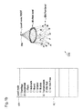
- Figure 1a shows a cone tree CT1 displaying the network information. Furthermore, Figure 1a shows a hierarchy list HL indicating different hierarchy levels in an order, which corresponds to the order of the hierarchy levels. Furthermore, Figure 1a shows a menu item SR for selecting a root node of the cone tree CT.
- a single node, called Local Node, is selected by the user as the root node RN of the cone tree CT1.
- the hierarchy levels which are selected from the list HL by the user, are hierarchy levels corresponding to equipment of the network node and corresponding to transmission entities of network node.
- the user has selected the hierarchy level to which modules correspond, as well as the hierarchy levels to which Ethernet Ports and data flows correspond.
- Network resources which are assigned to the some hierarchy level are displayed as nodes of the same sphere of a cone tree.
- Hierarchical dependencies between dependent network resources are indicated as displayed links connecting the nodes representing the dependent network resources.
- the cone tree CT1 is displayed, such that only nodes which represent network resources that belong to the selected hierarchy levels of the list HL are displayed.
- the local network node is displayed as the root node RN of the cone tree.
- nodes representing modules of the local node are displayed.
- Ethernet Ports belonging to the modules of the local node are displayed.
- nodes which represent the data flows belonging to the Ethernet Ports are displayed.
- no nodes are displayed.
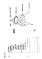
- Figure 1b shows a second cone tree CT2 together with a second hierarchy list HL'.
- the selected root SR of the cone tree CT2 is the same as for the cone tree CT1 in Figure 1 a.
- the hierarchy list HL' differs from the hierarchy list HL of Figure 1 a , in that the user has deselected the hierarchy level of data flow.
- the cone tree CT2 is displayed, such that no nodes at the hierarchy level of data flow are displayed. Furthermore, also no links indicating hierarchical dependencies of the nodes representing data flows are displayed.
- Fig 2a shows a cone tree CT3, which is the same as the cone tree CT1 of Fig 1a .
- the hierarchy list HL shown in Figure 2a indicates the same selection as the hierarchy list HL of Figure 1a
- the selected root SR of Figure 2a is the same as the selected root SR of Figure 1 a.
- Figure 2a indicates a selection of a network resource by a user.
- the user selects a network resource by checking the node that represents the network resource.
- the checking may be carried out by the user via an input device, for example a mouse.
- the user moves the mouse cursor over a node representing the network resource which he wants to select and then clicks the button of the mouse for checking the node and thus selecting the network resource.
- the cone tree CT4 which results from this selection is shown in Figure 2b .
- a hierarchy list HL and a selected root SR are shown in Figure 2b , which are identical to the hierarchy list HL and the selected root SR of the Figure 2a .
- the cone tree CT4, shown in Figure 2b contains only certain nodes that are displayed.
- the node that represents the selected network resource is displayed. Furthermore, nodes representing network resources, which are assigned to the selected hierarchy levels and which are directly or indirectly dependent on the selected network resource, are displayed. Therefore, in Figure 2b only those nodes at Ethernet Port level and data flow level, which have a direct or indirect hierarchical dependency on the selected resource are displayed. Furthermore, the direct or indirect hierarchical dependencies between the network resources, which are represented by displayed nodes, are indicated by links connecting the nodes representing the dependent network resources.
- the user has a tool at hand, for controlling the amount of displayed network information in a very efficient way.
- the user may select or deselect further hierarchy levels from the hierarchy list HL shown in Figure 2b , for further modifying the cone tree CT4 and thus causing a display or a hiding of nodes representing network resources at different hierarchy levels.
- the user may deselect the selected network resource in order to switch from the cone tree CT4 shown in Figure 2b back to the cone tree CT3 shown in Figure 2a .
- the user may select a different network resource by selecting the corresponding node in the cone tree CT3 of Figure 2a . Therefore, the user is able to swap between different displayed cone trees and different displayed amounts of network information in a very efficient manner.
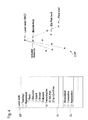
- Figure 3 shows the same hierarchy list H L and the same selected root SR as shown in Figure 2b . Furthermore, Figure 3 shows a dependency list DL, which indicates to the user different dependencies between network resources.
- One dependency is a hierarchical dependency between network resources.
- a further dependency is an established transmission connection between network resources.
- Another dependency is a configuration profile that is shared by network resources.
- the user can furthermore modify the displayed cone tree in order to arrive at a cone tree CT4' shown in Figure 3 , by selecting as a dependency transmission connections between network resources.
- the result is, that for the cone tree CT4' the some nodes which are already displayed in the cone tree CT4 are displayed, but different links connecting the displayed nodes are displayed.
- links indicating transmission connections between network resources of a some hierarchy level are displayed. Therefore, the cone tree CT4' contains only links, which indicate transmission connections of different data flows and furthermore links which indicate transmission connections of different Ethernet Ports.
- a dependency configuration profile which are shored by network resources of different levels.
- Such a configuration profile is for example an alarm profile, which is shared among different network resources.
- a profile is for example a set of parameters with respect to a function of a network resource,
- the displayed cone tree CT4 contains the same nodes as the cone tree CT4, but links, which indicate, which nodes have configuration profiles in common,
- the resulting cone tree that is then displayed is displayed in the same display area, at which previously the previous cone tree was displayed.
- the resulting cone tree is displayed, such that displayed nodes are displayed at the some locations within the display area, at which they were displayed before the selection or deselection by the user. This enables the user, to grasp in a very straightforward manner, in which way a selection or deselection carried out by him affects the displayed cone tree and thus affects the amount of network resources and the amount of network information displayed.
- Figure 5 shows a first embodiment of the device in the form of network node NN.
- the network node Via a network interface NI, the network node receives information about network resources of the network from other network nodes of the network or from a network management system.
- the network information is passed on to a network processor NP and written by the network processor NP into a memory M.
- the memory M stores the received network information as well as configuration data of the network node NN itself. For storing this information, the memory M uses a database DB,
- the node NN receives from other network nodes information about the other network nodes and the configuration of these network nodes via the network interface NI according to different protocols.
- a first protocol is the Open Shortest Path First Protocol, which is used for collecting topology information, as defined in the paper RFC 2328 (1998) and as updated by the paper RFC 5709 (2009).
- the protocol OSPF belongs to the Internet Protocol (IP) suite.
- IP Internet Protocol
- OSPF-TE Open Shortest Path First-Traffic Engineering
- IS-IS Intermediate System to Intermediate System
- CLNP Connectionless Network Protocol
- GPLS Generalized Multi Path Label Switching
- LMP Link Management Protocol
- RFC 4204 For using the LMP protocol in conjunction with the Internet Protocol, it is referred to the paper RFC 4204 (2005).
- the network information also called management information, which is collected by the network node NN from other network nodes as well as from the network management system (NMS) is stored within the database DB.
- the structure of the database is derived from the MIB information of each involved technologies.
- Another meta-language for defining network information is the Information Model (IM) for describing information exchanged by the Common Management Information Protocol (CMIP), as defined in the standard ITU-T X.711.
- CMIP Common Management Information Protocol
- the network interface NI supports the protocol for collecting network information according to the Transactional Language 1 (TL1) as defined in the document " GR-831-CORE, Language for Operations Application Messages, Issue 1, November 1996, Telcordia ".
- T1 Transactional Language 1
- the network processor NP retrieves and compiles from the network information stored within the database DB representation data which represents network resources of the network. Furthermore, the network processor NP generates configuration data which indicates a configuration of network resources of the network. Furthermore, the network processor NP generates assignment data, which assigns network resources to hierarchy levels of the network. Furthermore, the network processor NP generates declaration data, which declares dependencies between the network resources. The network processor NP does not necessarily have to generate the representation data, configuration data, assignment data and declaration data in the case that this data is already present within the database. The representation data, configuration data, assignment data and declaration data are also stored within the memory M.
- the network node NN contains furthermore a graphical processor GP, which generates data providing graphical representations.
- One kind of data is data providing a graphical representation of a cone tree.
- This graphical representation is generated by the graphical processor GP, such that network resources, which are assigned to a same hierarchy level, are represented by nodes of a same sphere of the cone tree.
- the graphical representation is generated, such that dependencies between dependent network resources are represented by links, which connect the nodes representing the dependent network resources.
- Further data for providing a graphical representation of a list of hierarchy levels is generated by the graphical processor GP.
- the different types of generated data providing the graphical representations may also be combined in one kind of data.
- the network node NN contains furthermore an input interface IIF, which is adapted to receive input signals from an input device.
- the input device is handled by a user for selecting one or more hierarchy levels from the list of hierarchy levels.
- the input signals received at the input interface IIF indicate a selection of hierarchy levels that is carried out by the user.
- the input interface IIF may be a separate interface, or it may be included within the network interface NI, in the case that the input signals are sent via the network to the network node NN. This may be the case, if the user is a network manager handling an input device that is connected to the manager's terminal, and the terminal then sends input signal via the network to the network node NN.
- the graphical processor GP Depending on the selection of hierarchy levels performed by the user, the graphical processor GP generates the graphical data providing a graphical representation of the cone free, such that only those nodes are contained in the cone tree, which represent network resources belonging to the selected hierarchy levels.
- the graphical data is passed on by the graphical processor GP to an output interface OIF of the network node NN.
- the output interface OIF may be a graphical interface, to which a display unit, such as a screen, may be connected.
- the output interface OIF which may be included within the network interface NI, is an interface for transmitting the graphical data via a network to a terminal.
- Such an exchange of graphical data between the network node NN and a terminal may be given in the form of a web service, wherein the network node NN acts as a server and the terminal acts as a client running a web-application.
- the network interface NI, the network processor NP, the input interface IIF, the graphical processor GP, the memory M and the output interface OIF of the network node NN are connected via a data bus D for exchanging data and signals between the different devices of the network node NN.
- the different hardware devices of the network node NN are connected with each other via a data bus
- Figure 6 shows a second embodiment of the proposed device in the form of a terminal T.
- the terminal T contains a network interface N12 via which the terminal T receives from a network node different data providing network information.
- This data includes representation data representing network resources of the network, configuration data indicating a configuration of the network resources, assignment data assigning network resources to hierarchy levels of the network, and declaration data declaring dependencies between the network resources.
- the terminal T receives from the network node the network information in the form of the mentioned data, and stores it in the form of a database DB that is stored in a memory M2.
- the database DC contains network information according to a meta-language such as the Management Information Base (MIB) or the information Model (IM).
- MIB Management Information Base
- IM information Model
- the network interface NI2 supports the SNMP protocol, the CMIP protocol and/or the protocol TL1.
- the terminal T contains furthermore a graphical processor GP2, which is adapted to generate graphical data providing a graphical representation of the cone tree, as previously described according to the embodiment of the network node. Furthermore, the graphical processor GP2 is adapted to generate graphical data providing a graphical representation of a list of hierarchy levels, as previously described according to the embodiment of the network node.
- the terminal T contains an input interface IIF2, via which the terminal T receives input signals from an input device which is used by the user.
- the input signals indicate a selection of one or more hierarchy levels from the list of hierarchy levels.
- the graphical processor GP2 passes the data providing graphical representations on to a graphical interface GI2 of the terminal T. Via the graphical interface GI2, signals are provided to a display unit, such as a screen.
- the graphical processor GP2 generates the graphical data providing a graphical representation of the cone tree, such that only such nodes are contained within the cone tree, which represent network resources belonging to the selected hierarchy levels.
- the different hardware devices of the terminal T are connected with each other via a databus D2.
- the network node NN shown in Figure 5 and the terminal T shown in Figure 6 are furthermore adapted to carry out further steps of the proposed method as previously described above.
Landscapes
- Engineering & Computer Science (AREA)
- Human Computer Interaction (AREA)
- Computer Networks & Wireless Communication (AREA)
- Signal Processing (AREA)
- User Interface Of Digital Computer (AREA)
- Computer And Data Communications (AREA)
- Data Exchanges In Wide-Area Networks (AREA)
Abstract
Description
- The invention relates to a method of displaying network information,
- For displaying information about network resources of a network, it is known to provide a graphical user interface to a user, for instance a network manager. Such a graphical user interface may make use of a three-dimensional cone tree for displaying information about network resources of a network.
- Depending on input actions taken by the user, the cone tree can be modified for displaying a modified amount of information. This allows the user to grasp the displayed information more easily.
- A method of displaying network information is proposed.
- A representation of network resources is provided. Furthermore, an assignment of the network resources to hierarchy levels of the network is provided. Further still, a declaration of dependencies between the network resources is provided.
- Network resources which are assigned to a same hierarchy level are displayed as nodes of a same sphere of a cone tree. Dependencies between dependent network resources are indicated as displayed links connecting the nodes representing the dependent network resources.
- A user is presented a list of hierarchy levels. The user selects hierarchy levels from the list. Only nodes which represent network resources that belong to the selected hierarchy levels are displayed.
- The proposed method has the advantage, that a user is able to easily modify the amount of displayed information, by selecting or deselecting hierarchy levels of network resources for controlling a display of the network resources of the selected or deselected hierarchy levels.
-
-
Figures 1a ,1b ,2a ,2b each show a cone tree with links indicating hierarchical dependencies as well as a list of hierarchy levels. -
Figure 3 shows a cone tree with links indicating transmission connections between the displayed nodes, a list of hierarchy levels and a list of dependencies. -
Figure 4 shows a cone tree with links indicating configuration profiles shared by network resources of different hierarchy levels, a list of hierarchy levels and a list of dependencies. -
Figure 5 shows a device for generating a graphical representation of network information according to a first embodiment. -
Figure 6 shows a device for generating a graphical representation of network information according to a second embodiment. - Proposed is a method of displaying network information, which relies on a cone tree containing different nodes, wherein each node represents a network resource of the network.
- In a network, a first type of network resources are network nodes of the network. Depending on the topology of the network, network nodes may be assigned to different sub-networks, wherein also a sub-network may contain further sub-networks, containing further nodes. Each network level or sub-network level of the network represents a hierarchy level to which a network node is assigned. Two nodes, which are connected to each other via a link and which belong to two neighboring hierarchy levels are defined as being hierarchically directly dependent. Furthermore, two network nodes which belong to non-neighboring hierarchy levels, and which can reach each other via multiple links of other network nodes by either only ascending or only descending through the hierarchy levels, are defined as being hierarchically indirectly dependent.
- Furthermore, a second type of network resources are the different types of equipment of a network node. The different types of equipment of the network nodes are also assigned to different hierarchy levels,
- To give examples, a highest hierarchy level of a network resources within a network node is displayed as a sphere whose nodes represent different racks of the network node. A next lower hierarchy level of network resources is then displayed as a next lower sphere whose nodes represent sub-racks or shelves of racks. The next lower hierarchy level of network resources is then displayed as a next lower sphere whose nodes represent boards belonging to sub-racks. A next lower hierarchy level of network resources is then displayed as a next lower sphere whose nodes represent drawers belonging to boards. A next lower hierarchy level of network resources is then displayed as a next lower sphere whose nodes represent modules belonging to drawers.
- Furthermore, a third type of network resources are transmission entities belonging to an equipment of a network node. The transmission entities are placed at hierarchy levels which are below the hierarchy levels of the equipment of a network node, For example, a hierarchy level of a transmission entity is defined by Ethernet Ports, belonging to modules. A transmission entity of a next lower level is then given as data flows, identified by VLAN tags, being associated with Ethernet Paris. Information about the different network resources of the network is assembled and made available, The information given in the form of data provides an assignment of network resources to hierarchy levels of the network. Furthermore, hierarchical dependencies between different network resources are provided.
-
Figure 1a shows a cone tree CT1 displaying the network information. Furthermore,Figure 1a shows a hierarchy list HL indicating different hierarchy levels in an order, which corresponds to the order of the hierarchy levels. Furthermore,Figure 1a shows a menu item SR for selecting a root node of the cone tree CT. - A single node, called Local Node, is selected by the user as the root node RN of the cone tree CT1. The hierarchy levels, which are selected from the list HL by the user, are hierarchy levels corresponding to equipment of the network node and corresponding to transmission entities of network node. The user has selected the hierarchy level to which modules correspond, as well as the hierarchy levels to which Ethernet Ports and data flows correspond.
- Network resources which are assigned to the some hierarchy level are displayed as nodes of the same sphere of a cone tree. Hierarchical dependencies between dependent network resources are indicated as displayed links connecting the nodes representing the dependent network resources.
- The cone tree CT1 is displayed, such that only nodes which represent network resources that belong to the selected hierarchy levels of the list HL are displayed.
- At the top of the cone tree CT1, the local network node is displayed as the root node RN of the cone tree. At the next lower sphere level of the cone tree CT1, nodes representing modules of the local node are displayed. At the next lower sphere level of the cone tree CT1, Ethernet Ports belonging to the modules of the local node are displayed. At the next lower level, nodes which represent the data flows belonging to the Ethernet Ports are displayed.
- For network resources, which belong to hierarchy levels that are not selected by the user, no nodes are displayed.
- Furthermore, only such links are displayed, which represent direct or indirect hierarchical dependencies of network resources, which are represented by displayed nodes.
-
Figure 1b shows a second cone tree CT2 together with a second hierarchy list HL'. The selected root SR of the cone tree CT2 is the same as for the cone tree CT1 inFigure 1 a. The hierarchy list HL' differs from the hierarchy list HL ofFigure 1 a , in that the user has deselected the hierarchy level of data flow. Thus, the cone tree CT2 is displayed, such that no nodes at the hierarchy level of data flow are displayed. Furthermore, also no links indicating hierarchical dependencies of the nodes representing data flows are displayed. -
Fig 2a shows a cone tree CT3, which is the same as the cone tree CT1 ofFig 1a . This is due to the fact, that also the hierarchy list HL shown inFigure 2a indicates the same selection as the hierarchy list HL ofFigure 1a , and the selected root SR ofFigure 2a is the same as the selected root SR ofFigure 1 a. - Furthermore,
Figure 2a indicates a selection of a network resource by a user. The user selects a network resource by checking the node that represents the network resource. The checking may be carried out by the user via an input device, for example a mouse. The user moves the mouse cursor over a node representing the network resource which he wants to select and then clicks the button of the mouse for checking the node and thus selecting the network resource. - The cone tree CT4 which results from this selection is shown in
Figure 2b . Furthermore, a hierarchy list HL and a selected root SR are shown inFigure 2b , which are identical to the hierarchy list HL and the selected root SR of theFigure 2a . - The cone tree CT4, shown in
Figure 2b contains only certain nodes that are displayed. - As a first node, the node that represents the selected network resource is displayed. Furthermore, nodes representing network resources, which are assigned to the selected hierarchy levels and which are directly or indirectly dependent on the selected network resource, are displayed. Therefore, in
Figure 2b only those nodes at Ethernet Port level and data flow level, which have a direct or indirect hierarchical dependency on the selected resource are displayed. Furthermore, the direct or indirect hierarchical dependencies between the network resources, which are represented by displayed nodes, are indicated by links connecting the nodes representing the dependent network resources. - By selecting a single network resource and thus generating a display of the cone tree CT4 as shown in
Figure 2b as described above, the user has a tool at hand, for controlling the amount of displayed network information in a very efficient way. The user may select or deselect further hierarchy levels from the hierarchy list HL shown inFigure 2b , for further modifying the cone tree CT4 and thus causing a display or a hiding of nodes representing network resources at different hierarchy levels. Even furthermore, the user may deselect the selected network resource in order to switch from the cone tree CT4 shown inFigure 2b back to the cone tree CT3 shown inFigure 2a . After this, the user may select a different network resource by selecting the corresponding node in the cone tree CT3 ofFigure 2a . Therefore, the user is able to swap between different displayed cone trees and different displayed amounts of network information in a very efficient manner. -
Figure 3 shows the same hierarchy list H L and the same selected root SR as shown inFigure 2b . Furthermore,Figure 3 shows a dependency list DL, which indicates to the user different dependencies between network resources.. One dependency is a hierarchical dependency between network resources. A further dependency is an established transmission connection between network resources. Another dependency is a configuration profile that is shared by network resources. - Having reached the display of the cone tree CT4 in
Figure 2b , the user can furthermore modify the displayed cone tree in order to arrive at a cone tree CT4' shown inFigure 3 , by selecting as a dependency transmission connections between network resources. The result is, that for the cone tree CT4' the some nodes which are already displayed in the cone tree CT4 are displayed, but different links connecting the displayed nodes are displayed. Now, for the cone tree CT4', links indicating transmission connections between network resources of a some hierarchy level are displayed. Therefore, the cone tree CT4' contains only links, which indicate transmission connections of different data flows and furthermore links which indicate transmission connections of different Ethernet Ports. - Instead of choosing from the dependency list DL the transmission connection of network resources, the user may select as a dependency configuration profiles, which are shored by network resources of different levels. Such a configuration profile is for example an alarm profile, which is shared among different network resources. A profile is for example a set of parameters with respect to a function of a network resource,
- Due to choosing as the dependencies configuration profiles shared between network resources, the displayed cone tree CT4" contains the same nodes as the cone tree CT4, but links, which indicate, which nodes have configuration profiles in common,
- By being able to choose as dependencies configuration profiles which are shared by network resources, the user is able to check in a very efficient manner, which network resources share a same configuration profile,
- When the user selects or deselects a hierarchy level or when the user selects or deselects a node for selecting or deselecting a network resource, the resulting cone tree that is then displayed, is displayed in the same display area, at which previously the previous cone tree was displayed.
- Furthermore, when the user selects or deselects a level or when the user selects or deselects a node for selecting or deselecting a network resource, the resulting cone tree is displayed, such that displayed nodes are displayed at the some locations within the display area, at which they were displayed before the selection or deselection by the user. This enables the user, to grasp in a very straightforward manner, in which way a selection or deselection carried out by him affects the displayed cone tree and thus affects the amount of network resources and the amount of network information displayed.
- Furthermore, a device for generating a graphical representation of network information is proposed.
-
Figure 5 shows a first embodiment of the device in the form of network node NN. Via a network interface NI, the network node receives information about network resources of the network from other network nodes of the network or from a network management system. The network information is passed on to a network processor NP and written by the network processor NP into a memory M. The memory M stores the received network information as well as configuration data of the network node NN itself. For storing this information, the memory M uses a database DB, - The node NN receives from other network nodes information about the other network nodes and the configuration of these network nodes via the network interface NI according to different protocols. A first protocol is the Open Shortest Path First Protocol, which is used for collecting topology information, as defined in the paper RFC 2328 (1998) and as updated by the paper RFC 5709 (2009). The protocol OSPF belongs to the Internet Protocol (IP) suite. For networks supporting the protocol Generalized Multipath Label Switching (GLMPS), the protocol Open Shortest Path First-Traffic Engineering (OSPF-TE) is supported by the network interface NI, as defined in the paper RFC 3630 (2003) and as updated by the paper RFC 4203 (2005).
- A further protocol for collecting network information via the network interface NI is the routing protocol Intermediate System to Intermediate System (IS-IS), as defined in the paper ISO/IEC 10589 (2002) for use with the Connectionless Network Protocol (CLNP), and as published in the paper RFC 1142 (1990) for use in conjunction with the Internet Protocol. An extension of IS-IS for support of Generalized Multi Path Label Switching (GMPLS) is defined in the paper RFC 5307 (2008).
- A further protocol for collection topology information is the Link Management Protocol (LMP). For using the LMP protocol in conjunction with the Internet Protocol, it is referred to the paper RFC 4204 (2005).
- The network information, also called management information, which is collected by the network node NN from other network nodes as well as from the network management system (NMS) is stored within the database DB. The Structure of Management Information (SMI), as described in the paper RFC 2578 (1999), and the Management Information Base (MIB), as described in the paper RFC 3418 (2002), are used for describing management information exchanged by the Simple Network Management Protocol (SNMP), as defined in the paper RFC 1157 (1990). The structure of the database is derived from the MIB information of each involved technologies. Another meta-language for defining network information is the Information Model (IM) for describing information exchanged by the Common Management Information Protocol (CMIP), as defined in the standard ITU-T X.711. For collecting information via the CMIP protocol, the network interface NI supports the CMIP protocol.
- Furthermore, the network interface NI supports the protocol for collecting network information according to the Transactional Language 1 (TL1) as defined in the document "GR-831-CORE, Language for Operations Application Messages, Issue 1, November 1996, Telcordia".
- The network processor NP retrieves and compiles from the network information stored within the database DB representation data which represents network resources of the network. Furthermore, the network processor NP generates configuration data which indicates a configuration of network resources of the network. Furthermore, the network processor NP generates assignment data, which assigns network resources to hierarchy levels of the network. Furthermore, the network processor NP generates declaration data, which declares dependencies between the network resources. The network processor NP does not necessarily have to generate the representation data, configuration data, assignment data and declaration data in the case that this data is already present within the database. The representation data, configuration data, assignment data and declaration data are also stored within the memory M.
- The network node NN contains furthermore a graphical processor GP, which generates data providing graphical representations. One kind of data is data providing a graphical representation of a cone tree. This graphical representation is generated by the graphical processor GP, such that network resources, which are assigned to a same hierarchy level, are represented by nodes of a same sphere of the cone tree. Furthermore, the graphical representation is generated, such that dependencies between dependent network resources are represented by links, which connect the nodes representing the dependent network resources.
- Further data for providing a graphical representation of a list of hierarchy levels is generated by the graphical processor GP. The different types of generated data providing the graphical representations may also be combined in one kind of data.
- The network node NN contains furthermore an input interface IIF, which is adapted to receive input signals from an input device. The input device is handled by a user for selecting one or more hierarchy levels from the list of hierarchy levels. Thus, the input signals received at the input interface IIF indicate a selection of hierarchy levels that is carried out by the user. The input interface IIF may be a separate interface, or it may be included within the network interface NI, in the case that the input signals are sent via the network to the network node NN. This may be the case, if the user is a network manager handling an input device that is connected to the manager's terminal, and the terminal then sends input signal via the network to the network node NN.
- Depending on the selection of hierarchy levels performed by the user, the graphical processor GP generates the graphical data providing a graphical representation of the cone free, such that only those nodes are contained in the cone tree, which represent network resources belonging to the selected hierarchy levels.
- For providing the graphical data to a display unit, the graphical data is passed on by the graphical processor GP to an output interface OIF of the network node NN. The output interface OIF may be a graphical interface, to which a display unit, such as a screen, may be connected. Alternatively, the output interface OIF, which may be included within the network interface NI, is an interface for transmitting the graphical data via a network to a terminal. Such an exchange of graphical data between the network node NN and a terminal may be given in the form of a web service, wherein the network node NN acts as a server and the terminal acts as a client running a web-application. The network interface NI, the network processor NP, the input interface IIF, the graphical processor GP, the memory M and the output interface OIF of the network node NN are connected via a data bus D for exchanging data and signals between the different devices of the network node NN.
- The different hardware devices of the network node NN are connected with each other via a data bus
-
Figure 6 shows a second embodiment of the proposed device in the form of a terminal T. The terminal T contains a network interface N12 via which the terminal T receives from a network node different data providing network information. This data includes representation data representing network resources of the network, configuration data indicating a configuration of the network resources, assignment data assigning network resources to hierarchy levels of the network, and declaration data declaring dependencies between the network resources. - The terminal T receives from the network node the network information in the form of the mentioned data, and stores it in the form of a database DB that is stored in a memory M2. The database DC contains network information according to a meta-language such as the Management Information Base (MIB) or the information Model (IM). For receiving the network information, the network interface NI2 supports the SNMP protocol, the CMIP protocol and/or the protocol TL1.
- The terminal T contains furthermore a graphical processor GP2, which is adapted to generate graphical data providing a graphical representation of the cone tree, as previously described according to the embodiment of the network node. Furthermore, the graphical processor GP2 is adapted to generate graphical data providing a graphical representation of a list of hierarchy levels, as previously described according to the embodiment of the network node.
- The terminal T contains an input interface IIF2, via which the terminal T receives input signals from an input device which is used by the user. The input signals indicate a selection of one or more hierarchy levels from the list of hierarchy levels.
- The graphical processor GP2 passes the data providing graphical representations on to a graphical interface GI2 of the terminal T. Via the graphical interface GI2, signals are provided to a display unit, such as a screen.
- The graphical processor GP2 generates the graphical data providing a graphical representation of the cone tree, such that only such nodes are contained within the cone tree, which represent network resources belonging to the selected hierarchy levels.
- The different hardware devices of the terminal T are connected with each other via a databus D2.
- The network node NN shown in
Figure 5 and the terminal T shown inFigure 6 are furthermore adapted to carry out further steps of the proposed method as previously described above.
Claims (8)
- Method of displaying network information,
comprising the steps of- providing a representation of network resources,- providing un assignment of said network resources to hierarchy levels of said network,- providing a declaration of dependencies between said network resources, wherein network resources assigned to a same hierarchy level are displayed as nodes of a some sphere of a cone tree (CT1), wherein said dependencies between dependent network resources are indicated as displayed links connecting the nodes representing said dependent network resources.- presenting a user a list of hierarchy levels (HL),- upon selection of one or more hierarchy levels from said list by said user, displaying only nodes representing network resources that belong to said selected hierarchy levels. - Method according to claim 1,
wherein only such links are displayed, which indicate a direct or indirect dependency of network resources that are represented by said displayed nodes. - Method according to claim 2,
comprising the further step of- upon a selection of a network resource (selected resource) by a checking of a node representing said network resource by said user, displaying only the checked node representing the selected network resource, and nodes representing network resources, which are assigned to said selected hierarchy levels and which are directly or indirectly dependent on said selected network resource. - Method according to claim 3,
comprising the further steps of- providing different declaration of different types of dependencies between network resources,- presenting to said user a second list (DL) indicating said different types of dependencies,- upon a selection of a type of dependencies from said list by said user, displaying only such links, which indicate dependencies of the selected type between network resources that are represented by the displayed nodes. - Method according to claim 4,
wherein said types of dependencies between network resources include hierarchical dependencies between network resources of different hierarchy levels, transmission connections between network resources of a same hierarchy level, and configuration profiles shared by network resources of different hierarchy levels. - Method according to claim 1 to 5,
wherein said cone tree (C1, ..., CT4, CT4', CT4") is displayed in a display area, and wherein after a selection or a deselection of one or more hierarchy levels, or
a selection of a node representing a network resource, said cone tree (C1, ..., CT4, CT4', CT4") is displayed in said same display area. - Method according to claim 6,
wherein after a selection or deselection of one or more hierarchy levels, or
a selection of a node representing a network resource,
nodes, which are displayed after said selection or deselection, are displayed at the same locations of said display area, at which they were displayed before said selection or deselection. - Device (NN, T) for generating a graphical representation of network information, comprising- a memory (M, M2) adapted to store and to provide- configuration data indicating a configuration of network resources of a network,- assignment data assigning said network resources to hierarchy levels, and- declaration data declaring dependencies between said network resources
furthermore comprising- a graphical processor (GP, GP2) adapted to generate first graphical data providing a graphical representation of a cone tree, such that network resources assigned to a same hierarchy level arc contained in said graphical representation as node of a same sphere of said cone tree, and such that said dependencies between dependent network resources are contained in said graphical representation as links connecting the nodes representing said dependent network resources, and
second graphical data providing a graphical representation of a list of hierarchy levels,
furthermore comprising- an input interface (IIF, IIF2) adapted to receive input signals, said input signals indicating a selection of one or more hierarchy levels from said list of hierarchy levels by a user,
wherein said graphical processor (GP, GP2) is configured to generate said first graphical data, such that only such nodes, which represent network resources belonging to said selected hierarchy levels, are contained in said graphical representation of said cone tree.
Priority Applications (1)
| Application Number | Priority Date | Filing Date | Title |
|---|---|---|---|
| EP20090306263 EP2337267B1 (en) | 2009-12-18 | 2009-12-18 | Method of displaying network information |
Applications Claiming Priority (1)
| Application Number | Priority Date | Filing Date | Title |
|---|---|---|---|
| EP20090306263 EP2337267B1 (en) | 2009-12-18 | 2009-12-18 | Method of displaying network information |
Publications (2)
| Publication Number | Publication Date |
|---|---|
| EP2337267A1 true EP2337267A1 (en) | 2011-06-22 |
| EP2337267B1 EP2337267B1 (en) | 2013-06-12 |
Family
ID=42046284
Family Applications (1)
| Application Number | Title | Priority Date | Filing Date |
|---|---|---|---|
| EP20090306263 Not-in-force EP2337267B1 (en) | 2009-12-18 | 2009-12-18 | Method of displaying network information |
Country Status (1)
| Country | Link |
|---|---|
| EP (1) | EP2337267B1 (en) |
Citations (3)
| Publication number | Priority date | Publication date | Assignee | Title |
|---|---|---|---|---|
| EP1094635A2 (en) * | 1999-10-19 | 2001-04-25 | Nortel Networks Limited | Apparatus and method for selecting network entities |
| US20020113816A1 (en) * | 1998-12-09 | 2002-08-22 | Frederick H. Mitchell | Method and apparatus providing a graphical user interface for representing and navigating hierarchical networks |
| US6484190B1 (en) * | 1998-07-01 | 2002-11-19 | International Business Machines Corporation | Subset search tree integrated graphical interface |
-
2009
- 2009-12-18 EP EP20090306263 patent/EP2337267B1/en not_active Not-in-force
Patent Citations (3)
| Publication number | Priority date | Publication date | Assignee | Title |
|---|---|---|---|---|
| US6484190B1 (en) * | 1998-07-01 | 2002-11-19 | International Business Machines Corporation | Subset search tree integrated graphical interface |
| US20020113816A1 (en) * | 1998-12-09 | 2002-08-22 | Frederick H. Mitchell | Method and apparatus providing a graphical user interface for representing and navigating hierarchical networks |
| EP1094635A2 (en) * | 1999-10-19 | 2001-04-25 | Nortel Networks Limited | Apparatus and method for selecting network entities |
Also Published As
| Publication number | Publication date |
|---|---|
| EP2337267B1 (en) | 2013-06-12 |
Similar Documents
| Publication | Publication Date | Title |
|---|---|---|
| US10700958B2 (en) | Network management system with traffic engineering for a software defined network | |
| US8611232B2 (en) | Method of simple and efficient failure resilient load balancing | |
| US10825212B2 (en) | Enhanced user interface systems including dynamic context selection for cloud-based networks | |
| EP1393503B1 (en) | Method and system for determining network characteristics using routing protocols | |
| EP2586157B1 (en) | Network management | |
| EP2371094B1 (en) | Method and communication apparatus for generating summarised network topology parameters | |
| US9674045B2 (en) | Methods, systems, and computer readable media for modeling packet technology services using a packet virtual network (PVN) | |
| JP5256406B2 (en) | Network visualization method and network visualization device | |
| US20020021675A1 (en) | System and method for packet network configuration debugging and database | |
| CN111654438B (en) | A method, controller and system for establishing a forwarding path in a network | |
| KR20140147860A (en) | Synchronization management groups | |
| KR20140136520A (en) | Synchronization topology and route analytics integration | |
| US20150370848A1 (en) | System and method for managing data integrity in electronic data storage | |
| CN104539445B (en) | A kind of method and apparatus for management business resource | |
| CN108924011A (en) | Monitoring system, relevant device, method and medium for OSPF+ Routing Protocol | |
| CN105591798A (en) | Method and device for transmitting OAM information in DCN | |
| US9391872B2 (en) | Route topology discovery in data networks | |
| US7779123B2 (en) | System and method for building network model in network management application | |
| US8750166B2 (en) | Route topology discovery in data networks | |
| EP2337267B1 (en) | Method of displaying network information | |
| JP2006135686A (en) | Network failure recovery management method and network failure recovery management device | |
| Maier et al. | Multi-domain routing techniques with topology aggregation in ASON networks | |
| Xu et al. | Generalized MPLS-based distributed control architecture for automatically switched transport networks | |
| Lim et al. | Model of transport SDN and MPLS-TP for T-SDN controller | |
| EP2437441B1 (en) | A method for generating a look-up table for retrieving data rates for a data transmission connection |
Legal Events
| Date | Code | Title | Description |
|---|---|---|---|
| PUAI | Public reference made under article 153(3) epc to a published international application that has entered the european phase |
Free format text: ORIGINAL CODE: 0009012 |
|
| 17P | Request for examination filed |
Effective date: 20110121 |
|
| AK | Designated contracting states |
Kind code of ref document: A1 Designated state(s): AT BE BG CH CY CZ DE DK EE ES FI FR GB GR HR HU IE IS IT LI LT LU LV MC MK MT NL NO PL PT RO SE SI SK SM TR |
|
| RAP1 | Party data changed (applicant data changed or rights of an application transferred) |
Owner name: ALCATEL LUCENT |
|
| GRAP | Despatch of communication of intention to grant a patent |
Free format text: ORIGINAL CODE: EPIDOSNIGR1 |
|
| RIC1 | Information provided on ipc code assigned before grant |
Ipc: H04L 12/24 20060101AFI20121206BHEP |
|
| GRAS | Grant fee paid |
Free format text: ORIGINAL CODE: EPIDOSNIGR3 |
|
| GRAA | (expected) grant |
Free format text: ORIGINAL CODE: 0009210 |
|
| AK | Designated contracting states |
Kind code of ref document: B1 Designated state(s): AT BE BG CH CY CZ DE DK EE ES FI FR GB GR HR HU IE IS IT LI LT LU LV MC MK MT NL NO PL PT RO SE SI SK SM TR |
|
| REG | Reference to a national code |
Ref country code: GB Ref legal event code: FG4D |
|
| REG | Reference to a national code |
Ref country code: CH Ref legal event code: EP |
|
| REG | Reference to a national code |
Ref country code: AT Ref legal event code: REF Ref document number: 617037 Country of ref document: AT Kind code of ref document: T Effective date: 20130615 |
|
| REG | Reference to a national code |
Ref country code: IE Ref legal event code: FG4D |
|
| REG | Reference to a national code |
Ref country code: DE Ref legal event code: R096 Ref document number: 602009016357 Country of ref document: DE Effective date: 20130808 |
|
| 111Z | Information provided on other rights and legal means of execution |
Free format text: AT BE BG CH CY CZ DE DK EE ES FI FR GB GR HR HU IE IS IT LI LT LU LV MC MK MT NL NO PL PT RO SE SI SK SM TR Effective date: 20130410 |
|
| PG25 | Lapsed in a contracting state [announced via postgrant information from national office to epo] |
Ref country code: NO Free format text: LAPSE BECAUSE OF FAILURE TO SUBMIT A TRANSLATION OF THE DESCRIPTION OR TO PAY THE FEE WITHIN THE PRESCRIBED TIME-LIMIT Effective date: 20130912 Ref country code: GR Free format text: LAPSE BECAUSE OF FAILURE TO SUBMIT A TRANSLATION OF THE DESCRIPTION OR TO PAY THE FEE WITHIN THE PRESCRIBED TIME-LIMIT Effective date: 20130913 Ref country code: SE Free format text: LAPSE BECAUSE OF FAILURE TO SUBMIT A TRANSLATION OF THE DESCRIPTION OR TO PAY THE FEE WITHIN THE PRESCRIBED TIME-LIMIT Effective date: 20130612 Ref country code: ES Free format text: LAPSE BECAUSE OF FAILURE TO SUBMIT A TRANSLATION OF THE DESCRIPTION OR TO PAY THE FEE WITHIN THE PRESCRIBED TIME-LIMIT Effective date: 20130923 Ref country code: LT Free format text: LAPSE BECAUSE OF FAILURE TO SUBMIT A TRANSLATION OF THE DESCRIPTION OR TO PAY THE FEE WITHIN THE PRESCRIBED TIME-LIMIT Effective date: 20130612 Ref country code: FI Free format text: LAPSE BECAUSE OF FAILURE TO SUBMIT A TRANSLATION OF THE DESCRIPTION OR TO PAY THE FEE WITHIN THE PRESCRIBED TIME-LIMIT Effective date: 20130612 Ref country code: SI Free format text: LAPSE BECAUSE OF FAILURE TO SUBMIT A TRANSLATION OF THE DESCRIPTION OR TO PAY THE FEE WITHIN THE PRESCRIBED TIME-LIMIT Effective date: 20130612 |
|
| REG | Reference to a national code |
Ref country code: AT Ref legal event code: MK05 Ref document number: 617037 Country of ref document: AT Kind code of ref document: T Effective date: 20130612 |
|
| REG | Reference to a national code |
Ref country code: NL Ref legal event code: VDEP Effective date: 20130612 |
|
| REG | Reference to a national code |
Ref country code: LT Ref legal event code: MG4D |
|
| PG25 | Lapsed in a contracting state [announced via postgrant information from national office to epo] |
Ref country code: BG Free format text: LAPSE BECAUSE OF FAILURE TO SUBMIT A TRANSLATION OF THE DESCRIPTION OR TO PAY THE FEE WITHIN THE PRESCRIBED TIME-LIMIT Effective date: 20130912 Ref country code: HR Free format text: LAPSE BECAUSE OF FAILURE TO SUBMIT A TRANSLATION OF THE DESCRIPTION OR TO PAY THE FEE WITHIN THE PRESCRIBED TIME-LIMIT Effective date: 20130612 |
|
| PG25 | Lapsed in a contracting state [announced via postgrant information from national office to epo] |
Ref country code: LV Free format text: LAPSE BECAUSE OF FAILURE TO SUBMIT A TRANSLATION OF THE DESCRIPTION OR TO PAY THE FEE WITHIN THE PRESCRIBED TIME-LIMIT Effective date: 20130612 |
|
| PG25 | Lapsed in a contracting state [announced via postgrant information from national office to epo] |
Ref country code: CZ Free format text: LAPSE BECAUSE OF FAILURE TO SUBMIT A TRANSLATION OF THE DESCRIPTION OR TO PAY THE FEE WITHIN THE PRESCRIBED TIME-LIMIT Effective date: 20130612 Ref country code: PT Free format text: LAPSE BECAUSE OF FAILURE TO SUBMIT A TRANSLATION OF THE DESCRIPTION OR TO PAY THE FEE WITHIN THE PRESCRIBED TIME-LIMIT Effective date: 20131014 Ref country code: AT Free format text: LAPSE BECAUSE OF FAILURE TO SUBMIT A TRANSLATION OF THE DESCRIPTION OR TO PAY THE FEE WITHIN THE PRESCRIBED TIME-LIMIT Effective date: 20130612 Ref country code: SK Free format text: LAPSE BECAUSE OF FAILURE TO SUBMIT A TRANSLATION OF THE DESCRIPTION OR TO PAY THE FEE WITHIN THE PRESCRIBED TIME-LIMIT Effective date: 20130612 Ref country code: EE Free format text: LAPSE BECAUSE OF FAILURE TO SUBMIT A TRANSLATION OF THE DESCRIPTION OR TO PAY THE FEE WITHIN THE PRESCRIBED TIME-LIMIT Effective date: 20130612 Ref country code: IS Free format text: LAPSE BECAUSE OF FAILURE TO SUBMIT A TRANSLATION OF THE DESCRIPTION OR TO PAY THE FEE WITHIN THE PRESCRIBED TIME-LIMIT Effective date: 20131012 Ref country code: BE Free format text: LAPSE BECAUSE OF FAILURE TO SUBMIT A TRANSLATION OF THE DESCRIPTION OR TO PAY THE FEE WITHIN THE PRESCRIBED TIME-LIMIT Effective date: 20130612 |
|
| PG25 | Lapsed in a contracting state [announced via postgrant information from national office to epo] |
Ref country code: PL Free format text: LAPSE BECAUSE OF FAILURE TO SUBMIT A TRANSLATION OF THE DESCRIPTION OR TO PAY THE FEE WITHIN THE PRESCRIBED TIME-LIMIT Effective date: 20130612 Ref country code: RO Free format text: LAPSE BECAUSE OF FAILURE TO SUBMIT A TRANSLATION OF THE DESCRIPTION OR TO PAY THE FEE WITHIN THE PRESCRIBED TIME-LIMIT Effective date: 20130612 Ref country code: NL Free format text: LAPSE BECAUSE OF FAILURE TO SUBMIT A TRANSLATION OF THE DESCRIPTION OR TO PAY THE FEE WITHIN THE PRESCRIBED TIME-LIMIT Effective date: 20130612 |
|
| PLBE | No opposition filed within time limit |
Free format text: ORIGINAL CODE: 0009261 |
|
| STAA | Information on the status of an ep patent application or granted ep patent |
Free format text: STATUS: NO OPPOSITION FILED WITHIN TIME LIMIT |
|
| PG25 | Lapsed in a contracting state [announced via postgrant information from national office to epo] |
Ref country code: DK Free format text: LAPSE BECAUSE OF FAILURE TO SUBMIT A TRANSLATION OF THE DESCRIPTION OR TO PAY THE FEE WITHIN THE PRESCRIBED TIME-LIMIT Effective date: 20130612 |
|
| 26N | No opposition filed |
Effective date: 20140313 |
|
| PG25 | Lapsed in a contracting state [announced via postgrant information from national office to epo] |
Ref country code: IT Free format text: LAPSE BECAUSE OF FAILURE TO SUBMIT A TRANSLATION OF THE DESCRIPTION OR TO PAY THE FEE WITHIN THE PRESCRIBED TIME-LIMIT Effective date: 20130612 |
|
| REG | Reference to a national code |
Ref country code: DE Ref legal event code: R097 Ref document number: 602009016357 Country of ref document: DE Effective date: 20140313 |
|
| REG | Reference to a national code |
Ref country code: CH Ref legal event code: PL |
|
| PG25 | Lapsed in a contracting state [announced via postgrant information from national office to epo] |
Ref country code: LU Free format text: LAPSE BECAUSE OF FAILURE TO SUBMIT A TRANSLATION OF THE DESCRIPTION OR TO PAY THE FEE WITHIN THE PRESCRIBED TIME-LIMIT Effective date: 20131218 |
|
| REG | Reference to a national code |
Ref country code: IE Ref legal event code: MM4A |
|
| PG25 | Lapsed in a contracting state [announced via postgrant information from national office to epo] |
Ref country code: IE Free format text: LAPSE BECAUSE OF NON-PAYMENT OF DUE FEES Effective date: 20131218 Ref country code: CH Free format text: LAPSE BECAUSE OF NON-PAYMENT OF DUE FEES Effective date: 20131231 Ref country code: LI Free format text: LAPSE BECAUSE OF NON-PAYMENT OF DUE FEES Effective date: 20131231 |
|
| PG25 | Lapsed in a contracting state [announced via postgrant information from national office to epo] |
Ref country code: SM Free format text: LAPSE BECAUSE OF FAILURE TO SUBMIT A TRANSLATION OF THE DESCRIPTION OR TO PAY THE FEE WITHIN THE PRESCRIBED TIME-LIMIT Effective date: 20130612 |
|
| PG25 | Lapsed in a contracting state [announced via postgrant information from national office to epo] |
Ref country code: CY Free format text: LAPSE BECAUSE OF FAILURE TO SUBMIT A TRANSLATION OF THE DESCRIPTION OR TO PAY THE FEE WITHIN THE PRESCRIBED TIME-LIMIT Effective date: 20130612 Ref country code: TR Free format text: LAPSE BECAUSE OF FAILURE TO SUBMIT A TRANSLATION OF THE DESCRIPTION OR TO PAY THE FEE WITHIN THE PRESCRIBED TIME-LIMIT Effective date: 20130612 |
|
| PG25 | Lapsed in a contracting state [announced via postgrant information from national office to epo] |
Ref country code: MK Free format text: LAPSE BECAUSE OF FAILURE TO SUBMIT A TRANSLATION OF THE DESCRIPTION OR TO PAY THE FEE WITHIN THE PRESCRIBED TIME-LIMIT Effective date: 20130612 Ref country code: HU Free format text: LAPSE BECAUSE OF FAILURE TO SUBMIT A TRANSLATION OF THE DESCRIPTION OR TO PAY THE FEE WITHIN THE PRESCRIBED TIME-LIMIT; INVALID AB INITIO Effective date: 20091218 Ref country code: MC Free format text: LAPSE BECAUSE OF FAILURE TO SUBMIT A TRANSLATION OF THE DESCRIPTION OR TO PAY THE FEE WITHIN THE PRESCRIBED TIME-LIMIT Effective date: 20130612 |
|
| PG25 | Lapsed in a contracting state [announced via postgrant information from national office to epo] |
Ref country code: MT Free format text: LAPSE BECAUSE OF FAILURE TO SUBMIT A TRANSLATION OF THE DESCRIPTION OR TO PAY THE FEE WITHIN THE PRESCRIBED TIME-LIMIT Effective date: 20130612 |
|
| REG | Reference to a national code |
Ref country code: FR Ref legal event code: PLFP Year of fee payment: 7 |
|
| REG | Reference to a national code |
Ref country code: FR Ref legal event code: PLFP Year of fee payment: 8 |
|
| PGFP | Annual fee paid to national office [announced via postgrant information from national office to epo] |
Ref country code: FR Payment date: 20161222 Year of fee payment: 8 |
|
| REG | Reference to a national code |
Ref country code: FR Ref legal event code: ST Effective date: 20180831 |
|
| PG25 | Lapsed in a contracting state [announced via postgrant information from national office to epo] |
Ref country code: FR Free format text: LAPSE BECAUSE OF NON-PAYMENT OF DUE FEES Effective date: 20180102 |
|
| REG | Reference to a national code |
Ref country code: GB Ref legal event code: 732E Free format text: REGISTERED BETWEEN 20190429 AND 20190502 |
|
| REG | Reference to a national code |
Ref country code: DE Ref legal event code: R082 Ref document number: 602009016357 Country of ref document: DE Representative=s name: MENZIETTI WETZEL, DE Ref country code: DE Ref legal event code: R081 Ref document number: 602009016357 Country of ref document: DE Owner name: PROVENANCE ASSET GROUP LLC, PITTSFORD, US Free format text: FORMER OWNER: ALCATEL LUCENT, PARIS, FR |
|
| PGFP | Annual fee paid to national office [announced via postgrant information from national office to epo] |
Ref country code: GB Payment date: 20201029 Year of fee payment: 12 Ref country code: DE Payment date: 20201027 Year of fee payment: 12 |
|
| REG | Reference to a national code |
Ref country code: DE Ref legal event code: R079 Ref document number: 602009016357 Country of ref document: DE Free format text: PREVIOUS MAIN CLASS: H04L0012240000 Ipc: H04L0041000000 |
|
| REG | Reference to a national code |
Ref country code: DE Ref legal event code: R119 Ref document number: 602009016357 Country of ref document: DE |
|
| GBPC | Gb: european patent ceased through non-payment of renewal fee |
Effective date: 20211218 |
|
| PG25 | Lapsed in a contracting state [announced via postgrant information from national office to epo] |
Ref country code: GB Free format text: LAPSE BECAUSE OF NON-PAYMENT OF DUE FEES Effective date: 20211218 Ref country code: DE Free format text: LAPSE BECAUSE OF NON-PAYMENT OF DUE FEES Effective date: 20220701 |