EP2371094B1 - Method and communication apparatus for generating summarised network topology parameters - Google Patents
Method and communication apparatus for generating summarised network topology parameters Download PDFInfo
- Publication number
- EP2371094B1 EP2371094B1 EP08875411.4A EP08875411A EP2371094B1 EP 2371094 B1 EP2371094 B1 EP 2371094B1 EP 08875411 A EP08875411 A EP 08875411A EP 2371094 B1 EP2371094 B1 EP 2371094B1
- Authority
- EP
- European Patent Office
- Prior art keywords
- network
- path
- nodes
- bandwidth
- summarised
- Prior art date
- Legal status (The legal status is an assumption and is not a legal conclusion. Google has not performed a legal analysis and makes no representation as to the accuracy of the status listed.)
- Not-in-force
Links
Images


Classifications
-
- H—ELECTRICITY
- H04—ELECTRIC COMMUNICATION TECHNIQUE
- H04L—TRANSMISSION OF DIGITAL INFORMATION, e.g. TELEGRAPHIC COMMUNICATION
- H04L41/00—Arrangements for maintenance, administration or management of data switching networks, e.g. of packet switching networks
- H04L41/12—Discovery or management of network topologies
-
- H—ELECTRICITY
- H04—ELECTRIC COMMUNICATION TECHNIQUE
- H04L—TRANSMISSION OF DIGITAL INFORMATION, e.g. TELEGRAPHIC COMMUNICATION
- H04L12/00—Data switching networks
- H04L12/28—Data switching networks characterised by path configuration, e.g. LAN [Local Area Networks] or WAN [Wide Area Networks]
- H04L12/40—Bus networks
- H04L12/4013—Management of data rate on the bus
-
- H—ELECTRICITY
- H04—ELECTRIC COMMUNICATION TECHNIQUE
- H04L—TRANSMISSION OF DIGITAL INFORMATION, e.g. TELEGRAPHIC COMMUNICATION
- H04L41/00—Arrangements for maintenance, administration or management of data switching networks, e.g. of packet switching networks
- H04L41/08—Configuration management of networks or network elements
- H04L41/0896—Bandwidth or capacity management, i.e. automatically increasing or decreasing capacities
-
- H—ELECTRICITY
- H04—ELECTRIC COMMUNICATION TECHNIQUE
- H04L—TRANSMISSION OF DIGITAL INFORMATION, e.g. TELEGRAPHIC COMMUNICATION
- H04L45/00—Routing or path finding of packets in data switching networks
- H04L45/02—Topology update or discovery
-
- H—ELECTRICITY
- H04—ELECTRIC COMMUNICATION TECHNIQUE
- H04L—TRANSMISSION OF DIGITAL INFORMATION, e.g. TELEGRAPHIC COMMUNICATION
- H04L45/00—Routing or path finding of packets in data switching networks
- H04L45/02—Topology update or discovery
- H04L45/028—Dynamic adaptation of the update intervals, e.g. event-triggered updates
-
- H—ELECTRICITY
- H04—ELECTRIC COMMUNICATION TECHNIQUE
- H04L—TRANSMISSION OF DIGITAL INFORMATION, e.g. TELEGRAPHIC COMMUNICATION
- H04L45/00—Routing or path finding of packets in data switching networks
- H04L45/02—Topology update or discovery
- H04L45/033—Topology update or discovery by updating distance vector protocols
-
- H—ELECTRICITY
- H04—ELECTRIC COMMUNICATION TECHNIQUE
- H04L—TRANSMISSION OF DIGITAL INFORMATION, e.g. TELEGRAPHIC COMMUNICATION
- H04L45/00—Routing or path finding of packets in data switching networks
- H04L45/02—Topology update or discovery
- H04L45/04—Interdomain routing, e.g. hierarchical routing
-
- H—ELECTRICITY
- H04—ELECTRIC COMMUNICATION TECHNIQUE
- H04L—TRANSMISSION OF DIGITAL INFORMATION, e.g. TELEGRAPHIC COMMUNICATION
- H04L45/00—Routing or path finding of packets in data switching networks
- H04L45/24—Multipath
-
- H—ELECTRICITY
- H04—ELECTRIC COMMUNICATION TECHNIQUE
- H04L—TRANSMISSION OF DIGITAL INFORMATION, e.g. TELEGRAPHIC COMMUNICATION
- H04L45/00—Routing or path finding of packets in data switching networks
- H04L45/24—Multipath
- H04L45/245—Link aggregation, e.g. trunking
-
- H—ELECTRICITY
- H04—ELECTRIC COMMUNICATION TECHNIQUE
- H04L—TRANSMISSION OF DIGITAL INFORMATION, e.g. TELEGRAPHIC COMMUNICATION
- H04L45/00—Routing or path finding of packets in data switching networks
- H04L45/30—Routing of multiclass traffic
-
- H—ELECTRICITY
- H04—ELECTRIC COMMUNICATION TECHNIQUE
- H04L—TRANSMISSION OF DIGITAL INFORMATION, e.g. TELEGRAPHIC COMMUNICATION
- H04L12/00—Data switching networks
- H04L12/28—Data switching networks characterised by path configuration, e.g. LAN [Local Area Networks] or WAN [Wide Area Networks]
- H04L12/2854—Wide area networks, e.g. public data networks
- H04L12/2856—Access arrangements, e.g. Internet access
- H04L12/2863—Arrangements for combining access network resources elements, e.g. channel bonding
- H04L12/2865—Logical combinations
-
- H—ELECTRICITY
- H04—ELECTRIC COMMUNICATION TECHNIQUE
- H04L—TRANSMISSION OF DIGITAL INFORMATION, e.g. TELEGRAPHIC COMMUNICATION
- H04L12/00—Data switching networks
- H04L12/28—Data switching networks characterised by path configuration, e.g. LAN [Local Area Networks] or WAN [Wide Area Networks]
- H04L12/2854—Wide area networks, e.g. public data networks
- H04L12/2856—Access arrangements, e.g. Internet access
- H04L12/2863—Arrangements for combining access network resources elements, e.g. channel bonding
- H04L12/2867—Physical combinations
-
- Y—GENERAL TAGGING OF NEW TECHNOLOGICAL DEVELOPMENTS; GENERAL TAGGING OF CROSS-SECTIONAL TECHNOLOGIES SPANNING OVER SEVERAL SECTIONS OF THE IPC; TECHNICAL SUBJECTS COVERED BY FORMER USPC CROSS-REFERENCE ART COLLECTIONS [XRACs] AND DIGESTS
- Y02—TECHNOLOGIES OR APPLICATIONS FOR MITIGATION OR ADAPTATION AGAINST CLIMATE CHANGE
- Y02D—CLIMATE CHANGE MITIGATION TECHNOLOGIES IN INFORMATION AND COMMUNICATION TECHNOLOGIES [ICT], I.E. INFORMATION AND COMMUNICATION TECHNOLOGIES AIMING AT THE REDUCTION OF THEIR OWN ENERGY USE
- Y02D30/00—Reducing energy consumption in communication networks
- Y02D30/50—Reducing energy consumption in communication networks in wire-line communication networks, e.g. low power modes or reduced link rate
Definitions
- the invention relates to a method of generating summarised network topology parameters of a communications network domain and a communications monitoring apparatus for monitoring a communications network domain.
- automatic switched optical communications networks comprising a plurality of network nodes with interconnecting links between respective pairs of nodes
- topology information in automatic switched transport networks (ASTN) this is carried out using a routing protocol such as open shortest path first (OSPF).
- OSPF open shortest path first
- the topology information is required by path computation elements within the network domains for computing paths through the network, including alternative paths to restore failed circuits in case a fault is detected in the network and the fault affects the route of one or more signaled paths.
- the reachability of resources is taken into account together with the characteristics of each interconnecting link reported by the routing protocol.
- the time required to carry out a path computation is a function of the number of nodes and interconnecting links in the network.
- the paths may be determined using a modified Dijkstra algorithm, using the Landau notation, which has a running time equal to O(L 2 ), where L is the number of interconnecting links. This means that in big networks the running time of the algorithm can become long, causing higher traffic loss intervals and resulting in the non-achievement of Service Level Agreements stipulated between a network operator and its customers.
- ASTNs owned and operated by different operators are often required to be interconnected, and each operator needs to disclose network topology information to the other operators in order to enable the other operators to route traffic through that network. It is often commercially desirable not to have to disclose network topology information to other network operators in order not to reveal business critical information, particularly regarding the physical structure of the network.
- S.Uludag "Analysis of Topology Aggregation Techniques for Qos Routing" discloses full mesh topology aggregation. Multipath routing between domains is disclosed in Chen et al. "Multipath routing with topology aggregation for scalable inter-domain service provisioning in optical networks.”
- a method of generating summarised network topology parameters of a communications network domain comprising a plurality of network nodes and a plurality of interconnecting links.
- the method comprises identifying a plurality of network nodes configured to interface with one or more other network domains as summarized nodes. Each available network domain path between each pair of the summarized nodes is identified. At least one said network domain path between each said pair of summarized nodes comprises at least one other network node and respective interconnecting links.
- the method further comprises generating summarised network topology parameters for each said pair of summarized nodes. Each summarised network topology parameter is dependent on a respective transmission parameter of the said available network domain paths.
- the method further comprises: determining whether a transmission parameter of a first said path would allow the path to be bundled with another said path; comparing any such transmission parameter with the or each transmission parameter of any previously determined paths to determine whether there exists a previously determined path which has a matching transmission parameter; and, if a matching transmission parameter is found, adding the bandwidth of the first path to the bandwidth of the said other path to form a bundled path and comparing the bandwidth of each interconnecting link of the bundled path with a maximum available bandwidth of said interconnecting link, and if the bandwidth of said interconnecting link is greater than its maximum available bandwidth, reducing a bandwidth of one of the first path and the said other path such that the bandwidth of said interconnecting link is not greater than its maximum available bandwidth.
- the method further comprises advertising said summarised network topology parameters to another network domain.
- the method of the invention allows the generation of summarised network topology parameters for a network domain which preserve the transmission parameters of network domain but which represent the topology of the network domain as comprising a lower number of links and nodes.
- the summarised network topology parameters can be used by other network domains to carry out path computations across a network including the said network domain. This enables an operator to share sufficient information about its network domain with other operators, in order to allow them to route traffic through it, without revealing the full details of the network domain topology to the other operators.
- the summarised network topology parameters generated by the method reduce the number of nodes and links which must be considered by other network domains when carrying out path computations across the said network domain, but preserves the transmission parameter data of the said network domain. This enables the time to carry out path computations across a network including the said network domain to be reduced, and increases the computational efficiency, providing the operator with the benefit of shorter traffic disruption in case of rerouting after a network failure.
- the network domain topology By representing the network domain topology with a lower number of nodes and links, and thus a lower path computation time, the scalability of a network comprising network domains having the said network topology parameters is increased.
- the summarised network topology parameters are dependent on the corresponding transmission parameters of the said one or more available paths.
- the summarised network topology parameters therefore fully represent the said one or more paths.
- a said transmission parameter may comprise one of administrative colour, administrative cost, traffic engineering cost, optical signal to noise ratio (OSNR), polarization mode dispersion (PMD) and nonlinear phase shift (NLPS).
- OSNR optical signal to noise ratio
- PMD polarization mode dispersion
- NLPS nonlinear phase shift
- Administrative colour is an administratively assigned attribute ("resource class") which express some notion of "class” for network resourced and are used to constrain the routing of traffic through specific network resources ( Internet Engineering Task Force (IETF) RFC 2702 6.2 ) .
- resource class express some notion of "class” for network resourced and are used to constrain the routing of traffic through specific network resources ( Internet Engineering Task Force (IETF) RFC 2702 6.2 ) .
- the method comprises setting the administrative cost or traffic engineering cost of the bundled path to the lower of the said cost of the path and the previously determined path.
- Bundling is a process that alters the representation of a group of resources. From a group of N resources which share a common parameter one can obtain a single resource with similiar parameters. The advantage of this approach is that it reduces the amount of data needed to describe a set of resources.
- the method additionally comprises storing the identified paths and associating the said paths with the target node.
- identifying the or each available network domain path and generating summarised network topology parameters for a said pair of summarized nodes by applying the Bellman-Ford algorithm.
- the Bellman-Ford algorithm performs a number of relaxation steps dependent on the number of network nodes. Using the Bellman-Ford algorithm, which does not apply any filtering to the relaxation steps, ensures a comprehensive traverse of the network domain is undertaken and all of the potential paths through the network domain are identified and their transmission parameters returned.
- each relaxation step of the Bellman-Ford algorithm returns one or more transmission parameters of the path being determined. Transmission parameters are thereby obtained for each identified path.
- the method may further comprise generating the summarised network topology parameters by comparing the said returned transmission parameters with network domain resource parameters and if a network domain resource parameter has a lower value than the respective transmission parameter, setting the transmission parameter to the network domain resource parameter value.
- the administrative cost or traffic engineering cost is a cumulative cost, and is most preferably determined by summing the respective costs of each network link comprising the path.
- the administrative colour may comprise a colour mask comprising the administrative colours of the network links comprising the path.
- the method may further comprise comparing the said cumulative cost to a predetermined maximum cost and if the said cumulative cost is higher than the maximum cost setting the cumulative cost to the maximum cost. This prevents a path being determined with a cumulative cost that is higher than a maximum acceptable value.
- the bandwidth of the path is set to the lowest bandwidth of the network links comprising the path.
- the method may comprise setting the bandwidth of the path by: (i) setting the bandwidth of the path to the bandwidth of a first network link of the path; (ii) selecting the next network link of the path as the current link and comparing the bandwidth of the current link to the bandwidth of the path; (iii) if the bandwidth of the current link is lower than the bandwidth of the path, setting the bandwidth of the path to the bandwidth of the current link; and (iv) repeating steps (ii) and (iii) for each network link of the path.
- each network node is provided with a transport network assigned address
- the method comprises at least one summarized node having the transport network assigned address of one or more of the network nodes associated with it.
- a single summarized node may have the transport network assigned addresses of all of the network nodes associated with it.
- a plurality of summarized nodes may each have the transport network assigned addresses of a sub-set of the network nodes associated to them.
- communications apparatus for generating summarised network topology parameters of a communications network domain comprising a plurality of network nodes and a plurality of interconnecting links.
- the apparatus comprises a processor and memory and is arranged to:
- the communications apparatus of the invention is operable to generate summarised network topology parameters for a network domain which preserve the transmission parameters of network domain but which represent the topology of the network domain as comprising a lower number of links and nodes.
- the summarised network topology parameters can be used by other network domains to carry out path computations across a network including the said network domain. This enables an operator to share sufficient information about its network domain with other operators, in order to allow them to route traffic through it, without revealing the full details of the network domain topology to the other operators.
- the communications apparatus is operable to generate summarised network topology parameters which reduce the number of nodes and links which must be considered by other network domains when carrying out path computations across the said network domain, but preserve the transmission parameter data of the said network domain. This enables the time to carry out path computations across a network including the said network domain to be reduced, and increases the computational efficiency, providing the operator with the benefit of shorter traffic disruption in case of rerouting after a network failure. Reducing the number of nodes and links, and thus the path computation time, also increases the scalability of a network comprising the said communications apparatus.
- the summarised network topology parameters are dependent on the corresponding transmission parameters of the said one or more identified paths.
- the communications apparatus may comprise one of a path computation element, a router controller and a network node.
- the network node may comprise a dense wavelength division multiplexed automatic switched optical network enabled node configured to interact with a synchronous digital hierarchy network node.
- the communications apparatus may be configured to provide an output signal comprising said summarised network topology parameters, for delivery to an external network or another communications monitoring apparatus.
- the communications apparatus may be further arranged to advertise said network topology parameters to another network domain or another communications monitoring apparatus.
- the communications apparatus is further arranged to receive summarised network topology parameters relating to another communications network domain.
- each network node is provided with a transport network assigned address
- the communications apparatus is further arranged to associate the transport network assigned address of one or more of the network nodes with at least one summarized node and to advertise to another communications apparatus the said transport network assigned addresses associated with the or each said summarized node.
- the communications apparatus may further be configured to select the transport network assigned addresses to be advertised as associated with the summarized node.
- the communications apparatus may be arranged to identify network nodes configured to interface with one or more other network domains as summarized nodes and generate summarised network topology parameters each time the network domain is modified.
- the communications apparatus may be arranged to identify network nodes configured to interface with one or more other network domains as summarized nodes and generate summarised network topology parameters at a predetermined frequency.
- a computer programme product comprising programme code for performing any of the above steps of the method of generating summarised network topology parameters of a communications network domain comprising a plurality of network nodes and a plurality of interconnecting links.
- a data carrier having computer readable instructions embodied therein for providing access to resources available on a processor, the computer readable instructions comprising instructions to cause the processor to perform any of the above steps of the method of generating summarised network topology parameters of a communications network domain comprising a plurality of network nodes and a plurality of interconnecting links.
- a communications network path computation engine configured to implement any of the above steps of the method of generating summarised network topology parameters of a communications network domain comprising a plurality of network nodes and a plurality of interconnecting links.
- a first embodiment of the invention provides a method 30 of generating summarised network topology parameters of a communications network domain 10, 20.
- the communications network domain 10 shown in Figure 1(a) comprises five network nodes 12, 14 and seven interconnecting links 16, each interconnecting link 16 connecting two nodes 12, 14, e.g. AB, CD, DE etc.
- a second communications network domain 20 is shown in Figure 1(b) and comprises nine network nodes 22, 24 and thirteen interconnecting links 26.
- Each interconnecting link 16 has transmission parameters associated with it, which in this example comprise a label identifying the administrative colour of the link 16, the bandwidth of the link and the traffic engineering cost of the link. This information is typically stored centrally, for example in the memory of a router or path computation engine of the network domain 10.
- the method 30 identifies network nodes 12, 22 configured to interface with one or more other network domains (often referred to as border nodes) as summarized nodes 32, and generates summarised network topology parameters for each pair of summarized nodes 34-52.
- the generated summarised network topology parameters can by represented by an equivalent summarized topology 60, 70, as shown in Figures 3(a) and 3(b) , which is what the domains 10, 20 look like to the outside world, i.e. other network domains.
- the summarised network topology parameters for each pair of summarized nodes 12, 22 are represented by summarized links 62, 72 in the figures.
- the summarised network topology parameters are dependent on the transmission parameters of the available paths between each pair of summarized nodes 12, 22 through the respective network domain 10, 20.
- Each path between the summarized nodes 12, 22 comprises at least one other ("intermediate") network node 14, 24 and respective interconnecting links 16, 26 of the network domain 10,20.
- the number of equivalent summarized nodes 12, 22 and equivalent summarized links 62, 72 in the equivalent summarized topology 60, 70 is therefore less than the number of actual network nodes 12, 14, 22, 24 and interconnecting links 16, 26.
- the method uses the Bellman-Ford algorithm which is a well known graph search algorithm which computes single source shortest-paths in a weighted directed graph (digraph) and is often used in routing.
- the network domain 10,20 is considered as a weighted digraph in which the network nodes 12, 14, 22, 24 comprise the vertices of the weighted digraph and the interconnecting links 16, 26 comprise the edges of the weighted digraph. Each edge has one or more labels ("weights" or "costs") associated with it, which in the case of a network domain comprise the transmission parameters of the interconnecting links 16, 26.
- the Bellman-Ford algorithm generates a table of all available paths between two summarized nodes 12, 22 within a network domain 10, 20 by identifying a first path between the summarized nodes 12, 22 through the network domain 10, 20 and returning the transmission parameters (weights) of the interconnecting links 16, 26 (edges) comprising the path.
- the transmission parameters are returned from the central store of transmission parameters.
- the algorithm is then "relaxed", i.e. repeated/iterated, to thereby identify a second, different path between the summarized nodes 12, 22 through the domain 10, 20 and the transmission parameters of the links comprising the second path are returned by the algorithm.
- the algorithm is run repeatedly for a number of relaxation steps (iterations), the number being equal to the number of vertices (nodes) minus 1, each relaxation step identifying a different path between the summarized nodes 12, 22 through the network domain and returning the transmission parameters of the network links 16, 26 comprising the path.
- the summarised network topology parameters are created as follows for each pair of summarized nodes 12, 22.
- a pair of summarized nodes 12, 22 is selected and one summarized node 12, 22 is identified as the source node of the pair and the other as the target node of the pair 34.
- the Bellman-Ford algorithm is then run on/applied to 36 the pair of summarized nodes 12, 22, running
- Each relaxation step of the Bellman-Ford algorithm returns the transmission parameters for each network node and each interconnecting link in the path 38.
- the transmission parameter information includes the cumulative administrative cost (label) or traffic engineering (TE) cost (label) of the path, the administrative colour of the path (or of each of the interconnecting links in the path), and the bandwidth of the path, which is set to the bandwidth of the lowest bandwidth link in the path.
- the transmission parameter information may also include one or more of optical signal to noise ratio (OSNR), polarization mode dispersion (PMD) and nonlinear phase shift (NLPS).
- OSNR optical signal to noise ratio
- PMD polarization mode dispersion
- NLPS nonlinear phase shift
- the transmission parameters relating to each identified path are centrally stored in random access memory (RAM) accessible by the alogorithm and associated with the target summarized node 12, 22.
- the transmission parameters of each path (the "current path") is compared with the transmission parameters of all previously identified, and stored, paths 40, in order to determine if any of the technology specific transmission parameters which would allow path bundling, such as administrative colour, matches that of a previously determined path 42. If a match is found, the bandwidth of the current path is bundled with the bandwidth of the previously determined path, to generate a bundled path, and the administrative cost of the bundled path is set to the lower of the administrative cost of the previously determined path and the current path 42. If a match is not found 44, the current path is stored separately.
- Bundling is a process that alters the representation of a group of resources. From a group of N resources which share a common parameter, such as administrative colour, one can obtain a single resource with similiar parameters.
- the advantage of this approach is it reduces the amount of data needed to describe a set of resources. For example, if there are two different possible paths between two nodes, that have the same administrative colour, the paths can summarized ("bundled") into a single path having a bandwidth equal to the sum of the bandwidths of the two paths, with the same colour. Where the TE costs are different, the TE cost of the summarized resource can be set to the lower/higher of the two TE costs, or their average, as desired.
- the target summarized node After applying the Bellman-Ford algorithm, the target summarized node has a table comprising a number of paths between the source and target summarized nodes, each path having associated transmission parameters. The transmission parameters are then reviewed to determine whether the bandwidths obtained for the paths can be implemented, as will be described in more detail below. The resulting, potentially modified, transmission parameters become the summarised network topology parameters for the selected summarized nodes 50.
- the summarised network topology parameters for each pair of summarized nodes 52 are stored in memory and transmitted to other entities.
- the Bellman-Ford algorithm is applied as follows, in respect of the network topology 10 of Figure 1(a) .
- the application of the algorithm has been partially simplified compared to a standard Bellman-Ford algorithm because none of the interconnecting links have a negative weight, since both administrative cost and TE cost are defined as positive.
- the transmission parameters are reviewed in a path pruning step, to determine whether the available resources, such as bandwidth, within the network domain (provided as network resource parameters) allow the bandwidths of the paths to be implemented.
- a and B are summarized nodes (border nodes) and C, D and E are intermediate network nodes.
- the links in the network domain 10 have the following names and transmission parameters (TE cost (TEM), free Bandwidth, administrative colour):
- each link is considered as unidirectional in order to make the example simpler. It will be appreciated that in a real network links may be bidirectional, so for example link BA will exist in addition to AB.
- the paths are ordered based according to cost criteria (lowest TE cost and lowest number of network links).
- node A can summarize its connectivity to node B with the following paths:
- Summarised network topology parameters for summarized nodes A and B 12 are created from these three paths, resulting in summarised network topology parameters which are dependent on the transmission parameters of the above three paths.
- the summarised network topology parameters are dependent on the transmission parameters of the available paths, they may are not always a direct mapping of the transmission parameters of the interconnecting links comprising the paths, as network resource parameters, such as remaining available bandwidth, may need to be taken into consideration.
- the summarised network topology parameters are created, as described above, every time that a change occurs in the topology or transmission parameters of the network domain 10.
- the summarised network topology parameters can be created at a predetermined frequency, or can be created in response to a request or instruction, with the summarised network topology parameters remaining static in between times.
- Each network node is provided with a transport network assigned (TNA) address.
- TNA transport network assigned
- Summarized node A 12 has the TNA address of each of the network nodes 12, 14 associated with it.
- each of the summarized nodes A and B 12 can have the TNA addresses of a sub-set of the network nodes 14 associated to them.
- the summarised network topology parameters are represented by equivalent summarized links 62, 72 within an equivalent summarized topology 60, 70.
- the equivalent summarized links in the summarized topology 70 shown in Figure 3(b) are arranged in a full mesh network.
- the equivalent summarized topology is what the network domains 10, 20 look like to the outside world.
- the summarised network topology parameters and the TNA addresses associated with summarized node A 12 are advertised to other network domains connected to the said network domain 10.
- the summarised network topology parameters and the TNA addresses may be advertised by being broadcast following creation to the said other network domains or may be provided to one or more said other network domains in response to a request from said other network domain.
- the method 30 therefore provides summarised network topology parameters for the network domain 10, 20 being considered which may be provided to other network domains.
- the other network domains are thereby provided with the necessary information to enable the operators of the other network domains to route traffic across the said network domains 10, 20, but the true topology of the network domains 10, 20 is not disclosed, thereby preserving commercially sensitive information relating to the actual network architecture of the network domains 10, 20.
- the summarised network topology parameters also result in a reduction in the number of nodes and links, while preserving all of the necessary transmission parameter information, which must be considered when making path computations including the said network domains 10, 20, thereby reducing the time taken to make the path computations.
- a second embodiment of the invention provides communications apparatus 110, as shown in Figure 6 , for generating summarised network topology parameters of a communications network domain, such as those shown in Figure 1(a) and 1(b) , comprising a plurality of network nodes 12, 14, 22, 24 and a plurality of interconnecting links 16, 26.
- the communications apparatus comprises a router controller 110 comprising a processor 112 and memory 114, 116, 118, 120 and is arranged to identify network nodes 12, 22 configured to interface with one or more other network domains as summarized nodes and generate summarised network topology parameters for respective pairs of summarized nodes 12, 22.
- the summarised network topology parameters are dependent on the transmission parameters of identified paths between each respective pair of summarized nodes 12, 22. Each path comprises at least one other (intermediate) network node 14, 24 and respective interconnecting links 16, 26.
- the processor 112 is arranged to implement the steps of the method 30 described above.
- the Bellman-Ford algorithm is stored within the memory 116 of the router controller 110.
- the transmission parameters of the interconnecting links 16, 26 are stored within the memory 118 of the router controller 110 and the network topology parameters generated by the method 30 and the TNA addresses of the nodes are stored in the memory 120 of the router controller 110.
- the summarised network topology parameters for each pair of summarized nodes are associated with the target node of each pair.
- the processor 112 is further arranged to generate an output signal O comprising the summarised network topology parameters and TNA addresses, to advertise the summarised network topology parameters and TNA addresses in broadcast mode or on request, as described above.
- the processor 112 is further arranged to receive corresponding input signal I from one or more other network domains or router controllers to which it is connected.
- a communications network 80 comprising four network domains A 90, B 10, C 20 and D each comprising a router controller 110 will appear, as from the router controller 110 in domain D, to comprise a network topology as shown in Figure 5 (the communications network 80 is shown as viewed from within network domain D, and its topology therefore does not appear summarized).
- the transmission parameters of each interconnecting link 16, 26, 86, 92 are stored within the memory 118 of the respective router controller 110.
- the summarised network topology parameters generated for each domain A 90, B 10, C 20 and D, and the TNA addresses of the nodes, are also stored within the memory 120 of the respective router controller 110.
- the summarised network topology parameters are then used (read copied and adapted) in routing messages to be exchanged between the nodes of the network domains.
- the summarized view of the communications network 80 comprises summarised network topology parameters for each network domain A-C, represented by equivalent summarized topologies 100, 60, 70 in the Figures, plus the real topology of domain D.
- Path computations performed by the router controller 110 within domain D therefore only have to consider the summarised network topology parameters of domains A-C plus the transmission parameters for domain D, that is to say ten summarized nodes 12, 22, 88 plus the network nodes 82, 84 of domain D, summarised network topology parameters (illustrated by the ten equivalent summarized links 62, 72, 102) plus the interconnecting links 86 of domain D, and inter-domain links 94, rather than twenty-seven nodes 12, 14, 22, 24, 82, 84, 88, 90 and forty-one interconnecting links 16, 26, 86, 92 plus the inter-domain links 94.
- the reduction in the number of links and nodes to be considered results in the time required to carry out path computations from within domain D being significantly reduced.
- the router controller may alternatively comprise a path computation element or a network node.
- a third embodiment of the invention provides a computer program product comprising program code for performing the steps of the method 30 of generating summarised network topology parameters of a communications network domain 10, 20 comprising a plurality of network nodes 12, 14, 22, 24 and a plurality of interconnecting links 16, 26.
- a fourth embodiment of the invention provides a data carrier having computer readable instructions embodied therein for providing access to resources available on a processor 112, the computer readable instructions comprising instructions to cause the processor 112 to perform the steps of the method 30 of generating summarised network topology parameters of a communications network domain 10, 20 comprising a plurality of network nodes 12, 14, 22, 24 and a plurality of interconnecting links 16, 26.
- a fifth embodiment of the invention provides a communications network path computation engine configured to implement the method 30 of generating summarised network topology parameters of a communications network domain 10, 20 comprising a plurality of network nodes 12, 14, 22, 24 and a plurality of interconnecting links 16, 26.
Description
- The invention relates to a method of generating summarised network topology parameters of a communications network domain and a communications monitoring apparatus for monitoring a communications network domain.
- In automatic switched optical communications networks, comprising a plurality of network nodes with interconnecting links between respective pairs of nodes, it is necessary for network domains within the network to exchange topology information; in automatic switched transport networks (ASTN) this is carried out using a routing protocol such as open shortest path first (OSPF). The topology information is required by path computation elements within the network domains for computing paths through the network, including alternative paths to restore failed circuits in case a fault is detected in the network and the fault affects the route of one or more signaled paths. During a path computation of a new route through a network, with certain Traffic Engineering characteristics and technology related limitations, the reachability of resources is taken into account together with the characteristics of each interconnecting link reported by the routing protocol.
- The time required to carry out a path computation is a function of the number of nodes and interconnecting links in the network. The paths may be determined using a modified Dijkstra algorithm, using the Landau notation, which has a running time equal to O(L2), where L is the number of interconnecting links. This means that in big networks the running time of the algorithm can become long, causing higher traffic loss intervals and resulting in the non-achievement of Service Level Agreements stipulated between a network operator and its customers.
- In addition, ASTNs owned and operated by different operators are often required to be interconnected, and each operator needs to disclose network topology information to the other operators in order to enable the other operators to route traffic through that network. It is often commercially desirable not to have to disclose network topology information to other network operators in order not to reveal business critical information, particularly regarding the physical structure of the network. S.Uludag, "Analysis of Topology Aggregation Techniques for Qos Routing" discloses full mesh topology aggregation. Multipath routing between domains is disclosed in Chen et al. "Multipath routing with topology aggregation for scalable inter-domain service provisioning in optical networks."
- It is an object to provide an improved method, communication apparatus and computer program for generating summarised network topology parameters of a communications network domain.
- According to a first aspect of the invention there is provided a method of generating summarised network topology parameters of a communications network domain comprising a plurality of network nodes and a plurality of interconnecting links. The method comprises identifying a plurality of network nodes configured to interface with one or more other network domains as summarized nodes. Each available network domain path between each pair of the summarized nodes is identified. At least one said network domain path between each said pair of summarized nodes comprises at least one other network node and respective interconnecting links. The method further comprises generating summarised network topology parameters for each said pair of summarized nodes. Each summarised network topology parameter is dependent on a respective transmission parameter of the said available network domain paths. Where there are a plurality of available network domain paths between a said pair of summarized nodes, the method further comprises: determining whether a transmission parameter of a first said path would allow the path to be bundled with another said path; comparing any such transmission parameter with the or each transmission parameter of any previously determined paths to determine whether there exists a previously determined path which has a matching transmission parameter; and, if a matching transmission parameter is found, adding the bandwidth of the first path to the bandwidth of the said other path to form a bundled path and comparing the bandwidth of each interconnecting link of the bundled path with a maximum available bandwidth of said interconnecting link, and if the bandwidth of said interconnecting link is greater than its maximum available bandwidth, reducing a bandwidth of one of the first path and the said other path such that the bandwidth of said interconnecting link is not greater than its maximum available bandwidth. The method further comprises advertising said summarised network topology parameters to another network domain.
- The method of the invention allows the generation of summarised network topology parameters for a network domain which preserve the transmission parameters of network domain but which represent the topology of the network domain as comprising a lower number of links and nodes. The summarised network topology parameters can be used by other network domains to carry out path computations across a network including the said network domain. This enables an operator to share sufficient information about its network domain with other operators, in order to allow them to route traffic through it, without revealing the full details of the network domain topology to the other operators.
- The summarised network topology parameters generated by the method reduce the number of nodes and links which must be considered by other network domains when carrying out path computations across the said network domain, but preserves the transmission parameter data of the said network domain. This enables the time to carry out path computations across a network including the said network domain to be reduced, and increases the computational efficiency, providing the operator with the benefit of shorter traffic disruption in case of rerouting after a network failure. By representing the network domain topology with a lower number of nodes and links, and thus a lower path computation time, the scalability of a network comprising network domains having the said network topology parameters is increased.
- In an embodiment, the summarised network topology parameters are dependent on the corresponding transmission parameters of the said one or more available paths. The summarised network topology parameters therefore fully represent the said one or more paths.
- A said transmission parameter may comprise one of administrative colour, administrative cost, traffic engineering cost, optical signal to noise ratio (OSNR), polarization mode dispersion (PMD) and nonlinear phase shift (NLPS).
- Administrative colour is an administratively assigned attribute ("resource class") which express some notion of "class" for network resourced and are used to constrain the routing of traffic through specific network resources (Internet Engineering Task Force (IETF) RFC 2702 6.2).
- In an embodiment where a matching transmission parameter is found, the method comprises setting the administrative cost or traffic engineering cost of the bundled path to the lower of the said cost of the path and the previously determined path. Bundling is a process that alters the representation of a group of resources. From a group of N resources which share a common parameter one can obtain a single resource with similiar parameters. The advantage of this approach is that it reduces the amount of data needed to describe a set of resources.
- In an embodiment the method additionally comprises storing the identified paths and associating the said paths with the target node.
- In an embodiment, identifying the or each available network domain path and generating summarised network topology parameters for a said pair of summarized nodes by applying the Bellman-Ford algorithm. In an embodiment the Bellman-Ford algorithm performs a number of relaxation steps dependent on the number of network nodes. Using the Bellman-Ford algorithm, which does not apply any filtering to the relaxation steps, ensures a comprehensive traverse of the network domain is undertaken and all of the potential paths through the network domain are identified and their transmission parameters returned.
- In an embodiment, each relaxation step of the Bellman-Ford algorithm returns one or more transmission parameters of the path being determined. Transmission parameters are thereby obtained for each identified path.
- The method may further comprise generating the summarised network topology parameters by comparing the said returned transmission parameters with network domain resource parameters and if a network domain resource parameter has a lower value than the respective transmission parameter, setting the transmission parameter to the network domain resource parameter value.
- In an embodiment, the administrative cost or traffic engineering cost is a cumulative cost, and is most preferably determined by summing the respective costs of each network link comprising the path. The administrative colour may comprise a colour mask comprising the administrative colours of the network links comprising the path. The method may further comprise comparing the said cumulative cost to a predetermined maximum cost and if the said cumulative cost is higher than the maximum cost setting the cumulative cost to the maximum cost. This prevents a path being determined with a cumulative cost that is higher than a maximum acceptable value.
- In an embodiment, where a path comprises a plurality of network links, the bandwidth of the path is set to the lowest bandwidth of the network links comprising the path. The method may comprise setting the bandwidth of the path by: (i) setting the bandwidth of the path to the bandwidth of a first network link of the path; (ii) selecting the next network link of the path as the current link and comparing the bandwidth of the current link to the bandwidth of the path; (iii) if the bandwidth of the current link is lower than the bandwidth of the path, setting the bandwidth of the path to the bandwidth of the current link; and (iv) repeating steps (ii) and (iii) for each network link of the path.
- In an embodiment, each network node is provided with a transport network assigned address, and the method comprises at least one summarized node having the transport network assigned address of one or more of the network nodes associated with it. A single summarized node may have the transport network assigned addresses of all of the network nodes associated with it. Alternatively, a plurality of summarized nodes may each have the transport network assigned addresses of a sub-set of the network nodes associated to them.
- According to a second aspect of the invention there is provided communications apparatus for generating summarised network topology parameters of a communications network domain comprising a plurality of network nodes and a plurality of interconnecting links. The apparatus comprises a processor and memory and is arranged to:
- identify a plurality of network nodes configured to interface with one or more other network domains as summarized nodes;
- identify each available network domain path between each pair of the summarized nodes within the network domain, at least one said network domain path between each
- said pair of summarized nodes comprising at least one other network node and respective interconnecting links;
- generate summarised network topology parameters for each said pair of summarized nodes, the summarised topology parameters being dependent on the transmission parameters of one or more available paths between each said respective pair of summarized nodes, at least one said path comprising at least one other network node and respective interconnecting links. The apparatus is arranged to, where there are a plurality of available network domain paths between a said pair of summarized nodes: determine whether a transmission parameter of a first said path would allow the path to be bundled with another said path;
- compare any such transmission parameter with the or each transmission parameter of any previously determined paths to determine whether there exists a previously determined path which has a matching transmission parameter;
- and, if a matching transmission parameter is found, add the bandwidth of the first path to the bandwidth of the said other path to form a bundled path and compare the bandwidth of each interconnecting link of the bundled path with a maximum available bandwidth of said interconnecting link, and if the bandwidth of said interconnecting link is greater than its maximum available bandwidth, reduce a bandwidth of one of the first path and the said other path such that the bandwidth of said interconnecting link is not greater than its maximum available bandwidth. The apparatus being further arranged to advertise said summarised network topology parameters to another network domain.
- The communications apparatus of the invention is operable to generate summarised network topology parameters for a network domain which preserve the transmission parameters of network domain but which represent the topology of the network domain as comprising a lower number of links and nodes. The summarised network topology parameters can be used by other network domains to carry out path computations across a network including the said network domain. This enables an operator to share sufficient information about its network domain with other operators, in order to allow them to route traffic through it, without revealing the full details of the network domain topology to the other operators.
- The communications apparatus is operable to generate summarised network topology parameters which reduce the number of nodes and links which must be considered by other network domains when carrying out path computations across the said network domain, but preserve the transmission parameter data of the said network domain. This enables the time to carry out path computations across a network including the said network domain to be reduced, and increases the computational efficiency, providing the operator with the benefit of shorter traffic disruption in case of rerouting after a network failure. Reducing the number of nodes and links, and thus the path computation time, also increases the scalability of a network comprising the said communications apparatus.
- In an embodiment, the summarised network topology parameters are dependent on the corresponding transmission parameters of the said one or more identified paths.
- The communications apparatus may comprise one of a path computation element, a router controller and a network node. The network node may comprise a dense wavelength division multiplexed automatic switched optical network enabled node configured to interact with a synchronous digital hierarchy network node.
- The communications apparatus may be configured to provide an output signal comprising said summarised network topology parameters, for delivery to an external network or another communications monitoring apparatus. The communications apparatus may be further arranged to advertise said network topology parameters to another network domain or another communications monitoring apparatus. In an embodiment, the communications apparatus is further arranged to receive summarised network topology parameters relating to another communications network domain.
- In an embodiment, each network node is provided with a transport network assigned address, and the communications apparatus is further arranged to associate the transport network assigned address of one or more of the network nodes with at least one summarized node and to advertise to another communications apparatus the said transport network assigned addresses associated with the or each said summarized node. The communications apparatus may further be configured to select the transport network assigned addresses to be advertised as associated with the summarized node.
- The communications apparatus may be arranged to identify network nodes configured to interface with one or more other network domains as summarized nodes and generate summarised network topology parameters each time the network domain is modified. Alternatively, the communications apparatus may be arranged to identify network nodes configured to interface with one or more other network domains as summarized nodes and generate summarised network topology parameters at a predetermined frequency.
- According to a third aspect of the invention there is provided a computer programme product comprising programme code for performing any of the above steps of the method of generating summarised network topology parameters of a communications network domain comprising a plurality of network nodes and a plurality of interconnecting links.
- According to an example there is provided a data carrier having computer readable instructions embodied therein for providing access to resources available on a processor, the computer readable instructions comprising instructions to cause the processor to perform any of the above steps of the method of generating summarised network topology parameters of a communications network domain comprising a plurality of network nodes and a plurality of interconnecting links.
- According to a further example there is provided a communications network path computation engine configured to implement any of the above steps of the method of generating summarised network topology parameters of a communications network domain comprising a plurality of network nodes and a plurality of interconnecting links.
- Embodiments of the invention will now be described in more detail, by way of example only, with reference to the accompanying drawings.
-
-
Figure 1(a) is a diagrammatic representation of a first network domain comprising five network nodes and seven interconnecting links; -
Figure 1(b) is a diagrammatic representation of a second network domain comprising nine network nodes and thirteen interconnecting links; -
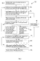
Figure 2 is a flow chart of a method of generating summarised network topology parameters of a communications network domain comprising a plurality of network nodes and a plurality of interconnecting links according to a first embodiment of the invention; -
Figure 3(a) is a diagrammatic representation of an equivalent summarized topology of the network domain ofFigure 1(a) generated using the method of the first embodiment; -
Figure 3(b) is a diagrammatic representation of an equivalent summarized topology of the network domain ofFigure 1(b) generated using the method of the first embodiment; -
Figure 4 is a diagrammatic representation of a communications network comprising four network domains A, B, C and D; -
Figure 5 is a diagrammatic representation of the communications network ofFigure 4 following generation of network topology parameters for domains A, B and C, as seen from domain D; and -
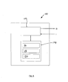
Figure 6 is a diagrammatic representation of a communications apparatus according to a second embodiment of the invention. - Referring to
Figures 1 to 3 , a first embodiment of the invention provides amethod 30 of generating summarised network topology parameters of acommunications network domain communications network domain 10 shown inFigure 1(a) comprises fivenetwork nodes links 16, each interconnectinglink 16 connecting twonodes communications network domain 20 is shown inFigure 1(b) and comprises ninenetwork nodes links 26. - Each interconnecting
link 16 has transmission parameters associated with it, which in this example comprise a label identifying the administrative colour of thelink 16, the bandwidth of the link and the traffic engineering cost of the link. This information is typically stored centrally, for example in the memory of a router or path computation engine of thenetwork domain 10. - The
method 30 identifiesnetwork nodes nodes 32, and generates summarised network topology parameters for each pair of summarized nodes 34-52. The generated summarised network topology parameters can by represented by an equivalent summarizedtopology Figures 3(a) and 3(b) , which is what thedomains nodes links nodes respective network domain nodes network node links network domain nodes links topology actual network nodes links - The method uses the Bellman-Ford algorithm which is a well known graph search algorithm which computes single source shortest-paths in a weighted directed graph (digraph) and is often used in routing. The
network domain network nodes links links - The Bellman-Ford algorithm generates a table of all available paths between two summarized
nodes network domain nodes network domain links 16, 26 (edges) comprising the path. The transmission parameters are returned from the central store of transmission parameters. The algorithm is then "relaxed", i.e. repeated/iterated, to thereby identify a second, different path between the summarizednodes domain nodes - The summarised network topology parameters are created as follows for each pair of summarized
nodes nodes node nodes network nodes domain intermediate network node path 38. The transmission parameter information includes the cumulative administrative cost (label) or traffic engineering (TE) cost (label) of the path, the administrative colour of the path (or of each of the interconnecting links in the path), and the bandwidth of the path, which is set to the bandwidth of the lowest bandwidth link in the path. The transmission parameter information may also include one or more of optical signal to noise ratio (OSNR), polarization mode dispersion (PMD) and nonlinear phase shift (NLPS). - The transmission parameters relating to each identified path are centrally stored in random access memory (RAM) accessible by the alogorithm and associated with the target summarized
node paths 40, in order to determine if any of the technology specific transmission parameters which would allow path bundling, such as administrative colour, matches that of a previously determined path 42. If a match is found, the bandwidth of the current path is bundled with the bandwidth of the previously determined path, to generate a bundled path, and the administrative cost of the bundled path is set to the lower of the administrative cost of the previously determined path and the current path 42. If a match is not found 44, the current path is stored separately. - Bundling is a process that alters the representation of a group of resources. From a group of N resources which share a common parameter, such as administrative colour, one can obtain a single resource with similiar parameters. The advantage of this approach is it reduces the amount of data needed to describe a set of resources. For example, if there are two different possible paths between two nodes, that have the same administrative colour, the paths can summarized ("bundled") into a single path having a bandwidth equal to the sum of the bandwidths of the two paths, with the same colour. Where the TE costs are different, the TE cost of the summarized resource can be set to the lower/higher of the two TE costs, or their average, as desired.
- After applying the Bellman-Ford algorithm, the target summarized node has a table comprising a number of paths between the source and target summarized nodes, each path having associated transmission parameters. The transmission parameters are then reviewed to determine whether the bandwidths obtained for the paths can be implemented, as will be described in more detail below. The resulting, potentially modified, transmission parameters become the summarised network topology parameters for the selected summarized
nodes 50. - Where there are more than two summarized
nodes 22 in thenetwork domain 20, as inFigure 1(b) , a second pair of summarized nodes is selected and the above process repeated for that pair of summarized nodes. The selection of pairs of summarized nodes is repeated until summarised network topology parameters have been created for each pair of summarized nodes 52. - The summarised network topology parameters for each pair of summarized nodes 52 are stored in memory and transmitted to other entities.
- In more detail, the Bellman-Ford algorithm is applied as follows, in respect of the
network topology 10 ofFigure 1(a) . In this example, the application of the algorithm has been partially simplified compared to a standard Bellman-Ford algorithm because none of the interconnecting links have a negative weight, since both administrative cost and TE cost are defined as positive. Following the identification of all of the available paths by the Bellman-Ford algorithm the transmission parameters are reviewed in a path pruning step, to determine whether the available resources, such as bandwidth, within the network domain (provided as network resource parameters) allow the bandwidths of the paths to be implemented.
 procedure TE_aggregation_BellmanFord(router_list, link_list, initial router,
 end_router)
  // The input parameters are:
  // - the list of network nodes ("routers") in the network domain to be summarized
  // - the list of all network links of the network domain
  // - a source summarized node
 {
  // Initialization
  for each router named NODE in router_list {
   if NODE is initial_router then NODE.paths = path_with_no_cost_and_full
 resources
   else NODE.paths = empty list
 }
   for i from 1 to number_of_elements(link_list)-1 { // "cycle 1"
   for each link named S-Dx in link_list {
     // link S-Dx is a link between node S(ource) to node D(estination)
     // node D(estination) is the target node
     node Source = S-Dx.source
     node Destination = S-Dx.destination
     for each PATH on Source {
        if PATH does not include link S-Dx and does not pass from node Destination
 (to avoid loops) {
          D.available_paths = D.available_paths + PATH merged to S-Dx:
   }
  }
 For each PATH in end_router.paths, starting with lower cost paths, compute the
 restrictions and evaluate if there is any over-allocation of resources and in case
 delete/reduce the needed path.
 }
- AB (50, 4, 2)
- AC (10, 10, 3)
- CB (80, 5, 2)
- CD1 (20, 3, 3)
- CD2 (20, 3, 2)
- CE (30, 2, 3)
- DE (30, 7, 3)
- EB (10, 5, 3)
- AB, AC, CB, CD1, CD2, CE, DE, EB.
- Looking at link AB:
- We find Path AB that goes from A to B (50,4,2)
- Looking at link AC:
- We find Path AC that goes from A to C (10,10,3)
- Looking at link CB:
- We find no extra path for B because link CB cannot be merged to Path
- AC (they have different administrative Colours)
- Looking at link CD1:
- We find Path AC-CD1 that goes from A to D (30,3,3) ->
TheTEM 30 is 10 + 20 (TE cost is added)
The Bandwidth is 3 because that is the maximum that can be allocated on all links (AC has a Bandwidth of 10 and CD1 has a Bandwidth of 3, and the Bandwidth of the Path must be set to the lowest Bandwidth of the links)
The colour is 3 because it is the same on both links
- We find Path AC-CD1 that goes from A to D (30,3,3) ->
- Looking at link CD2:
- We find no extra path for D because link CD2 cannot be merged to Path AC (they have different administrative Colours)
- Looking at link CE:
- We find Path AC-CE that goes from A to E (40,2,3) -> The
TEM 40 is 10 + 30 (TE cost is added) - The Bandwidth is 2 because that is the maximum that can be allocated on all links (AC has a Bandwidth of 10 and CE has a Bandwidth of 2)
- The colour is 3 because it is the same on both links
- We find Path AC-CE that goes from A to E (40,2,3) -> The
- Looking at link DE:
- We find Path AC-CD1-DE that goes from A to E (60,3,3) ->
TheTEM 60 is 30 + 30 (TE cost is added)
The Bandwidth is 3 because that is the maximum that can be allocated on all links (the links have Bandwidths of 10, 3 and 3 respectively)
The colour is 3 because it is the same on all links
- We find Path AC-CD1-DE that goes from A to E (60,3,3) ->
- Looking at link EB:
- We find Path AC-CD1-DE-EB that goes from A to B (70,3,3) -> The
TEM 70 is 60 + 10 (TE cost is added)
The Bandwidth is 3 because that is the maximum that can be allocated on all links (the links have Bandwidths of 10, 3, 3 and 3 respectively)
The colour is 3 because it is the same on all links - We find Path AC-CE-EB that goes from A to B (50,2,3) ->
TheTEM 50 is 40 + 10 (TE cost is added)
The Bandwidth is 2 because that is the maximum that can be allocated on all links (the links have Bandwidths of 10, 2 and 3 respectively, and the Bandwidth for the path must be set to the lowest value)
The colour is 3 because it is the same on all links
- We find Path AC-CD1-DE-EB that goes from A to B (70,3,3) -> The
- Path AB that goes from A to B (50,4,2)
- Path AC-CE-EB that goes from A to B (50,2,3)
- Path AC-CD1-DE-EB that goes from A to B (70,3,3)
- AB can be setup and consumes all the bandwidth on link AB
- AC-CE-EB can be setup and consumes a bandwidth of 2 on links AC-CE-EB
- AC-CD1-DE-EB cannot be setup because the network resource parameters indicate that link AC only has a remaining free bandwidth of 1. So we must change
- Path AC-CD1-DE-EB that goes from A to B (70,3,3) having a Bandwidth of 3
- To
- Path AC-CD1-DE-EB that goes from A to B (70,1,3) having a Bandwidth of 1, since the maximum available Bandwidth that we can allocate is 1.
- Path AB that goes from A to B (50,4,2)
- Path AC-CE-EB that goes from A to B (50,2,3)
- Path AC-CD1-DE-EB that goes from A to B (70,1,3)
Claims (11)
- A method of generating summarised network topology parameters of a communications network domain comprising a plurality of network nodes (12, 14, 16) and a plurality of interconnecting network domain paths, the method comprising:identifying a plurality of network nodes configured to interface with one or more other network domains as summarized nodes (12);identifying each available network domain path between each pair of the summarized nodes within the network domain, at least one said network domain path between each said pair of summarized nodes comprising at least one other network node and respective interconnecting links;and generating summarised network topology parameters for each said pair of summarized nodes, each summarised network topology parameter being dependent on a respective transmission parameter of the said available network domain paths;wherein, where there are a plurality of available network domain paths between a said pair of summarized nodes, the method further comprises the steps of:determining whether a transmission parameter of a first said path would allow the path to be bundled with another said path;comparing any such transmission parameter with the or each transmission parameter of any previously determined paths to determine whether there exists a previously determined path which has a matching transmission parameter;and, if a matching transmission parameter is found, adding the bandwidth of the first path to the bandwidth of the said other path to form a bundled path andcomparing the bandwidth of each interconnecting link of the bundled path with a maximum available bandwidth of said interconnecting link, and if the bandwidth of said interconnecting link is greater than its maximum available bandwidth,reducing a bandwidth of one of the first path and the said other path such that the bandwidth of said interconnecting link is not greater than its maximum available bandwidth;wherein the method further comprises advertising said summarised network topology parameters to another network domain.
- A method as claimed in claim 1, wherein the method comprises identifying the or each available network domain path and generating summarised network topology parameters for a said pair of summarized nodes by applying the Bellman-Ford algorithm.
- A method as claimed in claim 2, wherein the Bellman-Ford algorithm performs a number of relaxation steps dependent on the number of network nodes.
- A method as claimed in claim 3, wherein the method comprises generating the summarised network topology parameters by the Bellman-Ford algorithm returning one or more transmission parameters for the path being identified during each said relaxation step.
- A method as claimed in any preceding claim wherein a said transmission parameter comprises one of administrative colour, administrative cost, traffic engineering cost, optical signal to noise ratio (OSNR), polarization mode dispersion (PMD) and nonlinear phase shift (NLPS).
- A method as claimed in claims 4 or 5, wherein the method further comprises generating the summarised network topology parameters by comparing the said returned transmission parameters with predetermined network domain resource parameters and if a network domain resource parameter has a lower value than the respective transmission parameter, setting the transmission parameter to the network domain resource parameter value.
- A method as claimed in any preceding claim, wherein each network node within the network domain is provided with a transport network assigned address, the transport network comprising other network domains, and the method comprises at least one summarized node having the transport network assigned address of one or more of the network nodes associated with it.
- A communications apparatus for generating summarised network topology parameters of a communications network domain comprising a plurality of network nodes (12, 14, 16) and a plurality of interconnecting network domain paths, the apparatus comprising a processor and memory and being arranged to:identify a plurality of network nodes configured to interface with one or more other network domains as summarized nodes (12);identify each available network domain path between each pair of the summarized nodes within the network domain, at least one said network domain path between each said pair of summarized nodes comprising at least one other network node andrespective interconnecting links;generate summarised network topology parameters for each said pair of summarized nodes, the summarised topology parameters being dependent on the transmission parameters of one or more available paths between each said respective pair of summarized nodes, at least one said path comprising at least one other network node and respective interconnecting links;wherein, the apparatus is arranged to, where there are a plurality of available network domain paths between a said pair of summarized nodes:determine whether a transmission parameter of a first said path would allow the path to be bundled with another said path;compare any such transmission parameter with the or each transmission parameter of any previously determined paths to determine whether there exists a previously determined path which has a matching transmission parameter;and, if a matching transmission parameter is found, add the bandwidth of the first path to the bandwidth of the said other path to form a bundled path and compare the bandwidth of each interconnecting link of the bundled path with a maximum available bandwidth of said interconnecting link, and if the bandwidth of said interconnecting link is greater than its maximum available bandwidth, reduce a bandwidth of one of the first path and the said other path such that the bandwidth of said interconnecting link is not greater than its maximum available bandwidth; the apparatus further arranged to advertise said summarised network topology parameters to another network domain.
- A communications apparatus as claimed in claim 8, wherein the summarised network topology parameters are dependent on the corresponding transmission parameters of the said one or more available paths.
- A communications apparatus as claimed in claims 8 or 9, wherein the communications monitoring apparatus comprises one of a path computation element, a router controller, and a network node.
- A computer programme product comprising programme code for performing the steps of the method of generating summarised network topology parameters of a communications network domain comprising a plurality of network nodes and a plurality of interconnecting links as claimed in any of claims 1 to 7.
Applications Claiming Priority (1)
| Application Number | Priority Date | Filing Date | Title |
|---|---|---|---|
| PCT/EP2008/066738 WO2010063321A1 (en) | 2008-12-03 | 2008-12-03 | Generating network topology parameters and monitoring a communications network domain |
Publications (2)
| Publication Number | Publication Date |
|---|---|
| EP2371094A1 EP2371094A1 (en) | 2011-10-05 |
| EP2371094B1 true EP2371094B1 (en) | 2015-02-18 |
Family
ID=40786534
Family Applications (1)
| Application Number | Title | Priority Date | Filing Date |
|---|---|---|---|
| EP08875411.4A Not-in-force EP2371094B1 (en) | 2008-12-03 | 2008-12-03 | Method and communication apparatus for generating summarised network topology parameters |
Country Status (3)
| Country | Link |
|---|---|
| US (1) | US8711719B2 (en) |
| EP (1) | EP2371094B1 (en) |
| WO (1) | WO2010063321A1 (en) |
Families Citing this family (22)
| Publication number | Priority date | Publication date | Assignee | Title |
|---|---|---|---|---|
| US8681654B2 (en) * | 2009-10-14 | 2014-03-25 | At&T Intellectual Property I, L.P. | Methods and apparatus to design a survivable internet protocol link topology |
| US9497120B1 (en) * | 2010-03-31 | 2016-11-15 | EMC IP Holding Company, LLC | Automated top-down multi-abstraction infrastructure performance analytics-network infrastructure-as-a-service |
| EP2501065A1 (en) * | 2011-03-17 | 2012-09-19 | Telefonaktiebolaget LM Ericsson (publ) | Method and apparatus for optical path validation in an optical network |
| EP2509266A1 (en) * | 2011-04-05 | 2012-10-10 | Alcatel Lucent | Method of pooling resources of a computer network |
| US9130870B1 (en) * | 2011-04-15 | 2015-09-08 | Big Switch Networks, Inc. | Methods for determining network topologies |
| WO2013120512A1 (en) | 2012-02-14 | 2013-08-22 | Telefonaktiebolaget L M Ericsson (Publ) | Method and apparatus for routing in a multi-area communication network |
| US9118421B2 (en) * | 2012-05-16 | 2015-08-25 | Ciena Corporation | Extending control plane functions to the network edge in an optical transport network |
| US9124960B2 (en) * | 2012-05-16 | 2015-09-01 | Ciena Corporation | Intelligent and scalable routing in multi-domain optical networks |
| US9270597B2 (en) * | 2012-07-10 | 2016-02-23 | Futurewei Technologies, Inc. | Representing bandwidth constraints in partially controlled environments |
| US20140112350A1 (en) * | 2012-10-19 | 2014-04-24 | Electronics And Telecommunications Research Institute | Apparatus and method for controlling uni path |
| WO2014066252A1 (en) * | 2012-10-22 | 2014-05-01 | Huawei Technologies Co, Ltd. | Linked identifiers for multiple domains |
| US9374285B1 (en) | 2013-02-07 | 2016-06-21 | Big Switch Networks, Inc. | Systems and methods for determining network topologies |
| CN103780515B (en) * | 2014-02-12 | 2017-02-08 | 华为技术有限公司 | Method and controller for announcing bandwidth of cluster system |
| US10298517B2 (en) * | 2014-02-17 | 2019-05-21 | Telefonaktiebolaget Lm Ericsson (Publ) | Method and apparatus for allocating physical resources to a summarized resource |
| JP6443925B2 (en) * | 2015-03-20 | 2018-12-26 | 日本電気株式会社 | Control device, communication system, control method, and program |
| US10560367B2 (en) * | 2016-01-18 | 2020-02-11 | Nokia Of America Corporation | Bidirectional constrained path search |
| US10594564B2 (en) * | 2016-10-31 | 2020-03-17 | International Business Machines Corporation | Network topology-preserving internet protocol address anonymization |
| EP3815339A1 (en) * | 2018-07-24 | 2021-05-05 | Huawei Technologies Co., Ltd. | Edge computing topology information exposure |
| US11178067B2 (en) * | 2019-10-07 | 2021-11-16 | Cisco Technology, Inc. | Service allocation across multi-managed heterogeneous networks |
| CN113630274A (en) * | 2021-08-12 | 2021-11-09 | 中电积至(海南)信息技术有限公司 | Transmission path visual representation method of software defined anonymous communication network |
| CN113868813B (en) * | 2021-09-13 | 2022-06-03 | 广东工业大学 | Performance evaluation method of power information system, electronic device and storage medium |
| CN114844784B (en) * | 2022-04-11 | 2023-08-08 | 桂林电子科技大学 | Topology modeling method of reconfigurable scanning network |
Family Cites Families (6)
| Publication number | Priority date | Publication date | Assignee | Title |
|---|---|---|---|---|
| US7042846B2 (en) * | 2000-01-27 | 2006-05-09 | International Business Machines Corporation | Restrictive costs in network systems |
| US6744740B2 (en) * | 2001-12-21 | 2004-06-01 | Motorola, Inc. | Network protocol for wireless devices utilizing location information |
| EP1463235B1 (en) * | 2003-03-24 | 2005-03-16 | Alcatel | OSPF monitor and monitoring process |
| US8312145B2 (en) * | 2003-12-22 | 2012-11-13 | Rockstar Consortium US L.P. | Traffic engineering and bandwidth management of bundled links |
| WO2008055539A1 (en) * | 2006-11-06 | 2008-05-15 | Telefonaktiebolaget Lm Ericsson (Publ) | Multi-domain network and method for multi-domain network |
| US8000323B2 (en) * | 2008-04-30 | 2011-08-16 | Verizon Patent And Licensing Inc. | Method and system for announcing traffic engineering parameters of composite transport groups |
-
2008
- 2008-12-03 WO PCT/EP2008/066738 patent/WO2010063321A1/en active Application Filing
- 2008-12-03 US US13/132,904 patent/US8711719B2/en active Active
- 2008-12-03 EP EP08875411.4A patent/EP2371094B1/en not_active Not-in-force
Non-Patent Citations (8)
| Title |
|---|
| "OIF-ENNI-OSPF-01.0", ITU-T DRAFT ; STUDY PERIOD 2005-2008, INTERNATIONAL TELECOMMUNICATION UNION, GENEVA ; CH, vol. Study Group 15, 17 January 2007 (2007-01-17), pages 1 - 45, XP017537299 * |
| JINGJUN ZHANG ET AL: "New QoS approximation approach for topology aggregation", TENCON 2008 - 2008, TENCON 2008. IEEE REGION 10 CONFERENCE, IEEE, PISCATAWAY, NJ, USA, 19 November 2008 (2008-11-19), pages 1 - 5, XP031414492, ISBN: 978-1-4244-2408-5, DOI: 10.1109/TENCON.2008.4766752 * |
| KOMPELLA Y REKHTER JUNIPER NETWORKS K: "Label Switched Paths (LSP) Hierarchy with Generalized Multi-Protocol Label Switching (GMPLS) Traffic Engineering (TE); rfc4206.txt", 20051001, 1 October 2005 (2005-10-01), XP015054887, ISSN: 0000-0003 * |
| KYANG TAEK CHUNG ET AL: "Performance evaluation of topology aggregation in PNNI network", TENCON 2001. PROCEEDINGS OF IEEE REGION 10 INTERNATIONAL CONFERENCE ON ELCTRICAL AND ELECTRONIC TECHNOLOGY. SINGAPORE, AUG. 19 - 22, 2001; [IEEE REGION 10 ANNUAL CONFERENCE], NEW YORK , NY : IEEE, US, vol. 1, 19 August 2001 (2001-08-19), pages 261 - 264, XP010556245, ISBN: 978-0-7803-7101-9 * |
| LEE W C: "TOPOLOGY AGGREGATION FOR HIERARCHICAL ROUTING IN ATM NETWORKS", COMPUTER COMMUNICATION REVIEW, ACM, NEW YORK, NY, US, vol. 25, no. 2, 1 April 1995 (1995-04-01), pages 82 - 92, XP000570739, ISSN: 0146-4833, DOI: 10.1145/210613.210625 * |
| SULEYMAN ULUDAG ET AL: "Analysis of Topology Aggregation techniques for QoS routing", ACM COMPUTING SURVEYS, vol. 39, no. 3, 3 September 2007 (2007-09-03), pages 7 - es, XP055031194, ISSN: 0360-0300, DOI: 10.1145/1267070.1267071 * |
| WHAY CHIOU LEE: "Minimum equivalent subspanner algorithms for topology aggregation in ATM networks", ATM, 1999. ICATM '99. 1999 2ND INTERNATIONAL CONFERENCE ON COLMAR, FRANCE 21-23 JUNE 1999, PISCATAWAY, NJ, USA,IEEE, US, 21 June 1999 (1999-06-21), pages 351 - 359, XP010346209, ISBN: 978-0-7803-5428-9 * |
| XIAOMIN CHEN ET AL: "Multipath routing with topology aggregation for scalable inter-domain service provisioning in optical networks", OPTICAL SWITCHING AND NETWORKING, ELSEVIER, NL, vol. 9, no. 4, 26 January 2012 (2012-01-26), pages 314 - 322, XP028398934, ISSN: 1573-4277, [retrieved on 20120516], DOI: 10.1016/J.OSN.2012.01.002 * |
Also Published As
| Publication number | Publication date |
|---|---|
| EP2371094A1 (en) | 2011-10-05 |
| WO2010063321A1 (en) | 2010-06-10 |
| US8711719B2 (en) | 2014-04-29 |
| US20110292832A1 (en) | 2011-12-01 |
Similar Documents
| Publication | Publication Date | Title |
|---|---|---|
| EP2371094B1 (en) | Method and communication apparatus for generating summarised network topology parameters | |
| US8611232B2 (en) | Method of simple and efficient failure resilient load balancing | |
| US7889675B2 (en) | Method and system for multi-layer network routing | |
| CN105743794B (en) | Management apparatus and management method for multi-layer network | |
| Ramamurthy et al. | Capacity performance of dynamic provisioning in optical networks | |
| Chowdhury et al. | Dedicated protection for survivable virtual network embedding | |
| US7113481B2 (en) | Informed dynamic path protection for optical networks | |
| EP2685685B1 (en) | Method and related apparatus for establishing link-diverse traffic paths in a telecommunications network | |
| US7382738B2 (en) | Method and apparatus for computing metric information for abstracted network links | |
| US7366112B2 (en) | Communication network control system, control method, node and program | |
| KR101674177B1 (en) | Transport Software-Defined Network controller of providing E-LAN between multi-nodes and method thereof | |
| Shahriar et al. | Virtual network embedding with guaranteed connectivity under multiple substrate link failures | |
| Shahriar et al. | Connectivity-aware virtual network embedding | |
| Yoo et al. | Adaptive routing considering the number of available wavelengths in WDM networks | |
| Bhatia et al. | Bandwidth guaranteed routing with fast restoration against link and node failures | |
| US6731608B2 (en) | Complex node representations in PNNI systems | |
| Maier et al. | Multi-domain routing techniques with topology aggregation in ASON networks | |
| Segovia et al. | Availability analysis of GMPLS connections based on physical network topology | |
| Karasan et al. | Robust path design algorithms for traffic engineering with restoration in MPLS networks | |
| Duelli et al. | Greedy design of resilient multi-layer networks | |
| Singh et al. | Minimum connection count wavelength assignment strategy for WDM optical networks | |
| Saad et al. | Inter-domain wavelength routing in optical WDM networks | |
| Cohen et al. | Proactive rerouting in network overlays | |
| Jaekel et al. | Strategies for traffic grooming over logical topologies | |
| Vlachos et al. | A service-transparent and self-organized optical network architecture |
Legal Events
| Date | Code | Title | Description |
|---|---|---|---|
| PUAI | Public reference made under article 153(3) epc to a published international application that has entered the european phase |
Free format text: ORIGINAL CODE: 0009012 |
|
| 17P | Request for examination filed |
Effective date: 20110511 |
|
| AK | Designated contracting states |
Kind code of ref document: A1 Designated state(s): AT BE BG CH CY CZ DE DK EE ES FI FR GB GR HR HU IE IS IT LI LT LU LV MC MT NL NO PL PT RO SE SI SK TR |
|
| DAX | Request for extension of the european patent (deleted) | ||
| 17Q | First examination report despatched |
Effective date: 20120913 |
|
| REG | Reference to a national code |
Ref country code: DE Ref legal event code: R079 Ref document number: 602008036725 Country of ref document: DE Free format text: PREVIOUS MAIN CLASS: H04L0012560000 Ipc: H04L0012280000 |
|
| GRAP | Despatch of communication of intention to grant a patent |
Free format text: ORIGINAL CODE: EPIDOSNIGR1 |
|
| INTG | Intention to grant announced |
Effective date: 20140708 |
|
| RIC1 | Information provided on ipc code assigned before grant |
Ipc: H04L 12/751 20130101ALI20140627BHEP Ipc: H04L 12/725 20130101ALI20140627BHEP Ipc: H04L 12/28 20060101AFI20140627BHEP Ipc: H04L 12/40 20060101ALI20140627BHEP Ipc: H04L 12/24 20060101ALI20140627BHEP Ipc: H04L 12/759 20130101ALI20140627BHEP Ipc: H04L 12/709 20130101ALI20140627BHEP Ipc: H04L 12/707 20130101ALI20140627BHEP Ipc: H04L 12/715 20130101ALI20140627BHEP |
|
| GRAS | Grant fee paid |
Free format text: ORIGINAL CODE: EPIDOSNIGR3 |
|
| GRAA | (expected) grant |
Free format text: ORIGINAL CODE: 0009210 |
|
| AK | Designated contracting states |
Kind code of ref document: B1 Designated state(s): AT BE BG CH CY CZ DE DK EE ES FI FR GB GR HR HU IE IS IT LI LT LU LV MC MT NL NO PL PT RO SE SI SK TR |
|
| REG | Reference to a national code |
Ref country code: GB Ref legal event code: FG4D |
|
| REG | Reference to a national code |
Ref country code: CH Ref legal event code: EP |
|
| REG | Reference to a national code |
Ref country code: AT Ref legal event code: REF Ref document number: 711035 Country of ref document: AT Kind code of ref document: T Effective date: 20150315 |
|
| REG | Reference to a national code |
Ref country code: IE Ref legal event code: FG4D |
|
| REG | Reference to a national code |
Ref country code: DE Ref legal event code: R096 Ref document number: 602008036725 Country of ref document: DE Effective date: 20150326 |
|
| REG | Reference to a national code |
Ref country code: NL Ref legal event code: VDEP Effective date: 20150218 |
|
| REG | Reference to a national code |
Ref country code: AT Ref legal event code: MK05 Ref document number: 711035 Country of ref document: AT Kind code of ref document: T Effective date: 20150218 |
|
| REG | Reference to a national code |
Ref country code: LT Ref legal event code: MG4D |
|
| PG25 | Lapsed in a contracting state [announced via postgrant information from national office to epo] |
Ref country code: SE Free format text: LAPSE BECAUSE OF FAILURE TO SUBMIT A TRANSLATION OF THE DESCRIPTION OR TO PAY THE FEE WITHIN THE PRESCRIBED TIME-LIMIT Effective date: 20150218 Ref country code: LT Free format text: LAPSE BECAUSE OF FAILURE TO SUBMIT A TRANSLATION OF THE DESCRIPTION OR TO PAY THE FEE WITHIN THE PRESCRIBED TIME-LIMIT Effective date: 20150218 Ref country code: ES Free format text: LAPSE BECAUSE OF FAILURE TO SUBMIT A TRANSLATION OF THE DESCRIPTION OR TO PAY THE FEE WITHIN THE PRESCRIBED TIME-LIMIT Effective date: 20150218 Ref country code: FI Free format text: LAPSE BECAUSE OF FAILURE TO SUBMIT A TRANSLATION OF THE DESCRIPTION OR TO PAY THE FEE WITHIN THE PRESCRIBED TIME-LIMIT Effective date: 20150218 Ref country code: HR Free format text: LAPSE BECAUSE OF FAILURE TO SUBMIT A TRANSLATION OF THE DESCRIPTION OR TO PAY THE FEE WITHIN THE PRESCRIBED TIME-LIMIT Effective date: 20150218 Ref country code: NO Free format text: LAPSE BECAUSE OF FAILURE TO SUBMIT A TRANSLATION OF THE DESCRIPTION OR TO PAY THE FEE WITHIN THE PRESCRIBED TIME-LIMIT Effective date: 20150518 |
|
| PG25 | Lapsed in a contracting state [announced via postgrant information from national office to epo] |
Ref country code: AT Free format text: LAPSE BECAUSE OF FAILURE TO SUBMIT A TRANSLATION OF THE DESCRIPTION OR TO PAY THE FEE WITHIN THE PRESCRIBED TIME-LIMIT Effective date: 20150218 Ref country code: LV Free format text: LAPSE BECAUSE OF FAILURE TO SUBMIT A TRANSLATION OF THE DESCRIPTION OR TO PAY THE FEE WITHIN THE PRESCRIBED TIME-LIMIT Effective date: 20150218 Ref country code: IS Free format text: LAPSE BECAUSE OF FAILURE TO SUBMIT A TRANSLATION OF THE DESCRIPTION OR TO PAY THE FEE WITHIN THE PRESCRIBED TIME-LIMIT Effective date: 20150618 Ref country code: NL Free format text: LAPSE BECAUSE OF FAILURE TO SUBMIT A TRANSLATION OF THE DESCRIPTION OR TO PAY THE FEE WITHIN THE PRESCRIBED TIME-LIMIT Effective date: 20150218 Ref country code: GR Free format text: LAPSE BECAUSE OF FAILURE TO SUBMIT A TRANSLATION OF THE DESCRIPTION OR TO PAY THE FEE WITHIN THE PRESCRIBED TIME-LIMIT Effective date: 20150519 |
|
| PG25 | Lapsed in a contracting state [announced via postgrant information from national office to epo] |
Ref country code: SK Free format text: LAPSE BECAUSE OF FAILURE TO SUBMIT A TRANSLATION OF THE DESCRIPTION OR TO PAY THE FEE WITHIN THE PRESCRIBED TIME-LIMIT Effective date: 20150218 Ref country code: EE Free format text: LAPSE BECAUSE OF FAILURE TO SUBMIT A TRANSLATION OF THE DESCRIPTION OR TO PAY THE FEE WITHIN THE PRESCRIBED TIME-LIMIT Effective date: 20150218 Ref country code: DK Free format text: LAPSE BECAUSE OF FAILURE TO SUBMIT A TRANSLATION OF THE DESCRIPTION OR TO PAY THE FEE WITHIN THE PRESCRIBED TIME-LIMIT Effective date: 20150218 Ref country code: RO Free format text: LAPSE BECAUSE OF FAILURE TO SUBMIT A TRANSLATION OF THE DESCRIPTION OR TO PAY THE FEE WITHIN THE PRESCRIBED TIME-LIMIT Effective date: 20150218 Ref country code: CZ Free format text: LAPSE BECAUSE OF FAILURE TO SUBMIT A TRANSLATION OF THE DESCRIPTION OR TO PAY THE FEE WITHIN THE PRESCRIBED TIME-LIMIT Effective date: 20150218 |
|
| REG | Reference to a national code |
Ref country code: DE Ref legal event code: R097 Ref document number: 602008036725 Country of ref document: DE |
|
| PG25 | Lapsed in a contracting state [announced via postgrant information from national office to epo] |
Ref country code: PL Free format text: LAPSE BECAUSE OF FAILURE TO SUBMIT A TRANSLATION OF THE DESCRIPTION OR TO PAY THE FEE WITHIN THE PRESCRIBED TIME-LIMIT Effective date: 20150218 |
|
| PLBE | No opposition filed within time limit |
Free format text: ORIGINAL CODE: 0009261 |
|
| STAA | Information on the status of an ep patent application or granted ep patent |
Free format text: STATUS: NO OPPOSITION FILED WITHIN TIME LIMIT |
|
| PG25 | Lapsed in a contracting state [announced via postgrant information from national office to epo] |
Ref country code: IT Free format text: LAPSE BECAUSE OF FAILURE TO SUBMIT A TRANSLATION OF THE DESCRIPTION OR TO PAY THE FEE WITHIN THE PRESCRIBED TIME-LIMIT Effective date: 20150218 |
|
| 26N | No opposition filed |
Effective date: 20151119 |
|
| PG25 | Lapsed in a contracting state [announced via postgrant information from national office to epo] |
Ref country code: SI Free format text: LAPSE BECAUSE OF FAILURE TO SUBMIT A TRANSLATION OF THE DESCRIPTION OR TO PAY THE FEE WITHIN THE PRESCRIBED TIME-LIMIT Effective date: 20150218 |
|
| PG25 | Lapsed in a contracting state [announced via postgrant information from national office to epo] |
Ref country code: BE Free format text: LAPSE BECAUSE OF FAILURE TO SUBMIT A TRANSLATION OF THE DESCRIPTION OR TO PAY THE FEE WITHIN THE PRESCRIBED TIME-LIMIT Effective date: 20150218 |
|
| PG25 | Lapsed in a contracting state [announced via postgrant information from national office to epo] |
Ref country code: MC Free format text: LAPSE BECAUSE OF FAILURE TO SUBMIT A TRANSLATION OF THE DESCRIPTION OR TO PAY THE FEE WITHIN THE PRESCRIBED TIME-LIMIT Effective date: 20150218 Ref country code: LU Free format text: LAPSE BECAUSE OF FAILURE TO SUBMIT A TRANSLATION OF THE DESCRIPTION OR TO PAY THE FEE WITHIN THE PRESCRIBED TIME-LIMIT Effective date: 20151203 |
|
| REG | Reference to a national code |
Ref country code: CH Ref legal event code: PL |
|
| REG | Reference to a national code |
Ref country code: IE Ref legal event code: MM4A |
|
| REG | Reference to a national code |
Ref country code: FR Ref legal event code: ST Effective date: 20160831 |
|
| PG25 | Lapsed in a contracting state [announced via postgrant information from national office to epo] |
Ref country code: IE Free format text: LAPSE BECAUSE OF NON-PAYMENT OF DUE FEES Effective date: 20151203 Ref country code: LI Free format text: LAPSE BECAUSE OF NON-PAYMENT OF DUE FEES Effective date: 20151231 Ref country code: CH Free format text: LAPSE BECAUSE OF NON-PAYMENT OF DUE FEES Effective date: 20151231 |
|
| PG25 | Lapsed in a contracting state [announced via postgrant information from national office to epo] |
Ref country code: FR Free format text: LAPSE BECAUSE OF NON-PAYMENT OF DUE FEES Effective date: 20151231 |
|
| PG25 | Lapsed in a contracting state [announced via postgrant information from national office to epo] |
Ref country code: HU Free format text: LAPSE BECAUSE OF FAILURE TO SUBMIT A TRANSLATION OF THE DESCRIPTION OR TO PAY THE FEE WITHIN THE PRESCRIBED TIME-LIMIT; INVALID AB INITIO Effective date: 20081203 Ref country code: BG Free format text: LAPSE BECAUSE OF FAILURE TO SUBMIT A TRANSLATION OF THE DESCRIPTION OR TO PAY THE FEE WITHIN THE PRESCRIBED TIME-LIMIT Effective date: 20150218 |
|
| PG25 | Lapsed in a contracting state [announced via postgrant information from national office to epo] |
Ref country code: CY Free format text: LAPSE BECAUSE OF FAILURE TO SUBMIT A TRANSLATION OF THE DESCRIPTION OR TO PAY THE FEE WITHIN THE PRESCRIBED TIME-LIMIT Effective date: 20150218 |
|
| PG25 | Lapsed in a contracting state [announced via postgrant information from national office to epo] |
Ref country code: MT Free format text: LAPSE BECAUSE OF FAILURE TO SUBMIT A TRANSLATION OF THE DESCRIPTION OR TO PAY THE FEE WITHIN THE PRESCRIBED TIME-LIMIT Effective date: 20150218 Ref country code: TR Free format text: LAPSE BECAUSE OF FAILURE TO SUBMIT A TRANSLATION OF THE DESCRIPTION OR TO PAY THE FEE WITHIN THE PRESCRIBED TIME-LIMIT Effective date: 20150218 |
|
| PG25 | Lapsed in a contracting state [announced via postgrant information from national office to epo] |
Ref country code: PT Free format text: LAPSE BECAUSE OF FAILURE TO SUBMIT A TRANSLATION OF THE DESCRIPTION OR TO PAY THE FEE WITHIN THE PRESCRIBED TIME-LIMIT Effective date: 20150218 |
|
| PGFP | Annual fee paid to national office [announced via postgrant information from national office to epo] |
Ref country code: GB Payment date: 20181227 Year of fee payment: 11 |
|
| PGFP | Annual fee paid to national office [announced via postgrant information from national office to epo] |
Ref country code: DE Payment date: 20181231 Year of fee payment: 11 |
|
| REG | Reference to a national code |
Ref country code: DE Ref legal event code: R119 Ref document number: 602008036725 Country of ref document: DE |
|
| GBPC | Gb: european patent ceased through non-payment of renewal fee |
Effective date: 20191203 |
|
| PG25 | Lapsed in a contracting state [announced via postgrant information from national office to epo] |
Ref country code: GB Free format text: LAPSE BECAUSE OF NON-PAYMENT OF DUE FEES Effective date: 20191203 Ref country code: DE Free format text: LAPSE BECAUSE OF NON-PAYMENT OF DUE FEES Effective date: 20200701 |