EP2337163A1 - Connector, electronic apparatus, method for removing connector - Google Patents
Connector, electronic apparatus, method for removing connector Download PDFInfo
- Publication number
- EP2337163A1 EP2337163A1 EP08877142A EP08877142A EP2337163A1 EP 2337163 A1 EP2337163 A1 EP 2337163A1 EP 08877142 A EP08877142 A EP 08877142A EP 08877142 A EP08877142 A EP 08877142A EP 2337163 A1 EP2337163 A1 EP 2337163A1
- Authority
- EP
- European Patent Office
- Prior art keywords
- connector
- locking lever
- protrusion
- frame
- connecting terminal
- Prior art date
- Legal status (The legal status is an assumption and is not a legal conclusion. Google has not performed a legal analysis and makes no representation as to the accuracy of the status listed.)
- Granted
Links
Images









Classifications
-
- H—ELECTRICITY
- H01—ELECTRIC ELEMENTS
- H01R—ELECTRICALLY-CONDUCTIVE CONNECTIONS; STRUCTURAL ASSOCIATIONS OF A PLURALITY OF MUTUALLY-INSULATED ELECTRICAL CONNECTING ELEMENTS; COUPLING DEVICES; CURRENT COLLECTORS
- H01R24/00—Two-part coupling devices, or either of their cooperating parts, characterised by their overall structure
- H01R24/58—Contacts spaced along longitudinal axis of engagement
-
- H—ELECTRICITY
- H01—ELECTRIC ELEMENTS
- H01R—ELECTRICALLY-CONDUCTIVE CONNECTIONS; STRUCTURAL ASSOCIATIONS OF A PLURALITY OF MUTUALLY-INSULATED ELECTRICAL CONNECTING ELEMENTS; COUPLING DEVICES; CURRENT COLLECTORS
- H01R13/00—Details of coupling devices of the kinds covered by groups H01R12/70 or H01R24/00 - H01R33/00
- H01R13/62—Means for facilitating engagement or disengagement of coupling parts or for holding them in engagement
- H01R13/627—Snap or like fastening
- H01R13/6271—Latching means integral with the housing
- H01R13/6272—Latching means integral with the housing comprising a single latching arm
-
- H—ELECTRICITY
- H01—ELECTRIC ELEMENTS
- H01R—ELECTRICALLY-CONDUCTIVE CONNECTIONS; STRUCTURAL ASSOCIATIONS OF A PLURALITY OF MUTUALLY-INSULATED ELECTRICAL CONNECTING ELEMENTS; COUPLING DEVICES; CURRENT COLLECTORS
- H01R13/00—Details of coupling devices of the kinds covered by groups H01R12/70 or H01R24/00 - H01R33/00
- H01R13/62—Means for facilitating engagement or disengagement of coupling parts or for holding them in engagement
- H01R13/629—Additional means for facilitating engagement or disengagement of coupling parts, e.g. aligning or guiding means, levers, gas pressure electrical locking indicators, manufacturing tolerances
- H01R13/633—Additional means for facilitating engagement or disengagement of coupling parts, e.g. aligning or guiding means, levers, gas pressure electrical locking indicators, manufacturing tolerances for disengagement only
-
- H—ELECTRICITY
- H01—ELECTRIC ELEMENTS
- H01R—ELECTRICALLY-CONDUCTIVE CONNECTIONS; STRUCTURAL ASSOCIATIONS OF A PLURALITY OF MUTUALLY-INSULATED ELECTRICAL CONNECTING ELEMENTS; COUPLING DEVICES; CURRENT COLLECTORS
- H01R24/00—Two-part coupling devices, or either of their cooperating parts, characterised by their overall structure
- H01R24/60—Contacts spaced along planar side wall transverse to longitudinal axis of engagement
- H01R24/62—Sliding engagements with one side only, e.g. modular jack coupling devices
- H01R24/64—Sliding engagements with one side only, e.g. modular jack coupling devices for high frequency, e.g. RJ 45
Definitions
- the embodiments discussed herein are related to a connecting unit, an electronic device, and a connector unplugging method that make it easier to unplug a LAN (Local Area Network) cable from a PCI (Peripheral Component Interconnect) card.
- LAN Local Area Network
- PCI Peripheral Component Interconnect
- PCI hot-swap cassettes (or cartridges) are becoming widely used as a hot-swapping technology for PCI cards.
- a PCI card is placed in a PCI hot-swap cassette and the PCI hot-swap cassette is mounted in a computer or an information processing apparatus.
- a front plate of the PCI card is recessed from the surface of the computer.
- the recess is generally very narrow as illustrated in FIG. 22(b) and it is difficult to unplug a LAN cable connected to the PCI card with fingers. Therefore, to unplug the LAN cable for maintenance, it is necessary to press down a release clip (or lever) for unlocking a LAN connector of the LAN cable with a tool such as a flat-head screwdriver.
- FIG. 23 illustrates a related-art LAN cable connected to a PCI card. As is apparent from FIG. 23 , the release clip is short and it is difficult to unlock the LAN connector only with fingers.
- a related-art document discloses an actuator that makes it easier to put a plug in and out of a socket.
- Another related-art document discloses a modular plug having a lever for unlocking the modular plug to pull out the modular plug from a connector.
- the disclosed technology makes it easier to pull out the modular plug from the connector and also makes it possible to reduce the size and thickness of the connector.
- Another related-art document discloses a connector with an attaching/detaching mechanism that makes it possible to reduce the size of the connector and to improve the reliability and operability of the connector. Still another related-art document discloses a plug connecting part including a sliding sleeve that is operated to move a locking part to an unlock position to unlock the plug connecting part.
- a connecting unit that includes a connector protrusion including a locking lever provided on a first surface and a first connecting terminal provided on a second surface opposing the first surface or on a front surface; a connector socket including a second connecting terminal to be connected with the first connecting terminal and a housing having a groove formed in an inner wall so that the locking lever is pressed down and slides along the groove when the connector protrusion is inserted into the connector socket; and a connector frame surrounding the connector protrusion and having an opening in a surface opposing the first surface of the connector protrusion.
- the connector frame is configured such that when the connector frame is moved in a direction opposite to the direction where the connector protrusion is inserted while the connector protrusion is in the connector socket, an end of the locking lever fits into the opening and the locking lever is unlocked.
- an electronic device including a connector socket into which a connector protrusion is to be inserted.
- the connector protrusion is surrounded by a connector frame and includes a locking lever provided on a first surface and a first connecting terminal provided on a second surface opposing the first surface or on a front surface.
- the connector socket includes a second connecting terminal to be connected with the first connecting terminal and a housing having a groove formed in an inner wall so that the locking lever is pressed down and slides along the groove when the connector protrusion is inserted into the connector socket.
- the connector frame has an opening in a surface opposing the first surface of the connector protrusion and is configured such that when the connector frame is moved in a direction opposite to the direction where the connector protrusion is inserted while the connector protrusion is in the connector socket, an end of the locking lever fits into the opening and the locking lever is unlocked.
- a method of unplugging a connector protrusion of a connecting unit from a connector socket of the connecting unit includes a locking lever provided on a first surface and a first connecting terminal provided on a second surface opposing the first surface or on a front surface.
- the connector socket includes a second connecting terminal to be connected with the first connecting terminal and a housing having a groove formed in an inner wall so that the locking lever is pressed down and slides along the groove when the connector protrusion is inserted into the connector socket.
- the connecting unit further includes a connector frame surrounding the connector protrusion and having an opening in a surface opposing the first surface of the connector protrusion. The method includes fitting an end of the locking lever into the opening of the connector frame while the connector protrusion is in the connector socket; and moving the connector frame in a direction opposite to a direction where the connector protrusion is inserted into the connector socket to unlock the locking lever.
- a connecting unit that includes a connector protrusion including a locking lever provided on a first surface and a first connecting terminal provided on a second surface opposing the first surface or on a front surface; a connector socket including a second connecting terminal to be connected with the first connecting terminal and a housing having a groove formed in an inner wall so that the locking lever is pressed down and slides along the groove when the connector protrusion is inserted into the connector socket; and a connector frame surrounding the connector protrusion.
- the connector frame is configured such that when the connector frame is pressed in a direction where the connector protrusion is inserted, an end of the locking lever slides into a space surrounded by the connector frame and the locking lever is unlocked.
- an electronic device including a connector socket into which a connector protrusion is to be inserted.
- the connector protrusion is surrounded by a connector frame and includes a locking lever provided on a first surface and a first connecting terminal provided on a second surface opposing the first surface or on a front surface.
- the connector socket includes a second connecting terminal to be connected with the first connecting terminal and a housing having a groove formed in an inner wall so that the locking lever is pressed down and slides along the groove when the connector protrusion is inserted into the connector socket.
- the connector frame is configured such that when the connector frame is pressed in a direction where the connector protrusion is inserted, an end of the locking lever slides into a space surrounded by the connector frame and the locking lever is unlocked.
- a method of unplugging a connector protrusion of a connecting unit from a connector socket of the connecting unit includes a locking lever provided on a first surface and a first connecting terminal provided on a second surface opposing the first surface or on a front surface.
- the connector socket includes a second connecting terminal to be connected with the first connecting terminal and a housing having a groove formed in an inner wall so that the locking lever is pressed down and slides along the groove when the connector protrusion is inserted into the connector socket.
- the connecting unit further includes a connector frame surrounding the connector protrusion. The method includes pressing the connector frame in a direction where the connector protrusion is inserted; and thereby causing an end of the locking lever to slide into a space surrounded by the connector frame to unlock the locking lever.
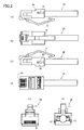
- FIG. 1 is a perspective view of a modular plug 10 for a LAN cable according to the first embodiment.
- FIGs. 2(a) through 2(f) are drawings illustrating six sides of the modular plug 10.
- FIG. 2(a) is a left side view
- FIG. 2(b) is a plan view
- FIG. 2(c) is a right side view
- FIG. 2(d) is a bottom view
- FIG. 2(e) is a front view
- FIG. 2(f) is a rear view of the modular plug 10.
- the same reference number indicates the same component.
- the modular plug 10 (connector protrusion) includes a locking lever 11, connecting terminals 12 (first connecting terminals), grooves 13, and dowel housings 14.
- One end of the locking lever 11 is fixed to a surface (first surface) of the modular plug 10.
- the other end of the locking lever 11 is bent at an acute angle to form a hook-like shape and a middle part of the locking lever 11 is bent at an obtuse angle.
- the locking lever 11 Similar to a release clip of a related-art LAN modular plug, the locking lever 11 has elasticity. When no force is applied to the locking lever 11, the locking lever 11 is in a locking position where the modular plug 10 engages (or is interlocked with) a PCI card (hereafter called a LAN board). When a downward force (toward the LAN cable) is applied to the middle part of the locking lever 11, the modular plug 10 is unlocked and released from the LAN board.
- a PCI card hereafter called a LAN board
- the connecting terminals 12 are connected with a twisted-pair cable with 8 cores (4 pairs) and used for electric communications between the modular plug 10 and the LAN board.
- the grooves 13 are U-shaped grooves. Assuming that a surface of the modular plug 10 where the connecting terminals 12 are arranged is the front surface, the grooves 13 are formed in the right and left side surfaces of the modular plug 10. An unlocking mechanism 20 described later engages and slides along the grooves 13.
- the dowel housings 14 are for housing dowels 22 of the unlocking mechanism 20 and have a cup shape that fits a dorm shape of the dowels 22.
- FIG. 3 is a perspective view of the unlocking mechanism 20 according to the first embodiment.
- FIGs. 4(a) through 4(f) are drawings illustrating six sides of the unlocking mechanism 20.
- FIG. 4(a) is a left side view
- FIG. 4(b) is a plan view
- FIG. 4(c) is a right side view
- FIG. 4(d) is a bottom view
- FIG. 4(e) is a front view
- FIG. 4(f) is a rear view of the unlocking mechanism 20.
- the same reference number indicates the same component.
- the unlocking mechanism 20 (connector frame) has a U-like shape surrounding the modular plug 10.
- the unlocking mechanism 20 includes an opening 21, the dowels 22, and engaging parts 23.
- the opening 21 is formed in a surface of the locking mechanism 20 that opposes the surface of the modular plug 10 to which the locking lever 11 is fixed.
- the hook-shaped end of the locking lever 11 is to fit into the opening 21.
- the engaging parts 23 engage the grooves 13 to allow the unlocking mechanism 20 to slide over the modular plug 10.
- the engaging parts 13 are formed by bending the ends of right-side and left-side walls of the unlocking mechanism 20 inward at 90 degrees.
- the dowels 22 limit the sliding movement of the unlocking mechanism 20 with respect to the modular plug 10.
- the dowels 22 protrude from the engaging parts 23 and have a dorm shape.
- the dowels 22 fit in the dowel housings 14 and thereby limit the sliding movement of the unlocking mechanism 20.
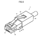
- FIG. 5 is a perspective view of a LAN connector 1 formed by fitting together the modular plug 10 and the unlocking mechanism 20.
- FIGs. 6(a) through 6(f) are drawings illustrating six sides of the LAN connector 1.
- FIG. 6(a) is a left side view
- FIG. 6(b) is a plan view
- FIG. 6(c) is a right side view
- FIG. 6(d) is a bottom view
- FIG. 6(e) is a front view
- FIG. 6(f) is a rear view of the LAN connector 1.
- the same reference number indicates the same component.
- the modular plug 10 and the unlocking mechanism 20 are fitted together to form the LAN connector 1 by engaging the grooves 13 and the engaging parts 23 and inserting the hook-shaped end of the locking lever 11 into the opening 21.
- FIGs. 7 (a) and 7(b) are a plan view and a front view of a LAN board 101.
- the LAN board 101 has a configuration similar to that of a related-art LAN board.
- the LAN board 101 includes a housing 111 and connecting terminals 112 to be connected with the connecting terminals 12 of the modular plug 10. Grooves are formed in inner walls of the housing 111. When the modular plug 10 is inserted into the housing 111, the locking lever 11 is pressed down and slides along the grooves.
- the LAN board 101 includes a communication control circuit board 120 for controlling LAN communications.
- An exemplary method of unplugging the LAN connector 1 from the LAN board 101 according to the first embodiment is described below with reference to FIG. 8 .
- the method of plugging the LAN connector 1 into the housing 111 of the LAN board 101 is similar to a related-art method and therefore its descriptions are omitted here.
- the user holds the unlocking mechanism 20 and moves or slides the unlocking mechanism 20 in an unplugging direction (the direction indicated by an arrow "a" in FIG. 8 ) along the grooves 13 engaging the engaging parts 23.
- an unplugging direction the direction indicated by an arrow "a” in FIG. 8
- the hook-shaped end of the locking lever 11 fits into the opening 21.
- the bent angle of the middle part of the locking lever 11 becomes shallower (becomes more obtuse) and the bending point of the middle part moves downward in the direction indicated by an arrow a' in FIG. 8 .
- the locking lever 11 or the LAN connector 1 is unlocked.
- the above configuration makes it possible to unlock the LAN connector 1 by just sliding the unlocking mechanism 20.
- the above configuration makes it possible to easily unplug a LAN connector from a LAN board without using a tool even when the LAN connector is located in a narrow recess.
- the dowel housings 14 and the dowels 22 function as a position fixing mechanism for keeping the unlocking mechanism 20 in a fixed position.
- the position fixing mechanism prevents the unlocking mechanism 20 from being unintentionally moved and thereby prevents the LAN connector 1 from being accidentally unplugged.
- FIG. 9 is a perspective view of an exemplary modular plug 10A according to a second embodiment.
- FIGS. 10(a) through 10(f) are drawings illustrating six sides of the modular plug 10A.
- FIG. 10(a) is a left side view
- FIG. 10 (b) is a plan view
- FIG. 10 (c) is a right side view
- FIG. 10 (d) is a bottom view
- FIG. 10 (e) is a front view
- FIG. 10(f) is a rear view of the modular plug 10A.
- the same reference number indicates the same component.
- the modular plug 10A (connector protrusion) includes a locking lever 11A, connecting terminals 12 (first connecting terminals), grooves 13, and dowel housings 14.
- the connecting terminals 12, the grooves 13, and the dowel housings 14 have substantially the same configurations and functions as those of the first embodiment and their descriptions are omitted here.
- One end of the locking lever 11A is fixed to a surface (first surface) of the modular plug 10A and a middle part of the locking lever 11A is bent at an obtuse angle.
- the other end of the locking lever 11A is a free end that is positioned near the surface of the modular plug 10A or in contact with the surface of the modular plug 10A.
- the locking lever 11A Similar to a release clip of a related-art LAN modular plug, the locking lever 11A has elasticity. When no force is applied to the locking lever 11A, the locking lever 11A is in a locking position where the modular plug 10A engages (or is interlocked with) a LAN board (e.g., the LAN board 101 of FIG. 7 ). When a downward force is applied to the middle part of the locking lever 11A, the modular plug 10A is unlocked and released from the LAN board.
- a LAN board e.g., the LAN board 101 of FIG. 7
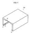
- FIG. 11 is a perspective view of an unlocking mechanism 20A according to the second embodiment.
- FIGs. 12(a) through 12(f) are drawings illustrating six sides of the unlocking mechanism 20A.
- FIG. 12(a) is a left side view
- FIG. 12(b) is a plan view
- FIG. 12(c) is a right side view
- FIG. 12(d) is a bottom view
- FIG. 12(e) is a front view
- FIG. 12(f) is a rear view of the unlocking mechanism 20A.
- the same reference number indicates the same component.
- the unlocking mechanism 20A (connector frame) has a U-shape surrounding the modular plug 10A.
- the unlocking mechanism 20A includes dowels 22, engaging parts 23, and a locking-lever sliding part 24.
- the locking-lever sliding part 24 assists a part of the locking lever 11A including at least the free end to slide into a space between the LAN cable and the unlocking mechanism 20A (or a space surrounded by the unlocking mechanism 20A) when the LAN cable is unplugged from the LAN board.
- the locking lever sliding part 24 is formed in an inner wall of the unlocking mechanism 20A that faces the surface of the modular plug 10A to which the locking lever 11A is fixed.
- the locking-lever sliding part 24 is a recess through which the locking lever 11A slides into the unlocking mechanism 20A and is a part of a wall of the unlocking mechanism 20A having a thickness that is less than the thickness of other walls.
- the locking-lever sliding part 24 increases the gap between the unlocking mechanism 20A and the LAN cable and makes it easier for the free end of the locking lever 11A to slide into the unlocking mechanism 20A.
- the dowels 22 and the engaging parts 23 have substantially the same configurations and functions as those of the first embodiment and therefore their descriptions are omitted here.
- FIG. 13 is a perspective view of a LAN connector 1A formed by fitting together the modular plug 10A and the unlocking mechanism 20A.
- FIGs. 14(a) through 14(f) are drawings illustrating six sides of the LAN connector 1A.
- FIG. 14(a) is a left side view
- FIG. 14(b) is a plan view
- FIG. 14(c) is a right side view
- FIG. 14 (d) is a bottom view
- FIG. 14 (e) is a front view
- FIG. 14(f) is a rear view of the LAN connector 1A.
- the same reference number indicates the same component.
- the modular plug 10A and the unlocking mechanism 20A are fitted together to form the LAN connector 1A by engaging the grooves 13 and the engaging parts 23.
- An exemplary method of unplugging the LAN connector 1A from the LAN board (e.g., the LAN board 101 of FIG. 7 ) according to the second embodiment is described below with reference to FIG. 15 .
- the method of plugging the LAN connector 1A into the housing 111 of the LAN board 101 is similar to a related-art method and therefore its descriptions are omitted here.
- the user holds the unlocking mechanism 20A and moves or slides the unlocking mechanism 20A toward the modular plug 10A (in the direction indicated by an arrow "b" in FIG. 15 ) along the grooves 13 engaging the engaging parts 23.
- the free end of the locking lever 11A touches the locking-lever sliding part 24 of the unlocking mechanism 20A.
- the unlocking mechanism 20A is moved further in the direction "b"
- the free end of the locking lever 11A slides into the space between the LAN cable and the inner wall of the unlocking mechanism 20A.
- the inner wall of the unlocking mechanism 20A presses the locking lever 11A in the direction "b" and causes the locking lever 11A to slide further into the unlocking mechanism 20A.
- the bent angle of the middle part of the locking lever 11A becomes shallower (becomes more obtuse) and the bending point of the middle part moves downward in the direction indicated by an arrow b' in FIG. 15 .
- the locking lever 11A or the LAN connector 1A is unlocked.
- the above configuration makes it possible to unlock the LAN connector 1A by just sliding the unlocking mechanism 20A. Accordingly, the above configuration makes it possible to easily unplug a LAN connector from a LAN board even when the LAN connector is located in a narrow recess.
- the unlocking mechanism 20A of the second embodiment may be normally separated from the modular plug 10A and attached to the modular plug 10A when unplugging the LAN connector 1A from the LAN board. With the configuration of the second embodiment, however, it is difficult to identify the position of the locking-lever sliding part 24 from the outside of the unlocking mechanism 20A when fitting together the unlocking mechanism 20A and the modular plug 10A.
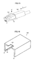
- FIG. 16 is a perspective view of an unlocking mechanism 20B according to the third embodiment.
- FIGs. 17(a) through 17(f) are drawings illustrating six sides of the unlocking mechanism 20B.
- FIG. 17(a) is a left side view
- FIG. 17(b) is a plan view
- FIG. 17(c) is a right side view
- FIG. 17(d) is a bottom view
- FIG. 17 (e) is a front view
- FIG. 17(f) is a rear view of the unlocking mechanism 20B.
- the same reference number indicates the same component.
- the unlocking mechanism 20B includes dowels 22, engaging parts 23, and a locking-lever sliding part 24A.
- the dowels 22 and the engaging parts 23 have substantially the same configurations and functions as those of the first and second embodiments and therefore their descriptions are omitted here.
- the locking-lever sliding part 24A is open to the outside via the upper surface of the unlocking mechanism 20B so that the locking-lever sliding part 24A can be identified from the outside of the unlocking mechanism 20B.
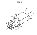
- FIG. 18 is a perspective view of a LAN connector 1B according to the third embodiment.
- the LAN connector 1B includes the modular plug 10A of the second embodiment and the unlocking mechanism 20B described above.
- the method of unplugging the LAN connector 1B is substantially the same as that of the second embodiment and therefore its descriptions are omitted here.
- one end of the locking lever 11 fits into the opening 21 of the unlocking mechanism 20 and the locking lever 11 and the unlocking mechanism 20 are thereby connected to each other.
- the unlocking mechanism 20 is moved in the unplugging direction, the locking lever 11 is unlocked and the modular plug 10 is unplugged from the LAN board.
- FIG. 19 (a) is a side view of a modular plug 10B
- FIG. 19 (b) is a plan view and a cross-sectional view of an unlocking mechanism 20C
- FIG. 19(c) is a side view of a LAN connector 1C formed by connecting the modular plug 10B and the unlocking mechanism 20C.
- the modular plug 10B includes a locking lever 11C having a spherical end 61 (see FIG. 19(a) ).
- the unlocking mechanism 20C includes an end receiving part 62 on the upper surface which is to be fitted together with the end 61 of the locking lever 11C (see FIG. 19(b) ).
- the modular plug 10B and the unlocking mechanism 20C are connected to each other by fitting the end 61 of the locking lever 11C into the end receiving part 62 of the unlocking mechanism 20C (see FIG. 19(c) ).
- the unlocking mechanism 20C is moved in an unplugging direction indicated by an arrow "a" in FIG. 19(c) , the LAN connector 1C is unlocked and released from the LAN board.
- FIG. 20 (a) is a plan view and a side view of a modular plug 10C
- FIG. 20(b) is a side view of an unlocking mechanism 20D
- FIG. 20(c) is a side view of a LAN connector 1D formed by connecting the modular plug 10C and the unlocking mechanism 20D.
- the modular plug 10C includes a locking lever 11D.
- a hole 61A to be fitted together with a spherical protrusion 62A is formed in one end of the locking lever 11D (see FIG. 20(a) ).
- the unlocking mechanism 20D includes the spherical protrusion 62A on the upper surface which is fitted into the hole 61A of the locking lever 11D (see FIG. 20(b) ).
- the modular plug 10C and the unlocking mechanism 20D are connected to each other by fitting the spherical protrusion 62A of the unlocking mechanism 20D into the hole 61A of the locking lever 11D (see FIG. 20(c) ).
- the unlocking mechanism 20D is moved in an unplugging direction indicated by an arrow "a" in FIG. 20(c) , the LAN connector 1D is unlocked and released from the LAN board.
- FIG. 21(a) is a plan view and a side view of a modular plug 10D
- FIG. 21(b) is a side view of an unlocking mechanism 20E
- FIG. 21(c) is a side view of a LAN connector 1E formed by connecting the modular plug 10D and the unlocking mechanism 20E.
- the modular plug 10D includes a locking lever 11E having an end 61B that is bent to become orthogonal to the upper surface of the modular plug 10D (see FIG. 21(a) ).
- a hole 61A as shown in FIG. 20(a) is formed in the end 61B.
- the unlocking mechanism 20E includes a connecting part 62B including a spherical protrusion 62A as shown in FIG. 20(b) and a trapezoidal support part supporting the spherical protrusion 62A in a horizontal position (see FIG. 21(b) ).
- the modular plug 10D and the unlocking mechanism 20E are connected to each other by fitting together the end 61B of the locking lever 11D and the connecting part 62B of the unlocking mechanism 20E (see FIG. 21(c) ).
- the unlocking mechanism 20E is moved in an unplugging direction indicated by an arrow "a" in FIG. 21(c) , the LAN connector 1E is unlocked and released from the LAN board.
- a connecting unit may indicate a combination of the LAN connector 1 of the first embodiment, the housing 111, and the connecting terminals 112, or a combination of the LAN connector 1A of the second embodiment, the housing 111, and the connecting terminals 112.
- a connecting unit may indicate a combination of the LAN connector 1B of the third embodiment, the housing 111, and the connecting terminals 112. Further, a connecting unit may indicate a combination of the LAN connector 1C, 1D, or 1E of the fourth embodiment, the housing 111, and the connecting terminals 112.
- an electronic device may indicate a combination of the LAN connector 1 of the first embodiment, the housing 111, the connecting terminals 112, and the communication control circuit board 120, or a combination of the LAN connector 1A of the second embodiment, the housing 111, the connecting terminals 112, and the communication control circuit board 120.
- an electronic device may indicate a combination of the LAN connector 1B of the third embodiment, the housing 111, the connecting terminals 112, and the communication control circuit board 120. Further, an electronic device may indicate a combination of the LAN connector 1C, 1D, or 1E of the fourth embodiment, the housing 111, the connecting terminals 112, and the communication control circuit board 120.
- an aspect of the embodiments makes it possible to easily unplug a LAN connector from a LAN board without using a tool even when the LAN board is located in a recess, and thereby makes it possible to improve the reliability of a LAN connector and to reduce the workload.
Landscapes
- Details Of Connecting Devices For Male And Female Coupling (AREA)
- Coupling Device And Connection With Printed Circuit (AREA)
Abstract
Description
- The embodiments discussed herein are related to a connecting unit, an electronic device, and a connector unplugging method that make it easier to unplug a LAN (Local Area Network) cable from a PCI (Peripheral Component Interconnect) card.
- PCI hot-swap cassettes (or cartridges) are becoming widely used as a hot-swapping technology for PCI cards. With this technology, a PCI card is placed in a PCI hot-swap cassette and the PCI hot-swap cassette is mounted in a computer or an information processing apparatus. As illustrated in
FIG. 22(a) , due to the configuration of the PCI hot-swap cassette, a front plate of the PCI card is recessed from the surface of the computer. - The recess is generally very narrow as illustrated in
FIG. 22(b) and it is difficult to unplug a LAN cable connected to the PCI card with fingers. Therefore, to unplug the LAN cable for maintenance, it is necessary to press down a release clip (or lever) for unlocking a LAN connector of the LAN cable with a tool such as a flat-head screwdriver. -
FIG. 23 illustrates a related-art LAN cable connected to a PCI card. As is apparent fromFIG. 23 , the release clip is short and it is difficult to unlock the LAN connector only with fingers. - Here, a related-art document discloses an actuator that makes it easier to put a plug in and out of a socket. Another related-art document discloses a modular plug having a lever for unlocking the modular plug to pull out the modular plug from a connector. The disclosed technology makes it easier to pull out the modular plug from the connector and also makes it possible to reduce the size and thickness of the connector.
- Another related-art document discloses a connector with an attaching/detaching mechanism that makes it possible to reduce the size of the connector and to improve the reliability and operability of the connector. Still another related-art document discloses a plug connecting part including a sliding sleeve that is operated to move a locking part to an unlock position to unlock the plug connecting part.
- [Patent document 1] Japanese Laid-Open Patent Publication No.
2006-134858 - [Patent document 2] Japanese Laid-Open Patent Publication No.
2008-10210 - [Patent document 3] Japanese Laid-Open Patent Publication No.
2005-235545 - [Patent document 4] Japanese Laid-Open Publication No.
2006-526262 - However, using a tool such as a flat-head screwdriver to unlock a LAN connector is bothersome and if the user drops such a tool, it may damage an apparatus. Also, if a LAN cable is connected to the back side of a computer and the back side of the computer faces a wall of a machine room, it may be necessary to physically move the computer away from the wall.
- Further, when multiple PCI cards are placed in a PCI hot-swap cassette and multiple cables are plugged into the PCI cards, it is difficult to unplug a particular one of the cables with fingers.
- Accordingly, it is an object in one aspect of the embodiments to provide a connecting unit, an electronic device, and a connector unplugging method that make it easier to unlock a LAN connector even when a PCI card is located in a recess at the back of a computer or when multiple LAN cables are densely connected to a computer.
- According to an aspect of the invention, there is provided a connecting unit that includes a connector protrusion including a locking lever provided on a first surface and a first connecting terminal provided on a second surface opposing the first surface or on a front surface; a connector socket including a second connecting terminal to be connected with the first connecting terminal and a housing having a groove formed in an inner wall so that the locking lever is pressed down and slides along the groove when the connector protrusion is inserted into the connector socket; and a connector frame surrounding the connector protrusion and having an opening in a surface opposing the first surface of the connector protrusion. The connector frame is configured such that when the connector frame is moved in a direction opposite to the direction where the connector protrusion is inserted while the connector protrusion is in the connector socket, an end of the locking lever fits into the opening and the locking lever is unlocked.
- According to another aspect of the invention, there is provided an electronic device including a connector socket into which a connector protrusion is to be inserted. The connector protrusion is surrounded by a connector frame and includes a locking lever provided on a first surface and a first connecting terminal provided on a second surface opposing the first surface or on a front surface. The connector socket includes a second connecting terminal to be connected with the first connecting terminal and a housing having a groove formed in an inner wall so that the locking lever is pressed down and slides along the groove when the connector protrusion is inserted into the connector socket. The connector frame has an opening in a surface opposing the first surface of the connector protrusion and is configured such that when the connector frame is moved in a direction opposite to the direction where the connector protrusion is inserted while the connector protrusion is in the connector socket, an end of the locking lever fits into the opening and the locking lever is unlocked.
- According to another aspect of the invention, there is provided a method of unplugging a connector protrusion of a connecting unit from a connector socket of the connecting unit. The connector protrusion includes a locking lever provided on a first surface and a first connecting terminal provided on a second surface opposing the first surface or on a front surface. The connector socket includes a second connecting terminal to be connected with the first connecting terminal and a housing having a groove formed in an inner wall so that the locking lever is pressed down and slides along the groove when the connector protrusion is inserted into the connector socket. The connecting unit further includes a connector frame surrounding the connector protrusion and having an opening in a surface opposing the first surface of the connector protrusion. The method includes fitting an end of the locking lever into the opening of the connector frame while the connector protrusion is in the connector socket; and moving the connector frame in a direction opposite to a direction where the connector protrusion is inserted into the connector socket to unlock the locking lever.
- According to another aspect of the invention, there is provided a connecting unit that includes a connector protrusion including a locking lever provided on a first surface and a first connecting terminal provided on a second surface opposing the first surface or on a front surface; a connector socket including a second connecting terminal to be connected with the first connecting terminal and a housing having a groove formed in an inner wall so that the locking lever is pressed down and slides along the groove when the connector protrusion is inserted into the connector socket; and a connector frame surrounding the connector protrusion. The connector frame is configured such that when the connector frame is pressed in a direction where the connector protrusion is inserted, an end of the locking lever slides into a space surrounded by the connector frame and the locking lever is unlocked.
- According to another aspect of the invention, there is provided an electronic device including a connector socket into which a connector protrusion is to be inserted. The connector protrusion is surrounded by a connector frame and includes a locking lever provided on a first surface and a first connecting terminal provided on a second surface opposing the first surface or on a front surface. The connector socket includes a second connecting terminal to be connected with the first connecting terminal and a housing having a groove formed in an inner wall so that the locking lever is pressed down and slides along the groove when the connector protrusion is inserted into the connector socket. The connector frame is configured such that when the connector frame is pressed in a direction where the connector protrusion is inserted, an end of the locking lever slides into a space surrounded by the connector frame and the locking lever is unlocked.
- According to another aspect of the invention, there is provided a method of unplugging a connector protrusion of a connecting unit from a connector socket of the connecting unit. The connector protrusion includes a locking lever provided on a first surface and a first connecting terminal provided on a second surface opposing the first surface or on a front surface. The connector socket includes a second connecting terminal to be connected with the first connecting terminal and a housing having a groove formed in an inner wall so that the locking lever is pressed down and slides along the groove when the connector protrusion is inserted into the connector socket. The connecting unit further includes a connector frame surrounding the connector protrusion. The method includes pressing the connector frame in a direction where the connector protrusion is inserted; and thereby causing an end of the locking lever to slide into a space surrounded by the connector frame to unlock the locking lever.
-
-
FIG. 1 is a perspective view of an exemplary modular plug according to a first embodiment; -
FIGs. 2(a) through 2(f) are drawings illustrating six sides of an exemplary modular plug according to the first embodiment; -
FIG. 3 is a perspective view of an exemplary unlocking mechanism according to the first embodiment; -
FIGs. 4(a) through 4(f) are drawings illustrating six sides of an exemplary unlocking mechanism according to the first embodiment; -
FIG. 5 is a perspective view of an exemplary LAN connector according to the first embodiment; -
FIGs. 6(a) through 6(f) are drawings illustrating six sides of an exemplary LAN connector according to the first embodiment; -
FIGs. 7 (a) and 7(b) are a plan view and a front view of an exemplary LAN board according to an embodiment; -
FIG. 8 is a drawing used to describe an exemplary method of unlocking a LAN connector according to the first embodiment; -
FIG. 9 is a perspective view of an exemplary modular plug according to a second embodiment; -
FIGs. 10(a) through 10(f) are drawings illustrating six sides of an exemplary modular plug according to the second embodiment; -
FIG. 11 is a perspective view of an exemplary unlocking mechanism according to the second embodiment; -
FIGs. 12(a) through 12(f) are drawings illustrating six sides of an exemplary unlocking mechanism according to the second embodiment; -
FIG. 13 is a perspective view of an exemplary LAN connector according to the second embodiment; -
FIGs. 14(a) through 14(f) are drawings illustrating six sides of an exemplary LAN connector according to the second embodiment; -
FIG. 15 is a drawing used to describe an exemplary method of unlocking a LAN connector according to the second embodiment; -
FIG. 16 is a perspective view of an exemplary unlocking mechanism according to a third embodiment; -
FIGs. 17(a) through 17(f) are drawings illustrating six sides of an exemplary unlocking mechanism according to the third embodiment; -
FIG. 18 is a perspective view of an exemplary LAN connector according to the third embodiment; -
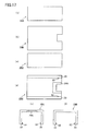
FIGs. 19(a) through 19(c) are drawings (1) illustrating examples of a modular plug, an unlocking mechanism, and a LAN connector according to a fourth embodiment; -
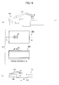
FIGs. 20(a) through 20(c) are drawings (2) illustrating examples of a modular plug, an unlocking mechanism, and a LAN connector according to the fourth embodiment; -
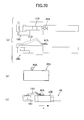
FIGs. 21(a) through 21(c) are drawings (3) illustrating examples of a modular plug, an unlocking mechanism, and a LAN connector according to the fourth embodiment; -
FIGs. 22(a) and 22(b) are drawings (1) used to describe problems in a related-art LAN connector; and -
FIG. 23 is a drawing (2) used to describe problems in a related-art LAN connector. - A first embodiment of the present invention is described below with reference to the accompanying drawings.
FIG. 1 is a perspective view of amodular plug 10 for a LAN cable according to the first embodiment.FIGs. 2(a) through 2(f) are drawings illustrating six sides of themodular plug 10.FIG. 2(a) is a left side view,FIG. 2(b) is a plan view,FIG. 2(c) is a right side view,FIG. 2(d) is a bottom view,FIG. 2(e) is a front view, andFIG. 2(f) is a rear view of themodular plug 10. InFIGs. 1 through 2(f) , the same reference number indicates the same component. - The modular plug 10 (connector protrusion) includes a locking
lever 11, connecting terminals 12 (first connecting terminals),grooves 13, anddowel housings 14. - One end of the locking
lever 11 is fixed to a surface (first surface) of themodular plug 10. The other end of the lockinglever 11 is bent at an acute angle to form a hook-like shape and a middle part of the lockinglever 11 is bent at an obtuse angle. Similar to a release clip of a related-art LAN modular plug, the lockinglever 11 has elasticity. When no force is applied to the lockinglever 11, the lockinglever 11 is in a locking position where themodular plug 10 engages (or is interlocked with) a PCI card (hereafter called a LAN board). When a downward force (toward the LAN cable) is applied to the middle part of the lockinglever 11, themodular plug 10 is unlocked and released from the LAN board. - Like a related-art LAN modular plug, the connecting
terminals 12 are connected with a twisted-pair cable with 8 cores (4 pairs) and used for electric communications between themodular plug 10 and the LAN board. - The
grooves 13 are U-shaped grooves. Assuming that a surface of themodular plug 10 where the connectingterminals 12 are arranged is the front surface, thegrooves 13 are formed in the right and left side surfaces of themodular plug 10. An unlockingmechanism 20 described later engages and slides along thegrooves 13. - The
dowel housings 14 are forhousing dowels 22 of the unlockingmechanism 20 and have a cup shape that fits a dorm shape of thedowels 22. -
FIG. 3 is a perspective view of the unlockingmechanism 20 according to the first embodiment.FIGs. 4(a) through 4(f) are drawings illustrating six sides of the unlockingmechanism 20.FIG. 4(a) is a left side view,FIG. 4(b) is a plan view,FIG. 4(c) is a right side view,FIG. 4(d) is a bottom view,FIG. 4(e) is a front view, andFIG. 4(f) is a rear view of the unlockingmechanism 20. InFIGs. 3 through 4(f) , the same reference number indicates the same component. - The unlocking mechanism 20 (connector frame) has a U-like shape surrounding the
modular plug 10. The unlockingmechanism 20 includes anopening 21, thedowels 22, and engagingparts 23. - The
opening 21 is formed in a surface of thelocking mechanism 20 that opposes the surface of themodular plug 10 to which the lockinglever 11 is fixed. The hook-shaped end of the lockinglever 11 is to fit into theopening 21. - The engaging
parts 23 engage thegrooves 13 to allow the unlockingmechanism 20 to slide over themodular plug 10. The engagingparts 13 are formed by bending the ends of right-side and left-side walls of the unlockingmechanism 20 inward at 90 degrees. - The
dowels 22 limit the sliding movement of the unlockingmechanism 20 with respect to themodular plug 10. Thedowels 22 protrude from the engagingparts 23 and have a dorm shape. Thedowels 22 fit in thedowel housings 14 and thereby limit the sliding movement of the unlockingmechanism 20. -
FIG. 5 is a perspective view of aLAN connector 1 formed by fitting together themodular plug 10 and the unlockingmechanism 20.FIGs. 6(a) through 6(f) are drawings illustrating six sides of theLAN connector 1.FIG. 6(a) is a left side view,FIG. 6(b) is a plan view,FIG. 6(c) is a right side view,FIG. 6(d) is a bottom view,FIG. 6(e) is a front view, andFIG. 6(f) is a rear view of theLAN connector 1. InFIGs. 5 through 6(f) , the same reference number indicates the same component. - The
modular plug 10 and the unlockingmechanism 20 are fitted together to form theLAN connector 1 by engaging thegrooves 13 and the engagingparts 23 and inserting the hook-shaped end of the lockinglever 11 into theopening 21. -
FIGs. 7 (a) and 7(b) are a plan view and a front view of aLAN board 101. - The
LAN board 101 has a configuration similar to that of a related-art LAN board. TheLAN board 101 includes ahousing 111 and connectingterminals 112 to be connected with the connectingterminals 12 of themodular plug 10. Grooves are formed in inner walls of thehousing 111. When themodular plug 10 is inserted into thehousing 111, the lockinglever 11 is pressed down and slides along the grooves. Like a related-art LAN board, theLAN board 101 includes a communicationcontrol circuit board 120 for controlling LAN communications. - An exemplary method of unplugging the
LAN connector 1 from theLAN board 101 according to the first embodiment is described below with reference toFIG. 8 . The method of plugging theLAN connector 1 into thehousing 111 of theLAN board 101 is similar to a related-art method and therefore its descriptions are omitted here. - The user holds the unlocking
mechanism 20 and moves or slides the unlockingmechanism 20 in an unplugging direction (the direction indicated by an arrow "a" inFIG. 8 ) along thegrooves 13 engaging the engagingparts 23. As a result, the hook-shaped end of the lockinglever 11 fits into theopening 21. When the user moves the unlockingmechanism 20 further in the unplugging direction, the bent angle of the middle part of the lockinglever 11 becomes shallower (becomes more obtuse) and the bending point of the middle part moves downward in the direction indicated by an arrow a' inFIG. 8 . - As a result, the locking
lever 11 or theLAN connector 1 is unlocked. Thus, unlike a related-art configuration where a release clip is pressed down with fingers to unlock a LAN connector, the above configuration makes it possible to unlock theLAN connector 1 by just sliding the unlockingmechanism 20. - Accordingly, the above configuration makes it possible to easily unplug a LAN connector from a LAN board without using a tool even when the LAN connector is located in a narrow recess.
- Also, the
dowel housings 14 and thedowels 22 function as a position fixing mechanism for keeping the unlockingmechanism 20 in a fixed position. The position fixing mechanism prevents the unlockingmechanism 20 from being unintentionally moved and thereby prevents theLAN connector 1 from being accidentally unplugged. -
FIG. 9 is a perspective view of an exemplarymodular plug 10A according to a second embodiment.FIGS. 10(a) through 10(f) are drawings illustrating six sides of themodular plug 10A.FIG. 10(a) is a left side view,FIG. 10 (b) is a plan view,FIG. 10 (c) is a right side view,FIG. 10 (d) is a bottom view,FIG. 10 (e) is a front view, andFIG. 10(f) is a rear view of themodular plug 10A. InFIGs. 9 through 10(f) , the same reference number indicates the same component. - The
modular plug 10A (connector protrusion) includes a lockinglever 11A, connecting terminals 12 (first connecting terminals),grooves 13, anddowel housings 14. The connectingterminals 12, thegrooves 13, and thedowel housings 14 have substantially the same configurations and functions as those of the first embodiment and their descriptions are omitted here. - One end of the locking
lever 11A is fixed to a surface (first surface) of themodular plug 10A and a middle part of the lockinglever 11A is bent at an obtuse angle. The other end of the lockinglever 11A is a free end that is positioned near the surface of themodular plug 10A or in contact with the surface of themodular plug 10A. - Similar to a release clip of a related-art LAN modular plug, the locking
lever 11A has elasticity. When no force is applied to the lockinglever 11A, the lockinglever 11A is in a locking position where themodular plug 10A engages (or is interlocked with) a LAN board (e.g., theLAN board 101 ofFIG. 7 ). When a downward force is applied to the middle part of the lockinglever 11A, themodular plug 10A is unlocked and released from the LAN board. -
FIG. 11 is a perspective view of an unlockingmechanism 20A according to the second embodiment.FIGs. 12(a) through 12(f) are drawings illustrating six sides of the unlockingmechanism 20A.FIG. 12(a) is a left side view,FIG. 12(b) is a plan view,FIG. 12(c) is a right side view,FIG. 12(d) is a bottom view,FIG. 12(e) is a front view, andFIG. 12(f) is a rear view of the unlockingmechanism 20A. InFIGS. 11 through 12(f) , the same reference number indicates the same component. - Similar to the unlocking
mechanism 20 of the first embodiment, the unlockingmechanism 20A (connector frame) has a U-shape surrounding themodular plug 10A. The unlockingmechanism 20A includesdowels 22, engagingparts 23, and a locking-lever sliding part 24. - The locking-
lever sliding part 24 assists a part of the lockinglever 11A including at least the free end to slide into a space between the LAN cable and the unlockingmechanism 20A (or a space surrounded by the unlockingmechanism 20A) when the LAN cable is unplugged from the LAN board. - The locking
lever sliding part 24 is formed in an inner wall of the unlockingmechanism 20A that faces the surface of themodular plug 10A to which the lockinglever 11A is fixed. In other words, the locking-lever sliding part 24 is a recess through which the lockinglever 11A slides into the unlockingmechanism 20A and is a part of a wall of the unlockingmechanism 20A having a thickness that is less than the thickness of other walls. The locking-lever sliding part 24 increases the gap between the unlockingmechanism 20A and the LAN cable and makes it easier for the free end of the lockinglever 11A to slide into the unlockingmechanism 20A. - The
dowels 22 and the engagingparts 23 have substantially the same configurations and functions as those of the first embodiment and therefore their descriptions are omitted here. -
FIG. 13 is a perspective view of aLAN connector 1A formed by fitting together themodular plug 10A and the unlockingmechanism 20A.FIGs. 14(a) through 14(f) are drawings illustrating six sides of theLAN connector 1A.FIG. 14(a) is a left side view,FIG. 14(b) is a plan view,FIG. 14(c) is a right side view,FIG. 14 (d) is a bottom view,FIG. 14 (e) is a front view, andFIG. 14(f) is a rear view of theLAN connector 1A. InFIGs. 13 through 14(f) , the same reference number indicates the same component. - The
modular plug 10A and the unlockingmechanism 20A are fitted together to form theLAN connector 1A by engaging thegrooves 13 and the engagingparts 23. - An exemplary method of unplugging the
LAN connector 1A from the LAN board (e.g., theLAN board 101 ofFIG. 7 ) according to the second embodiment is described below with reference toFIG. 15 . The method of plugging theLAN connector 1A into thehousing 111 of theLAN board 101 is similar to a related-art method and therefore its descriptions are omitted here. - The user holds the unlocking
mechanism 20A and moves or slides the unlockingmechanism 20A toward themodular plug 10A (in the direction indicated by an arrow "b" inFIG. 15 ) along thegrooves 13 engaging the engagingparts 23. As a result, the free end of the lockinglever 11A touches the locking-lever sliding part 24 of the unlockingmechanism 20A. When the unlockingmechanism 20A is moved further in the direction "b", the free end of the lockinglever 11A slides into the space between the LAN cable and the inner wall of the unlockingmechanism 20A. - The inner wall of the unlocking
mechanism 20A presses the lockinglever 11A in the direction "b" and causes the lockinglever 11A to slide further into the unlockingmechanism 20A. As the lockinglever 11A slides into the unlockingmechanism 20A, the bent angle of the middle part of the lockinglever 11A becomes shallower (becomes more obtuse) and the bending point of the middle part moves downward in the direction indicated by an arrow b' inFIG. 15 . - As a result, the locking
lever 11A or theLAN connector 1A is unlocked. Thus, unlike a related-art configuration where a release clip is pressed down with fingers to unlock a LAN connector, the above configuration makes it possible to unlock theLAN connector 1A by just sliding the unlockingmechanism 20A. Accordingly, the above configuration makes it possible to easily unplug a LAN connector from a LAN board even when the LAN connector is located in a narrow recess. - The unlocking
mechanism 20A of the second embodiment may be normally separated from themodular plug 10A and attached to themodular plug 10A when unplugging theLAN connector 1A from the LAN board. With the configuration of the second embodiment, however, it is difficult to identify the position of the locking-lever sliding part 24 from the outside of the unlockingmechanism 20A when fitting together the unlockingmechanism 20A and themodular plug 10A. - In a third embodiment, the shape of the locking-
lever sliding part 24 of the unlockingmechanism 20A is changed to solve this problem.FIG. 16 is a perspective view of an unlockingmechanism 20B according to the third embodiment.FIGs. 17(a) through 17(f) are drawings illustrating six sides of the unlockingmechanism 20B.FIG. 17(a) is a left side view,FIG. 17(b) is a plan view,FIG. 17(c) is a right side view,FIG. 17(d) is a bottom view,FIG. 17 (e) is a front view, andFIG. 17(f) is a rear view of the unlockingmechanism 20B. InFIGs. 16 through 17(f) , the same reference number indicates the same component. - The unlocking
mechanism 20B includesdowels 22, engagingparts 23, and a locking-lever sliding part 24A. Thedowels 22 and the engagingparts 23 have substantially the same configurations and functions as those of the first and second embodiments and therefore their descriptions are omitted here. - Different from the locking-
lever sliding part 24 of the second embodiment, the locking-lever sliding part 24A is open to the outside via the upper surface of the unlockingmechanism 20B so that the locking-lever sliding part 24A can be identified from the outside of the unlockingmechanism 20B. -
FIG. 18 is a perspective view of aLAN connector 1B according to the third embodiment. TheLAN connector 1B includes themodular plug 10A of the second embodiment and the unlockingmechanism 20B described above. The method of unplugging theLAN connector 1B is substantially the same as that of the second embodiment and therefore its descriptions are omitted here. - With the
LAN connector 1 of the first embodiment, one end of the lockinglever 11 fits into theopening 21 of the unlockingmechanism 20 and the lockinglever 11 and the unlockingmechanism 20 are thereby connected to each other. When the unlockingmechanism 20 is moved in the unplugging direction, the lockinglever 11 is unlocked and themodular plug 10 is unplugged from the LAN board. - This indicates that it is possible to unlock a locking lever by moving an unlocking mechanism as in the first embodiment as long as the locking lever and the unlocking mechanism are connected to each other. In a fourth embodiment, other exemplary configurations for connecting the unlocking mechanism and the locking lever are described with reference to
FIGs. 19(a) through 21(c) . - A first exemplary configuration is described below with reference to
FIGs. 19(a) through 19(c). FIG. 19 (a) is a side view of amodular plug 10B,FIG. 19 (b) is a plan view and a cross-sectional view of an unlockingmechanism 20C, andFIG. 19(c) is a side view of a LAN connector 1C formed by connecting themodular plug 10B and the unlockingmechanism 20C. - The
modular plug 10B includes a lockinglever 11C having a spherical end 61 (seeFIG. 19(a) ). The unlockingmechanism 20C includes anend receiving part 62 on the upper surface which is to be fitted together with theend 61 of the lockinglever 11C (seeFIG. 19(b) ). - The
modular plug 10B and the unlockingmechanism 20C are connected to each other by fitting theend 61 of the lockinglever 11C into theend receiving part 62 of the unlockingmechanism 20C (seeFIG. 19(c) ). As in the first embodiment, when the unlockingmechanism 20C is moved in an unplugging direction indicated by an arrow "a" inFIG. 19(c) , the LAN connector 1C is unlocked and released from the LAN board. - A second exemplary configuration is described below with reference to
FIGs. 20(a) through 20 (c). FIG. 20 (a) is a plan view and a side view of amodular plug 10C,FIG. 20(b) is a side view of an unlockingmechanism 20D, andFIG. 20(c) is a side view of aLAN connector 1D formed by connecting themodular plug 10C and the unlockingmechanism 20D. - The
modular plug 10C includes a lockinglever 11D. Ahole 61A to be fitted together with aspherical protrusion 62A is formed in one end of the lockinglever 11D (seeFIG. 20(a) ). The unlockingmechanism 20D includes thespherical protrusion 62A on the upper surface which is fitted into thehole 61A of the lockinglever 11D (seeFIG. 20(b) ). - The
modular plug 10C and the unlockingmechanism 20D are connected to each other by fitting thespherical protrusion 62A of the unlockingmechanism 20D into thehole 61A of the lockinglever 11D (seeFIG. 20(c) ). As in the first embodiment, when the unlockingmechanism 20D is moved in an unplugging direction indicated by an arrow "a" inFIG. 20(c) , theLAN connector 1D is unlocked and released from the LAN board. - A third exemplary configuration is described below with reference to
FIGs. 21(a) through 21(c). FIG. 21(a) is a plan view and a side view of amodular plug 10D,FIG. 21(b) is a side view of an unlockingmechanism 20E, andFIG. 21(c) is a side view of a LAN connector 1E formed by connecting themodular plug 10D and the unlockingmechanism 20E. - The
modular plug 10D includes a lockinglever 11E having anend 61B that is bent to become orthogonal to the upper surface of themodular plug 10D (seeFIG. 21(a) ). Ahole 61A as shown inFIG. 20(a) is formed in theend 61B. The unlockingmechanism 20E includes a connectingpart 62B including aspherical protrusion 62A as shown inFIG. 20(b) and a trapezoidal support part supporting thespherical protrusion 62A in a horizontal position (seeFIG. 21(b) ). - The
modular plug 10D and the unlockingmechanism 20E are connected to each other by fitting together theend 61B of the lockinglever 11D and the connectingpart 62B of the unlockingmechanism 20E (seeFIG. 21(c) ). As in the first embodiment, when the unlockingmechanism 20E is moved in an unplugging direction indicated by an arrow "a" inFIG. 21(c) , the LAN connector 1E is unlocked and released from the LAN board. - In the present application, a connecting unit may indicate a combination of the
LAN connector 1 of the first embodiment, thehousing 111, and the connectingterminals 112, or a combination of theLAN connector 1A of the second embodiment, thehousing 111, and the connectingterminals 112. - Also, a connecting unit may indicate a combination of the
LAN connector 1B of the third embodiment, thehousing 111, and the connectingterminals 112. Further, a connecting unit may indicate a combination of theLAN connector 1C, 1D, or 1E of the fourth embodiment, thehousing 111, and the connectingterminals 112. - In the present application, an electronic device may indicate a combination of the
LAN connector 1 of the first embodiment, thehousing 111, the connectingterminals 112, and the communicationcontrol circuit board 120, or a combination of theLAN connector 1A of the second embodiment, thehousing 111, the connectingterminals 112, and the communicationcontrol circuit board 120. - Also, an electronic device may indicate a combination of the
LAN connector 1B of the third embodiment, thehousing 111, the connectingterminals 112, and the communicationcontrol circuit board 120. Further, an electronic device may indicate a combination of theLAN connector 1C, 1D, or 1E of the fourth embodiment, thehousing 111, the connectingterminals 112, and the communicationcontrol circuit board 120. - As described above, an aspect of the embodiments makes it possible to easily unplug a LAN connector from a LAN board without using a tool even when the LAN board is located in a recess, and thereby makes it possible to improve the reliability of a LAN connector and to reduce the workload.
Claims (14)
- A connecting unit, comprising:a connector protrusion including a locking lever provided on a first surface and a first connecting terminal provided on a second surface opposing the first surface or on a front surface;a connector socket including a second connecting terminal to be connected with the first connecting terminal and a housing having a groove formed in an inner wall so that the locking lever is pressed down and slides along the groove when the connector protrusion is inserted into the connector socket; anda connector frame that surrounds the connector protrusion and has an opening in a surface opposing the first surface of the connector protrusion,wherein the connector frame is configured such that when the connector frame is moved in a direction opposite to a direction where the connector protrusion is inserted while the connector protrusion is in the connector socket, an end of the locking lever fits into the opening and the locking lever is unlocked.
- The connecting unit as claimed in claim 1,
wherein
the connector protrusion further includes a first groove formed in a first side surface of the connector protrusion and a second groove formed in a second side surface opposing the first side surface; and
the connector frame further includes a first engaging part configured to engage and slide along the first groove and a second engaging part configured to engage and slide along the second groove. - The connecting unit as claimed in claim 2, wherein a cross section of the connector frame has a U-like shape.
- An electronic device, comprising:a connector socket into which a connector protrusion is to be inserted, the connector protrusion being surrounded by a connector frame and including a locking lever provided on a first surface and a first connecting terminal provided on a second surface opposing the first surface or on a front surface, whereinthe connector socket includes a second connecting terminal to be connected with the first connecting terminal and a housing having a groove formed in an inner wall so that the locking lever is pressed down and slides along the groove when the connector protrusion is inserted into the connector socket; andthe connector frame has an opening in a surface opposing the first surface of the connector protrusion and is configured such that when the connector frame is moved in a direction opposite to a direction where the connector protrusion is inserted while the connector protrusion is in the connector socket, an end of the locking lever fits into the opening and the locking lever is unlocked.
- The electronic device as claimed in claim 4, wherein
the connector protrusion further includes a first groove formed in a first side surface of the connector protrusion and a second groove formed in a second side surface opposing the first side surface; and
the connector frame further includes a first engaging part configured to engage and slide along the first groove and a second engaging part configured to engage and slide along the second groove. - The electronic device as claimed in claim 5, wherein a cross section of the connector frame has a U-like shape.
- A method of unplugging a connector protrusion of a connecting unit from a connector socket of the connecting unit, wherein
the connector protrusion includes a locking lever provided on a first surface and a first connecting terminal provided on a second surface opposing the first surface or on a front surface;
the connector socket includes a second connecting terminal to be connected with the first connecting terminal and a housing having a groove formed in an inner wall so that the locking lever is pressed down and slides along the groove when the connector protrusion is inserted into the connector socket; and
the connecting unit further includes a connector frame surrounding the connector protrusion and having an opening in a surface opposing the first surface of the connector protrusion, the method comprising:fitting an end of the locking lever into the opening of the connector frame while the connector protrusion is in the connector socket; andmoving the connector frame in a direction opposite to a direction where the connector protrusion is inserted into the connector socket to unlock the locking lever. - A connecting unit, comprising:a connector protrusion including a locking lever provided on a first surface and a first connecting terminal provided on a second surface opposing the first surface or on a front surface;
a connector socket including a second connecting terminal to be connected with the first connecting terminal and a housing having a groove formed in an inner wall so that the locking lever is pressed down and slides along the groove when the connector protrusion is inserted into the connector socket; and
a connector frame that surrounds the connector protrusion,
wherein the connector frame is configured such that when the connector frame is pressed in a direction where the connector protrusion is inserted, an end of the locking lever slides into a space surrounded by the connector frame and the locking lever is unlocked. - The connecting unit as claimed in claim 8, wherein
the connector protrusion further includes a first groove formed in a first side surface of the connector protrusion and a second groove formed in a second side surface opposing the first side surface; and
the connector frame further includes a first engaging part configured to engage and slide along the first groove and a second engaging part configured to engage and slide along the second groove. - The connecting unit as claimed in claim 9, wherein a cross section of the connector frame has a U-like shape.
- An electronic device, comprising:a connector socket into which a connector protrusion is to be inserted, the connector protrusion being surrounded by a connector frame and including a locking lever provided on a first surface and a first connecting terminal provided on a second surface opposing the first surface or on a front surface, whereinthe connector socket includes a second connecting terminal to be connected with the first connecting terminal and a housing having a groove formed in an inner wall so that the locking lever is pressed down and slides along the groove when the connector protrusion is inserted into the connector socket; andthe connector frame is configured such that when the connector frame is pressed in a direction where the connector protrusion is inserted, an end of the locking lever slides into a space surrounded by the connector frame and the locking lever is unlocked.
- The electronic device as claimed in claim 11, wherein
the connector protrusion further includes a first groove formed in a first side surface of the connector protrusion and a second groove formed in a second side surface opposing the first side surface; and
the connector frame further includes a first engaging part configured to engage and slide along the first groove and a second engaging part configured to engage and slide along the second groove. - The electronic device as claimed in claim 12, wherein a cross section of the connector frame has a U-like shape.
- A method of unplugging a connector protrusion of a connecting unit from a connector socket of the connecting unit, wherein
the connector protrusion includes a locking lever provided on a first surface and a first connecting terminal provided on a second surface opposing the first surface or on a front surface;
the connector socket includes a second connecting terminal to be connected with the first connecting terminal and a housing having a groove formed in an inner wall so that the locking lever is pressed down and slides along the groove when the connector protrusion is inserted into the connector socket; and
the connecting unit further includes a connector frame surrounding the connector protrusion, the method comprising:
pressing the connector frame in a direction where the connector protrusion is inserted; and
thereby causing an end of the locking lever to slide into a space surrounded by the connector frame to unlock the locking lever.
Applications Claiming Priority (1)
| Application Number | Priority Date | Filing Date | Title |
|---|---|---|---|
| PCT/JP2008/067806 WO2010038283A1 (en) | 2008-10-01 | 2008-10-01 | Connector, electronic apparatus, method for removing connector |
Publications (3)
| Publication Number | Publication Date |
|---|---|
| EP2337163A1 true EP2337163A1 (en) | 2011-06-22 |
| EP2337163A4 EP2337163A4 (en) | 2012-10-17 |
| EP2337163B1 EP2337163B1 (en) | 2020-07-29 |
Family
ID=42073076
Family Applications (1)
| Application Number | Title | Priority Date | Filing Date |
|---|---|---|---|
| EP08877142.3A Active EP2337163B1 (en) | 2008-10-01 | 2008-10-01 | Connector, electronic apparatus, method for removing connector |
Country Status (6)
| Country | Link |
|---|---|
| US (2) | US8187018B2 (en) |
| EP (1) | EP2337163B1 (en) |
| JP (1) | JP5195916B2 (en) |
| KR (1) | KR101185809B1 (en) |
| CN (1) | CN102171893B (en) |
| WO (1) | WO2010038283A1 (en) |
Cited By (12)
| Publication number | Priority date | Publication date | Assignee | Title |
|---|---|---|---|---|
| WO2013124785A1 (en) * | 2012-02-20 | 2013-08-29 | Tyco Electronics (Shanghai) Co. Ltd. | Connector and connector assembly |
| WO2014099840A1 (en) * | 2012-12-21 | 2014-06-26 | 3M Innovative Properties Company | Electrical connector |
| WO2015100151A1 (en) * | 2013-12-26 | 2015-07-02 | 3M Innovative Properties Company | Electrical connector |
| EP2953212A1 (en) | 2014-06-05 | 2015-12-09 | Wago Verwaltungsgesellschaft mbH | Connector assembly and loosening element for same |
| US9761998B2 (en) | 2011-02-08 | 2017-09-12 | Commscope Technologies Llc | Release tab for an electrical connector and electrical connector comprising said release tab |
| US9825403B2 (en) | 2011-02-08 | 2017-11-21 | Commscope Technologies Llc | RJ type connector including a disengagement feature acting on the latch of the connector |
| US10067301B2 (en) | 2014-01-13 | 2018-09-04 | Commscope Connectivity Uk Limited | Fiber optic connector |
| DE202019101806U1 (en) * | 2019-03-29 | 2020-07-02 | Wago Verwaltungsgesellschaft Mbh | Electrical connector assembly and holding element therefor |
| US11215767B2 (en) | 2017-06-07 | 2022-01-04 | Commscope Technologies Llc | Fiber optic adapter and cassette |
| US11327240B2 (en) | 2017-09-15 | 2022-05-10 | Commscope Technologies Llc | Fiber optic connector with boot-integrated release and related assemblies |
| US12345925B2 (en) | 2020-05-29 | 2025-07-01 | Commscope Technologies Llc | Telecommunications connector with latch release mechanism |
| US12523821B2 (en) | 2021-04-08 | 2026-01-13 | Commscope Technologies Llc | Telecommunications connector with latch release mechanism |
Families Citing this family (17)
| Publication number | Priority date | Publication date | Assignee | Title |
|---|---|---|---|---|
| CN103703631B (en) * | 2011-10-05 | 2017-02-15 | 扇港元器件有限公司 | Latching connector with remote release |
| DE202011052551U1 (en) * | 2011-12-31 | 2012-05-22 | Zellner Gmbh | Plug for a data cable |
| JP2014085444A (en) * | 2012-10-22 | 2014-05-12 | Sei Optifrontier Co Ltd | Connector and operation member and method for inserting and extracting connector |
| JP5677478B2 (en) * | 2013-02-06 | 2015-02-25 | 中国電力株式会社 | Connector boots |
| JP5298254B1 (en) * | 2013-03-11 | 2013-09-25 | 日本製線株式会社 | Modular plug |
| US8979569B2 (en) * | 2013-03-15 | 2015-03-17 | Ortronics, Inc. | Modular connectors and associated systems and methods |
| CN203326271U (en) * | 2013-06-20 | 2013-12-04 | 宁波卓新通讯接插件有限公司 | Network connector which can be pulled out easily |
| US9048580B2 (en) * | 2013-09-17 | 2015-06-02 | Ningbo Excellence Communicated Connector Co., Ltd. | Easy-pull male network connector and tool combination |
| US9401577B2 (en) | 2014-08-01 | 2016-07-26 | Echostar Technologies L.L.C. | RJ-45 insertion and extraction tool |
| JP6080922B2 (en) * | 2015-08-26 | 2017-02-15 | スリーエム イノベイティブ プロパティズ カンパニー | Electrical connector |
| CN106207563B (en) * | 2016-08-31 | 2019-03-26 | 维尔斯电子(昆山)有限公司 | A kind of self-locking plug adapter and power supply line |
| USD815601S1 (en) * | 2016-12-02 | 2018-04-17 | You Hung International Co., Ltd. | Cable connector |
| USD832791S1 (en) * | 2017-09-22 | 2018-11-06 | Cheng Uei Precision Industry Co., Ltd. | Plug connector |
| US10830963B2 (en) | 2017-11-17 | 2020-11-10 | Commscope Technologies Llc | Fiber optic connector locking feature |
| US20220196920A1 (en) * | 2020-12-22 | 2022-06-23 | Commscope Technologies Llc | Delatching devices for fiber optic connectors |
| CN114243380B (en) * | 2021-12-10 | 2024-01-12 | 深圳市麦电创新科技有限公司 | Internet remote control type power adapter |
| KR102819350B1 (en) * | 2024-04-29 | 2025-06-10 | 엘아이지넥스원 주식회사 | Cable connector and connection apparatus comprising the Same |
Family Cites Families (18)
| Publication number | Priority date | Publication date | Assignee | Title |
|---|---|---|---|---|
| JPS63184271A (en) * | 1987-01-27 | 1988-07-29 | 松下電工株式会社 | Modular plug |
| JP2893760B2 (en) | 1989-10-30 | 1999-05-24 | 日本電気株式会社 | Pattern normalizer |
| JP3144788B2 (en) | 1989-12-15 | 2001-03-12 | 株式会社日立製作所 | Color document image processing device |
| JPH05152030A (en) * | 1991-11-29 | 1993-06-18 | Fujitsu Ltd | Connector housing |
| JPH08273749A (en) * | 1995-04-03 | 1996-10-18 | Japan Aviation Electron Ind Ltd | Connector locking mechanism |
| JP3362014B2 (en) * | 1999-06-29 | 2003-01-07 | エヌイーシートーキン株式会社 | Lock and unlock structure of cable connector and method of locking and unlocking |
| US7037129B2 (en) | 2002-04-26 | 2006-05-02 | The Siemon Company | Axial latch actuator with locking wedge |
| WO2003091517A2 (en) * | 2002-04-26 | 2003-11-06 | The Siemon Company | Axial latch actuator |
| DE10324794B3 (en) | 2003-05-31 | 2004-12-09 | Woodhead Connectivity Gmbh | Electrical connector |
| JP2005235545A (en) | 2004-02-19 | 2005-09-02 | Oki Electric Cable Co Ltd | Connector with attachment and detachment mechanism |
| JP2006011102A (en) * | 2004-06-28 | 2006-01-12 | Sumitomo Electric Ind Ltd | Optical connector |
| WO2006047258A1 (en) * | 2004-10-22 | 2006-05-04 | Panduit Corp. | Push-pull plugs and tools |
| US7101212B1 (en) * | 2005-03-07 | 2006-09-05 | Kevin Larkin | Snagless plug and boot connection |
| JP4198129B2 (en) * | 2005-06-07 | 2008-12-17 | 株式会社Ntt西日本−東海 | Cable connector insertion / extraction tool |
| US7052186B1 (en) * | 2005-06-08 | 2006-05-30 | Itt Manufacturing Enterprises, Inc. | Secondary latch sleeve for connector connections |
| US7329137B2 (en) * | 2005-10-05 | 2008-02-12 | Tyco Electronics Corporation | Modular plug with slider latch |
| JP4832183B2 (en) * | 2006-06-27 | 2011-12-07 | 富士通株式会社 | Modular plug |
| JP3144788U (en) * | 2008-07-01 | 2008-09-11 | 大明株式会社 | Modular plug insertion / extraction tool |
-
2008
- 2008-10-01 KR KR1020117007430A patent/KR101185809B1/en not_active Expired - Fee Related
- 2008-10-01 JP JP2010531677A patent/JP5195916B2/en not_active Expired - Fee Related
- 2008-10-01 EP EP08877142.3A patent/EP2337163B1/en active Active
- 2008-10-01 CN CN2008801313646A patent/CN102171893B/en not_active Expired - Fee Related
- 2008-10-01 WO PCT/JP2008/067806 patent/WO2010038283A1/en not_active Ceased
-
2011
- 2011-03-31 US US13/064,572 patent/US8187018B2/en not_active Expired - Fee Related
-
2012
- 2012-04-26 US US13/456,956 patent/US8317532B2/en not_active Expired - Fee Related
Cited By (25)
| Publication number | Priority date | Publication date | Assignee | Title |
|---|---|---|---|---|
| US12088044B2 (en) | 2011-02-08 | 2024-09-10 | Commscope Technologies Llc | Connector including a disengagement feature |
| US11742617B2 (en) | 2011-02-08 | 2023-08-29 | Commscope Technologies Llc | RJ type connector including a disengagement feature acting on the latch of the connector |
| US11322889B2 (en) | 2011-02-08 | 2022-05-03 | Commscope Technologies Llc | RJ type connector including a disengagement feature acting on the latch of the connector |
| US9761998B2 (en) | 2011-02-08 | 2017-09-12 | Commscope Technologies Llc | Release tab for an electrical connector and electrical connector comprising said release tab |
| US9825403B2 (en) | 2011-02-08 | 2017-11-21 | Commscope Technologies Llc | RJ type connector including a disengagement feature acting on the latch of the connector |
| US9991635B2 (en) | 2011-02-08 | 2018-06-05 | Commscope Technologies Llc | Release tab for an electrical connector and electrical connector comprising said release tab |
| WO2013124785A1 (en) * | 2012-02-20 | 2013-08-29 | Tyco Electronics (Shanghai) Co. Ltd. | Connector and connector assembly |
| WO2014099840A1 (en) * | 2012-12-21 | 2014-06-26 | 3M Innovative Properties Company | Electrical connector |
| WO2015100151A1 (en) * | 2013-12-26 | 2015-07-02 | 3M Innovative Properties Company | Electrical connector |
| US11079556B2 (en) | 2014-01-13 | 2021-08-03 | Commscope Connectivity Uk Limited | Fiber optic connector |
| US11604319B2 (en) | 2014-01-13 | 2023-03-14 | Commscope Connectivity Uk Limited | Fiber optic connector |
| US12353026B2 (en) | 2014-01-13 | 2025-07-08 | Commscope Connectivity Uk Limited | Fiber optic connector |
| US10067301B2 (en) | 2014-01-13 | 2018-09-04 | Commscope Connectivity Uk Limited | Fiber optic connector |
| US10545296B2 (en) | 2014-01-13 | 2020-01-28 | Commscope Connectivity Uk Limited | Fiber optic connector |
| EP2953212A1 (en) | 2014-06-05 | 2015-12-09 | Wago Verwaltungsgesellschaft mbH | Connector assembly and loosening element for same |
| DE102014107950B4 (en) | 2014-06-05 | 2022-02-03 | Wago Verwaltungsgesellschaft Mbh | Connector assembly and release element for this |
| US9478907B2 (en) | 2014-06-05 | 2016-10-25 | Wago Verwaltungsgesellschaft Mbh | Plug-type connector arrangement and detachment element therefor |
| DE102014107950A1 (en) * | 2014-06-05 | 2015-12-17 | Wago Verwaltungsgesellschaft Mbh | Connector assembly and release element for this purpose |
| US11650378B2 (en) | 2017-06-07 | 2023-05-16 | Commscope Technologies Llc | Fiber optic adapter and cassette |
| US11215767B2 (en) | 2017-06-07 | 2022-01-04 | Commscope Technologies Llc | Fiber optic adapter and cassette |
| US11592626B2 (en) | 2017-09-15 | 2023-02-28 | Commscope Technologies Llc | Fiber optic connector with boot-integrated release and related assemblies |
| US11327240B2 (en) | 2017-09-15 | 2022-05-10 | Commscope Technologies Llc | Fiber optic connector with boot-integrated release and related assemblies |
| DE202019101806U1 (en) * | 2019-03-29 | 2020-07-02 | Wago Verwaltungsgesellschaft Mbh | Electrical connector assembly and holding element therefor |
| US12345925B2 (en) | 2020-05-29 | 2025-07-01 | Commscope Technologies Llc | Telecommunications connector with latch release mechanism |
| US12523821B2 (en) | 2021-04-08 | 2026-01-13 | Commscope Technologies Llc | Telecommunications connector with latch release mechanism |
Also Published As
| Publication number | Publication date |
|---|---|
| JPWO2010038283A1 (en) | 2012-02-23 |
| US8187018B2 (en) | 2012-05-29 |
| US20120208388A1 (en) | 2012-08-16 |
| US8317532B2 (en) | 2012-11-27 |
| CN102171893B (en) | 2013-10-16 |
| EP2337163B1 (en) | 2020-07-29 |
| US20110183541A1 (en) | 2011-07-28 |
| WO2010038283A1 (en) | 2010-04-08 |
| EP2337163A4 (en) | 2012-10-17 |
| JP5195916B2 (en) | 2013-05-15 |
| KR101185809B1 (en) | 2012-10-02 |
| KR20110049903A (en) | 2011-05-12 |
| CN102171893A (en) | 2011-08-31 |
Similar Documents
| Publication | Publication Date | Title |
|---|---|---|
| EP2337163B1 (en) | Connector, electronic apparatus, method for removing connector | |
| CN104205507B (en) | Board mounted electrical connector | |
| CN104321936B (en) | Electric connector breech lock | |
| CN105051981B (en) | Board Mount Electrical Connector Assemblies | |
| CN104145377B (en) | Electric connector contact terminal | |
| CN101238614B (en) | Plug insurance device | |
| CN104170172A (en) | Wire mount electrical connector | |
| US9876297B2 (en) | Connector | |
| US7465185B2 (en) | Electrical connector assembly with mate-assist and a wire dress cover | |
| CN104412458A (en) | Electrical connector strain relief | |
| TW201027856A (en) | Connector of a simple structure having a locking mechanism | |
| EP1978606A2 (en) | Slide lock panel-mount connector | |
| US11594839B2 (en) | Plug connector assembly | |
| CN103887654B (en) | For separating patch cord and the release mechanism of separate port component | |
| CN103457059A (en) | Electrical connector | |
| CN107408782A (en) | Wire and cable connector | |
| CN103441378A (en) | Connector | |
| CN104205510A (en) | Galvanic coupling element | |
| JP5953431B2 (en) | Blade server slide-in module equipment | |
| CN112886324B (en) | Electric connection device | |
| CN108711686B (en) | Connector and connector assembly | |
| CN107230885A (en) | The connector of with locking mechanism | |
| JP4173155B2 (en) | Board to board connector | |
| JP3897744B2 (en) | Relay connector | |
| CN121079854A (en) | Plug connector device |
Legal Events
| Date | Code | Title | Description |
|---|---|---|---|
| PUAI | Public reference made under article 153(3) epc to a published international application that has entered the european phase |
Free format text: ORIGINAL CODE: 0009012 |
|
| 17P | Request for examination filed |
Effective date: 20110427 |
|
| AK | Designated contracting states |
Kind code of ref document: A1 Designated state(s): AT BE BG CH CY CZ DE DK EE ES FI FR GB GR HR HU IE IS IT LI LT LU LV MC MT NL NO PL PT RO SE SI SK TR |
|
| AX | Request for extension of the european patent |
Extension state: AL BA MK RS |
|
| DAX | Request for extension of the european patent (deleted) | ||
| A4 | Supplementary search report drawn up and despatched |
Effective date: 20120913 |
|
| RIC1 | Information provided on ipc code assigned before grant |
Ipc: H01R 13/633 20060101AFI20120907BHEP Ipc: H01R 24/00 20110101ALI20120907BHEP |
|
| 17Q | First examination report despatched |
Effective date: 20160111 |
|
| STAA | Information on the status of an ep patent application or granted ep patent |
Free format text: STATUS: EXAMINATION IS IN PROGRESS |
|
| GRAP | Despatch of communication of intention to grant a patent |
Free format text: ORIGINAL CODE: EPIDOSNIGR1 |
|
| STAA | Information on the status of an ep patent application or granted ep patent |
Free format text: STATUS: GRANT OF PATENT IS INTENDED |
|
| INTG | Intention to grant announced |
Effective date: 20200220 |
|
| GRAS | Grant fee paid |
Free format text: ORIGINAL CODE: EPIDOSNIGR3 |
|
| GRAA | (expected) grant |
Free format text: ORIGINAL CODE: 0009210 |
|
| STAA | Information on the status of an ep patent application or granted ep patent |
Free format text: STATUS: THE PATENT HAS BEEN GRANTED |
|
| AK | Designated contracting states |
Kind code of ref document: B1 Designated state(s): AT BE BG CH CY CZ DE DK EE ES FI FR GB GR HR HU IE IS IT LI LT LU LV MC MT NL NO PL PT RO SE SI SK TR |
|
| REG | Reference to a national code |
Ref country code: GB Ref legal event code: FG4D |
|
| REG | Reference to a national code |
Ref country code: CH Ref legal event code: EP |
|
| REG | Reference to a national code |
Ref country code: DE Ref legal event code: R096 Ref document number: 602008063069 Country of ref document: DE |
|
| REG | Reference to a national code |
Ref country code: AT Ref legal event code: REF Ref document number: 1296895 Country of ref document: AT Kind code of ref document: T Effective date: 20200815 |
|
| REG | Reference to a national code |
Ref country code: IE Ref legal event code: FG4D |
|
| PGFP | Annual fee paid to national office [announced via postgrant information from national office to epo] |
Ref country code: FR Payment date: 20200929 Year of fee payment: 13 |
|
| REG | Reference to a national code |
Ref country code: LT Ref legal event code: MG4D |
|
| REG | Reference to a national code |
Ref country code: NL Ref legal event code: MP Effective date: 20200729 |
|
| REG | Reference to a national code |
Ref country code: DE Ref legal event code: R082 Ref document number: 602008063069 Country of ref document: DE Representative=s name: HL KEMPNER PATENTANWALT, RECHTSANWALT, SOLICIT, DE |
|
| REG | Reference to a national code |
Ref country code: AT Ref legal event code: MK05 Ref document number: 1296895 Country of ref document: AT Kind code of ref document: T Effective date: 20200729 |
|
| PG25 | Lapsed in a contracting state [announced via postgrant information from national office to epo] |
Ref country code: SE Free format text: LAPSE BECAUSE OF FAILURE TO SUBMIT A TRANSLATION OF THE DESCRIPTION OR TO PAY THE FEE WITHIN THE PRESCRIBED TIME-LIMIT Effective date: 20200729 Ref country code: PT Free format text: LAPSE BECAUSE OF FAILURE TO SUBMIT A TRANSLATION OF THE DESCRIPTION OR TO PAY THE FEE WITHIN THE PRESCRIBED TIME-LIMIT Effective date: 20201130 Ref country code: NO Free format text: LAPSE BECAUSE OF FAILURE TO SUBMIT A TRANSLATION OF THE DESCRIPTION OR TO PAY THE FEE WITHIN THE PRESCRIBED TIME-LIMIT Effective date: 20201029 Ref country code: ES Free format text: LAPSE BECAUSE OF FAILURE TO SUBMIT A TRANSLATION OF THE DESCRIPTION OR TO PAY THE FEE WITHIN THE PRESCRIBED TIME-LIMIT Effective date: 20200729 Ref country code: BG Free format text: LAPSE BECAUSE OF FAILURE TO SUBMIT A TRANSLATION OF THE DESCRIPTION OR TO PAY THE FEE WITHIN THE PRESCRIBED TIME-LIMIT Effective date: 20201029 Ref country code: AT Free format text: LAPSE BECAUSE OF FAILURE TO SUBMIT A TRANSLATION OF THE DESCRIPTION OR TO PAY THE FEE WITHIN THE PRESCRIBED TIME-LIMIT Effective date: 20200729 Ref country code: HR Free format text: LAPSE BECAUSE OF FAILURE TO SUBMIT A TRANSLATION OF THE DESCRIPTION OR TO PAY THE FEE WITHIN THE PRESCRIBED TIME-LIMIT Effective date: 20200729 Ref country code: LT Free format text: LAPSE BECAUSE OF FAILURE TO SUBMIT A TRANSLATION OF THE DESCRIPTION OR TO PAY THE FEE WITHIN THE PRESCRIBED TIME-LIMIT Effective date: 20200729 Ref country code: GR Free format text: LAPSE BECAUSE OF FAILURE TO SUBMIT A TRANSLATION OF THE DESCRIPTION OR TO PAY THE FEE WITHIN THE PRESCRIBED TIME-LIMIT Effective date: 20201030 Ref country code: FI Free format text: LAPSE BECAUSE OF FAILURE TO SUBMIT A TRANSLATION OF THE DESCRIPTION OR TO PAY THE FEE WITHIN THE PRESCRIBED TIME-LIMIT Effective date: 20200729 |
|
| PGFP | Annual fee paid to national office [announced via postgrant information from national office to epo] |
Ref country code: DE Payment date: 20201021 Year of fee payment: 13 Ref country code: GB Payment date: 20201021 Year of fee payment: 13 |
|
| PG25 | Lapsed in a contracting state [announced via postgrant information from national office to epo] |
Ref country code: IS Free format text: LAPSE BECAUSE OF FAILURE TO SUBMIT A TRANSLATION OF THE DESCRIPTION OR TO PAY THE FEE WITHIN THE PRESCRIBED TIME-LIMIT Effective date: 20201129 Ref country code: LV Free format text: LAPSE BECAUSE OF FAILURE TO SUBMIT A TRANSLATION OF THE DESCRIPTION OR TO PAY THE FEE WITHIN THE PRESCRIBED TIME-LIMIT Effective date: 20200729 Ref country code: PL Free format text: LAPSE BECAUSE OF FAILURE TO SUBMIT A TRANSLATION OF THE DESCRIPTION OR TO PAY THE FEE WITHIN THE PRESCRIBED TIME-LIMIT Effective date: 20200729 |
|
| PG25 | Lapsed in a contracting state [announced via postgrant information from national office to epo] |
Ref country code: NL Free format text: LAPSE BECAUSE OF FAILURE TO SUBMIT A TRANSLATION OF THE DESCRIPTION OR TO PAY THE FEE WITHIN THE PRESCRIBED TIME-LIMIT Effective date: 20200729 |
|
| PG25 | Lapsed in a contracting state [announced via postgrant information from national office to epo] |
Ref country code: RO Free format text: LAPSE BECAUSE OF FAILURE TO SUBMIT A TRANSLATION OF THE DESCRIPTION OR TO PAY THE FEE WITHIN THE PRESCRIBED TIME-LIMIT Effective date: 20200729 Ref country code: CZ Free format text: LAPSE BECAUSE OF FAILURE TO SUBMIT A TRANSLATION OF THE DESCRIPTION OR TO PAY THE FEE WITHIN THE PRESCRIBED TIME-LIMIT Effective date: 20200729 Ref country code: DK Free format text: LAPSE BECAUSE OF FAILURE TO SUBMIT A TRANSLATION OF THE DESCRIPTION OR TO PAY THE FEE WITHIN THE PRESCRIBED TIME-LIMIT Effective date: 20200729 Ref country code: EE Free format text: LAPSE BECAUSE OF FAILURE TO SUBMIT A TRANSLATION OF THE DESCRIPTION OR TO PAY THE FEE WITHIN THE PRESCRIBED TIME-LIMIT Effective date: 20200729 Ref country code: IT Free format text: LAPSE BECAUSE OF FAILURE TO SUBMIT A TRANSLATION OF THE DESCRIPTION OR TO PAY THE FEE WITHIN THE PRESCRIBED TIME-LIMIT Effective date: 20200729 |
|
| REG | Reference to a national code |
Ref country code: DE Ref legal event code: R097 Ref document number: 602008063069 Country of ref document: DE |
|
| REG | Reference to a national code |
Ref country code: CH Ref legal event code: PL |
|
| PLBE | No opposition filed within time limit |
Free format text: ORIGINAL CODE: 0009261 |
|
| STAA | Information on the status of an ep patent application or granted ep patent |
Free format text: STATUS: NO OPPOSITION FILED WITHIN TIME LIMIT |
|
| PG25 | Lapsed in a contracting state [announced via postgrant information from national office to epo] |
Ref country code: MC Free format text: LAPSE BECAUSE OF FAILURE TO SUBMIT A TRANSLATION OF THE DESCRIPTION OR TO PAY THE FEE WITHIN THE PRESCRIBED TIME-LIMIT Effective date: 20200729 Ref country code: SK Free format text: LAPSE BECAUSE OF FAILURE TO SUBMIT A TRANSLATION OF THE DESCRIPTION OR TO PAY THE FEE WITHIN THE PRESCRIBED TIME-LIMIT Effective date: 20200729 Ref country code: LU Free format text: LAPSE BECAUSE OF NON-PAYMENT OF DUE FEES Effective date: 20201001 |
|
| 26N | No opposition filed |
Effective date: 20210430 |
|
| REG | Reference to a national code |
Ref country code: BE Ref legal event code: MM Effective date: 20201031 |
|
| PG25 | Lapsed in a contracting state [announced via postgrant information from national office to epo] |
Ref country code: SI Free format text: LAPSE BECAUSE OF FAILURE TO SUBMIT A TRANSLATION OF THE DESCRIPTION OR TO PAY THE FEE WITHIN THE PRESCRIBED TIME-LIMIT Effective date: 20200729 Ref country code: LI Free format text: LAPSE BECAUSE OF NON-PAYMENT OF DUE FEES Effective date: 20201031 Ref country code: BE Free format text: LAPSE BECAUSE OF NON-PAYMENT OF DUE FEES Effective date: 20201031 Ref country code: CH Free format text: LAPSE BECAUSE OF NON-PAYMENT OF DUE FEES Effective date: 20201031 |
|
| PG25 | Lapsed in a contracting state [announced via postgrant information from national office to epo] |
Ref country code: IE Free format text: LAPSE BECAUSE OF NON-PAYMENT OF DUE FEES Effective date: 20201001 |
|
| REG | Reference to a national code |
Ref country code: DE Ref legal event code: R119 Ref document number: 602008063069 Country of ref document: DE |
|
| PG25 | Lapsed in a contracting state [announced via postgrant information from national office to epo] |
Ref country code: TR Free format text: LAPSE BECAUSE OF FAILURE TO SUBMIT A TRANSLATION OF THE DESCRIPTION OR TO PAY THE FEE WITHIN THE PRESCRIBED TIME-LIMIT Effective date: 20200729 Ref country code: MT Free format text: LAPSE BECAUSE OF FAILURE TO SUBMIT A TRANSLATION OF THE DESCRIPTION OR TO PAY THE FEE WITHIN THE PRESCRIBED TIME-LIMIT Effective date: 20200729 Ref country code: CY Free format text: LAPSE BECAUSE OF FAILURE TO SUBMIT A TRANSLATION OF THE DESCRIPTION OR TO PAY THE FEE WITHIN THE PRESCRIBED TIME-LIMIT Effective date: 20200729 |
|
| GBPC | Gb: european patent ceased through non-payment of renewal fee |
Effective date: 20211001 |
|
| PG25 | Lapsed in a contracting state [announced via postgrant information from national office to epo] |
Ref country code: GB Free format text: LAPSE BECAUSE OF NON-PAYMENT OF DUE FEES Effective date: 20211001 Ref country code: DE Free format text: LAPSE BECAUSE OF NON-PAYMENT OF DUE FEES Effective date: 20220503 |
|
| PG25 | Lapsed in a contracting state [announced via postgrant information from national office to epo] |
Ref country code: FR Free format text: LAPSE BECAUSE OF NON-PAYMENT OF DUE FEES Effective date: 20211031 |