JP4832183B2 - Modular plug - Google Patents
Modular plug Download PDFInfo
- Publication number
- JP4832183B2 JP4832183B2 JP2006177266A JP2006177266A JP4832183B2 JP 4832183 B2 JP4832183 B2 JP 4832183B2 JP 2006177266 A JP2006177266 A JP 2006177266A JP 2006177266 A JP2006177266 A JP 2006177266A JP 4832183 B2 JP4832183 B2 JP 4832183B2
- Authority
- JP
- Japan
- Prior art keywords
- plug
- connector
- main body
- lever
- inclined surface
- Prior art date
- Legal status (The legal status is an assumption and is not a legal conclusion. Google has not performed a legal analysis and makes no representation as to the accuracy of the status listed.)
- Expired - Fee Related
Links
Images


Classifications
-
- H—ELECTRICITY
- H01—ELECTRIC ELEMENTS
- H01R—ELECTRICALLY-CONDUCTIVE CONNECTIONS; STRUCTURAL ASSOCIATIONS OF A PLURALITY OF MUTUALLY-INSULATED ELECTRICAL CONNECTING ELEMENTS; COUPLING DEVICES; CURRENT COLLECTORS
- H01R13/00—Details of coupling devices of the kinds covered by groups H01R12/70 or H01R24/00 - H01R33/00
- H01R13/62—Means for facilitating engagement or disengagement of coupling parts or for holding them in engagement
- H01R13/627—Snap or like fastening
- H01R13/6271—Latching means integral with the housing
- H01R13/6272—Latching means integral with the housing comprising a single latching arm
-
- H—ELECTRICITY
- H01—ELECTRIC ELEMENTS
- H01R—ELECTRICALLY-CONDUCTIVE CONNECTIONS; STRUCTURAL ASSOCIATIONS OF A PLURALITY OF MUTUALLY-INSULATED ELECTRICAL CONNECTING ELEMENTS; COUPLING DEVICES; CURRENT COLLECTORS
- H01R13/00—Details of coupling devices of the kinds covered by groups H01R12/70 or H01R24/00 - H01R33/00
- H01R13/62—Means for facilitating engagement or disengagement of coupling parts or for holding them in engagement
- H01R13/629—Additional means for facilitating engagement or disengagement of coupling parts, e.g. aligning or guiding means, levers, gas pressure electrical locking indicators, manufacturing tolerances
- H01R13/633—Additional means for facilitating engagement or disengagement of coupling parts, e.g. aligning or guiding means, levers, gas pressure electrical locking indicators, manufacturing tolerances for disengagement only
- H01R13/6335—Additional means for facilitating engagement or disengagement of coupling parts, e.g. aligning or guiding means, levers, gas pressure electrical locking indicators, manufacturing tolerances for disengagement only comprising a handle
-
- H—ELECTRICITY
- H01—ELECTRIC ELEMENTS
- H01R—ELECTRICALLY-CONDUCTIVE CONNECTIONS; STRUCTURAL ASSOCIATIONS OF A PLURALITY OF MUTUALLY-INSULATED ELECTRICAL CONNECTING ELEMENTS; COUPLING DEVICES; CURRENT COLLECTORS
- H01R24/00—Two-part coupling devices, or either of their cooperating parts, characterised by their overall structure
- H01R24/60—Contacts spaced along planar side wall transverse to longitudinal axis of engagement
- H01R24/62—Sliding engagements with one side only, e.g. modular jack coupling devices
- H01R24/64—Sliding engagements with one side only, e.g. modular jack coupling devices for high frequency, e.g. RJ 45
Landscapes
- Details Of Connecting Devices For Male And Female Coupling (AREA)
- Coupling Device And Connection With Printed Circuit (AREA)
Description
本発明はモジュラープラグに係り、特にコネクタから引き抜く(離脱させる)時にコネクタとのロックを解除する操作レバーを有したモジュラープラグに関する。 The present invention relates to a modular plug, and more particularly to a modular plug having an operation lever that releases a lock with a connector when the connector is pulled out (detached) from the connector.
一般に、電子装置を他の電子装置とケーブル等を用いて接続する場合、コネクタとプラグを用いて接続することが行われている。この場合、ケーブル側にケーブルプラグを配設すると共に、電子装置側にこのケーブルプラグが装着されるコネクタを配設する。近年、コネクタを内設する電子機器の小型薄型化及び操作性の向上が図られており、よってケーブルプラグについても小型化に対応しかつ操作性の向上が図られたものが提案されている。 Generally, when an electronic device is connected to another electronic device using a cable or the like, the connection is performed using a connector and a plug. In this case, a cable plug is disposed on the cable side, and a connector to which the cable plug is attached is disposed on the electronic device side. 2. Description of the Related Art In recent years, electronic devices in which connectors are installed have been reduced in size and thickness, and operability has been improved. Accordingly, cable plugs that have been adapted to be reduced in size and improved in operability have been proposed.
一方、近年のブロードバンドの普及に伴い、大量のアクセス側配線(イーサ信号等)を収容し、信号を多重・集線してトランスポート側に送り出す通信装置が提供されている。このような通信装置においては、一般にコネクタとしてRJ−45に対応したコネクタ及びモジュラープラグが多用されている(特許文献1参照)。これらの通信装置に従来から用いられていたコネクタの実装構造について、図1乃至図4を用いて説明する。 On the other hand, with the spread of broadband in recent years, a communication device that accommodates a large amount of access-side wiring (such as an Ethernet signal), multiplexes and collects signals and sends them to the transport side is provided. In such communication apparatuses, connectors and modular plugs corresponding to RJ-45 are generally used as connectors (see Patent Document 1). A connector mounting structure conventionally used in these communication apparatuses will be described with reference to FIGS.
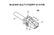
図1は従来のモジュラープラグ10A(以下、単にプラグという)を示しており、また図2はプラグ10Aが装着されるコネクタ1を示している。
FIG. 1 shows a conventional
このプラグ10Aは、プラグ本体11、ロック爪12、及びレバー部14等を有した構成とされている。プラグ本体11にはケーブル13が接続されており、このケーブル13はプラグ本体11内に配設されているコンタクトピン(図示せず)に電気的に接続されている。また、ロック爪12は、プラグ10Aがコネクタ1に装着された際、離脱を防止するものであり、レバー部14と一体的に形成されている。レバー部14は、図中矢印A1,A2方向に移動可能な構成とされており、ロックを解除する場合にはプラグ本体11とレバー部14を指で挟んで矢印A2方向に操作することにより、ロックが解除される構成とされている。
The
図2はコネクタ1を示しているが、同図に示す例では大量のアクセス側配線を収容するため、二つのコネクタ1を重ね合わせて使用する例を示している。
FIG. 2 shows the
コネクタ1は、横方向(図中矢印X1,X2方向)に列設された8個のコネクタ部8より構成される第1のコネクタ列設体3と、この第1のコネクタ列設体3の上部に配設されており、同じく横方向に列設された8個のコネクタ部8より構成される第2のコネクタ列設体4とを有している。更に、第2のコネクタ列設体4は第1のコネクタ列設体3の上部に積層された構成とされており、その上で各コネクタ列設体3,4をモールド樹脂9で樹脂封止した構成とされている。
The
また、各コネクタ部8はRJ−45コネクタに対応するよう構成されており、よって各コネクタ部8の背面側からは8本のリード6,7が延出される。具体的には、第1のコネクタ列設体3を構成するコネクタ部8からは第1のリード6が延出し、第2のコネクタ列設体4を構成するコネクタ部8からは第2のリード7が延出する。
Further, each connector portion 8 is configured to correspond to an RJ-45 connector, and therefore, eight leads 6 and 7 are extended from the back side of each connector portion 8. Specifically, the
このリード6,7は、水平方向に所定長さ延出された後、下方に向け折り曲げられた構成とされている。そして、折り曲げられたリード6,7の下端部は、プリント配線基板2に形成されたランドにはんだ付け接続される。
The
前記したように、コネクタ部8はRJ−45コネクタに対応するよう構成とされており、このコネクタ部8にはロック爪を有したプラグが装着される(図4参照)。よって、コネクタ1を複数積み重ねる場合には、各コネクタ間にはレバー部14を操作する操作空間を設ける必要があった。
As described above, the connector portion 8 is configured to correspond to the RJ-45 connector, and a plug having a lock claw is attached to the connector portion 8 (see FIG. 4). Therefore, when a plurality of
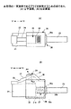
図3及び図4は、特許文献1に開示されたプラグ10Bを示している。なお、図3,4において図1に示したプラグ10Aと同一構成については同一符号を付している。プラグ10Bは、レバー部14の端部に被押圧部15が形成されると共に、プラグ本体11に可動部16が移動可能に配設された構成とされている。
3 and 4 show a
この構成とされたプラグ10Bでは、プラグ10Bをコネクタ1から離脱させる場合には、可動部16の両側部を指で把持すると共に可動部16を離脱方向(図4における左方向)に移動操作する。これにより、可動部16は被押圧部15と当接してこれを下方に向け付勢し、レバー部14は下方に向け押し下げられる。よって、ロック爪12によるコネクタ1との係止は解除され、プラグ10Bはコネクタ1から離脱可能な状態となる。
しかしながら、図1に示す従来のプラグ10Aでは、コネクタ1からプラグ10Aを離脱させる(引き抜きする)には、図5に示すように、レバー部14の操作を確保するため、前記のように上下一対のコネクタ1の間にロック爪14を操作する操作空間を設ける必要がある。このため、コネクタ全体としての高さ(図2に矢印h1で示す)が大きくなってしまい、薄型化を図ることができないという問題点があった。
However, in the
また、図4及び図5に示すプラグ10Bでは、図1の従来のように、プラグ本体11とレバー部14を上下方向から把持する必要はないものの、プラグ10Bをコネクタ1から離脱させるには、左右方向から可動部16を把持する必要がある。このため、プラグ10Bの構成では、図2(A)に矢印X1,X2で示す方向に対するコネクタ部8の実装密度が低下し、小型化を図ることができないという問題点があった。
Further, in the
本発明は上記の点に鑑みてなされたものであり、コネクタからの離脱時における操作性の向上を図ると共にコネクタの小型化・薄型化を図りうるモジュラープラグを提供することを目的とする。 The present invention has been made in view of the above points, and an object of the present invention is to provide a modular plug capable of improving the operability at the time of detachment from the connector and reducing the size and thickness of the connector.
上記の課題を解決するために本発明では、次に述べる各手段を講じたことを特徴とするものである。 In order to solve the above-described problems, the present invention is characterized by the following measures.
請求項1記載の発明は、コネクタに挿入脱されるプラグ本体と、挿入された該プラグ本体を前記コネクタに係止する係止爪と、操作されることにより前記係止爪による前記該プラグ本体と前記コネクタとの係止を解除させる操作レバーとを有するモジュラープラグにおいて、
前記挿入脱方向にスライド可能な構成で前記プラグ本体に配設されると共に、前記操作レバーと対向する位置に傾斜面が形成されたロック解除部材を設け、
該ロック解除部材をスライドさせるための操作部を、前記操作レバーと対向する位置の前記ロック解除部材の外側に形成し、
該ロック解除部材を前記挿入方向にスライドさせたとき、該スライドに伴い前記傾斜面が前記操作レバーを操作し、前記係止爪と前記コネクタとの係止を解除する構成としたことを特徴とするものである。
According to a first aspect of the present invention, there is provided a plug body inserted into and removed from a connector, a locking claw for locking the inserted plug body to the connector, and the plug body by the locking claw when operated. And a modular plug having an operation lever for releasing the engagement with the connector,
A lock release member having an inclined surface formed at a position facing the operation lever is provided in the plug body in a configuration that is slidable in the insertion / removal direction,
An operation portion for sliding the lock release member is formed outside the lock release member at a position facing the operation lever,
When the unlocking member is slid in the insertion direction, the inclined surface operates the operation lever along with the sliding to release the locking between the locking claw and the connector. To do.
また、請求項2記載の発明は、
請求項1記載のモジュラープラグにおいて、
前記ロック解除部材を、前記傾斜面が前記操作レバーから離間する方向に付勢する付勢部材を設けたことを特徴とするものである。
The invention according to
The modular plug according to
An urging member that urges the unlocking member in a direction in which the inclined surface is separated from the operation lever is provided.
また、請求項3記載の発明は、
請求項1または2記載のモジュラープラグにおいて、
前記プラグ本体に接続されるケーブルを内部に挿通する筒状部材を前記プラグ本体に配設し、該筒状部材に前記ロック解除部材の前記プラグ本体からの離脱を防止する離脱防止部を設けたことを特徴とするものである。
The invention according to
The modular plug according to
A cylindrical member for inserting a cable connected to the plug main body is disposed in the plug main body, and a release preventing portion for preventing the unlocking member from being detached from the plug main body is provided in the cylindrical member. It is characterized by this.
また、請求項4記載の発明は、
請求項1乃至3のいずれか1項に記載のモジュラープラグにおいて、
前記傾斜面を前記プラグ本体に突起の内部に形成すると共に、該突起を前記ロック解除部材を操作するときの操作ノブとして使用可能な構成としたことを特徴とするものである。
The invention according to claim 4
The modular plug according to any one of
The inclined surface is formed inside the protrusion on the plug body, and the protrusion can be used as an operation knob when operating the lock release member.
また、請求項5記載の発明は、
請求項1乃至4のいずれか1項に記載のモジュラープラグにおいて、
前記ロック解除部材は、前記プラグ本体の一部を収納する内部空間を有していることを特徴とするものである。
The invention according to claim 5
The modular plug according to any one of
The unlocking member has an internal space for housing a part of the plug body.
本発明によれば、ロック解除部材をスライド操作することにより傾斜面が操作レバーを操作し係止爪とコネクタとの係止を解除するため、従来のようにプラグ本体から斜めに延出した操作レバーを指でつかんでモジュラープラグのロックを解除する必要はなくなり、コネクタを接近させてモジュラープラグの搭載間隔を狭めたとしても、モジュラープラグの装着脱を確実に行うことができ、よって操作性を維持しつつ装着時におけるモジュラープラグ(コネクタ)の高密度化を図ることができる。 According to the present invention, the sliding operation of the unlocking member causes the inclined surface to operate the operation lever and unlock the locking claw and the connector. It is no longer necessary to unlock the modular plug by grasping the lever with your finger, and even if the modular plug mounting interval is narrowed by bringing the connector closer, the modular plug can be securely attached and detached, thus improving operability. It is possible to increase the density of the modular plug (connector) during mounting while maintaining.
また、コネクタからモジュラープラグを離脱させるには、ロック解除部材を挿入方向にスライドさせつつ、モジュラープラグをコネクタから引き抜く必要があり、よってモジュラープラグをコネクタから誤って抜いてしまうことを防止でき、装着時におけるモジュラープラグの安全性を高めることができる。 Also, in order to remove the modular plug from the connector, it is necessary to pull the modular plug out of the connector while sliding the unlocking member in the insertion direction. The safety of the modular plug at the time can be improved.
次に、本発明を実施するための最良の形態について図面と共に説明する。 Next, the best mode for carrying out the present invention will be described with reference to the drawings.
図6乃至図8は、本発明の一実施例であるモジュラープラグ20(以下、単にプラグという)を示している。なお、プラグ20が装着脱されるコネクタは、図1乃至図5に示したものと同一構成であるため、同一符号を付して説明するものとする。
6 to 8 show a modular plug 20 (hereinafter simply referred to as a plug) according to an embodiment of the present invention. The connector to which the
プラグ20は、大略するとプラグ本体21、ロック爪22、レバー部24、及びロック解除部材25等により構成されている。このプラグ20は、RJ−45の規格に対応したものである。
The
プラグ本体21は樹脂成形されており、内部にコネクタ1と電気的に接続するコンタクト(図示せず)が配設されている。また、プラグ本体21にはケーブル23が接続されており、このケーブル23はコンタクトピンに電気的に接続されている。具体的には、プラグ本体21の背面には筒状部材であるスリーブ26が固定されており、このスリーブ26の内部を挿通することより、ケーブル23はプラグ本体21内のコンタクトに接続される構成とされている。
The plug
ロック爪22は、プラグ20がコネクタ1のコネクタ部8に装着された際、コネクタ部8に形成されている係合部(図示せず)と係合する構成とされている。ロック爪22がコネクタ部8の係合部と係合することにより、プラグ20はコネクタ部8に係止(ロック)される。このように、ロック爪22によりプラグ20がコネクタ部8に係止されることにより、装着状態にあるプラグ20に対し引き抜き方向(図中矢印Y2方向)の外力が作用しても、プラグ20がコネクタ1から離脱するのを防止することができる。このロック爪22は、レバー部24と一体的に形成されている。
The
レバー部24はプラグ本体21と一体的に形成さており、プラグ本体21に対して斜め上方に向け延出した構成とされている。前記したロック爪22は、レバー部24のプラグ本体21に近い位置に一体的に形成されている。このレバー部24は、図中矢印A1,A2方向に弾性的に移動可能な構成とされている。よって、レバー部24に一体的に形成されているロック爪22も、レバー部24の移動に伴い移動する。
The
前記したロック爪22とコネクタ部8の係合部との係合は、レバー部24の弾性力によりロック爪22がコネクタ部8の係合部に押圧されることにより行われる。また、後述するようにレバー部24が弾性付勢力に抗して矢印A2方向に操作されると、ロック爪22とコネクタ部8の係合部との係合は解除され、よってプラグ20はコネクタ部8から離脱(引き抜き)可能な状態となる。
The engagement between the
続いて、ロック解除部材25について説明する。ロック解除部材25は樹脂成形されたものであり、解除部本体28、操作突起29、操作部30、及び内部空間32等を一体的に形成した構成とされている。
Next, the
解除部本体28は、内部に内部空間32(図7(B)参照)が形成されており、この内部空間32内に前記したプラグ本体21が挿入できる構成となっている。また、解除部本体28の背面にはスリーブ26が挿通する挿通孔28aが形成されている。これにより、ロック解除部材25は、プラグ本体21に対してプラグ20のコネクタ1への挿入方向(図中、矢印Y1方向)及びコネクタ1からの離脱方向(図中、矢印Y2方向)にスリーブ26及び内部空間32に案内されてスライド可能な構成となっている。
The release portion
また、図7(B)に示すように、プラグ本体21の外背面21aと、ロック解除部材25の内背面28bとの間には、コイルバネ27が配設されている。このコイルバネ27は、プラグ本体21とロック解除部材25とを相対的に離間させるように弾性力を付勢する構成とされている。しかしながら、スリーブ26の矢印Y2方向端部には鍔部26aが形成されているため、解除部本体28の背面は鍔部26aと当接することによりプラグ本体21からの離脱が防止されている。
As shown in FIG. 7B, a
操作突起29は、解除部本体28の上面に形成されている。具体的には、プラグ本体21においてレバー部24が形成されている面と対応する面に、操作突起29は形成されている。この操作突起29の内部は空間部33が形成されており、図7(B)及び図8に示すように操作突起29の内壁には傾斜面31が形成されている。更に、操作突起29の図中Y2方向部分には、後述するプラグ20をコネクタ1から離脱する(引き抜く)時に操作される操作部30が形成されている。
The
前記したレバー部24は、操作突起29内の空間部33内に位置するよう構成されている(図7(B)及び図8参照)。また、レバー部24は、操作突起29内に形成されている傾斜面31と対向するよう構成されている。更に、コイルバネ27は、前記したようにプラグ本体21とロック解除部材25とを相対的に離間させるように弾性力を付勢している。換言すると、コイルバネ27は、ロック解除部材25を傾斜面31がレバー部24から離間する方向に弾性力を付勢している。
The above-described
そして、図7(B)及び図8(A)に示すように、ロック解除部材25が鍔部26aと当接した状態(Y2方向に変位した状態)で、レバー部24の先端部が傾斜面31の上端部と対向するよう構成されている。上記構成とされた操作突起29は、その突出量が小さくなるよう構成されている。
Then, as shown in FIGS. 7B and 8A, the tip of the
具体的には、操作突起29の天板部29aの厚さは、機械的強度を維持しうる範囲で薄く設定された構成とされている。これにより、操作突起29の突出高さは、レバー部24の高さと略等しい(若干高い)構成となり、操作突起29を設けてもプラグ20の高さ(図8に矢印Z1,Z2で示す方向の高さ)が従来に比べて大きく高くなるようなことはない。
Specifically, the thickness of the
続いて、上記構成とされたプラグ20の動作について説明する。
Next, the operation of the
プラグ20をコネクタ1に装着する場合は、図9に示す状態よりプラグ20をコネクタ1のコネクタ部8に向け挿入する。具体的には、ロック解除部材25を図中矢印Y1方向に押圧操作する。
When the
前記したように、コイルバネ27が設けられることによりプラグ本体21とロック解除部材25は離間する方向に弾性付勢されているため、ロック解除部材25をY1方向に押圧操作することによりプラグ本体21もY1方向に移動し、よってプラグ20はコネクタ部8に装着される。この装着状態において、ロック爪22はコネクタ部8に形成された係合部と係合し、よってプラグ20はコネクタ1に係止される。
As described above, since the
次に、コネクタ部8に装着されているプラグ20を離脱させる(引き抜く)操作について説明する。プラグ20をコネクタ部8から離脱させるには、ロック解除部材25の操作部30をコイルバネ27の弾性力に抗して矢印Y1方向に押圧操作する。
Next, an operation of detaching (pulling out) the
プラグ20がコネクタ1に装着された状態では、プラグ本体21はコネクタ部8に係止(固定)されている。このため、操作部30をY1方向に押圧操作することにより、ロック解除部材25はプラグ本体21上を矢印Y1方向に向けスライド(移動)する。この際、本実施例では、プラグ本体21から突出した操作突起29をロック解除部材25を操作するときの操作ノブとして使用している。このため、操作突起29と別個に操作ノブを形成する構成に比べ、プラグ20の構成の簡単化を図ることができる。
When the
一方、前記のようにレバー部24はプラグ本体21に一体的に形成された構成であるため、ロック解除部材25がY1方向に移動を開始することにより、操作突起29に形成された傾斜面31も図7(B)及び図8(A)に示す位置からロック解除部材25に近接する方向(Y1方向)に移動を開始する。
On the other hand, since the
傾斜面31(ロック解除部材25)のY1方向の移動に伴い、傾斜面31はレバー部24の先端部と係合し、更に傾斜面31がY1方向に移動することにより、レバー部24は傾斜面31に付勢されて矢印A2方向に移動する。そして図8(B)に示すように、レバー部24はプラグ本体21の上面と略平行な位置まで移動し、よってレバー部24に一体的に形成されているロック爪22はコネクタ部8の係合部から離脱する。
As the inclined surface 31 (unlock member 25) moves in the Y1 direction, the
これにより、ロック爪22によるプラグ20をコネクタ1に固定するロック(係止)は解除される。続いて、プラグ20を引き抜くことにより、プラグ20はコネクタ1から離脱する。なお、プラグ20がコネクタ1から離脱すると、プラグ本体21はコイルバネ27の弾性復元力によりロック解除部材25に対してY1方向に移動し図7及び図8(A)に示す元の状態に戻る。
Thereby, the lock (locking) for fixing the
このように、本実施例に係るプラグ20は、単に操作部30(ロック解除部材25)を挿入方向(Y1方向)にスライド動作させるだけで、プラグ20をコネクタ1から離脱させることができる。よって、従来のプラグ10A(図1参照)のように、離脱時にプラグ本体11とレバー部14を上下方向から指で挟みレバー部14をA2方向に移動させる必要はなくなる。また、従来のプラグ10B(図3,図4参照)のように、離脱時に可動部16を左右方向から指で挟み移動させる必要はなくなる。
As described above, the
よって、本実施例に係るプラグ20を用いることにより、コネクタ1においてコネクタ部8を接近させてプラグ20の搭載間隔を狭めたとしても、プラグ20の装着脱を確実に行うことができ、よって操作性を維持しつつ装着時におけるプラグ20(コネクタ部8)の高密度化を図ることができる。
Therefore, by using the
また、コネクタ1からプラグ20を離脱させるには、ロック解除部材25を挿入方向(Y1方向)にスライド操作させ、次にプラグ20をコネクタ1から離脱方向(Y2方向)に引き抜く必要がある。このように2方向の操作によりはじめてプラグ20はコネクタ1から離脱可能となるため、誤ってプラグ20をコネクタ1から離脱させる事故を防止することができる。
Further, in order to detach the
図10乃至図13は、本実施例に係るプラグ20を適用したプラグ装着構造の効果を説明するための図である。
10 to 13 are views for explaining the effect of the plug mounting structure to which the
図10(A),(B)は、プラグ20を装着した状態のコネクタ1の正面図である。図10(A)は、上下1対のコネクタ1が積層された構成を示しており、上下のコネクタ1のコネクタ部8が近接した構成とされている。しかしながら、本実施例に係るプラグ20では、操作突起29を押圧操作しうる間隙があれば充分であり、操作者の指が入るスペースを設ける必要はなく、よって上下のコネクタ部8を近接させることが可能となる。また、図10(B)に示すように、上下のコネクタ1で、コネクタ部8の配設位置が半ピッチずれるよう配置することにより、更に上下のコネクタ1の間隔を狭めることができ、コネクタ全体としての小型化・薄型化を図ることができる。
FIGS. 10A and 10B are front views of the
図11乃至図13は、本実施例に係るプラグ20を適用することによりコネクタユニットの小型化を図ることができることを従来のプラグ10Aを適用したコネクタユニットと比較して示す図である。なお、図11乃至図13において(A)で示す図は従来のプラグ10Aに対応したプラグインユニット45を示しており、(B)で示す図は本実施例に係るプラグ20に対応したプラグインユニット40A〜40Cを示している。
11 to 13 are views showing that the connector unit can be miniaturized by applying the
図11(B)は、上下のコネクタ1を揃えて積層することにより、コネクタ部8が上下に対向するようにしたプラグインユニット40Aを示している。この場合、従来上下のコネクタ1の離間寸法が図中矢印H必要であったものが、プラグ20に対応しうる構成とすることにより、図中矢印h1で示す離間寸法まで狭くすることが可能となった。
FIG. 11B shows a plug-in
また、図12(B)は、上下のコネクタ1を左右にずらして積層することにより、コネクタ部8が上下に反ピッチずれて位置するようにしたプラグインユニット40Bを示している。この構成とした場合には、上下のコネクタ1間の離間寸法を略無くすることができる。
FIG. 12B shows a plug-in unit 40B in which the upper and
更に、図13(B)は、上部に列設されたコネクタ部8Aと、下部に列設されたコネクタ部8Bを反ピッチずらした構成とされたコネクタ1Aを上下に揃えて積層した構成のプラグインユニット40Cを示している。この場合、従来上下のコネクタ1の離間寸法が図中矢印H必要であったものが、プラグインユニット40Cとすることにより、上部のコネクタ1Aのコネクタ部8Bと下部のコネクタ1Aのコネクタ部8Bとの離間距離を図中矢印h2で示す離間寸法まで狭くすることが可能となった。このように、本発明に係るプラグ20を用いることにより、プラグインユニット40A〜40Cの小型化を図ることが可能となる。
Further, FIG. 13B shows a plug having a configuration in which the connector portion 8A arranged in the upper portion and the connector portion 8A arranged in the lower portion are shifted by an anti-pitch and are stacked vertically aligned. The in-unit 40C is shown. In this case, the distance between the upper and
以上の説明に関し、更に以下の項を開示する。
(付記1)
コネクタに挿入脱されるプラグ本体と、挿入された該プラグ本体を前記コネクタに係止する係止爪と、操作されることにより前記係止爪による前記該プラグ本体と前記コネクタとの係止を解除させる操作レバーとを有するモジュラープラグにおいて、
前記挿入脱方向にスライド可能な構成で前記プラグ本体に配設されると共に、前記操作レバーと対向する位置に傾斜面が形成されたロック解除部材を設け、
該ロック解除部材を前記挿入方向にスライドさせたとき、該スライドに伴い前記傾斜面が前記操作レバーを操作し、前記係止爪と前記コネクタとの係止を解除する構成としたことを特徴とするモジュラープラグ。
(付記2)
前記ロック解除部材を、前記傾斜面が前記操作レバーから離間する方向に付勢する付勢部材を設けたことを特徴とする付記1記載のモジュラープラグ。
(付記3)
前記プラグ本体に接続されるケーブルを内部に挿通する筒状部材を前記プラグ本体に配設し、該筒状部材に前記ロック解除部材の前記プラグ本体からの離脱を防止する離脱防止部を設けたことを特徴とする付記1または2記載のモジュラープラグ。
(付記4)
前記傾斜面を前記プラグ本体に突起の内部に形成すると共に、該突起を前記ロック解除部材を操作するときの操作ノブとして使用可能な構成としたことを特徴とする付記1乃至3のいずれか1項に記載のモジュラープラグ。
(付記5)
前記ロック解除部材は、前記プラグ本体の一部を収納する内部空間を有していることを特徴とする付記1乃至4のいずれか1項に記載のモジュラープラグ。
(付記6)
複数のコネクタ部が列設されたコネクタ列設体を有する複数段積層してなるコネクタと、
前記コネクタ部に挿入脱されるプラグ本体と、挿入された該プラグ本体を前記コネクタ部に係止する係止爪と、操作されることにより前記係止爪による前記該プラグ本体と前記コネクタ部との係止を解除させる操作レバーとを有するモジュラープラグとにより構成されるプラグ装着構造において、
モジュラープラグは、
前記コネクタへの挿入方向及び離脱方向にスライド可能な構成とされると共に、前記操作レバーと対向する位置に傾斜面が形成されたロック解除部材を有し、
該ロック解除部材を前記挿入方向にスライドさせたとき、該スライドに伴い前記傾斜面が前記操作レバーを操作し、前記係止爪と前記コネクタ部との係止が解除されることを特徴とするプラグ装着構造
(付記7)
前記ロック解除部材を、前記傾斜面が前記操作レバーから離間する方向に付勢する付勢部材を設けたことを特徴とする付記6記載のプラグ装着構造。
(付記8)
前記プラグ本体に接続されるケーブルを内部に挿通する筒状部材を前記プラグ本体に配設し、該筒状部材に前記ロック解除部材の前記プラグ本体からの離脱を防止する離脱防止部を設けたことを特徴とする付記6または7記載のプラグ装着構造。
(付記9)
前記傾斜面を前記プラグ本体に突起の内部に形成すると共に、該突起を前記ロック解除部材を操作するときの操作ノブとして使用可能な構成としたことを特徴とする付記6乃至8のいずれか1項に記載のプラグ装着構造。
(付記10)
前記ロック解除部材は、前記プラグ本体の一部を収納する内部空間を有していることを特徴とする付記6乃至9のいずれか1項に記載のプラグ装着構造。
(付記11)
下段に位置する前記コネクタ列設体の前記コネクタ部の位置と、その上段に位置する前記コネクタ列設体の前記コネクタ部の位置とをずらして配置したことを特徴とする付記6乃至10のいずれか1項に記載のプラグ装着構造。
(付記12)
前記コネクタ部は、RJ−45コネクタであることを特徴とする付記6乃至11のいずれか1項に記載のプラグ装着構造。
Regarding the above description, the following items are further disclosed.
(Appendix 1)
A plug main body inserted into and removed from the connector, a locking claw for locking the inserted plug main body to the connector, and the operation of locking the plug main body and the connector by the locking claw In a modular plug having an operating lever to be released,
A lock release member having an inclined surface formed at a position facing the operation lever is provided in the plug body in a configuration that is slidable in the insertion / removal direction,
When the unlocking member is slid in the insertion direction, the inclined surface operates the operation lever along with the sliding to release the locking between the locking claw and the connector. Modular plug to be used.
(Appendix 2)
2. The modular plug according to
(Appendix 3)
A cylindrical member for inserting a cable connected to the plug main body is disposed in the plug main body, and a release preventing portion for preventing the unlocking member from being detached from the plug main body is provided in the cylindrical member. The modular plug according to
(Appendix 4)
Any one of
(Appendix 5)
The modular plug according to any one of
(Appendix 6)
A connector formed by laminating a plurality of stages having a connector row structure in which a plurality of connector portions are arranged; and
A plug body inserted into and removed from the connector portion; a locking claw for locking the inserted plug body to the connector portion; and the plug body and the connector portion by the locking claw when operated. In a plug mounting structure constituted by a modular plug having an operation lever for releasing the locking of
The modular plug
It is configured to be slidable in the insertion direction and the withdrawal direction to the connector, and has a lock release member formed with an inclined surface at a position facing the operation lever.
When the lock release member is slid in the insertion direction, the inclined surface operates the operation lever along with the slide, and the engagement between the engagement claw and the connector portion is released. Plug mounting structure
(Appendix 7)
7. The plug mounting structure according to
(Appendix 8)
A cylindrical member for inserting a cable connected to the plug main body is disposed in the plug main body, and a release preventing portion for preventing the unlocking member from being detached from the plug main body is provided in the cylindrical member. The plug mounting structure according to
(Appendix 9)
Any one of
(Appendix 10)
10. The plug mounting structure according to any one of
(Appendix 11)
Any one of
(Appendix 12)
The plug mounting structure according to any one of
1 コネクタ1
8 コネクタ部
20 プラグ
21 プラグ本体
22 ロック爪
23 ケーブル
24 レバー部
25 ロック解除部材
26 スリーブ
27 コイルバネ
28 解除部本体
29 操作突起
30 操作部
31 傾斜面
32 内部空間
40A〜40C プラグインユニット
1
8
Claims (5)
前記挿入脱方向にスライド可能な構成で前記プラグ本体に配設されると共に、前記操作レバーと対向する位置に傾斜面が形成されたロック解除部材を設け、
該ロック解除部材をスライドさせるための操作部を、前記操作レバーと対向する位置の前記ロック解除部材の外側に形成し、
該ロック解除部材を前記挿入方向にスライドさせたとき、該スライドに伴い前記傾斜面が前記操作レバーを操作し、前記係止爪と前記コネクタとの係止を解除する構成としたことを特徴とするモジュラープラグ。 A plug main body inserted into and removed from the connector, a locking claw for locking the inserted plug main body to the connector, and the operation of locking the plug main body and the connector by the locking claw In a modular plug having an operating lever to be released,
A lock release member having an inclined surface formed at a position facing the operation lever is provided in the plug body in a configuration that is slidable in the insertion / removal direction,
An operation portion for sliding the lock release member is formed outside the lock release member at a position facing the operation lever,
When the unlocking member is slid in the insertion direction, the inclined surface operates the operation lever along with the sliding to release the locking between the locking claw and the connector. Modular plug to be used.
Priority Applications (3)
| Application Number | Priority Date | Filing Date | Title |
|---|---|---|---|
| JP2006177266A JP4832183B2 (en) | 2006-06-27 | 2006-06-27 | Modular plug |
| US11/585,903 US7465180B2 (en) | 2006-06-27 | 2006-10-25 | Modular plug and plug installation structure |
| CNB2006101484820A CN100533867C (en) | 2006-06-27 | 2006-11-17 | Modular plug and plug installation structure |
Applications Claiming Priority (1)
| Application Number | Priority Date | Filing Date | Title |
|---|---|---|---|
| JP2006177266A JP4832183B2 (en) | 2006-06-27 | 2006-06-27 | Modular plug |
Publications (2)
| Publication Number | Publication Date |
|---|---|
| JP2008010210A JP2008010210A (en) | 2008-01-17 |
| JP4832183B2 true JP4832183B2 (en) | 2011-12-07 |
Family
ID=38874070
Family Applications (1)
| Application Number | Title | Priority Date | Filing Date |
|---|---|---|---|
| JP2006177266A Expired - Fee Related JP4832183B2 (en) | 2006-06-27 | 2006-06-27 | Modular plug |
Country Status (3)
| Country | Link |
|---|---|
| US (1) | US7465180B2 (en) |
| JP (1) | JP4832183B2 (en) |
| CN (1) | CN100533867C (en) |
Families Citing this family (93)
| Publication number | Priority date | Publication date | Assignee | Title |
|---|---|---|---|---|
| US7806706B2 (en) * | 2007-07-03 | 2010-10-05 | Panduit Corp. | Plug locking assembly and system |
| EP2144100B1 (en) * | 2008-07-10 | 2012-03-28 | Sanwa Denki Kogyo Co., Ltd. | Optical Connector Plug |
| KR101185809B1 (en) | 2008-10-01 | 2012-10-02 | 후지쯔 가부시끼가이샤 | Connector, electronic apparatus, method for removing connector |
| US8408815B2 (en) * | 2009-06-18 | 2013-04-02 | Senko Advanced Components, Inc. | Optical fiber connector and adapter |
| US7972183B1 (en) * | 2010-03-19 | 2011-07-05 | Commscope, Inc. Of North Carolina | Sled that reduces the next variations between modular plugs |
| CN102201631A (en) * | 2010-03-26 | 2011-09-28 | 富士康(昆山)电脑接插件有限公司 | Electric connector component |
| US8025514B1 (en) | 2010-04-23 | 2011-09-27 | Leviton Manufacturing Co., Inc. | Shroud to prevent manipulation of a release mechanism of a plug |
| US8038456B1 (en) | 2010-04-23 | 2011-10-18 | Leviton Manufacturing Co., Inc | Tamper prevention system having a shroud to partially cover a release mechanism |
| CN102544903A (en) * | 2010-12-28 | 2012-07-04 | 鸿富锦精密工业(深圳)有限公司 | Auxiliary device for pulling out crystal head and crystal head combination |
| ES2402632B1 (en) | 2011-02-08 | 2014-05-14 | Tyco Electronics Raychem Bvba | RELEASE TONGUE FOR AN ELECTRICAL CONNECTOR AND ELECTRICAL CONNECTOR THAT INCLUDES SUCH RELEASE TONGUE |
| ES2395358B1 (en) | 2011-02-08 | 2014-04-25 | Tyco Electronics Corporation | SINGLE ACTION CONNECTOR |
| CN104040393B (en) | 2011-05-04 | 2017-12-08 | 西蒙公司 | The joints of optical fibre with reversing |
| JP5721536B2 (en) * | 2011-05-20 | 2015-05-20 | 矢崎総業株式会社 | Half-mating prevention connector |
| US9188747B2 (en) | 2011-05-23 | 2015-11-17 | Senko Advanced Components, Inc. | True one piece housing fiber optic adapter |
| CN102957027A (en) * | 2011-08-29 | 2013-03-06 | 鸿富锦精密工业(武汉)有限公司 | Connector |
| TWI425721B (en) * | 2011-09-08 | 2014-02-01 | Powertech Ind Co Ltd | Plug connector |
| CN103703631B (en) * | 2011-10-05 | 2017-02-15 | 扇港元器件有限公司 | Latching connector with remote release |
| JP5772603B2 (en) * | 2012-01-06 | 2015-09-02 | 富士通株式会社 | Switching hub device and connector lock release tool |
| CN103257407B (en) * | 2012-02-20 | 2015-11-25 | 泰科电子(上海)有限公司 | Connector and connector assembly |
| US8899845B2 (en) | 2012-05-15 | 2014-12-02 | Panduit Corp. | Fiber optic connector |
| US8974124B2 (en) | 2012-08-16 | 2015-03-10 | Senko Advanced Components, Inc. | Fiber optic connector |
| CN103682820A (en) * | 2012-08-30 | 2014-03-26 | 鸿富锦精密工业(深圳)有限公司 | Electronic device and connector pulling auxiliary part |
| US8979569B2 (en) * | 2013-03-15 | 2015-03-17 | Ortronics, Inc. | Modular connectors and associated systems and methods |
| CN104112943A (en) * | 2013-04-17 | 2014-10-22 | 鸿富锦精密电子(天津)有限公司 | Assisting connector plugging and pulling device |
| US9268103B2 (en) | 2013-05-10 | 2016-02-23 | Senko Advanced Components, Inc. | Interlockable fiber optic connector adaptors |
| US9360649B2 (en) | 2013-05-22 | 2016-06-07 | Senko Advanced Components, Inc. | Cable guide for fiber optic cables |
| CN203326271U (en) * | 2013-06-20 | 2013-12-04 | 宁波卓新通讯接插件有限公司 | Network connector which can be pulled out easily |
| US9048580B2 (en) * | 2013-09-17 | 2015-06-02 | Ningbo Excellence Communicated Connector Co., Ltd. | Easy-pull male network connector and tool combination |
| US9618703B2 (en) | 2013-10-03 | 2017-04-11 | Senko Advanced Components, Inc. | Connector housing for securing an optical cable and methods of use and manufacture thereof |
| US9477049B2 (en) | 2013-12-20 | 2016-10-25 | Senko Advanced Components, Inc. | Lockable connectors and connection assemblies |
| EP3907541B1 (en) | 2014-01-13 | 2023-12-27 | CommScope Telecommunications (Shanghai) Co. Ltd. | Fiber optic connector |
| US9535230B2 (en) | 2014-01-31 | 2017-01-03 | Senko Advanced Components, Inc. | Integrated fiber optic cable fan-out connector |
| US9297964B2 (en) | 2014-04-18 | 2016-03-29 | Senko Advanced Components, Inc. | Optical fiber connector assembly |
| US9274287B2 (en) | 2014-05-13 | 2016-03-01 | Senko Advanced Components, Inc. | Optical fiber connector and ferrule |
| US9618702B2 (en) | 2014-06-09 | 2017-04-11 | Senko Advanced Components, Inc. | Reduced-profile data transmission element connectors, adapters, and connection assemblies thereof |
| US9401577B2 (en) * | 2014-08-01 | 2016-07-26 | Echostar Technologies L.L.C. | RJ-45 insertion and extraction tool |
| US10014627B2 (en) * | 2014-08-20 | 2018-07-03 | Volex Plc | Electrical connector with unlocking sleeve |
| US9599778B2 (en) | 2014-10-22 | 2017-03-21 | Senko Advanced Components, Inc. | Latching connector with remote release |
| US9494745B2 (en) | 2015-01-16 | 2016-11-15 | Senko Advanced Components, Inc. | Sealable communication cable connection assemblies |
| US9658409B2 (en) | 2015-03-03 | 2017-05-23 | Senko Advanced Components, Inc. | Optical fiber connector with changeable polarity |
| US9684139B2 (en) | 2015-05-29 | 2017-06-20 | Senko Advanced Components, Inc. | Optical fiber connector with changeable gender |
| US9726830B1 (en) | 2016-06-28 | 2017-08-08 | Senko Advanced Components, Inc. | Connector and adapter system for two-fiber mechanical transfer type ferrule |
| KR102588303B1 (en) * | 2016-10-17 | 2023-10-11 | 엘에스전선 주식회사 | Connector and patch cord having the same |
| US10078188B1 (en) | 2016-12-05 | 2018-09-18 | Senko Advanced Components, Inc. | Springless push/pull fiber optic connector |
| US10228521B2 (en) | 2016-12-05 | 2019-03-12 | Senko Advanced Components, Inc. | Narrow width adapters and connectors with modular latching arm |
| US10444444B2 (en) | 2017-01-30 | 2019-10-15 | Senko Advanced Components, Inc. | Remote release tab connector assembly |
| US10725248B2 (en) | 2017-01-30 | 2020-07-28 | Senko Advanced Components, Inc. | Fiber optic receptacle with integrated device therein incorporating a behind-the-wall fiber optic receptacle |
| US10185100B2 (en) | 2017-01-30 | 2019-01-22 | Senko Advanced Components, Inc | Modular connector and adapter assembly using a removable anchor device |
| EP3574356A4 (en) | 2017-01-30 | 2020-08-19 | Senko Advanced Components Inc. | Optical connectors with reversible polarity |
| US10416394B2 (en) | 2017-01-30 | 2019-09-17 | Senko Advanced Components, Inc. | Fiber optic receptacle with integrated device therein |
| US11333836B2 (en) | 2017-01-30 | 2022-05-17 | Senko Advanced Components, Inc. | Adapter for optical connectors |
| US9989712B1 (en) | 2017-03-20 | 2018-06-05 | Senko Advanced Components, Inc | MPO connector assembly with push-pull tab |
| US10989884B2 (en) | 2017-04-07 | 2021-04-27 | Senko Advanced Components, Inc. | Behind the wall optical connector with reduced components |
| US10359583B2 (en) | 2017-04-07 | 2019-07-23 | Senko Advanced Components, Inc. | Behind the wall optical connector with reduced components |
| US10754098B2 (en) | 2017-04-07 | 2020-08-25 | Senko Advanced Components, Inc. | Behind the wall optical connector with reduced components |
| US10209461B2 (en) | 2017-04-07 | 2019-02-19 | Senko Advanced Components | Behind the wall optical connector with reduced components |
| US10718910B2 (en) | 2017-05-03 | 2020-07-21 | Senko Advanced Components, Inc | Field terminated ruggedized fiber optic connector system |
| US10401576B2 (en) | 2017-05-10 | 2019-09-03 | Senko Advanced Components, Inc. | MPO micro-latch-lock connector |
| US10146016B1 (en) | 2017-05-10 | 2018-12-04 | Senko Advanced Components, Inc | MPO micro-latchlock connector |
| US10520686B2 (en) | 2017-05-18 | 2019-12-31 | Senko Advanced Components, Inc. | Optical connector with one-piece body |
| US11215767B2 (en) | 2017-06-07 | 2022-01-04 | Commscope Technologies Llc | Fiber optic adapter and cassette |
| US10359576B2 (en) | 2017-06-15 | 2019-07-23 | Senko Advanced Components, Inc. | SC low profile connector with optional boot |
| US11822133B2 (en) | 2017-07-14 | 2023-11-21 | Senko Advanced Components, Inc. | Ultra-small form factor optical connector and adapter |
| US10281669B2 (en) | 2017-07-14 | 2019-05-07 | Senko Advance Components, Inc. | Ultra-small form factor optical connectors |
| US10705300B2 (en) | 2017-07-14 | 2020-07-07 | Senko Advanced Components, Inc. | Small form factor fiber optic connector with multi-purpose boot assembly |
| US10718911B2 (en) | 2017-08-24 | 2020-07-21 | Senko Advanced Components, Inc. | Ultra-small form factor optical connectors using a push-pull boot receptacle release |
| US10641972B2 (en) | 2017-08-17 | 2020-05-05 | Senko Advanced Components, Inc | Anti-jam alignment sleeve holder or connector housing for a ferrule assembly |
| EP3682277A4 (en) | 2017-09-15 | 2021-06-02 | Commscope Technologies LLC | Fiber optic connector with boot-integrated release and related assemblies |
| US10444442B2 (en) | 2017-11-03 | 2019-10-15 | Senko Advanced Components, Inc. | MPO optical fiber connector |
| US10830963B2 (en) | 2017-11-17 | 2020-11-10 | Commscope Technologies Llc | Fiber optic connector locking feature |
| US11002923B2 (en) | 2017-11-21 | 2021-05-11 | Senko Advanced Components, Inc. | Fiber optic connector with cable boot release having a two-piece clip assembly |
| US10678000B2 (en) | 2018-01-05 | 2020-06-09 | Senko Advanced Components, Inc. | Pull rod and alignment key for a fiber optic connector and adapter |
| WO2019183070A2 (en) | 2018-03-19 | 2019-09-26 | Senko Advanced Components, Inc. | Removal tool for removing a plural of micro optical connectors from an adapter interface |
| US11041993B2 (en) | 2018-04-19 | 2021-06-22 | Senko Advanced Components, Inc. | Fiber optic adapter with removable insert for polarity change and removal tool for the same |
| US10921528B2 (en) | 2018-06-07 | 2021-02-16 | Senko Advanced Components, Inc. | Dual spring multi-fiber optic connector |
| CN112088327A (en) | 2018-07-15 | 2020-12-15 | 扇港元器件股份有限公司 | Ultra-small optical connector and adapter |
| US10444441B1 (en) | 2018-08-10 | 2019-10-15 | Senko Advanced Components, Inc. | Pivotable housing for a fiber optic connector |
| US11073664B2 (en) | 2018-08-13 | 2021-07-27 | Senko Advanced Components, Inc. | Cable boot assembly for releasing fiber optic connector from a receptacle |
| US10921531B2 (en) | 2018-09-12 | 2021-02-16 | Senko Advanced Components, Inc. | LC type connector with push/pull assembly for releasing connector from a receptacle using a cable boot |
| WO2020055440A1 (en) | 2018-09-12 | 2020-03-19 | Senko Advanced Componetns, Inc. | Lc type connector with clip-on push/pull tab for releasing connector from a receptacle using a cable boot |
| US10921530B2 (en) | 2018-09-12 | 2021-02-16 | Senko Advanced Components, Inc. | LC type connector with push/pull assembly for releasing connector from a receptacle using a cable boot |
| US11806831B2 (en) | 2018-11-21 | 2023-11-07 | Senko Advanced Components, Inc. | Fixture and method for polishing fiber optic connector ferrules |
| US11175464B2 (en) | 2018-11-25 | 2021-11-16 | Senko Advanced Components, Inc. | Open ended spring body for use in an optical fiber connector |
| US11689247B2 (en) | 2019-01-16 | 2023-06-27 | Mertek Industries, Llc | Patch cord including wireless components |
| CN113631976B (en) | 2019-03-28 | 2023-06-09 | 扇港元器件有限公司 | Fiber optic adapter assembly |
| US11340406B2 (en) | 2019-04-19 | 2022-05-24 | Senko Advanced Components, Inc. | Small form factor fiber optic connector with resilient latching mechanism for securing within a hook-less receptacle |
| CN114026480B (en) | 2019-06-13 | 2023-05-26 | 扇港元器件有限公司 | Lever actuated latch arm for releasing fiber optic connectors from receptacle ports and method of use |
| US11467354B2 (en) | 2019-07-23 | 2022-10-11 | Senko Advanced Components, Inc. | Ultra-small form factor receptacle for receiving a fiber optic connector opposing a ferrule assembly |
| US11353664B1 (en) | 2019-08-21 | 2022-06-07 | Senko Advanced Components, Inc. | Fiber optic connector |
| WO2021097304A1 (en) | 2019-11-13 | 2021-05-20 | Senko Advanced Components, Inc. | Fiber optic connector |
| JP7044814B2 (en) * | 2020-02-10 | 2022-03-30 | 矢崎総業株式会社 | Electronic unit |
| US11646532B1 (en) * | 2021-11-03 | 2023-05-09 | Dell Products L.P. | Connector release system |
| JP7322260B1 (en) | 2022-08-25 | 2023-08-07 | 真弓 ▲高▼倉 | connector |
Family Cites Families (12)
| Publication number | Priority date | Publication date | Assignee | Title |
|---|---|---|---|---|
| JPS63150874A (en) * | 1986-12-15 | 1988-06-23 | 松下電工株式会社 | Adaptor for modular plug operation |
| JPS63184274A (en) * | 1987-01-27 | 1988-07-29 | 松下電工株式会社 | Adaptor for modular plug |
| JPS63184271A (en) * | 1987-01-27 | 1988-07-29 | 松下電工株式会社 | Modular plug |
| US5462457A (en) * | 1994-09-22 | 1995-10-31 | The Whitaker Corporation | Overmold strain relief and snag prevention feature |
| US5494457A (en) * | 1994-09-28 | 1996-02-27 | Acs Industries, Inc. | Snagless strain relief |
| JPH11126653A (en) | 1997-10-23 | 1999-05-11 | Nec Eng Ltd | Modular plug and lock claw break preventing mechanism used for it |
| US6250949B1 (en) * | 1998-12-16 | 2001-06-26 | Lucent Technologies Inc. | Communication cable terminating plug |
| US6238251B1 (en) * | 1998-12-29 | 2001-05-29 | Lucent Technologies Inc. | Patch panel with patch cord plug keyway |
| JP2001326026A (en) * | 2000-05-15 | 2001-11-22 | Nec Gumma Ltd | Connector detaching structure |
| US6371787B1 (en) * | 2001-03-07 | 2002-04-16 | International Business Machines Corporation | Pull-to-release type latch mechanism for removable small form factor electronic modules |
| US7063554B2 (en) * | 2003-01-09 | 2006-06-20 | International Business Machines Corporation | Modular connector anti-snag retrofit |
| US7052186B1 (en) * | 2005-06-08 | 2006-05-30 | Itt Manufacturing Enterprises, Inc. | Secondary latch sleeve for connector connections |
-
2006
- 2006-06-27 JP JP2006177266A patent/JP4832183B2/en not_active Expired - Fee Related
- 2006-10-25 US US11/585,903 patent/US7465180B2/en not_active Expired - Fee Related
- 2006-11-17 CN CNB2006101484820A patent/CN100533867C/en not_active Expired - Fee Related
Also Published As
| Publication number | Publication date |
|---|---|
| US7465180B2 (en) | 2008-12-16 |
| US20070298636A1 (en) | 2007-12-27 |
| CN101098062A (en) | 2008-01-02 |
| CN100533867C (en) | 2009-08-26 |
| JP2008010210A (en) | 2008-01-17 |
Similar Documents
| Publication | Publication Date | Title |
|---|---|---|
| JP4832183B2 (en) | Modular plug | |
| US7901226B2 (en) | Connector of a simple structure having a locking mechanism | |
| JP5298227B1 (en) | connector | |
| JPH1197111A (en) | Half-fit preventive connector | |
| CN106856282B (en) | Connector with a locking member | |
| JP4527675B2 (en) | IC card connector | |
| KR20150003378A (en) | Connector for flat cable | |
| TWI479746B (en) | Connector | |
| JP5811341B2 (en) | Connector device | |
| JP5825472B2 (en) | Connector device | |
| JP5404024B2 (en) | Terminal block fixing structure and control equipment | |
| US8944700B2 (en) | Connector | |
| JP5909586B1 (en) | Electrical connector | |
| JP2009104985A (en) | Connector with coming-off preventing mechanism | |
| JPH09245888A (en) | Connector structure | |
| JP2014179300A (en) | Connector device | |
| JP5839197B2 (en) | Wiring board connecting device | |
| JP5842677B2 (en) | Connector device | |
| CN114270632A (en) | Connector and electronic device | |
| WO2021024602A1 (en) | Plug connector and connector set having same, and method for removing connector set | |
| WO2023090114A1 (en) | Board connector device | |
| JP2011134666A (en) | Electrical connector, electrical connector assembly | |
| JP5839196B2 (en) | Connector device | |
| WO2015002144A1 (en) | Connection structure for flat circuit body and connector | |
| JP5854272B2 (en) | Connector device |
Legal Events
| Date | Code | Title | Description |
|---|---|---|---|
| A621 | Written request for application examination |
Free format text: JAPANESE INTERMEDIATE CODE: A621 Effective date: 20090309 |
|
| A977 | Report on retrieval |
Free format text: JAPANESE INTERMEDIATE CODE: A971007 Effective date: 20101227 |
|
| A131 | Notification of reasons for refusal |
Free format text: JAPANESE INTERMEDIATE CODE: A131 Effective date: 20110118 |
|
| A521 | Written amendment |
Free format text: JAPANESE INTERMEDIATE CODE: A523 Effective date: 20110322 |
|
| TRDD | Decision of grant or rejection written | ||
| A01 | Written decision to grant a patent or to grant a registration (utility model) |
Free format text: JAPANESE INTERMEDIATE CODE: A01 Effective date: 20110823 |
|
| A01 | Written decision to grant a patent or to grant a registration (utility model) |
Free format text: JAPANESE INTERMEDIATE CODE: A01 |
|
| A61 | First payment of annual fees (during grant procedure) |
Free format text: JAPANESE INTERMEDIATE CODE: A61 Effective date: 20110920 |
|
| R150 | Certificate of patent or registration of utility model |
Free format text: JAPANESE INTERMEDIATE CODE: R150 |
|
| FPAY | Renewal fee payment (event date is renewal date of database) |
Free format text: PAYMENT UNTIL: 20140930 Year of fee payment: 3 |
|
| LAPS | Cancellation because of no payment of annual fees |