EP2337137A2 - Rechargeable battery - Google Patents
Rechargeable battery Download PDFInfo
- Publication number
- EP2337137A2 EP2337137A2 EP10251710A EP10251710A EP2337137A2 EP 2337137 A2 EP2337137 A2 EP 2337137A2 EP 10251710 A EP10251710 A EP 10251710A EP 10251710 A EP10251710 A EP 10251710A EP 2337137 A2 EP2337137 A2 EP 2337137A2
- Authority
- EP
- European Patent Office
- Prior art keywords
- electrode
- plate
- secondary battery
- collector plate
- assemblies
- Prior art date
- Legal status (The legal status is an assumption and is not a legal conclusion. Google has not performed a legal analysis and makes no representation as to the accuracy of the status listed.)
- Granted
Links
Images


Classifications
-
- H—ELECTRICITY
- H01—ELECTRIC ELEMENTS
- H01M—PROCESSES OR MEANS, e.g. BATTERIES, FOR THE DIRECT CONVERSION OF CHEMICAL ENERGY INTO ELECTRICAL ENERGY
- H01M4/00—Electrodes
- H01M4/02—Electrodes composed of, or comprising, active material
- H01M4/64—Carriers or collectors
- H01M4/70—Carriers or collectors characterised by shape or form
- H01M4/75—Wires, rods or strips
-
- H—ELECTRICITY
- H01—ELECTRIC ELEMENTS
- H01M—PROCESSES OR MEANS, e.g. BATTERIES, FOR THE DIRECT CONVERSION OF CHEMICAL ENERGY INTO ELECTRICAL ENERGY
- H01M10/00—Secondary cells; Manufacture thereof
- H01M10/04—Construction or manufacture in general
- H01M10/0431—Cells with wound or folded electrodes
-
- H—ELECTRICITY
- H01—ELECTRIC ELEMENTS
- H01M—PROCESSES OR MEANS, e.g. BATTERIES, FOR THE DIRECT CONVERSION OF CHEMICAL ENERGY INTO ELECTRICAL ENERGY
- H01M10/00—Secondary cells; Manufacture thereof
- H01M10/05—Accumulators with non-aqueous electrolyte
- H01M10/052—Li-accumulators
-
- H—ELECTRICITY
- H01—ELECTRIC ELEMENTS
- H01M—PROCESSES OR MEANS, e.g. BATTERIES, FOR THE DIRECT CONVERSION OF CHEMICAL ENERGY INTO ELECTRICAL ENERGY
- H01M10/00—Secondary cells; Manufacture thereof
- H01M10/05—Accumulators with non-aqueous electrolyte
- H01M10/058—Construction or manufacture
- H01M10/0587—Construction or manufacture of accumulators having only wound construction elements, i.e. wound positive electrodes, wound negative electrodes and wound separators
-
- H—ELECTRICITY
- H01—ELECTRIC ELEMENTS
- H01M—PROCESSES OR MEANS, e.g. BATTERIES, FOR THE DIRECT CONVERSION OF CHEMICAL ENERGY INTO ELECTRICAL ENERGY
- H01M4/00—Electrodes
- H01M4/02—Electrodes composed of, or comprising, active material
- H01M4/64—Carriers or collectors
- H01M4/70—Carriers or collectors characterised by shape or form
-
- H—ELECTRICITY
- H01—ELECTRIC ELEMENTS
- H01M—PROCESSES OR MEANS, e.g. BATTERIES, FOR THE DIRECT CONVERSION OF CHEMICAL ENERGY INTO ELECTRICAL ENERGY
- H01M50/00—Constructional details or processes of manufacture of the non-active parts of electrochemical cells other than fuel cells, e.g. hybrid cells
- H01M50/10—Primary casings; Jackets or wrappings
-
- H—ELECTRICITY
- H01—ELECTRIC ELEMENTS
- H01M—PROCESSES OR MEANS, e.g. BATTERIES, FOR THE DIRECT CONVERSION OF CHEMICAL ENERGY INTO ELECTRICAL ENERGY
- H01M50/00—Constructional details or processes of manufacture of the non-active parts of electrochemical cells other than fuel cells, e.g. hybrid cells
- H01M50/50—Current conducting connections for cells or batteries
- H01M50/502—Interconnectors for connecting terminals of adjacent batteries; Interconnectors for connecting cells outside a battery casing
- H01M50/503—Interconnectors for connecting terminals of adjacent batteries; Interconnectors for connecting cells outside a battery casing characterised by the shape of the interconnectors
-
- H—ELECTRICITY
- H01—ELECTRIC ELEMENTS
- H01M—PROCESSES OR MEANS, e.g. BATTERIES, FOR THE DIRECT CONVERSION OF CHEMICAL ENERGY INTO ELECTRICAL ENERGY
- H01M50/00—Constructional details or processes of manufacture of the non-active parts of electrochemical cells other than fuel cells, e.g. hybrid cells
- H01M50/50—Current conducting connections for cells or batteries
- H01M50/502—Interconnectors for connecting terminals of adjacent batteries; Interconnectors for connecting cells outside a battery casing
- H01M50/509—Interconnectors for connecting terminals of adjacent batteries; Interconnectors for connecting cells outside a battery casing characterised by the type of connection, e.g. mixed connections
- H01M50/512—Connection only in parallel
-
- H—ELECTRICITY
- H01—ELECTRIC ELEMENTS
- H01M—PROCESSES OR MEANS, e.g. BATTERIES, FOR THE DIRECT CONVERSION OF CHEMICAL ENERGY INTO ELECTRICAL ENERGY
- H01M50/00—Constructional details or processes of manufacture of the non-active parts of electrochemical cells other than fuel cells, e.g. hybrid cells
- H01M50/50—Current conducting connections for cells or batteries
- H01M50/502—Interconnectors for connecting terminals of adjacent batteries; Interconnectors for connecting cells outside a battery casing
- H01M50/514—Methods for interconnecting adjacent batteries or cells
- H01M50/516—Methods for interconnecting adjacent batteries or cells by welding, soldering or brazing
-
- H—ELECTRICITY
- H01—ELECTRIC ELEMENTS
- H01M—PROCESSES OR MEANS, e.g. BATTERIES, FOR THE DIRECT CONVERSION OF CHEMICAL ENERGY INTO ELECTRICAL ENERGY
- H01M50/00—Constructional details or processes of manufacture of the non-active parts of electrochemical cells other than fuel cells, e.g. hybrid cells
- H01M50/50—Current conducting connections for cells or batteries
- H01M50/531—Electrode connections inside a battery casing
- H01M50/538—Connection of several leads or tabs of wound or folded electrode stacks
-
- H—ELECTRICITY
- H01—ELECTRIC ELEMENTS
- H01M—PROCESSES OR MEANS, e.g. BATTERIES, FOR THE DIRECT CONVERSION OF CHEMICAL ENERGY INTO ELECTRICAL ENERGY
- H01M2220/00—Batteries for particular applications
- H01M2220/20—Batteries in motive systems, e.g. vehicle, ship, plane
-
- H—ELECTRICITY
- H01—ELECTRIC ELEMENTS
- H01M—PROCESSES OR MEANS, e.g. BATTERIES, FOR THE DIRECT CONVERSION OF CHEMICAL ENERGY INTO ELECTRICAL ENERGY
- H01M50/00—Constructional details or processes of manufacture of the non-active parts of electrochemical cells other than fuel cells, e.g. hybrid cells
- H01M50/50—Current conducting connections for cells or batteries
- H01M50/502—Interconnectors for connecting terminals of adjacent batteries; Interconnectors for connecting cells outside a battery casing
- H01M50/521—Interconnectors for connecting terminals of adjacent batteries; Interconnectors for connecting cells outside a battery casing characterised by the material
- H01M50/522—Inorganic material
-
- Y—GENERAL TAGGING OF NEW TECHNOLOGICAL DEVELOPMENTS; GENERAL TAGGING OF CROSS-SECTIONAL TECHNOLOGIES SPANNING OVER SEVERAL SECTIONS OF THE IPC; TECHNICAL SUBJECTS COVERED BY FORMER USPC CROSS-REFERENCE ART COLLECTIONS [XRACs] AND DIGESTS
- Y02—TECHNOLOGIES OR APPLICATIONS FOR MITIGATION OR ADAPTATION AGAINST CLIMATE CHANGE
- Y02E—REDUCTION OF GREENHOUSE GAS [GHG] EMISSIONS, RELATED TO ENERGY GENERATION, TRANSMISSION OR DISTRIBUTION
- Y02E60/00—Enabling technologies; Technologies with a potential or indirect contribution to GHG emissions mitigation
- Y02E60/10—Energy storage using batteries
-
- Y—GENERAL TAGGING OF NEW TECHNOLOGICAL DEVELOPMENTS; GENERAL TAGGING OF CROSS-SECTIONAL TECHNOLOGIES SPANNING OVER SEVERAL SECTIONS OF THE IPC; TECHNICAL SUBJECTS COVERED BY FORMER USPC CROSS-REFERENCE ART COLLECTIONS [XRACs] AND DIGESTS
- Y02—TECHNOLOGIES OR APPLICATIONS FOR MITIGATION OR ADAPTATION AGAINST CLIMATE CHANGE
- Y02P—CLIMATE CHANGE MITIGATION TECHNOLOGIES IN THE PRODUCTION OR PROCESSING OF GOODS
- Y02P70/00—Climate change mitigation technologies in the production process for final industrial or consumer products
- Y02P70/50—Manufacturing or production processes characterised by the final manufactured product
-
- Y—GENERAL TAGGING OF NEW TECHNOLOGICAL DEVELOPMENTS; GENERAL TAGGING OF CROSS-SECTIONAL TECHNOLOGIES SPANNING OVER SEVERAL SECTIONS OF THE IPC; TECHNICAL SUBJECTS COVERED BY FORMER USPC CROSS-REFERENCE ART COLLECTIONS [XRACs] AND DIGESTS
- Y10—TECHNICAL SUBJECTS COVERED BY FORMER USPC
- Y10T—TECHNICAL SUBJECTS COVERED BY FORMER US CLASSIFICATION
- Y10T29/00—Metal working
- Y10T29/49—Method of mechanical manufacture
- Y10T29/49002—Electrical device making
- Y10T29/49108—Electric battery cell making
Definitions
- the invention relates to a rechargeable secondary battery.
- Secondary batteries are rechargeable batteries that can be charged and discharged.
- a secondary battery is realized as a small-capacity secondary battery including one electrode assembly.
- a small-capacity secondary battery is typically employed in a portable small-sized electric devices, such as a portable terminal or a camcorder.
- secondary batteries have been also realized as large capacity secondary batteries to be employed as power sources for driving motors in electric tools and hybrid vehicles, for example.
- conventional large-capacity secondary batteries are such that the manufacturing equipment and processes used for realizing the existing small-capacity secondary batteries need substantial modification before they can be used in manufacturing such a large-capacity secondary battery.
- Such changes in manufacturing equipment and processes tend to be complicated and costly.
- the present invention is therefore directed to a rechargeable battery which substantially overcomes one or more of the problems due to the limitations and disadvantages of the related art.
- the invention provides a secondary battery, including a first electrode plate having a first electrode non-coating portion, a second electrode plate having a second electrode non-coating portion, and a separator disposed between the first electrode plate and the second electrode plate, the plurality of electrode assemblies being disposed in one direction, a first collector plate contacting the first electrode non-coating portions of the plurality of electrode assemblies, the first collector plate electrically connecting the first electrode non-coating portions to each other in a parallel connection, and a case receiving the plurality of electrode assemblies and the first collector plate.
- the first electrode non-coating portions may protrude to one side of the plurality of electrode assemblies, and the second electrode non-coating portions may protrude to the other side of the plurality of electrode assemblies.
- the electrode assemblies may be disposed adjacent to each other.
- the first collector plate may include a plate integrally connecting the first electrode non-coating portions to each other.
- the first collector plate may have a strip shape.
- the first collector plate may include a first plate integrally connecting the first electrode non-coating portions to each other, and a second plate cross-connected to the first plate, the second plate contacting the respective first electrode non-coating portions.
- the first plate and the second plate may be cross-connected to each other to form a cross shape.
- the first collector plate may include a first welding portion protruding toward the plurality of electrode assemblies, the first welding portion being welded to the first electrode non-coating portions.
- the first collector plate may include a first base having a plate facing the first electrode non-coating portions of the plurality of electrode assemblies, and a first sidewall extending from an end of the first base toward the plurality of electrode assemblies to surround the first electrode non-coating portions of the plurality of electrode assemblies, wherein the first welding portion is disposed in the first base.
- the first welding portion may include a first protrusion contacting the first electrode non-coating portions of the plurality of electrode assemblies to integrally connect the first electrode non-coating portions of the plurality of electrode assemblies to each other, and a second protrusion cross-connected to the first protrusion, the second protrusion contacting the respective first electrode non-coating portions.
- the plurality of electrode assemblies may include a receiving portion disposed in a groove shape in a region corresponding to the first welding portion of the first electrode non-coating portions.
- the secondary battery may further include a cap assembly sealing the case.
- the cap assembly may include a first electrode terminal exposed to the outside of the cap assembly in a region facing the first collector plate, the first electrode terminal being welded to the first collector plate.
- the second electrode non-coating portions of the plurality of electrode assemblies may be welded to the case.
- the first electrode plate, the separator, and the second electrode plate may be wound to form the electrode assembly.
- the electrode assembly may have a cylindrical or prismatic shape.
- the secondary battery may further include a second collector plate contacting the second electrode non-coating portions of the plurality of electrode assemblies, the second collector plate electrically parallelly connecting the second electrode non-coating portions to each other.
- the secondary battery may further include a second electrode terminal passing through the case facing the second collector plate, the second electrode terminal being welded to the second collector plate.
- the first electrode terminal may be disposed in a central region of the first collector plate, and the second electrode terminal may be disposed in a central region of the second collector plate, wherein the first electrode terminal and the second electrode terminal may be collinearly disposed in a direction perpendicular to an arrangement direction of the plurality of electrode assemblies.
- the first electrode terminal may be disposed at a side of the first collector plate, and the second electrode terminal may be disposed at a side of the second collector plate, wherein the first electrode terminal and the second electrode terminal may be symmetrically disposed about a center of the plurality of electrode assemblies in the arrangement direction of the plurality of electrode assemblies.
- a secondary battery including a plurality of electrode assemblies including first electrode non-coating portions protruding toward one side and second electrode non-coating portions protruding toward the other side, the plurality of electrode assemblies being disposed in one direction, a first collector plate contacting the first electrode non-coating portions of the plurality of electrode assemblies, the first collector plate electrically connecting the first electrode non-coating portions to each other in a parallel connection, and a case receiving the first collector plate and the plurality of electrode assemblies, wherein the first collector plate is directly welded to the first electrode non-coating portions.
- FIG. 1A illustrates a perspective view of a secondary battery according to an embodiment of the invention
- FIG. 1B illustrates a cross-sectional view of the secondary battery of FIG. 1A ;
- FIG. 1C illustrates a perspective exploded view of an electrode assembly before being wound in the secondary battery of FIG. 1B ;
- FIG. 1D illustrates a perspective view of a first collector plate coupled to a plurality of electrode assemblies in the secondary battery of FIG. 1B ;
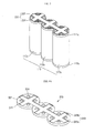
- FIG. 2 illustrates a perspective view of a first collector plate coupled to a plurality of prismatic electrode assemblies in a secondary battery according to another embodiment of the invention
- FIG. 3 illustrates a perspective view of a first collector plate coupled to a plurality of electrode assemblies in a secondary battery according to another embodiment of the invention
- FIG. 4A illustrates a perspective view of a first collector plate of a secondary battery according to another embodiment of the invention
- FIG. 4B illustrates a perspective view of an upturned bottom surface of the first collector plate of FIG. 4A ;
- FIG. 5 illustrates a perspective exploded view of the first collector plate of FIG. 4A on a plurality of electrode assemblies
- FIG. 6 illustrates a cross-sectional view of a secondary battery according to another embodiment of the invention.
- FIG. 7 illustrates a cross-sectional view of a secondary battery according to another embodiment of the invention.
- FIG. 1A illustrates a perspective view of a secondary battery according to an embodiment of the invention
- FIG. 1B illustrates a cross-sectional view of the secondary battery of FIG. 1A
- FIG. 1C illustrates a perspective view of a state in which an electrode assembly is stacked before it is wound in the secondary battery of FIG. 1B
- FIG. 1D illustrates a perspective view of a state in which a first collector plate is coupled to a plurality of electrode assemblies in the secondary battery of FIG. 1B
- FIG. 2 illustrates a perspective view of a state in which the first collector plate of FIG. 1D is coupled to a plurality of prismatic electrode assemblies.
- a secondary battery 100 includes a plurality of electrode assemblies 110, a first collector plate 120, a case 130, and a cap assembly 140.
- the plurality of electrode assemblies 110 includes small-capacity electrode assemblies.
- the electrode assemblies 110 include a first electrode assembly 110a, a second electrode assembly 110b, and a third electrode assembly 110c.
- the plurality of electrode assemblies 110 includes three electrode assemblies 110a, 110b, and 110c, the invention is not limited thereto.
- the plurality of electrode assemblies 110 may include more electrode assemblies.
- a “small capacity” may be defined as a capacity of a secondary battery that is applicable to portable small-sized electric devices, e.g., a portable terminal or a camcorder.
- a “large capacity” may be defined as a capacity of a secondary battery that is applicable to a power source for driving a motor in an electric tool or hybrid vehicle.
- the first electrode assembly 110a With respect to the plurality of electrode assemblies 110, the first electrode assembly 110a will be described in detail as an example.
- a first electrode plate 111, a separator 113, and a second electrode plate 112, which have thin plate or film shapes, are stacked and wound to form the first electrode assembly 110a.
- the first electrode plate 111 and the second electrode plate 112 have respective polarities that are different from each other.
- the first electrode plate 111 may be a negative electrode
- the second electrode plate 112 may be a positive electrode.
- the first electrode plate 111 includes a first electrode collector 111a and a first electrode coating portion 111b coated on both surfaces of the first electrode collector 111a. Furthermore, a first electrode non-coating portion 111c, on which a first electrode active material is not coated, is disposed on the first electrode collector 111a.
- the first electrode collector 111a has a foil shape for collecting current, and may be formed of, e.g., nickel (Ni) or copper (Cu).
- the first electrode coating portion 111b serves to generate electricity, and may be formed of, e.g., graphite or carbon.
- the first electrode non-coating portion 111c is disposed at a side, e.g., a terminal edge, of the first electrode collector 111a to provide a current flow path between the first electrode plate 111 and the outside.
- the second electrode plate 112 includes a second electrode collector 112a and a second electrode coating portion 112b coated on both surfaces of the second electrode collector 112a. Furthermore, a second electrode non-coating portion 112c, on which a second electrode active material is not coated, is disposed on the second electrode collector 112a.
- the second electrode collector 112a has a foil shape for collecting current, and may be formed of, e.g., aluminum (Al).
- the second electrode coating portion 112b serves to generate electricity, and may be formed of a transition metal oxide, e.g., LiCoO 2 LiNiO 2 , LiMn 2 O 4 , etc.
- the second electrode non-coating portion 112c is disposed at a side, e.g., a terminal edge, of the second electrode collector 112a to provide a current flow path between the second electrode plate 112 and the outside.
- the separator 113 is disposed between the first electrode plate 111 and the second electrode plate 112 to prevent the first electrode plate 111 and the second electrode plate 112 from being short-circuited.
- the separator 113 may allow only lithium ions to be moved.
- the separator 113 may include, e.g., a polyethylene film, a polypropylene film, a composite film of polyethylene and polypropylene, etc.
- the first electrode plate 111, the separator 113, and the second electrode plate 112 are disposed and wound, such that the first electrode non-coating portion 111c and the second electrode non-coating portion 112c protrude to the outside from opposite sides of the first electrode assembly 110a.
- the first electrode non-coating portion 111c protrudes toward a top of the first electrode assembly 110a
- the second electrode non-coating portion 112c protrudes toward a bottom, i.e., an opposite side with respect to the top, of the first electrode assembly 110a.
- the first electrode plate 111, the separator 113, and the second electrode plate 112 are spirally wound, e.g., to have a cross-section of a vortex as viewed from a plan view, or stacked to form the first electrode assembly 110a.
- the resulting structure is generally cylindrical and may have a generally circular cross-section (as shown in FIG. 1 ) or some other shape of cross-section (e.g. prismatic, as shown in FIG. 2 ).
- the first electrode assembly 110a may be cylindrically wound, e.g., the electrode plates 111/112 and separator 113 may be wound to define a plurality of concentric cylinders with gradually increasing diameters.
- the second electrode assembly 110b and the third electrode assembly 110c have the same configuration and manufacturing method as the first electrode assembly 110a and, therefore, their descriptions will not be repeated.
- the first electrode assembly 110a, the second electrode assembly 110b, and the third electrode assembly 110c are disposed in a line and are parallel to each other. They are also adjacent to each other, and fixed as one body by a fixing tape (not shown). More specifically, the first through third electrode assemblies 110a through 110c are aligned so that top surfaces, (i.e., surfaces substantially parallel to a bottom 131 of the case 130 and including terminal edges of the first electrode non-coating portions 111c), of the first through third electrodes assemblies 100a through 110c are substantially coplanar. In addition, the top surfaces of the first through third electrode assemblies 110a through 110c are aligned to have diameters of planar cross-sections of the top surfaces aligned.
- the plurality of electrode assemblies 110 have a first side thereof, i.e., the top surface, coupled to the first collector plate 120.
- the first electrode non-coating portions 111c of the first electrode plates 111 of the plurality of electrode assemblies 110 are electrically connected to each other via the first collector plate 120.
- the other sides of the electrode assemblies 110 i.e., second sides opposite the first sides, make contact with the case 130 to have an opposite polarity with respect to the first collector plate 120 and to electrically connect the second electrode plates 112 of the electrode assemblies 110.
- the first collector plate 120 is formed of a conductive material, and contacts the first electrode non-coating portions 111c protruding from the plurality of electrode assemblies 110.
- it is a linear member positioned to overlap the top surfaces of the first through third electrode assemblies 110a through 110c, such that it is aligned with diameters of the top surfaces. Therefore, the first collector plate 120 electrically connects the first electrode non-coating portions 111c of the plurality of electrode assemblies 110 to each other in a parallel connection.
- the first collector plate 120 is electrically connected to the first electrode plate 111 and to a first electrode terminal 142, thereby providing a current flow path between the plurality of electrode assemblies 110 and an external electric device.
- the first collector plate 120 includes a long strip shaped plate to integrally connect the first electrode non coating portions 111c of the plurality of electrode assemblies 110.
- the first collector plate 120 is directly welded to the first electrode non-coating portion 111c of the plurality of electrode assemblies 110 using a welding process.
- the plurality of electrode assemblies 110 have cylindrical shapes in FIG. 1D , but the invention is not limited thereto.
- the plurality of electrode assemblies 210 may have prismatic shapes.
- the case 130 includes a bottom portion 131 for receiving an electrolyte (not shown), the plurality of electrode assemblies 110, the first collector plate 120, and a sidewall 132 extending from the bottom portion 131.
- the case 130 has an open upper portion through which the plurality of electrode assemblies 110 and the first collector plate 120 are inserted into the case 130.
- the case 130 may be formed of a conductive material, e.g., aluminum, an aluminum alloy, steel coated with nickel, etc., and may serve as an electrode having one polarity.
- the second electrode non-coating portions 112c of the plurality of electrode assemblies 110 contact the bottom portion 131 of the case 130 and may be welded by a welding process.
- the case 130 may be electrically connected to the second electrode non-coating portions 112c to serve as a second collector plate.
- an inner surface of the sidewall 132 is treated to insulate the sidewall 132 from the first electrode non-coating portions 111c and the first collector plate 120 having a polarity different from the case 130.
- the cap assembly 140 includes a cap plate 141, the first electrode terminal 142, a first gasket 143, and a first nut 144.
- the cap plate 141 seals the case 130.
- the first electrode terminal 142 passes through the cap plate 141 and is connected to the first collector plate 120.
- the first gasket 143 is disposed between the first electrode terminal 142 and the cap plate 141 to insulate the first electrode terminal 142 from the cap plate 141.
- the first nut 144 is coupled along a screw thread S disposed on the first electrode terminal 142 to fix the first electrode terminal 142 to the cap plate 141.
- the first electrode terminal 142 is exposed to the outside of the cap assembly 140 and is disposed in a central region of the cap plate 141. Also, an inner surface of the cap plate 141 is insulated to prevent it from being unnecessarily electrically short-circuited.
- the cap assembly 140 includes a plug 145 sealing an electrolyte injecting hole (not shown) after electrolyte is injected through the electrolyte injecting hole formed in the cap plate 141.
- the cap assembly 140 further includes a safety vent 146 having a thin thickness and configured to break at a set pressure to exhaust gas.
- the plurality of electrode assemblies 110 are inserted into the case 130 through the open upper portion of the case 130.
- the electrolyte is injected into the case 130, and the cap assembly 140 serves to cover and seal the open upper portion of the case 130 to complete the secondary battery.
- the secondary battery 100 includes the plurality of small-capacity electrode assemblies 110 and the first collector plate 120 electrically connecting the electrode assemblies 110 to each other. Therefore, manufacturing equipment for an existing small-capacity secondary battery may be maintained as it is to realize the large-capacity secondary battery.
- changes of equipment and process for manufacturing small-capacity secondary batteries into equipment and process for manufacturing large-capacity secondary batteries e.g., a battery including a single electrode assembly having a large capacity, are not necessary.
- a secondary battery 100 according to this embodiment it is possible to improve and reduce the completed process and costs due to the elimination of a need to change the manufacturing equipment and process.
- the secondary battery 100 when an external force is applied to the plurality of small-capacity electrode assemblies, only one electrode assembly may be damaged.
- the amount of generated heat can be relatively low, as compared to heat generated when an external force is applied to one large-capacity electrode assembly. Therefore, in the secondary battery 100 according to this embodiment, the possibility of an explosion is reduced, and safety is improved.
- FIG. 3 illustrates a perspective view of a state in which a first collector plate is coupled to a plurality of electrode assemblies in a secondary battery.
- the secondary battery according to this embodiment has the same configuration and operation as the secondary battery 100 discussed previously with reference to FIGS. 1A-1D , with the exception of the first collector plate 220. Thus, duplicate descriptions will not be repeated.
- the first collector plate 220 includes a first plate 221 and a number of second plates 222.
- the first and second plates 221 and 222 are formed integrally with each other.
- the first plate 221 contacts first electrode non-coating portions 111c of a plurality of electrode assemblies 110 to integrally connect the first electrode non-coating portions 111c of the plurality of electrode assemblies 110 to each other.
- the first plate 221 has a substantially the same shape as that of the first collector plate 120 described previously with reference to FIG. 1A-1D .
- each second plate 222 is cross-connected to the first plate 221, and contacts the respective first electrode non-coating portions 111c. More specifically a second plate 222 is formed on the top surface of each respective electrode assembly 110 to cross the first plate 221.
- the secondary battery includes one first plate 221 continuously extending along a first direction on, e.g., directly on, the top surfaces of the first through third electrode assemblies 110a through 110c.
- the secondary battery includes three discrete second plates 222, each extending along a second direction i.e., a direction substantially perpendicular to the first direction and located on a respective top surface of one of the first through third electrode assemblies 110a through 110c.
- the first plate 221 and a second plate 222 cross each other to form a cross shape on each of the respective first electrode non-coating portions 111c of the first electrode assembly 110a, the second electrode assembly 110b, and the third electrode assembly 110c.
- the contact area between the first collector plate 220 and the first electrode non-coating portions 111c is increased in order to widen a current flow path between the plurality of electrode assemblies 110 and an external electric device.
- FIG. 4A is a perspective view of a first collector plate of the secondary battery according to this embodiment
- FIG. 4B is a perspective view of an upturned bottom surface of the first collector plate of FIG. 4A
- FIG. 5 is a perspective view of a state before the first collector plate of FIG. 4A is coupled to a plurality of electrode assemblies. It is noted that the configuration and operation of the secondary battery in FIGS. 4A , 4B , and 5 is substantially the same as that of the secondary battery 100 discussed previously with reference to FIGS. 1A-1D , with the exception of the first collector plate 320 and the plurality of electrode assemblies 310 including a receiving portion 315. Thus, duplicate descriptions will not be repeated.
- the first collector plate 320 completely surrounds, first electrode non-coating portions 311c of the plurality of electrode assemblies 310. Consequently, the first collector plate 320 provides a wide current flow path between the plurality of electrode assemblies 310 and the first electrode terminal 142 ( FIG. 1B ).
- the first collector plate 320 includes a first base 321, a first sidewall 322, a first welding portion 323, and electrolyte through holes 324.
- the first base 321 includes connected plates having cross-sections corresponding to cross-sections of top surfaces of the electrodes assemblies, e.g., circular plates as illustrated in FIG. 4A . As illustrated in FIG. 5 , the connected circular plates of the first base 321 face the first electrode non-coating portions 311c of the first electrode assembly 310a, the second electrode assembly 310b, and the third electrode assembly 310c.
- the first sidewall 322 extends from a point on a perimeter of the first base 321, toward the plurality of electrode assemblies 310 in a plane perpendicular to a plane of the first base 321, as illustrated in FIG. 4B .
- the first sidewall 322 completely surrounds the first base 321 and surrounds lateral portions of the first electrode non-coating portions 311c of the plurality of electrode assemblies 310 when coupled to the electrode assemblies 110.
- the first welding portion 323 is disposed in the first base 321, and protrudes toward the plurality of electrode assemblies 310. In other words, as illustrated in FIG. 4B , the first welding portion 323 and the first sidewall 322 protrude from the first base 321 in the same direction.
- the first welding portion 323 surface-contacts the first electrode non-coating portions 311c.
- the first welding portion 323 provides a welding space in which the first collector plate 320 is welded to the first electrode non-coating portions 311 of the plurality of electrode assemblies 310 using a welding process.
- the first collector plate 320 may be injection-molded, or the first base 321 may be separately pressed to form the first welding portion 323.
- the first welding portion 323 includes a first protrusion 323a and a number of second protrusions 323b.
- the first protrusion 323a has a shape substantially the same as that of the first plate 120 described previously with reference to FIGS. 1A-1D , and contacts the first electrode non-coating portions 311c of the plurality of electrode assemblies 310 to integrally connect the first electrode non-coating portions 311c to each other.
- the first protrusion 323a has a long rectangular shape in plan view.
- the second protrusions 323b are each cross-connected to the first protrusion 323a and they each contact a respective first electrode non-coating portion 311c.
- the relative configuration of the first and second protrusions 323a and 323b corresponds to that of the first and second plates 221 and 222 described previously with reference to FIG. 3 .
- the first electrolyte through holes 324 are formed through the first base 321.
- Each first electrolyte through hole 324 is defined around the first welding portion 323 of the first base 321, e.g., at a respective corner defined by the first and second protrusions 323a and 323b, to provide a path through which electrolyte is injected into the plurality of electrode assemblies 310 when the electrolyte is injected into the case 130.
- the first welding portion 323 is received, i.e., fits, into the receiving portion 315 in the first electrode non-coating portions 311c of the plurality of electrode assemblies 310 to couple the first collector plate 320 to the plurality of electrode assemblies 310.
- the shape of the first and second protrusions 323a and 323b correspond to the shape of the first collector plate 220 described previously with reference to FIG. 3 .
- a portion of the first electrode non-coating portions 311c disposed inside a portion cut by a cutting device (not shown) may be pressed by a pressing device (not shown) to form the receiving portion 315 in a groove shape in an upper portion of the respective first electrode non-coating portions 311c.
- a single receiving portion 315 is formed to overlap all the top surfaces of the non-coating portions 311c.
- the cut portion of the respective first electrode non-coating portions 311c corresponds to an outer perimeter line of the first welding portion 323 as viewed in plan view.
- the receiving portion 315 receives the first welding portion 323 having a shape protruding toward the plurality of electrode assemblies 310.
- the first welding portion 323 extends to a predetermined depth into the electrode assemblies 310 to completely fill the receiving portion 315, when the first collector plate 320 is coupled to the plurality of electrode assemblies 310.
- the receiving portion 315 allows the first collector plate 320 to be smoothly coupled to the plurality of electrode assemblies 310.
- a surface contact area between the first welding portion 323 and the first electrode non-coating portions 311c may increase to easily weld the first welding portion 323 to the first electrode non-coating portions 311c.
- the secondary battery in FIG. 5 includes the first collector plate 320 configured to completely surround the first electrode non-coating portions 311 of the plurality of electrode assemblies 310, the current flow path between the plurality of electrode assemblies 310 and an external electric device may be improved. Thus, a current flow between the plurality of electrode assemblies 310 and the external electric device may increase.
- the secondary battery includes the plurality of electrode assemblies 310 with the receiving portion 315, the first welding portion 323 protruding toward the plurality of electrode assemblies 310 may be smoothly inserted into the receiving portion 315 of the respective electrode assemblies 310.
- the plurality of electrode assemblies 310 may be easily coupled to the first collector plate 320.
- FIG. 6 illustrates a cross-sectional view of the secondary battery according to this embodiment.
- the secondary battery 400 has the same configuration and operation as the secondary battery 100 described previously with reference to FIGS. 1A-1D , with the exception of further including a second collector plate 450. Thus, duplicate descriptions will not be repeated.
- the secondary battery 400 includes the plurality of electrode assemblies 110, the first collector plate 120, the case 130, the cap assembly 140, and the second collector plate 450. Also, the secondary battery 400 includes a second electrode terminal 462, a second gasket 463, and a second nut 464.
- the second collector plate 450 is formed of a conductive material, and may contacts the second electrode non-coating portions 112c protruding from the other end of the plurality of electrode assemblies 110. Therefore, the second collector plate 450 electrically connects, the second electrode non-coating portions 112c of the plurality of electrode assemblies 110 to each other in parallel.
- the second collector plate 450 is electrically connected to the second electrode plate 112 and the second electrode terminal 462 to provide a current flow path between the plurality of electrode assemblies 110 and an external electric device.
- the second collector plate 450 may have the same configuration as the first collector plate 120 of FIG. 1D , the first collector plate 220 of FIG. 3 , or the first collector plate 320 of FIG. 4A . Also, the second collector plate 450 may be directly welded to the second electrode non-coating portions 112c of the plurality of electrode assemblies 110.
- the second electrode terminal 462 passes through the bottom portion 131 of the case 130 and is connected to the second collector plate 450.
- the second electrode terminal 462 may be welded to the second collector plate 450 using a welding process.
- the second electrode terminal 462 is disposed in a central region of the bottom portion 131.
- the first and second electrode terminals 142 and 462 is collinearly disposed, e.g., overlap a same electrode assembly 110, in a direction substantially perpendicular to an arrangement direction, i.e., a direction substantially parallel to a line connecting the plurality of electrode assemblies 110, of the plurality of the electrode assemblies 110. In this case, position determination may be easy when the secondary battery is coupled to the external electric device.
- the second gasket 463 is disposed between the second electrode terminal 462 and the bottom portion 131 to insulate the second electrode terminal 462 from the bottom portion 131. Consequently, an inner surface of the case 130 is insulated to prevent it from being unnecessarily electrically short-circuited.
- the second nut 464 is coupled along the screw thread S disposed on the second electrode terminal 462 to fix the second electrode terminal 462 to the bottom portion 131.
- the secondary battery 400 includes the second collector plate 450, a current flow between the first collector plate 120, as well as the plurality of electrode assemblies 110, and an external electric device may increase.
- FIG. 7 illustrates a cross-sectional view of the secondary battery.
- the secondary battery 500 has the same configuration and operation as the secondary battery 400 of FIG. 6 , except for positions of first electrode terminal 542 and second electrode terminal 562. Thus, duplicate descriptions will not be repeated.
- the secondary battery 500 includes the plurality of electrode assemblies 110, the first collector plate 120, the case 130, a cap assembly 540, and the second collector plate 450. Also, the secondary battery 500 includes a second electrode terminal 562, a second gasket 563, and a second nut 564.
- the cap assembly 540 includes the cap plate 141, a first electrode terminal 542, a first gasket 543, a first nut 544, a plug 145, and a safety vent 546.
- the cap assembly 540 is similar to the cap assembly 440 of FIG. 6 .
- positions of the first electrode terminal 542, the first gasket 543, the first nut 544, and a safety vent 546 are different from those of the first electrode terminal 142, the first gasket 143, the first nut 144, and the safety vent 146 of the cap assembly 140 of FIG. 6 .
- the first electrode terminal 542 is disposed on one side of the first collector plate 120. In particular, the first electrode terminal 542 is disposed over a first electrode assembly 110a.
- first gasket 543 and the first nut 544 are coupled to the first electrode terminal 542, positions of the first gasket 543 and the first nut 544 may be changed according to a position of the first electrode terminal 542. Since the first electrode terminal 542 is disposed on the one side of the first collector plate 120, the safety vent 546 may be disposed in a central region of the first collector plate 120.
- the second electrode terminal 562 is disposed on one side of the second collector plate 450. In particular, the second electrode terminal 562 is disposed below a third electrode assembly 110c.
- the second electrode terminal 562 and the first electrode terminal 542 are symmetrically disposed about a center of the plurality of electrode assemblies 110, i.e., a center of a second electrode assembly 110b in an arrangement direction of the plurality of electrode assemblies 110.
- the second electrode terminal 562 and the first electrode terminal 542 are disposed on opposite sides of the case 130, e.g., to overlap different electrodes assemblies 110, such that a line connecting the first and second electrode terminals 542 and 562 has a diagonal orientation with respect to the case 130.
- a charge/discharge path through the first electrode assembly 110a, a charge/discharge path through the second electrode assembly 110b, and a charge/discharge path through the third electrode assembly 110c may have the same length as each other between the first electrode terminal 542 and the second electrode terminal 562.
- the amount of heat generated during charge and discharge through each of the first electrode assembly 110a, the second electrode assembly 110b, and the third electrode assembly 110c may be minimized, in order to reduce degradation of each of the first electrode assembly 110a, the second electrode assembly 110b, and the third electrode assembly 110c. Therefore, the life cycle of the secondary battery 500 may be increased.
- prismatic electrode assemblies 210 Although a plurality of prismatic electrode assemblies 210 is described with reference to FIG. 2 , the prismatic electrode assemblies may be implemented in other embodiments. For example, the prismatic electrode assemblies are equally applicable to the embodiments described with reference to FIGS. 3 to 7 .
- a secondary battery with large capacity may include a plurality of small-capacity electrode assemblies and a collector plate electrically connecting the electrode assemblies to each other, so manufacturing equipment for the existing small-capacity secondary battery may be maintained without changes to realize the large-capacity secondary battery.
- manufacturing equipment for the existing small-capacity secondary battery may be maintained without changes to realize the large-capacity secondary battery.
- it may be possible to improve and reduce the completed process and costs.
- a secondary battery according to the invention when external force is applied to the plurality of small-capacity electrode assemblies, only one electrode assembly of the plurality of electrode assemblies may be damaged. Thus, the amount of generated heat may decrease, as compared to that when external force is applied to one large-capacity electrode assembly. Therefore, in a secondary battery according to the invention, the potential for explosion may be reduced, and safety may be improved.
Landscapes
- Chemical & Material Sciences (AREA)
- Chemical Kinetics & Catalysis (AREA)
- Electrochemistry (AREA)
- General Chemical & Material Sciences (AREA)
- Engineering & Computer Science (AREA)
- Manufacturing & Machinery (AREA)
- Inorganic Chemistry (AREA)
- Connection Of Batteries Or Terminals (AREA)
- Secondary Cells (AREA)
- Sealing Battery Cases Or Jackets (AREA)
Abstract
Description
- The invention relates to a rechargeable secondary battery.
- Secondary batteries are rechargeable batteries that can be charged and discharged. Generally, such a secondary battery is realized as a small-capacity secondary battery including one electrode assembly. A small-capacity secondary battery is typically employed in a portable small-sized electric devices, such as a portable terminal or a camcorder.
- In recent years, secondary batteries have been also realized as large capacity secondary batteries to be employed as power sources for driving motors in electric tools and hybrid vehicles, for example. However, conventional large-capacity secondary batteries are such that the manufacturing equipment and processes used for realizing the existing small-capacity secondary batteries need substantial modification before they can be used in manufacturing such a large-capacity secondary battery. Such changes in manufacturing equipment and processes tend to be complicated and costly.
- The present invention is therefore directed to a rechargeable battery which substantially overcomes one or more of the problems due to the limitations and disadvantages of the related art.
- It is therefore an object of the invention to provide a rechargeable secondary battery structure that realizes a large-capacity secondary battery using manufacturing equipment for a small-capacity second battery.
- It is another object of the invention to provide a rechargeable secondary battery structure with improved safety.
- Accordingly, the invention provides a secondary battery, including a first electrode plate having a first electrode non-coating portion, a second electrode plate having a second electrode non-coating portion, and a separator disposed between the first electrode plate and the second electrode plate, the plurality of electrode assemblies being disposed in one direction, a first collector plate contacting the first electrode non-coating portions of the plurality of electrode assemblies, the first collector plate electrically connecting the first electrode non-coating portions to each other in a parallel connection, and a case receiving the plurality of electrode assemblies and the first collector plate.
- The first electrode non-coating portions may protrude to one side of the plurality of electrode assemblies, and the second electrode non-coating portions may protrude to the other side of the plurality of electrode assemblies.
- The electrode assemblies may be disposed adjacent to each other.
- The first collector plate may include a plate integrally connecting the first electrode non-coating portions to each other.
- The first collector plate may have a strip shape.
- The first collector plate may include a first plate integrally connecting the first electrode non-coating portions to each other, and a second plate cross-connected to the first plate, the second plate contacting the respective first electrode non-coating portions.
- The first plate and the second plate may be cross-connected to each other to form a cross shape.
- The first collector plate may include a first welding portion protruding toward the plurality of electrode assemblies, the first welding portion being welded to the first electrode non-coating portions.
- The first collector plate may include a first base having a plate facing the first electrode non-coating portions of the plurality of electrode assemblies, and a first sidewall extending from an end of the first base toward the plurality of electrode assemblies to surround the first electrode non-coating portions of the plurality of electrode assemblies, wherein the first welding portion is disposed in the first base.
- The first welding portion may include a first protrusion contacting the first electrode non-coating portions of the plurality of electrode assemblies to integrally connect the first electrode non-coating portions of the plurality of electrode assemblies to each other, and a second protrusion cross-connected to the first protrusion, the second protrusion contacting the respective first electrode non-coating portions.
- The plurality of electrode assemblies may include a receiving portion disposed in a groove shape in a region corresponding to the first welding portion of the first electrode non-coating portions.
- The secondary battery may further include a cap assembly sealing the case.
- The cap assembly may include a first electrode terminal exposed to the outside of the cap assembly in a region facing the first collector plate, the first electrode terminal being welded to the first collector plate.
- The second electrode non-coating portions of the plurality of electrode assemblies may be welded to the case.
- The first electrode plate, the separator, and the second electrode plate may be wound to form the electrode assembly.
- The electrode assembly may have a cylindrical or prismatic shape.
- The secondary battery may further include a second collector plate contacting the second electrode non-coating portions of the plurality of electrode assemblies, the second collector plate electrically parallelly connecting the second electrode non-coating portions to each other.
- The secondary battery may further include a second electrode terminal passing through the case facing the second collector plate, the second electrode terminal being welded to the second collector plate.
- The first electrode terminal may be disposed in a central region of the first collector plate, and the second electrode terminal may be disposed in a central region of the second collector plate, wherein the first electrode terminal and the second electrode terminal may be collinearly disposed in a direction perpendicular to an arrangement direction of the plurality of electrode assemblies.
- The first electrode terminal may be disposed at a side of the first collector plate, and the second electrode terminal may be disposed at a side of the second collector plate, wherein the first electrode terminal and the second electrode terminal may be symmetrically disposed about a center of the plurality of electrode assemblies in the arrangement direction of the plurality of electrode assemblies.
- At least one of the above and other features and advantages may be realized by providing a secondary battery, including a plurality of electrode assemblies including first electrode non-coating portions protruding toward one side and second electrode non-coating portions protruding toward the other side, the plurality of electrode assemblies being disposed in one direction, a first collector plate contacting the first electrode non-coating portions of the plurality of electrode assemblies, the first collector plate electrically connecting the first electrode non-coating portions to each other in a parallel connection, and a case receiving the first collector plate and the plurality of electrode assemblies, wherein the first collector plate is directly welded to the first electrode non-coating portions.
- The above and other features of the invention are set out in the claims.
- The above and other features and advantages will become more apparent to those of ordinary skill in the art upon making reference to the following description embodiments of the invention, which is given with reference to the attached drawings, in which:
-
FIG. 1A illustrates a perspective view of a secondary battery according to an embodiment of the invention; -
FIG. 1B illustrates a cross-sectional view of the secondary battery ofFIG. 1A ; -
FIG. 1C illustrates a perspective exploded view of an electrode assembly before being wound in the secondary battery ofFIG. 1B ; -
FIG. 1D illustrates a perspective view of a first collector plate coupled to a plurality of electrode assemblies in the secondary battery ofFIG. 1B ; -
FIG. 2 illustrates a perspective view of a first collector plate coupled to a plurality of prismatic electrode assemblies in a secondary battery according to another embodiment of the invention; -
FIG. 3 illustrates a perspective view of a first collector plate coupled to a plurality of electrode assemblies in a secondary battery according to another embodiment of the invention; -
FIG. 4A illustrates a perspective view of a first collector plate of a secondary battery according to another embodiment of the invention; -
FIG. 4B illustrates a perspective view of an upturned bottom surface of the first collector plate ofFIG. 4A ; -
FIG. 5 illustrates a perspective exploded view of the first collector plate ofFIG. 4A on a plurality of electrode assemblies; -
FIG. 6 illustrates a cross-sectional view of a secondary battery according to another embodiment of the invention; and -
FIG. 7 illustrates a cross-sectional view of a secondary battery according to another embodiment of the invention. - Embodiments of the invention will now be described more fully hereinafter with reference to the accompanying drawings; however, they may be embodied in different forms and should not be construed as limited to the embodiments set forth herein. Rather, these embodiments are provided so that this disclosure will be thorough and complete, and will fully convey the scope of the invention to those skilled in the art.
- In the drawing figures, the dimensions of layers and regions may be exaggerated for clarity of illustration. It will also be understood that when a layer or element is referred to as being "on" another layer or substrate, it can be directly on the other layer or substrate, or intervening layers may also be present. In addition, it will also be understood that when a layer is referred to as being "between" two layers, it can be the only layer between the two layers, or one or more intervening layers may also be present. Like reference numerals refer to like elements throughout.
-
FIG. 1A illustrates a perspective view of a secondary battery according to an embodiment of the invention, andFIG. 1B illustrates a cross-sectional view of the secondary battery ofFIG. 1A .FIG. 1C illustrates a perspective view of a state in which an electrode assembly is stacked before it is wound in the secondary battery ofFIG. 1B , andFIG. 1D illustrates a perspective view of a state in which a first collector plate is coupled to a plurality of electrode assemblies in the secondary battery ofFIG. 1B .FIG. 2 illustrates a perspective view of a state in which the first collector plate ofFIG. 1D is coupled to a plurality of prismatic electrode assemblies. - Referring to
FIGS. 1A to 1D , asecondary battery 100 according to an embodiment of the invention includes a plurality ofelectrode assemblies 110, afirst collector plate 120, acase 130, and acap assembly 140. - The plurality of
electrode assemblies 110 includes small-capacity electrode assemblies. Theelectrode assemblies 110 include afirst electrode assembly 110a, asecond electrode assembly 110b, and athird electrode assembly 110c. Although, the plurality ofelectrode assemblies 110 includes threeelectrode assemblies electrode assemblies 110 may include more electrode assemblies. - A "small capacity" may be defined as a capacity of a secondary battery that is applicable to portable small-sized electric devices, e.g., a portable terminal or a camcorder. A "large capacity" may be defined as a capacity of a secondary battery that is applicable to a power source for driving a motor in an electric tool or hybrid vehicle.
- With respect to the plurality of
electrode assemblies 110, thefirst electrode assembly 110a will be described in detail as an example. Referring toFIG. 1C , afirst electrode plate 111, aseparator 113, and asecond electrode plate 112, which have thin plate or film shapes, are stacked and wound to form thefirst electrode assembly 110a. Thefirst electrode plate 111 and thesecond electrode plate 112 have respective polarities that are different from each other. For example, thefirst electrode plate 111 may be a negative electrode, and thesecond electrode plate 112 may be a positive electrode. - The
first electrode plate 111 includes afirst electrode collector 111a and a firstelectrode coating portion 111b coated on both surfaces of thefirst electrode collector 111a. Furthermore, a firstelectrode non-coating portion 111c, on which a first electrode active material is not coated, is disposed on thefirst electrode collector 111a. - The
first electrode collector 111a has a foil shape for collecting current, and may be formed of, e.g., nickel (Ni) or copper (Cu). The firstelectrode coating portion 111b serves to generate electricity, and may be formed of, e.g., graphite or carbon. The firstelectrode non-coating portion 111c is disposed at a side, e.g., a terminal edge, of thefirst electrode collector 111a to provide a current flow path between thefirst electrode plate 111 and the outside. - The
second electrode plate 112 includes asecond electrode collector 112a and a secondelectrode coating portion 112b coated on both surfaces of thesecond electrode collector 112a. Furthermore, a secondelectrode non-coating portion 112c, on which a second electrode active material is not coated, is disposed on thesecond electrode collector 112a. - The
second electrode collector 112a has a foil shape for collecting current, and may be formed of, e.g., aluminum (Al). The secondelectrode coating portion 112b serves to generate electricity, and may be formed of a transition metal oxide, e.g., LiCoO2 LiNiO2, LiMn2O4, etc. The secondelectrode non-coating portion 112c is disposed at a side, e.g., a terminal edge, of thesecond electrode collector 112a to provide a current flow path between thesecond electrode plate 112 and the outside. - The
separator 113 is disposed between thefirst electrode plate 111 and thesecond electrode plate 112 to prevent thefirst electrode plate 111 and thesecond electrode plate 112 from being short-circuited. Theseparator 113 may allow only lithium ions to be moved. Theseparator 113 may include, e.g., a polyethylene film, a polypropylene film, a composite film of polyethylene and polypropylene, etc. - In the
first electrode assembly 110a, thefirst electrode plate 111, theseparator 113, and thesecond electrode plate 112 are disposed and wound, such that the firstelectrode non-coating portion 111c and the secondelectrode non-coating portion 112c protrude to the outside from opposite sides of thefirst electrode assembly 110a. For example, as illustrated inFIG. 1B , the firstelectrode non-coating portion 111c protrudes toward a top of thefirst electrode assembly 110a, and the secondelectrode non-coating portion 112c protrudes toward a bottom, i.e., an opposite side with respect to the top, of thefirst electrode assembly 110a. - The
first electrode plate 111, theseparator 113, and thesecond electrode plate 112 are spirally wound, e.g., to have a cross-section of a vortex as viewed from a plan view, or stacked to form thefirst electrode assembly 110a. When the electrode assembly is spirally wound, the resulting structure is generally cylindrical and may have a generally circular cross-section (as shown inFIG. 1 ) or some other shape of cross-section (e.g. prismatic, as shown inFIG. 2 ). For example, thefirst electrode assembly 110a may be cylindrically wound, e.g., theelectrode plates 111/112 andseparator 113 may be wound to define a plurality of concentric cylinders with gradually increasing diameters. Thesecond electrode assembly 110b and thethird electrode assembly 110c have the same configuration and manufacturing method as thefirst electrode assembly 110a and, therefore, their descriptions will not be repeated. - Referring to
FIG. 1D , thefirst electrode assembly 110a, thesecond electrode assembly 110b, and thethird electrode assembly 110c are disposed in a line and are parallel to each other. They are also adjacent to each other, and fixed as one body by a fixing tape (not shown). More specifically, the first throughthird electrode assemblies 110a through 110c are aligned so that top surfaces, (i.e., surfaces substantially parallel to abottom 131 of thecase 130 and including terminal edges of the firstelectrode non-coating portions 111c), of the first through third electrodes assemblies 100a through 110c are substantially coplanar. In addition, the top surfaces of the first throughthird electrode assemblies 110a through 110c are aligned to have diameters of planar cross-sections of the top surfaces aligned. - As illustrated in
FIG. 1B , the plurality ofelectrode assemblies 110 have a first side thereof, i.e., the top surface, coupled to thefirst collector plate 120. In particular, the firstelectrode non-coating portions 111c of thefirst electrode plates 111 of the plurality ofelectrode assemblies 110 are electrically connected to each other via thefirst collector plate 120. As further illustrated inFIG. 1B , the other sides of theelectrode assemblies 110, i.e., second sides opposite the first sides, make contact with thecase 130 to have an opposite polarity with respect to thefirst collector plate 120 and to electrically connect thesecond electrode plates 112 of theelectrode assemblies 110. - Referring to
FIG. 1D , thefirst collector plate 120 is formed of a conductive material, and contacts the firstelectrode non-coating portions 111c protruding from the plurality ofelectrode assemblies 110. In this particular embodiment it is a linear member positioned to overlap the top surfaces of the first throughthird electrode assemblies 110a through 110c, such that it is aligned with diameters of the top surfaces. Therefore, thefirst collector plate 120 electrically connects the firstelectrode non-coating portions 111c of the plurality ofelectrode assemblies 110 to each other in a parallel connection. As illustrated inFIG. 1B , thefirst collector plate 120 is electrically connected to thefirst electrode plate 111 and to afirst electrode terminal 142, thereby providing a current flow path between the plurality ofelectrode assemblies 110 and an external electric device. - The
first collector plate 120 includes a long strip shaped plate to integrally connect the first electrodenon coating portions 111c of the plurality ofelectrode assemblies 110. In this embodiment, thefirst collector plate 120 is directly welded to the firstelectrode non-coating portion 111c of the plurality ofelectrode assemblies 110 using a welding process. - The plurality of
electrode assemblies 110 have cylindrical shapes inFIG. 1D , but the invention is not limited thereto. For example, as illustrated inFIG. 2 the plurality ofelectrode assemblies 210 may have prismatic shapes. - The
case 130 includes abottom portion 131 for receiving an electrolyte (not shown), the plurality ofelectrode assemblies 110, thefirst collector plate 120, and asidewall 132 extending from thebottom portion 131. Thecase 130 has an open upper portion through which the plurality ofelectrode assemblies 110 and thefirst collector plate 120 are inserted into thecase 130. Thecase 130 may be formed of a conductive material, e.g., aluminum, an aluminum alloy, steel coated with nickel, etc., and may serve as an electrode having one polarity. In this embodiment, the secondelectrode non-coating portions 112c of the plurality ofelectrode assemblies 110 contact thebottom portion 131 of thecase 130 and may be welded by a welding process. As a result, thecase 130 may be electrically connected to the secondelectrode non-coating portions 112c to serve as a second collector plate. Thus, an inner surface of thesidewall 132 is treated to insulate thesidewall 132 from the firstelectrode non-coating portions 111c and thefirst collector plate 120 having a polarity different from thecase 130. - The
cap assembly 140 includes acap plate 141, thefirst electrode terminal 142, afirst gasket 143, and afirst nut 144. Thecap plate 141 seals thecase 130. Thefirst electrode terminal 142 passes through thecap plate 141 and is connected to thefirst collector plate 120. Thefirst gasket 143 is disposed between thefirst electrode terminal 142 and thecap plate 141 to insulate thefirst electrode terminal 142 from thecap plate 141. Thefirst nut 144 is coupled along a screw thread S disposed on thefirst electrode terminal 142 to fix thefirst electrode terminal 142 to thecap plate 141. Thefirst electrode terminal 142 is exposed to the outside of thecap assembly 140 and is disposed in a central region of thecap plate 141. Also, an inner surface of thecap plate 141 is insulated to prevent it from being unnecessarily electrically short-circuited. - Also, the
cap assembly 140 includes aplug 145 sealing an electrolyte injecting hole (not shown) after electrolyte is injected through the electrolyte injecting hole formed in thecap plate 141. Thecap assembly 140 further includes asafety vent 146 having a thin thickness and configured to break at a set pressure to exhaust gas. - The plurality of
electrode assemblies 110 are inserted into thecase 130 through the open upper portion of thecase 130. The electrolyte is injected into thecase 130, and thecap assembly 140 serves to cover and seal the open upper portion of thecase 130 to complete the secondary battery. - As described above, the
secondary battery 100 according to this embodiment of the invention includes the plurality of small-capacity electrode assemblies 110 and thefirst collector plate 120 electrically connecting theelectrode assemblies 110 to each other. Therefore, manufacturing equipment for an existing small-capacity secondary battery may be maintained as it is to realize the large-capacity secondary battery. As a result, in thesecondary battery 100 according to this embodiment of the invention, changes of equipment and process for manufacturing small-capacity secondary batteries into equipment and process for manufacturing large-capacity secondary batteries, e.g., a battery including a single electrode assembly having a large capacity, are not necessary. Thus, in the case of asecondary battery 100 according to this embodiment, it is possible to improve and reduce the completed process and costs due to the elimination of a need to change the manufacturing equipment and process. - In addition, in the
secondary battery 100 according to this embodiment, when an external force is applied to the plurality of small-capacity electrode assemblies, only one electrode assembly may be damaged. Thus, the amount of generated heat can be relatively low, as compared to heat generated when an external force is applied to one large-capacity electrode assembly. Therefore, in thesecondary battery 100 according to this embodiment, the possibility of an explosion is reduced, and safety is improved. - A secondary battery according to another embodiment of the invention will be described below with reference to
FIG. 3. FIG. 3 illustrates a perspective view of a state in which a first collector plate is coupled to a plurality of electrode assemblies in a secondary battery. The secondary battery according to this embodiment has the same configuration and operation as thesecondary battery 100 discussed previously with reference toFIGS. 1A-1D , with the exception of thefirst collector plate 220. Thus, duplicate descriptions will not be repeated. - Referring to
FIG. 3 , thefirst collector plate 220 includes afirst plate 221 and a number ofsecond plates 222. The first andsecond plates - The
first plate 221 contacts first electrodenon-coating portions 111c of a plurality ofelectrode assemblies 110 to integrally connect the firstelectrode non-coating portions 111c of the plurality ofelectrode assemblies 110 to each other. In this regard, thefirst plate 221 has a substantially the same shape as that of thefirst collector plate 120 described previously with reference toFIG. 1A-1D . - As illustrated in
FIG. 3 , eachsecond plate 222 is cross-connected to thefirst plate 221, and contacts the respective firstelectrode non-coating portions 111c. More specifically asecond plate 222 is formed on the top surface of eachrespective electrode assembly 110 to cross thefirst plate 221. For example, as illustrated inFIG. 3 , the secondary battery includes onefirst plate 221 continuously extending along a first direction on, e.g., directly on, the top surfaces of the first throughthird electrode assemblies 110a through 110c. As further illustrated inFIG. 3 , the secondary battery includes three discretesecond plates 222, each extending along a second direction i.e., a direction substantially perpendicular to the first direction and located on a respective top surface of one of the first throughthird electrode assemblies 110a through 110c. - In other words, the
first plate 221 and asecond plate 222 cross each other to form a cross shape on each of the respective firstelectrode non-coating portions 111c of thefirst electrode assembly 110a, thesecond electrode assembly 110b, and thethird electrode assembly 110c. Thus, the contact area between thefirst collector plate 220 and the firstelectrode non-coating portions 111c is increased in order to widen a current flow path between the plurality ofelectrode assemblies 110 and an external electric device. - A secondary battery according to another embodiment of the invention will be described below with reference to
FIGS. 4A ,4B , and5 .FIG. 4A is a perspective view of a first collector plate of the secondary battery according to this embodiment,FIG. 4B is a perspective view of an upturned bottom surface of the first collector plate ofFIG. 4A .FIG. 5 is a perspective view of a state before the first collector plate ofFIG. 4A is coupled to a plurality of electrode assemblies. It is noted that the configuration and operation of the secondary battery inFIGS. 4A ,4B , and5 is substantially the same as that of thesecondary battery 100 discussed previously with reference toFIGS. 1A-1D , with the exception of thefirst collector plate 320 and the plurality ofelectrode assemblies 310 including a receivingportion 315. Thus, duplicate descriptions will not be repeated. - Referring to
FIGS. 4A to 5 , thefirst collector plate 320 completely surrounds, firstelectrode non-coating portions 311c of the plurality ofelectrode assemblies 310. Consequently, thefirst collector plate 320 provides a wide current flow path between the plurality ofelectrode assemblies 310 and the first electrode terminal 142 (FIG. 1B ). Thefirst collector plate 320 includes afirst base 321, afirst sidewall 322, afirst welding portion 323, and electrolyte throughholes 324. - The
first base 321 includes connected plates having cross-sections corresponding to cross-sections of top surfaces of the electrodes assemblies, e.g., circular plates as illustrated inFIG. 4A . As illustrated inFIG. 5 , the connected circular plates of thefirst base 321 face the firstelectrode non-coating portions 311c of thefirst electrode assembly 310a, thesecond electrode assembly 310b, and thethird electrode assembly 310c. - As illustrated in
FIG. 5 , thefirst sidewall 322 extends from a point on a perimeter of thefirst base 321, toward the plurality ofelectrode assemblies 310 in a plane perpendicular to a plane of thefirst base 321, as illustrated inFIG. 4B . Thefirst sidewall 322 completely surrounds thefirst base 321 and surrounds lateral portions of the firstelectrode non-coating portions 311c of the plurality ofelectrode assemblies 310 when coupled to theelectrode assemblies 110. - The
first welding portion 323 is disposed in thefirst base 321, and protrudes toward the plurality ofelectrode assemblies 310. In other words, as illustrated inFIG. 4B , thefirst welding portion 323 and thefirst sidewall 322 protrude from thefirst base 321 in the same direction. When thefirst collector plate 320 is coupled to the plurality ofelectrode assemblies 310, thefirst welding portion 323 surface-contacts the firstelectrode non-coating portions 311c. Thefirst welding portion 323 provides a welding space in which thefirst collector plate 320 is welded to the first electrode non-coating portions 311 of the plurality ofelectrode assemblies 310 using a welding process. Thefirst collector plate 320 may be injection-molded, or thefirst base 321 may be separately pressed to form thefirst welding portion 323. Specifically, thefirst welding portion 323 includes afirst protrusion 323a and a number ofsecond protrusions 323b. - The
first protrusion 323a has a shape substantially the same as that of thefirst plate 120 described previously with reference toFIGS. 1A-1D , and contacts the firstelectrode non-coating portions 311c of the plurality ofelectrode assemblies 310 to integrally connect the firstelectrode non-coating portions 311c to each other. Specifically, thefirst protrusion 323a has a long rectangular shape in plan view. - The
second protrusions 323b are each cross-connected to thefirst protrusion 323a and they each contact a respective firstelectrode non-coating portion 311c. In particular, the relative configuration of the first andsecond protrusions second plates FIG. 3 . - The first electrolyte through
holes 324 are formed through thefirst base 321. Each first electrolyte throughhole 324 is defined around thefirst welding portion 323 of thefirst base 321, e.g., at a respective corner defined by the first andsecond protrusions electrode assemblies 310 when the electrolyte is injected into thecase 130. - As illustrated in
FIG. 5 , thefirst welding portion 323 is received, i.e., fits, into the receivingportion 315 in the firstelectrode non-coating portions 311c of the plurality ofelectrode assemblies 310 to couple thefirst collector plate 320 to the plurality ofelectrode assemblies 310. The shape of the first andsecond protrusions first collector plate 220 described previously with reference toFIG. 3 . - In detail, a portion of the first
electrode non-coating portions 311c disposed inside a portion cut by a cutting device (not shown) may be pressed by a pressing device (not shown) to form the receivingportion 315 in a groove shape in an upper portion of the respective firstelectrode non-coating portions 311c. In this embodiment, asingle receiving portion 315 is formed to overlap all the top surfaces of thenon-coating portions 311c. The cut portion of the respective firstelectrode non-coating portions 311c corresponds to an outer perimeter line of thefirst welding portion 323 as viewed in plan view. The receivingportion 315 receives thefirst welding portion 323 having a shape protruding toward the plurality ofelectrode assemblies 310. Thefirst welding portion 323 extends to a predetermined depth into theelectrode assemblies 310 to completely fill the receivingportion 315, when thefirst collector plate 320 is coupled to the plurality ofelectrode assemblies 310. Thus, the receivingportion 315 allows thefirst collector plate 320 to be smoothly coupled to the plurality ofelectrode assemblies 310. Also, since the firstelectrode non-coating portions 311c disposed in the receivingportion 315 are pressed by the pressing device, a surface contact area between thefirst welding portion 323 and the firstelectrode non-coating portions 311c may increase to easily weld thefirst welding portion 323 to the firstelectrode non-coating portions 311c. - As described above, since the secondary battery in
FIG. 5 includes thefirst collector plate 320 configured to completely surround the first electrode non-coating portions 311 of the plurality ofelectrode assemblies 310, the current flow path between the plurality ofelectrode assemblies 310 and an external electric device may be improved. Thus, a current flow between the plurality ofelectrode assemblies 310 and the external electric device may increase. - Also, since the secondary battery includes the plurality of
electrode assemblies 310 with the receivingportion 315, thefirst welding portion 323 protruding toward the plurality ofelectrode assemblies 310 may be smoothly inserted into the receivingportion 315 of therespective electrode assemblies 310. Thus, the plurality ofelectrode assemblies 310 may be easily coupled to thefirst collector plate 320. - A
secondary battery 400 according to another embodiment will be described below with reference toFIG. 6. FIG. 6 illustrates a cross-sectional view of the secondary battery according to this embodiment. Thesecondary battery 400 has the same configuration and operation as thesecondary battery 100 described previously with reference toFIGS. 1A-1D , with the exception of further including asecond collector plate 450. Thus, duplicate descriptions will not be repeated. - Referring to
FIG. 6 , thesecondary battery 400 includes the plurality ofelectrode assemblies 110, thefirst collector plate 120, thecase 130, thecap assembly 140, and thesecond collector plate 450. Also, thesecondary battery 400 includes asecond electrode terminal 462, asecond gasket 463, and asecond nut 464. - The
second collector plate 450 is formed of a conductive material, and may contacts the secondelectrode non-coating portions 112c protruding from the other end of the plurality ofelectrode assemblies 110. Therefore, thesecond collector plate 450 electrically connects, the secondelectrode non-coating portions 112c of the plurality ofelectrode assemblies 110 to each other in parallel. Thesecond collector plate 450 is electrically connected to thesecond electrode plate 112 and thesecond electrode terminal 462 to provide a current flow path between the plurality ofelectrode assemblies 110 and an external electric device. - The
second collector plate 450 may have the same configuration as thefirst collector plate 120 ofFIG. 1D , thefirst collector plate 220 ofFIG. 3 , or thefirst collector plate 320 ofFIG. 4A . Also, thesecond collector plate 450 may be directly welded to the secondelectrode non-coating portions 112c of the plurality ofelectrode assemblies 110. - The
second electrode terminal 462 passes through thebottom portion 131 of thecase 130 and is connected to thesecond collector plate 450. For example, thesecond electrode terminal 462 may be welded to thesecond collector plate 450 using a welding process. Also, thesecond electrode terminal 462 is disposed in a central region of thebottom portion 131. The first andsecond electrode terminals same electrode assembly 110, in a direction substantially perpendicular to an arrangement direction, i.e., a direction substantially parallel to a line connecting the plurality ofelectrode assemblies 110, of the plurality of theelectrode assemblies 110. In this case, position determination may be easy when the secondary battery is coupled to the external electric device. - The
second gasket 463 is disposed between thesecond electrode terminal 462 and thebottom portion 131 to insulate thesecond electrode terminal 462 from thebottom portion 131. Consequently, an inner surface of thecase 130 is insulated to prevent it from being unnecessarily electrically short-circuited. Thesecond nut 464 is coupled along the screw thread S disposed on thesecond electrode terminal 462 to fix thesecond electrode terminal 462 to thebottom portion 131. - As described above, since the
secondary battery 400 includes thesecond collector plate 450, a current flow between thefirst collector plate 120, as well as the plurality ofelectrode assemblies 110, and an external electric device may increase. - A
secondary battery 500 according to another embodiment will be described below with reference toFIG. 7. FIG. 7 illustrates a cross-sectional view of the secondary battery. Thesecondary battery 500 has the same configuration and operation as thesecondary battery 400 ofFIG. 6 , except for positions offirst electrode terminal 542 andsecond electrode terminal 562. Thus, duplicate descriptions will not be repeated. - Referring to
FIG. 7 , thesecondary battery 500 includes the plurality ofelectrode assemblies 110, thefirst collector plate 120, thecase 130, acap assembly 540, and thesecond collector plate 450. Also, thesecondary battery 500 includes asecond electrode terminal 562, asecond gasket 563, and asecond nut 564. - The
cap assembly 540 includes thecap plate 141, afirst electrode terminal 542, afirst gasket 543, afirst nut 544, aplug 145, and asafety vent 546. Thecap assembly 540 is similar to the cap assembly 440 ofFIG. 6 . However, positions of thefirst electrode terminal 542, thefirst gasket 543, thefirst nut 544, and asafety vent 546 are different from those of thefirst electrode terminal 142, thefirst gasket 143, thefirst nut 144, and thesafety vent 146 of thecap assembly 140 ofFIG. 6 . - The
first electrode terminal 542 is disposed on one side of thefirst collector plate 120. In particular, thefirst electrode terminal 542 is disposed over afirst electrode assembly 110a. - Since the
first gasket 543 and thefirst nut 544 are coupled to thefirst electrode terminal 542, positions of thefirst gasket 543 and thefirst nut 544 may be changed according to a position of thefirst electrode terminal 542. Since thefirst electrode terminal 542 is disposed on the one side of thefirst collector plate 120, thesafety vent 546 may be disposed in a central region of thefirst collector plate 120. - The
second electrode terminal 562 is disposed on one side of thesecond collector plate 450. In particular, thesecond electrode terminal 562 is disposed below athird electrode assembly 110c. Thesecond electrode terminal 562 and thefirst electrode terminal 542 are symmetrically disposed about a center of the plurality ofelectrode assemblies 110, i.e., a center of asecond electrode assembly 110b in an arrangement direction of the plurality ofelectrode assemblies 110. In particular, thesecond electrode terminal 562 and thefirst electrode terminal 542 are disposed on opposite sides of thecase 130, e.g., to overlapdifferent electrodes assemblies 110, such that a line connecting the first andsecond electrode terminals case 130. Thus, when thesecondary battery 500 is connected to an external electric device, a charge/discharge path through thefirst electrode assembly 110a, a charge/discharge path through thesecond electrode assembly 110b, and a charge/discharge path through thethird electrode assembly 110c may have the same length as each other between thefirst electrode terminal 542 and thesecond electrode terminal 562. Thus, the amount of heat generated during charge and discharge through each of thefirst electrode assembly 110a, thesecond electrode assembly 110b, and thethird electrode assembly 110c may be minimized, in order to reduce degradation of each of thefirst electrode assembly 110a, thesecond electrode assembly 110b, and thethird electrode assembly 110c. Therefore, the life cycle of thesecondary battery 500 may be increased. - Although a plurality of
prismatic electrode assemblies 210 is described with reference toFIG. 2 , the prismatic electrode assemblies may be implemented in other embodiments. For example, the prismatic electrode assemblies are equally applicable to the embodiments described with reference toFIGS. 3 to 7 . - As described above, a secondary battery with large capacity according to the invention may include a plurality of small-capacity electrode assemblies and a collector plate electrically connecting the electrode assemblies to each other, so manufacturing equipment for the existing small-capacity secondary battery may be maintained without changes to realize the large-capacity secondary battery. Thus, in the secondary battery according to the embodiments, it may be possible to improve and reduce the completed process and costs.
- Also, in a secondary battery according to the invention, when external force is applied to the plurality of small-capacity electrode assemblies, only one electrode assembly of the plurality of electrode assemblies may be damaged. Thus, the amount of generated heat may decrease, as compared to that when external force is applied to one large-capacity electrode assembly. Therefore, in a secondary battery according to the invention, the potential for explosion may be reduced, and safety may be improved.
- Embodiments of the invention have been disclosed herein, and although specific terms are employed, they are used and are to be interpreted in a generic and descriptive sense only and not for purpose of limitation. Accordingly, it will be understood by those of ordinary skill in the art that various changes in form and details may be made without departing from the scope of the present invention as set forth in the following claims.
Claims (19)
- A secondary battery, comprising:a plurality of electrode assemblies, each said electrode assembly including a first electrode plate with a first electrode non-coating portion, a second electrode plate with a second electrode non-coating portion, and a separator between the first electrode plate and the second electrode plate;a first collector plate contacting the first electrode non-coating portions of the plurality of electrode assemblies, the first collector plate electrically connecting the first electrode non-coating portions to each other in a parallel electrical connection; anda case configured to contain the plurality of electrode assemblies and the first collector plate.
- A secondary battery as claimed in claim 1, wherein the first electrode non-coating portions protrude to a first side of the plurality of electrode assemblies, and the second electrode non-coating portions protrude to a second side opposite the first side of the plurality of electrode assemblies.
- A secondary battery as claimed in claim 1 or 2, wherein the electrode assemblies are disposed adjacent to each other.
- A secondary battery as claimed in any preceding claim, wherein the first collector plate includes a plate integrally connecting the first electrode non-coating portions to each other.
- A secondary battery as claimed in claim 4, wherein the first collector plate has a stripe shape that overlaps all the electrode assemblies.
- A secondary battery as claimed in any preceding claim, wherein the first collector plate includes:a first plate integrally connecting the first electrode non-coating portions to each other; anda second plate cross-connected to the first plate, the second plate contacting a respective first electrode non-coating portion.
- A secondary battery as claimed in claim 6, comprising a plurality of second plates, wherein the first plate and each second plate are cross-connected to a respective said other to form a cross shape on each first electrode non-coating portion.
- A secondary battery as claimed in any preceding claim, wherein the first collector plate includes a first welding portion protruding from a base portion toward the plurality of electrode assemblies.
- A secondary battery as claimed in claim 8, wherein the first collector plate includes:the base portion with a plate facing each of the first electrode non-coating portions of the plurality of electrode assemblies, the first welding portion overlapping the plate of each of the first electrode non-coating portions; anda first sidewall extending from an edge of the base portion toward the plurality of electrode assemblies to surround the first electrode non-coating portions of the plurality of electrode assemblies.
- A secondary battery as claimed in claim 9, wherein the first welding portion includes:a first protrusion contacting the first electrode non-coating portions of the plurality of electrode assemblies to integrally connect the first electrode non-coating portions of the plurality of electrode assemblies to each other; anda plurality of second protrusions cross-connected to the first protrusion, each second protrusion contacting a respective one of the respective first electrode non-coating portions.
- A secondary battery as claimed in claim 8, 9 or 10 wherein the plurality of electrode assemblies includes a receiving portion in the first electrode non-coating portions, the receiving portion having a groove shape corresponding to the shape of the first welding portion.
- A secondary battery as claimed in any preceding claim, further comprising a cap assembly facing the first collector plate and configured to seal the case, the cap assembly including a first electrode terminal exposed to the outside of the cap assembly and connected to the first electrode terminal plate.
- A secondary battery as claimed in claim 12, further comprising a second collector plate contacting the second electrode non-coating portions of the plurality of electrode assemblies, the second collector plate electrically connecting the second electrode non-coating portions to each other in a parallel electrical connection.
- A secondary battery as claimed in claim 13, further comprising a second electrode terminal passing through a bottom of the case facing the second collector plate, the second electrode terminal being welded to the second collector plate.
- A secondary battery as claimed in claim 14, wherein:the first electrode terminal is disposed in a central region of the first collector plate, and the second electrode terminal is disposed in a central region of the second collector plate, andthe first electrode terminal and the second electrode terminal are collinearly disposed in a direction perpendicular to an arrangement direction of the plurality of electrode assemblies.
- A secondary battery as claimed in claim 14, wherein:the first electrode terminal is disposed at a side region of the first collector plate, and the second electrode terminal is disposed at a side region of the second collector plate, andthe first electrode terminal and the second electrode terminal are symmetrically disposed about a center of the plurality of electrode assemblies in the arrangement direction of the plurality of electrode assemblies.
- A secondary battery as claimed in any preceding claim , wherein the second electrode non-coating portions of the plurality of electrode assemblies are welded to the case.
- A secondary battery as claimed in any preceding claim, wherein:the first electrode plate, the separator, and the second electrode plate are wound to define the electrode assembly, andthe electrode assembly has a cylindrical shape or a prismatic shape.
- A method of forming a secondary battery, comprising:forming a plurality of electrode assemblies, each said electrode assembly including a first electrode plate with a first electrode non-coating portion, a second electrode plate with a second electrode non-coating portion, and a separator between the first electrode plate and the second electrode plate ;forming a first collector plate directly welded to the first electrode non-coating portions of the plurality of electrode assemblies, the first collector plate electrically connecting the first electrode non-coating portions to each other in a parallel electrical connection; andforming a case configured to receive the first collector plate and the plurality of electrode assemblies.
Applications Claiming Priority (1)
| Application Number | Priority Date | Filing Date | Title |
|---|---|---|---|
| KR1020090093342A KR101165503B1 (en) | 2009-09-30 | 2009-09-30 | Rechargeable battery |
Publications (3)
| Publication Number | Publication Date |
|---|---|
| EP2337137A2 true EP2337137A2 (en) | 2011-06-22 |
| EP2337137A3 EP2337137A3 (en) | 2013-11-27 |
| EP2337137B1 EP2337137B1 (en) | 2014-11-19 |
Family
ID=43780738
Family Applications (1)
| Application Number | Title | Priority Date | Filing Date |
|---|---|---|---|
| EP10251710.9A Not-in-force EP2337137B1 (en) | 2009-09-30 | 2010-09-30 | Rechargeable battery |
Country Status (5)
| Country | Link |
|---|---|
| US (1) | US8450006B2 (en) |
| EP (1) | EP2337137B1 (en) |
| JP (1) | JP5190491B2 (en) |
| KR (1) | KR101165503B1 (en) |
| CN (1) | CN102035012B (en) |
Cited By (1)
| Publication number | Priority date | Publication date | Assignee | Title |
|---|---|---|---|---|
| FR3019686A1 (en) * | 2014-04-08 | 2015-10-09 | Commissariat Energie Atomique | LITHIUM ELECTROCHEMICAL ACCUMULATOR WITH TERMINAL IN DIRECT CONNECTION WITH THE ELECTROCHEMICAL BEAM, METHODS OF MAKING THE SAME. |
Families Citing this family (26)
| Publication number | Priority date | Publication date | Assignee | Title |
|---|---|---|---|---|
| CN102339970A (en) * | 2011-10-28 | 2012-02-01 | 徐敖奎 | Lithium battery |
| US20130196194A1 (en) * | 2012-01-31 | 2013-08-01 | Samsung Sdi Co., Ltd. | Secondary battery |
| KR101800030B1 (en) | 2012-02-07 | 2017-11-21 | 삼성에스디아이 주식회사 | Electrode assembly and secondary battery comprising the same |
| CN103715386B (en) * | 2012-09-28 | 2016-08-31 | 统达能源股份有限公司 | The connection structure of the battery pack |
| FR3011128B1 (en) * | 2013-09-25 | 2015-10-30 | Commissariat Energie Atomique | METHOD FOR PRODUCING AN ELECTROCHEMICAL BEAM OF A LITHIUM ACCUMULATOR |
| KR20150101136A (en) * | 2014-02-26 | 2015-09-03 | 삼성에스디아이 주식회사 | Secondary battery |
| KR102517901B1 (en) | 2015-10-02 | 2023-04-03 | 삼성에스디아이 주식회사 | Rechargeable battery |
| KR102571182B1 (en) * | 2016-03-22 | 2023-08-24 | 삼성에스디아이 주식회사 | Rechargeable battery |
| KR102771991B1 (en) * | 2017-02-22 | 2025-02-25 | 삼성에스디아이 주식회사 | Secondary battery having symmetrical multi-tap |
| CN106910862A (en) * | 2017-02-28 | 2017-06-30 | 长沙安靠电源有限公司 | Plug-in type battery connecting apparatus |
| KR20190098495A (en) * | 2018-02-14 | 2019-08-22 | 삼성에스디아이 주식회사 | Electrode assembly and secondary battery comprising the same |
| US20190296311A1 (en) * | 2018-03-23 | 2019-09-26 | Sf Motors, Inc. | Battery cell for electric vehicle battery pack |
| KR102717976B1 (en) * | 2019-06-04 | 2024-10-16 | 에스케이온 주식회사 | Long width secondary battery |
| KR102147278B1 (en) | 2019-07-05 | 2020-08-24 | 에스케이이노베이션 주식회사 | Polyimide based film and film for cover window and display device comprising the same |
| KR102819179B1 (en) * | 2019-09-30 | 2025-06-11 | 삼성에스디아이 주식회사 | Secondary battery |
| KR20210145489A (en) * | 2020-05-25 | 2021-12-02 | 삼성에스디아이 주식회사 | Secondary battery |
| KR102663271B1 (en) * | 2021-03-24 | 2024-05-03 | 삼성에스디아이 주식회사 | Secondary battery |
| CN117941160A (en) * | 2021-08-30 | 2024-04-26 | 松下控股株式会社 | Battery and bonding method |
| EP4366073A4 (en) * | 2021-10-29 | 2025-08-13 | Lg Energy Solution Ltd | CYLINDRICAL BATTERY CELL AND BATTERY PACK THEREOF AS WELL AS VEHICLE THEREOF AND CURRENT COLLECTION PLATE |
| KR102945143B1 (en) * | 2021-10-29 | 2026-03-27 | 주식회사 엘지에너지솔루션 | cylindrical battery cell, and battery pack including the same and vehicle including the same and Current Collector plate |
| CN116666727A (en) * | 2022-02-17 | 2023-08-29 | 宁德时代新能源科技股份有限公司 | Battery cell, battery, electrical equipment and manufacturing method |
| CN217788449U (en) * | 2022-04-29 | 2022-11-11 | 湖北亿纬动力有限公司 | Battery and battery module |
| CN114865241B (en) * | 2022-05-13 | 2024-01-26 | 星恒电源股份有限公司 | Battery cell set, battery module and assembling method |
| KR20250143583A (en) * | 2024-03-25 | 2025-10-02 | 삼성에스디아이 주식회사 | Rechargeable battery |
| KR20250143373A (en) * | 2024-03-25 | 2025-10-02 | 삼성에스디아이 주식회사 | Secondary battery |
| WO2026079348A1 (en) * | 2024-10-08 | 2026-04-16 | 株式会社Gsユアサ | Power storage element |
Family Cites Families (33)
| Publication number | Priority date | Publication date | Assignee | Title |
|---|---|---|---|---|
| FR1510827A (en) * | 1966-04-01 | 1968-01-26 | Accumulateurs Fixes | Improvements to electrolytic cells, accumulators and electric batteries |
| FR2528628A1 (en) * | 1982-06-14 | 1983-12-16 | Accumulateurs Fixes | Electric accumulator with reinforced terminal for handling during mfr. - uses rolled construction with electrode having shallow V=shape profile extending in direction of cell axis to permit machine handling |
| JP3412473B2 (en) * | 1997-09-25 | 2003-06-03 | 新神戸電機株式会社 | Non-aqueous electrolyte battery using thin electrodes |
| JP4224186B2 (en) | 1999-06-10 | 2009-02-12 | パナソニック株式会社 | Collective secondary battery |
| JP3334683B2 (en) * | 1999-06-28 | 2002-10-15 | エヌイーシートーキン株式会社 | Non-aqueous electrolyte secondary battery and method of manufacturing the same |
| JP2002324568A (en) * | 2001-04-24 | 2002-11-08 | Yuasa Corp | Battery with multiple wound electrode groups |
| JP4060590B2 (en) * | 2001-05-02 | 2008-03-12 | 日本碍子株式会社 | Method for manufacturing lithium secondary battery |
| JP2002346770A (en) * | 2001-05-24 | 2002-12-04 | Hitachi Ltd | Aluminum base joint structure |
| JP4293501B2 (en) * | 2001-08-24 | 2009-07-08 | Tdk株式会社 | Electrochemical devices |
| DE10146957A1 (en) * | 2001-09-24 | 2003-04-17 | Nbt Gmbh | Tightly sealed accumulator |
| US7129001B2 (en) * | 2001-12-18 | 2006-10-31 | Gs Yuasa Corporation | Cell comprising a power-generating element fastened by sheets |
| US7718312B2 (en) * | 2002-05-27 | 2010-05-18 | Gs Yuasa Corporation | Battery |
| JP4166063B2 (en) * | 2002-09-18 | 2008-10-15 | 松下電器産業株式会社 | Square battery |
| JP3811894B2 (en) | 2003-02-14 | 2006-08-23 | 株式会社日立製作所 | Secondary battery device for hybrid railway vehicles |
| KR100516768B1 (en) | 2003-08-16 | 2005-09-22 | 삼성에스디아이 주식회사 | Secondary Battery having Parallel-Tap Combining Structure and Method of Combining the Tab |
| KR100635761B1 (en) * | 2004-06-25 | 2006-10-17 | 삼성에스디아이 주식회사 | Electrode assembly and secondary battery using same |
| KR20060009411A (en) | 2004-07-21 | 2006-01-31 | 주식회사 이스퀘어텍 | Large capacity high rate lithium ion battery |
| KR100599710B1 (en) * | 2004-07-28 | 2006-07-12 | 삼성에스디아이 주식회사 | Secondary Battery, Electrode Assembly and Secondary Battery Manufacturing Method |
| JP4559406B2 (en) * | 2005-12-29 | 2010-10-06 | 三星エスディアイ株式会社 | Pouch-type battery |
| KR100928129B1 (en) * | 2006-01-11 | 2009-11-25 | 삼성에스디아이 주식회사 | Secondary battery |
| JP4412304B2 (en) * | 2006-05-17 | 2010-02-10 | ソニー株式会社 | Secondary battery |
| KR100910624B1 (en) | 2006-07-28 | 2009-08-05 | 주식회사 엘지화학 | Overlapped Secondary Battery |
| US8146354B2 (en) * | 2009-06-29 | 2012-04-03 | Lightsail Energy, Inc. | Compressed air energy storage system utilizing two-phase flow to facilitate heat exchange |
| US20120088137A1 (en) * | 2009-06-30 | 2012-04-12 | Kensuke Nakura | Nonaqueous electrolyte secondary battery |
| US8673479B2 (en) * | 2010-03-30 | 2014-03-18 | Samsung Sdi Co., Ltd. | Secondary battery and a secondary battery module |
| KR101211901B1 (en) * | 2010-05-25 | 2012-12-13 | 에스비리모티브 주식회사 | Secondary battery |
| KR101142682B1 (en) * | 2010-06-16 | 2012-05-03 | 삼성에스디아이 주식회사 | Battery pack |
| KR101155920B1 (en) * | 2010-07-16 | 2012-06-20 | 삼성에스디아이 주식회사 | Electrode assembly and rechargeable battery using thereof |
| KR101084056B1 (en) * | 2010-07-21 | 2011-11-16 | 에스비리모티브 주식회사 | Secondary battery |
| KR101240717B1 (en) * | 2010-10-13 | 2013-03-11 | 삼성에스디아이 주식회사 | Secondary battery |
| KR101147174B1 (en) * | 2010-11-25 | 2012-05-25 | 에스비리모티브 주식회사 | Secondary battery |
| US9343726B2 (en) * | 2010-12-30 | 2016-05-17 | Samsung Sdi Co., Ltd. | Rechargeable battery |
| US20120177982A1 (en) * | 2011-01-07 | 2012-07-12 | Samsung Sdi Co., Ltd. | Secondary battery |
-
2009
- 2009-09-30 KR KR1020090093342A patent/KR101165503B1/en not_active Expired - Fee Related
-
2010
- 2010-06-18 JP JP2010139183A patent/JP5190491B2/en not_active Expired - Fee Related
- 2010-08-19 US US12/805,795 patent/US8450006B2/en not_active Expired - Fee Related
- 2010-09-29 CN CN2010102955288A patent/CN102035012B/en not_active Expired - Fee Related
- 2010-09-30 EP EP10251710.9A patent/EP2337137B1/en not_active Not-in-force
Non-Patent Citations (1)
| Title |
|---|
| None |
Cited By (3)
| Publication number | Priority date | Publication date | Assignee | Title |
|---|---|---|---|---|
| FR3019686A1 (en) * | 2014-04-08 | 2015-10-09 | Commissariat Energie Atomique | LITHIUM ELECTROCHEMICAL ACCUMULATOR WITH TERMINAL IN DIRECT CONNECTION WITH THE ELECTROCHEMICAL BEAM, METHODS OF MAKING THE SAME. |
| WO2015155698A1 (en) * | 2014-04-08 | 2015-10-15 | Commissariat A L'energie Atomique Et Aux Energies Alternatives | Lithium-ion electrochemical accumulator having a terminal directly connected to the electrode assembly and associated production methods |
| US10276888B2 (en) | 2014-04-08 | 2019-04-30 | Commissariat A L'energie Atomique Et Aux Energies Alternatives | Lithium electrochemical accumulator having a terminal directly connected to the electrochemical assembly and associated production methods |
Also Published As
| Publication number | Publication date |
|---|---|
| CN102035012B (en) | 2013-10-02 |
| EP2337137B1 (en) | 2014-11-19 |
| KR20110035566A (en) | 2011-04-06 |
| US8450006B2 (en) | 2013-05-28 |
| CN102035012A (en) | 2011-04-27 |
| JP2011077026A (en) | 2011-04-14 |
| JP5190491B2 (en) | 2013-04-24 |
| KR101165503B1 (en) | 2012-07-13 |
| EP2337137A3 (en) | 2013-11-27 |
| US20110076547A1 (en) | 2011-03-31 |
Similar Documents
| Publication | Publication Date | Title |
|---|---|---|
| EP2337137B1 (en) | Rechargeable battery | |
| EP2254176B1 (en) | Rechargeable battery | |
| US9136538B2 (en) | Rechargeable battery having current collection plate with protrusion | |
| US8778530B2 (en) | Battery and battery pack using the same | |
| EP2518791B1 (en) | Terminal of secondarey battery and method of assembling the same | |
| KR101233470B1 (en) | Rechargeable battery | |
| CN106257711B (en) | Secondary battery and battery pack using the same | |
| US9012065B2 (en) | Secondary battery and battery pack having the same | |
| EP3451415B1 (en) | Secondary battery | |
| EP4243163A1 (en) | Secondary battery | |
| KR101222261B1 (en) | Rechargeable battery | |
| EP3712978B1 (en) | Secondary battery | |
| US8614015B2 (en) | Secondary battery and method of manufacturing secondary battery | |
| US8658307B2 (en) | Rechargeable battery | |
| EP2477257A1 (en) | Secondary battery | |
| KR20170033543A (en) | Electrode assembly and secondary battery using for the same | |
| US20250046968A1 (en) | Secondary battery | |
| KR100649218B1 (en) | Secondary battery | |
| EP4106063A1 (en) | Square secondary battery | |
| KR20250161768A (en) | Secondary battery | |
| CN120511332A (en) | Cap assembly and secondary battery including the same |
Legal Events
| Date | Code | Title | Description |
|---|---|---|---|
| PUAI | Public reference made under article 153(3) epc to a published international application that has entered the european phase |
Free format text: ORIGINAL CODE: 0009012 |
|
| 17P | Request for examination filed |
Effective date: 20101025 |
|
| AK | Designated contracting states |
Kind code of ref document: A2 Designated state(s): AL AT BE BG CH CY CZ DE DK EE ES FI FR GB GR HR HU IE IS IT LI LT LU LV MC MK MT NL NO PL PT RO SE SI SK SM TR |
|
| AX | Request for extension of the european patent |
Extension state: BA ME RS |
|
| PUAL | Search report despatched |
Free format text: ORIGINAL CODE: 0009013 |
|
| AK | Designated contracting states |
Kind code of ref document: A3 Designated state(s): AL AT BE BG CH CY CZ DE DK EE ES FI FR GB GR HR HU IE IS IT LI LT LU LV MC MK MT NL NO PL PT RO SE SI SK SM TR |
|
| AX | Request for extension of the european patent |
Extension state: BA ME RS |
|
| RIC1 | Information provided on ipc code assigned before grant |
Ipc: H01M 10/04 20060101AFI20131023BHEP |
|
| GRAJ | Information related to disapproval of communication of intention to grant by the applicant or resumption of examination proceedings by the epo deleted |
Free format text: ORIGINAL CODE: EPIDOSDIGR1 |
|
| GRAP | Despatch of communication of intention to grant a patent |
Free format text: ORIGINAL CODE: EPIDOSNIGR1 |
|
| GRAP | Despatch of communication of intention to grant a patent |
Free format text: ORIGINAL CODE: EPIDOSNIGR1 |
|
| RAP1 | Party data changed (applicant data changed or rights of an application transferred) |
Owner name: SAMSUNG SDI CO., LTD. |
|
| INTG | Intention to grant announced |
Effective date: 20140530 |
|
| GRAS | Grant fee paid |
Free format text: ORIGINAL CODE: EPIDOSNIGR3 |
|
| GRAA | (expected) grant |
Free format text: ORIGINAL CODE: 0009210 |
|
| AK | Designated contracting states |
Kind code of ref document: B1 Designated state(s): AL AT BE BG CH CY CZ DE DK EE ES FI FR GB GR HR HU IE IS IT LI LT LU LV MC MK MT NL NO PL PT RO SE SI SK SM TR |
|
| REG | Reference to a national code |
Ref country code: GB Ref legal event code: FG4D |
|
| REG | Reference to a national code |
Ref country code: CH Ref legal event code: EP |
|
| REG | Reference to a national code |
Ref country code: AT Ref legal event code: REF Ref document number: 697488 Country of ref document: AT Kind code of ref document: T Effective date: 20141215 |
|
| REG | Reference to a national code |
Ref country code: IE Ref legal event code: FG4D |
|
| REG | Reference to a national code |
Ref country code: DE Ref legal event code: R096 Ref document number: 602010020336 Country of ref document: DE Effective date: 20141231 |
|
| REG | Reference to a national code |
Ref country code: NL Ref legal event code: VDEP Effective date: 20141119 |
|
| REG | Reference to a national code |
Ref country code: AT Ref legal event code: MK05 Ref document number: 697488 Country of ref document: AT Kind code of ref document: T Effective date: 20141119 |
|
| REG | Reference to a national code |
Ref country code: LT Ref legal event code: MG4D |
|
| PG25 | Lapsed in a contracting state [announced via postgrant information from national office to epo] |
Ref country code: FI Free format text: LAPSE BECAUSE OF FAILURE TO SUBMIT A TRANSLATION OF THE DESCRIPTION OR TO PAY THE FEE WITHIN THE PRESCRIBED TIME-LIMIT Effective date: 20141119 Ref country code: IS Free format text: LAPSE BECAUSE OF FAILURE TO SUBMIT A TRANSLATION OF THE DESCRIPTION OR TO PAY THE FEE WITHIN THE PRESCRIBED TIME-LIMIT Effective date: 20150319 Ref country code: PT Free format text: LAPSE BECAUSE OF FAILURE TO SUBMIT A TRANSLATION OF THE DESCRIPTION OR TO PAY THE FEE WITHIN THE PRESCRIBED TIME-LIMIT Effective date: 20150319 Ref country code: LT Free format text: LAPSE BECAUSE OF FAILURE TO SUBMIT A TRANSLATION OF THE DESCRIPTION OR TO PAY THE FEE WITHIN THE PRESCRIBED TIME-LIMIT Effective date: 20141119 Ref country code: NL Free format text: LAPSE BECAUSE OF FAILURE TO SUBMIT A TRANSLATION OF THE DESCRIPTION OR TO PAY THE FEE WITHIN THE PRESCRIBED TIME-LIMIT Effective date: 20141119 Ref country code: NO Free format text: LAPSE BECAUSE OF FAILURE TO SUBMIT A TRANSLATION OF THE DESCRIPTION OR TO PAY THE FEE WITHIN THE PRESCRIBED TIME-LIMIT Effective date: 20150219 Ref country code: ES Free format text: LAPSE BECAUSE OF FAILURE TO SUBMIT A TRANSLATION OF THE DESCRIPTION OR TO PAY THE FEE WITHIN THE PRESCRIBED TIME-LIMIT Effective date: 20141119 |
|
| PG25 | Lapsed in a contracting state [announced via postgrant information from national office to epo] |
Ref country code: HR Free format text: LAPSE BECAUSE OF FAILURE TO SUBMIT A TRANSLATION OF THE DESCRIPTION OR TO PAY THE FEE WITHIN THE PRESCRIBED TIME-LIMIT Effective date: 20141119 Ref country code: GR Free format text: LAPSE BECAUSE OF FAILURE TO SUBMIT A TRANSLATION OF THE DESCRIPTION OR TO PAY THE FEE WITHIN THE PRESCRIBED TIME-LIMIT Effective date: 20150220 Ref country code: SE Free format text: LAPSE BECAUSE OF FAILURE TO SUBMIT A TRANSLATION OF THE DESCRIPTION OR TO PAY THE FEE WITHIN THE PRESCRIBED TIME-LIMIT Effective date: 20141119 Ref country code: PL Free format text: LAPSE BECAUSE OF FAILURE TO SUBMIT A TRANSLATION OF THE DESCRIPTION OR TO PAY THE FEE WITHIN THE PRESCRIBED TIME-LIMIT Effective date: 20141119 Ref country code: AT Free format text: LAPSE BECAUSE OF FAILURE TO SUBMIT A TRANSLATION OF THE DESCRIPTION OR TO PAY THE FEE WITHIN THE PRESCRIBED TIME-LIMIT Effective date: 20141119 Ref country code: CY Free format text: LAPSE BECAUSE OF FAILURE TO SUBMIT A TRANSLATION OF THE DESCRIPTION OR TO PAY THE FEE WITHIN THE PRESCRIBED TIME-LIMIT Effective date: 20141119 Ref country code: LV Free format text: LAPSE BECAUSE OF FAILURE TO SUBMIT A TRANSLATION OF THE DESCRIPTION OR TO PAY THE FEE WITHIN THE PRESCRIBED TIME-LIMIT Effective date: 20141119 |
|
| PG25 | Lapsed in a contracting state [announced via postgrant information from national office to epo] |
Ref country code: SK Free format text: LAPSE BECAUSE OF FAILURE TO SUBMIT A TRANSLATION OF THE DESCRIPTION OR TO PAY THE FEE WITHIN THE PRESCRIBED TIME-LIMIT Effective date: 20141119 Ref country code: CZ Free format text: LAPSE BECAUSE OF FAILURE TO SUBMIT A TRANSLATION OF THE DESCRIPTION OR TO PAY THE FEE WITHIN THE PRESCRIBED TIME-LIMIT Effective date: 20141119 Ref country code: RO Free format text: LAPSE BECAUSE OF FAILURE TO SUBMIT A TRANSLATION OF THE DESCRIPTION OR TO PAY THE FEE WITHIN THE PRESCRIBED TIME-LIMIT Effective date: 20141119 Ref country code: DK Free format text: LAPSE BECAUSE OF FAILURE TO SUBMIT A TRANSLATION OF THE DESCRIPTION OR TO PAY THE FEE WITHIN THE PRESCRIBED TIME-LIMIT Effective date: 20141119 Ref country code: EE Free format text: LAPSE BECAUSE OF FAILURE TO SUBMIT A TRANSLATION OF THE DESCRIPTION OR TO PAY THE FEE WITHIN THE PRESCRIBED TIME-LIMIT Effective date: 20141119 |
|
| REG | Reference to a national code |
Ref country code: DE Ref legal event code: R097 Ref document number: 602010020336 Country of ref document: DE |
|
| REG | Reference to a national code |
Ref country code: FR Ref legal event code: PLFP Year of fee payment: 6 |
|
| PLBE | No opposition filed within time limit |
Free format text: ORIGINAL CODE: 0009261 |
|
| STAA | Information on the status of an ep patent application or granted ep patent |
Free format text: STATUS: NO OPPOSITION FILED WITHIN TIME LIMIT |
|
| 26N | No opposition filed |
Effective date: 20150820 |
|
| PGFP | Annual fee paid to national office [announced via postgrant information from national office to epo] |
Ref country code: GB Payment date: 20150930 Year of fee payment: 6 Ref country code: DE Payment date: 20150922 Year of fee payment: 6 |
|
| PGFP | Annual fee paid to national office [announced via postgrant information from national office to epo] |
Ref country code: FR Payment date: 20150825 Year of fee payment: 6 |
|
| PG25 | Lapsed in a contracting state [announced via postgrant information from national office to epo] |
Ref country code: IT Free format text: LAPSE BECAUSE OF FAILURE TO SUBMIT A TRANSLATION OF THE DESCRIPTION OR TO PAY THE FEE WITHIN THE PRESCRIBED TIME-LIMIT Effective date: 20141119 |
|
| PG25 | Lapsed in a contracting state [announced via postgrant information from national office to epo] |
Ref country code: SI Free format text: LAPSE BECAUSE OF FAILURE TO SUBMIT A TRANSLATION OF THE DESCRIPTION OR TO PAY THE FEE WITHIN THE PRESCRIBED TIME-LIMIT Effective date: 20141119 |
|
| PG25 | Lapsed in a contracting state [announced via postgrant information from national office to epo] |
Ref country code: LU Free format text: LAPSE BECAUSE OF FAILURE TO SUBMIT A TRANSLATION OF THE DESCRIPTION OR TO PAY THE FEE WITHIN THE PRESCRIBED TIME-LIMIT Effective date: 20150930 Ref country code: MC Free format text: LAPSE BECAUSE OF FAILURE TO SUBMIT A TRANSLATION OF THE DESCRIPTION OR TO PAY THE FEE WITHIN THE PRESCRIBED TIME-LIMIT Effective date: 20141119 |
|
| REG | Reference to a national code |
Ref country code: CH Ref legal event code: PL |
|
| REG | Reference to a national code |
Ref country code: IE Ref legal event code: MM4A |
|
| PG25 | Lapsed in a contracting state [announced via postgrant information from national office to epo] |
Ref country code: LI Free format text: LAPSE BECAUSE OF NON-PAYMENT OF DUE FEES Effective date: 20150930 Ref country code: CH Free format text: LAPSE BECAUSE OF NON-PAYMENT OF DUE FEES Effective date: 20150930 Ref country code: IE Free format text: LAPSE BECAUSE OF NON-PAYMENT OF DUE FEES Effective date: 20150930 |
|
| PG25 | Lapsed in a contracting state [announced via postgrant information from national office to epo] |
Ref country code: MT Free format text: LAPSE BECAUSE OF FAILURE TO SUBMIT A TRANSLATION OF THE DESCRIPTION OR TO PAY THE FEE WITHIN THE PRESCRIBED TIME-LIMIT Effective date: 20141119 |
|
| REG | Reference to a national code |
Ref country code: DE Ref legal event code: R119 Ref document number: 602010020336 Country of ref document: DE |
|
| GBPC | Gb: european patent ceased through non-payment of renewal fee |
Effective date: 20160930 |
|
| PG25 | Lapsed in a contracting state [announced via postgrant information from national office to epo] |
Ref country code: BG Free format text: LAPSE BECAUSE OF FAILURE TO SUBMIT A TRANSLATION OF THE DESCRIPTION OR TO PAY THE FEE WITHIN THE PRESCRIBED TIME-LIMIT Effective date: 20141119 Ref country code: SM Free format text: LAPSE BECAUSE OF FAILURE TO SUBMIT A TRANSLATION OF THE DESCRIPTION OR TO PAY THE FEE WITHIN THE PRESCRIBED TIME-LIMIT Effective date: 20141119 Ref country code: HU Free format text: LAPSE BECAUSE OF FAILURE TO SUBMIT A TRANSLATION OF THE DESCRIPTION OR TO PAY THE FEE WITHIN THE PRESCRIBED TIME-LIMIT; INVALID AB INITIO Effective date: 20100930 |
|
| REG | Reference to a national code |
Ref country code: FR Ref legal event code: ST Effective date: 20170531 |
|
| PG25 | Lapsed in a contracting state [announced via postgrant information from national office to epo] |
Ref country code: GB Free format text: LAPSE BECAUSE OF NON-PAYMENT OF DUE FEES Effective date: 20160930 Ref country code: FR Free format text: LAPSE BECAUSE OF NON-PAYMENT OF DUE FEES Effective date: 20160930 Ref country code: DE Free format text: LAPSE BECAUSE OF NON-PAYMENT OF DUE FEES Effective date: 20170401 |
|
| PG25 | Lapsed in a contracting state [announced via postgrant information from national office to epo] |
Ref country code: TR Free format text: LAPSE BECAUSE OF FAILURE TO SUBMIT A TRANSLATION OF THE DESCRIPTION OR TO PAY THE FEE WITHIN THE PRESCRIBED TIME-LIMIT Effective date: 20141119 |
|
| PG25 | Lapsed in a contracting state [announced via postgrant information from national office to epo] |
Ref country code: BE Free format text: LAPSE BECAUSE OF FAILURE TO SUBMIT A TRANSLATION OF THE DESCRIPTION OR TO PAY THE FEE WITHIN THE PRESCRIBED TIME-LIMIT Effective date: 20141119 |
|
| PG25 | Lapsed in a contracting state [announced via postgrant information from national office to epo] |
Ref country code: MK Free format text: LAPSE BECAUSE OF FAILURE TO SUBMIT A TRANSLATION OF THE DESCRIPTION OR TO PAY THE FEE WITHIN THE PRESCRIBED TIME-LIMIT Effective date: 20141119 |
|
| PG25 | Lapsed in a contracting state [announced via postgrant information from national office to epo] |
Ref country code: AL Free format text: LAPSE BECAUSE OF FAILURE TO SUBMIT A TRANSLATION OF THE DESCRIPTION OR TO PAY THE FEE WITHIN THE PRESCRIBED TIME-LIMIT Effective date: 20141119 |