EP2336797B1 - Continuous critical current measurement apparatus and method of measuring continuous critical current using the same - Google Patents
Continuous critical current measurement apparatus and method of measuring continuous critical current using the same Download PDFInfo
- Publication number
- EP2336797B1 EP2336797B1 EP10171803A EP10171803A EP2336797B1 EP 2336797 B1 EP2336797 B1 EP 2336797B1 EP 10171803 A EP10171803 A EP 10171803A EP 10171803 A EP10171803 A EP 10171803A EP 2336797 B1 EP2336797 B1 EP 2336797B1
- Authority
- EP
- European Patent Office
- Prior art keywords
- current
- voltage
- superconducting tape
- terminals
- critical current
- Prior art date
- Legal status (The legal status is an assumption and is not a legal conclusion. Google has not performed a legal analysis and makes no representation as to the accuracy of the status listed.)
- Active
Links
Images



Classifications
-
- G—PHYSICS
- G01—MEASURING; TESTING
- G01R—MEASURING ELECTRIC VARIABLES; MEASURING MAGNETIC VARIABLES
- G01R33/00—Arrangements or instruments for measuring magnetic variables
- G01R33/12—Measuring magnetic properties of articles or specimens of solids or fluids
- G01R33/1238—Measuring superconductive properties
- G01R33/1246—Measuring critical current
-
- G—PHYSICS
- G01—MEASURING; TESTING
- G01R—MEASURING ELECTRIC VARIABLES; MEASURING MAGNETIC VARIABLES
- G01R19/00—Arrangements for measuring currents or voltages or for indicating presence or sign thereof
-
- G—PHYSICS
- G01—MEASURING; TESTING
- G01N—INVESTIGATING OR ANALYSING MATERIALS BY DETERMINING THEIR CHEMICAL OR PHYSICAL PROPERTIES
- G01N27/00—Investigating or analysing materials by the use of electric, electrochemical, or magnetic means
Definitions
- the present invention relates, in general, to an apparatus for measuring the critical current of a superconducting tape, and, more particularly, to a continuous critical current measurement apparatus, which can continuously measure the critical current of a superconducting tape using wheel-type current and voltage terminals without burning out the superconducting tape while continuously supplying the superconducting tape using a reel-to-reel device.
- the present invention relates to a method of continuously measuring the critical current of a superconducting tape, which measures the current, required to control the voltage of a superconducting tape at 0.1 mV per meter, as critical current by moving the superconducting tape at regular time intervals using a continuous critical current measurement apparatus, thus reducing the time required for the measurement of critical current and accurately measuring the critical current.
- a conventional method of measuring the critical current of a superconducting tape is a four-terminal critical current measurement method, which is configured such that two current terminals are arranged on a superconducting tape and voltage terminals are interposed between the current terminals, and current is conducted to the current terminals, thus measuring the critical current of the superconducting tape.
- a first type is a scheme for measuring the critical current of a superconducting tape in a batch type, and is configured such that the superconducting tape is caused to pass through a space between two superconducting tape guide rollers disposed in a liquid nitrogen container. Further, a support is formed below the superconducting tape so as to prevent the tape from hanging down.
- four terminals are sequentially arranged on a high-temperature superconducting tape as a (+) current terminal, a (+) voltage terminal, a (-) voltage terminal and a (-) current terminal, respectively, so that when the terminals are moved downwards from above and come into contact with the superconducting tape, the voltage of the superconducting tape is measured at the voltage terminals while current is flowing through the current terminals.
- a second type is an apparatus for measuring critical current while continuously supplying a tape along guide rollers, and is configured such that a superconducting tape passes through a space between the guide rollers disposed in a liquid nitrogen container.
- one guide roller also serves as a (+) current terminal and the other guide roller also serves as a (-) current terminal.
- the guide rollers not only feed the superconducting tape, but also serve to apply current to the superconducting tape. Therefore, in order to measure voltage in the state in which the superconducting tape is moving, separate terminals are required.
- a roller for a (+) voltage terminal and a roller for a (-) voltage terminal serve as voltage terminals.
- contact resistance can be reduced only when the force of contact between the superconducting tape guide rollers and the superconducting tape must be increased by strongly pulling the superconducting tape disposed between the superconducting tape guide rollers. Therefore, this method is suitable for the measurement of the critical current of a high-strength superconducting tape.
- a conventional batch-type critical current measurement apparatus is capable of measuring critical current (lc) only in a contact manner, and uses pressure applied to current and voltage terminals as an important variable. That is, during a procedure for applying pressure to ensure a sufficiently large contact area in the current terminals for current conduction, a superconducting tape may burn out due to overpressure. Further, when the pressure is excessively low, measurement errors occur due to contact resistance when the current is conducted. Further, similarly to the voltage terminal, when applied pressure is excessively low, noise may occur during voltage measurement, whereas when applied pressure is excessively high, burning out of the superconducting tape may be caused. Therefore, a measurement apparatus capable of ensuring the accuracy and reliability of the measurement of critical current (lc) must be constructed.
- the conventional schemes are disadvantageous in that the force of contact between the superconducting tape and the current and voltage terminals decreases, thus increasing contact resistance, and in that it is impossible to measure voltage between current and voltage terminals, thus making it difficult to measure critical currents on all areas of the superconducting tape.
- an object of the present invention is to provide a continuous critical current measurement apparatus, which can continuously measure the critical current of a superconducting tape using wheel-type current and voltage terminals without burning out the superconducting tape while continuously supplying the superconducting tape using a reel-to-reel device.
- Another object of the present invention is to provide a continuous critical current measurement apparatus, which not only can measure critical current using voltage terminals disposed between current terminals but also can measure voltages in all sections in which current is being conducted because voltage terminals are also provided outside the current terminals.
- a further object of the present invention is to provide a continuous critical current measurement method, which measures current, required to control voltage of a superconducting tape at 0.1 mV per meter while moving the superconducting tape at regular time intervals by using the continuous critical current measurement apparatus, as critical current, thus shortening the time required for the measurement of the critical current and accurately measuring the critical current.
- the present invention provides a continuous critical current measurement apparatus for measuring critical current of a superconducting tape while feeding the superconducting tape in a liquid nitrogen container, comprising wheel-type current terminals; and wheel-type voltage terminals, wherein the superconducting tape is continuously supplied and fed by a reel-to-reel device, and the critical current of the superconducting tape is measured in real time using the wheel-type current terminals and the wheel-type voltage terminals while the superconducting tape is fed at constant linear velocity in contact with the wheel-type current terminals and the wheel-type voltage terminals.
- each of the voltage terminals comprises an inside voltage terminal disposed inside a corresponding current terminal with respect to a feeding path of the superconducting tape and an outside voltage terminal disposed outside the corresponding current terminal with respect to the feeding path.
- the continuous critical current measurement apparatus further comprises a supporting bar or a supporting roller formed between the inside voltage terminals and configured to support the superconducting tape that is fed.
- the continuous critical current measurement apparatus further comprises a plurality of feed reels formed between the inside voltage terminals and configured to allow the superconducting tape to be wound around the feed reels in multiple turns, thus enabling critical current corresponding to a length of the wound superconducting tape to be measured.
- the superconducting tape in contact with the current terminals is fed in contact with more than a half of a circumference of each of the current terminals.
- the superconducting tape in contact with the voltage terminals is fed in a direction having a slope less than that of a tangent line at a point of a contact end of the superconducting tape in contact with the current terminals.
- each of the current terminals and the voltage terminals is formed as a wheel type terminal, and is configured such that a tape receiving groove is formed along a circumference of the current or voltage terminal and such that a brush contact part is formed to protrude backwards from a center portion of the current or voltage terminal and is configured to apply current and measure voltage.
- the current terminals and the voltage terminals are configured to perform current application and voltage measurement using a brush-type current lead-in structure and a brush-type voltage measurement structure, respectively.
- each of the brush-type current lead-in structure and the brush-type voltage measurement structure comprises one or more brush parts formed in contact with the brush contact part to correspond to a curvature of the brush contact part; and conducting wire parts connected to an external terminal so as to apply current to the brush parts or measure voltage at the brush parts.
- the brush parts are connected to each other as one pair by a spring, thus adjusting contact pressures of the brush parts.
- each of the brush-type current lead-in structure and the brush-type voltage measurement structure comprises brush parts formed in contact with the brush contact part to correspond to a curvature of the brush contact part, and formed as at least one pair; control arms respectively connected to the brush parts of the pair to form a predetermined angle therebetween and connected to each other by a spring, thus adjusting contact pressures of the brush parts and balancing the brush parts; and conducting wire parts inserted into the control arms through first ends of the control arms and electrically connected to the brush parts, thus supplying current.
- the superconducting tape is fed at constant velocity by a velocity control unit.
- reference voltage is applied to the superconducting tape, current generated by the reference voltage is set to the critical current, and current is bypassed to a bypass shunt when abnormal current occurs.
- DSP Digital Signal Processor
- ADC Analog Digital Converter
- FIG. 1 is a diagram showing the construction of principal components of a continuous critical current measurement apparatus according to the present invention
- FIG. 2 is a sectional view of the current terminal or voltage terminal of the continuous critical current measurement apparatus according to the present invention
- FIG. 3 is a diagram showing the brush-type current lead-in structure or brush-type voltage measurement structure of the continuous critical current measurement apparatus according to an embodiment of the present invention
- FIG. 4 is a diagram showing the brush-type current lead-in structure or brush-type voltage measurement structure of the continuous critical current measurement apparatus according to another embodiment of the present invention
- FIG. 5 is a perspective view of the feed reel of the continuous critical current measurement apparatus according to the present invention
- the present invention relates to an apparatus capable of continuously measuring the critical current of a superconducting tape 10, in particular, a long superconducting tape 10 supplied by a reel-to-reel device, and is configured to continuously measure the critical current of the superconducting tape 10 while feeding the superconducting tape 10 in a liquid nitrogen container.
- the term "reel-to-reel device” means a device which includes a supply reel 20 for supplying the superconducting tape 10 and a winding reel 30 for winding the superconducting tape 10, the measurement of the characteristics of which has been completed, and in which a motor rotating at constant speed is connected to the winding reel 30 to enable the superconducting tape 10 to be fed at constant linear velocity.
- the supply reel 20 and the winding reel 30 need not be accommodated in the liquid nitrogen container.
- the superconducting tape 10 is rotated while the tension thereof is controlled to correspond to a certain tension value applied to the motor.
- a velocity control unit 530 such as an encoder is formed to be adjacent to the supply reel 20 or the winding reel 30 so as to measure the feed distance and velocity of the superconducting tape 10 in real time and feed the superconducting tape 10 at constant velocity.
- wheel-type current terminals 100 and wheel-type voltage terminals 200 are formed on a path along which the superconducting tape 10 moves and which is disposed between the supply reel 20 and the winding reel 30. Accordingly, critical current can be measured in real time while the superconducting tape 10 is in contact with the current terminals 100 and the voltage terminals 200 and is fed at constant linear velocity.
- This structure measures critical current by winding the superconducting tape 10 instead of pressing it, thereby preventing the superconducting tape 10 from burning out.
- All components of the reel-to-reel device for the measurement of critical current are formed to be fixed on a Fiber-Reinforced Plastic (FRP) plate or the like made of an insulating material which is chemically stabilized even if it is immersed in liquid nitrogen.
- FRP Fiber-Reinforced Plastic
- the critical current according to the present invention is measured by a four-terminal method in such a way that (+) and (-) current terminals 100 are formed at both ends of any section of the superconducting tape 10 and (+) and (-) voltage terminals 200 are formed between the current terminals 100, so that voltage corresponding to the applied current is measured, and then the critical current is measured.
- the current terminals 100 are wheels for transmitting current to the superconducting tape 10 so as to measure the conduction characteristics and critical current of the superconducting tape 10, and are made of copper (Cu) coated with gold (Au).
- the voltage terminals 200 are wheels for measuring voltage generated at the superconducting tape 10, and are made of stainless steel or the like which is a metal having corrosion resistance.
- each of the voltage terminals 200 includes an inside voltage terminal 210 disposed inside the current terminal 100 with respect to the feeding path of the superconducting tape 10, and an outside voltage terminal 220 disposed outside the current terminal 100 with respect to the feeding path.
- the inside voltage terminals 210 are configured to measure the critical current of the superconducting tape 10 which is being fed therebetween, and the outside voltage terminals 220 are configured to measure the critical current in regions between the inside voltage terminals 210 and the current terminals 100.
- the four-terminal method implemented by the current terminals 100 and the inside voltage terminals 210 can measure only the critical current between the inside voltage terminals 210.
- each of the outside voltage terminals 220 is configured such that a voltage terminal is installed even outside a corresponding current terminal 100 to enable voltage to be measured in all sections in which current is being conducted, thus preventing the superconducting tape 10 from burning out.
- each voltage terminal 200 is disposed inside the current terminal 100 with respect to the feeding path of the superconducting tape 10, so that the superconducting tape 10 in contact with the voltage terminal 200 is fed at an angle (in a direction) less than the slope of a tangent line at a point of the contact end of the superconducting tape 10 in contact with the current terminal 100.
- the superconducting tape 10 is supplied to the current terminal 100 after being bent by the outside voltage terminal 220 at a predetermined angle, and is fed after being bent by the inside voltage terminal 210 at a predetermined angle. This is intended to stably apply current and measure voltage by inducing stable contact force between the superconducting tape 10 with the voltage terminal 200 and with the current terminal 100.
- each of the current terminal 100 and the voltage terminal 200 is formed as a wheel type terminal, and is configured such that a tape receiving groove 310 is formed along the circumference of the current or voltage terminal and a brush contact part 320 is formed to protrude backwards from a center portion of the current or voltage terminal so as to apply current and measure voltage. That is, each of the current terminal 100 and the voltage terminal 200 is formed in a disc shape rotating around a shaft in its entirety.
- the tape receiving groove 310 is formed along the circumference of the current or voltage terminal to receive the superconducting tape 10 and come into contact with the superconducting tape 10.
- the cylindrical brush contact part 320 is formed to protrude backwards from the current or voltage terminal to allow a brush part 420, which will be described later, to come into contact with the brush contact part 320. Accordingly, constant current can be stably applied regardless of the rotation of the current terminal 100 and the voltage terminal 200, thus minimizing contact resistance.
- Supporting bars or supporting rollers 510 for supporting the superconducting tape 10 which is fed are further formed between the current terminals 100, precisely, between the inside voltage terminals 210. These are intended to prevent a long superconducting tape 10 from hanging down at the time of measuring the critical current of the long superconducting tape because the long superconducting tape 10 may hang down when the distance between the inside voltage terminals 210 is excessively long.
- each current terminal 100 and the measurement of voltage using each voltage terminal 200 be performed by a brush-type current lead-in structure and a brush-type voltage measurement structure, respectively.
- the brush-type current lead-in and voltage measurement structures allow brush parts 410 for conduction to come into surface contact with the brush contact part 320 of each of the current terminal 100 and the voltage terminal 200, and enable the application of constant current and the accurate measurement of voltage to be performed regardless of the rotation of each terminal.
- the brush-type current lead-in structure applies current to the edge of the current terminal 100 adjacent to the superconducting tape 10 without applying current to the central axis of the current terminal 100, thus minimizing current loss and enabling a more accurate current value to be applied to the current terminal 100.
- the current terminal 100 includes one or more brush parts 410 and conducting wire parts 430, as shown in FIG. 3 .
- the brush parts 410 are formed in contact with the brush contact part 320 to correspond to the curvature of the brush contact part 320, and the conducting wire parts 430 are connected to an external terminal to apply current to the brush parts 410, thereby applying current to the current terminal 100 through the brush parts 410.
- the brush parts 410 of the current terminal 100 are formed as pairs according to the circumstances, and two brush parts 410 of each pair are connected to each other by a spring, so that the contact pressures of the brush parts 410 with the brush contact part 320 of the current terminal 100 can be adjusted.
- the brush parts 410 may be formed in a plural number according to current capacity.
- the brush parts 410 are formed as pairs with the brush parts 410 fixed on an FRP plate, and are connected to each other by springs. Therefore, the contact pressures of the brush parts 410 with the brush contact part 320 of the current terminal 100 can be adjusted while being balanced when the current terminal 100 is rotating.
- this structure may also be applied to the brush-type voltage measurement structure.
- the voltage terminal 200 includes brush parts 410, control arms 420, and conducting wire parts 430.
- the brush parts 410 are formed in contact with a brush contact part 320 to correspond to the curvature of the brush contact part 320 and are also formed as at least one pair.
- the control arms 420 are respectively connected to the brush parts 410, which are fixed on the FRP plate and are formed as a pair, to form a predetermined angle therebetween.
- the control arms 420 are connected to each other by a spring and are configured to adjust the contact pressures of the brush parts 410 and to balance the contact pressures.
- the conducting wire parts 430 are inserted into the respective control arms 420 through the first ends of the control arms 420 and are electrically connected to the brush parts 410, thus supplying current to the brush parts 410.
- the voltage is measured at the voltage terminal 200 through the brush parts 410. That is, the brush parts 410 are formed at the ends of the two control arms 420, and the control arms 420 are connected to each other by a spring, like elastic nippers, thus inducing uniform contact pressures of the brush parts 410 with the brush contact part 320.
- this structure may also be applied to the brush-type current lead-in structure.
- the brush-type current lead-in structure in contact with the current terminal 100 at least two (two, four or six) brush parts 410 are formed, so that the contact area of the brush parts 410 with the brush contact part 320 is increased, and thus contact resistance is decreased and conduction current is increased.
- the two brush parts 410 forming a pair enable the contact pressures thereof to be adjusted by the spring, thus decreasing rotational friction between the current terminal 100 and the brush parts 410.
- about two brush parts 410 are preferably formed to accurately and stably measure voltage.
- the conducting wire parts 430 are connected to the respective brush parts 410, but are combined and connected to an external terminal for voltage measurement as a single conducting wire part 430.
- the brush parts 410 are configured to supply current to the current terminal 100 that is rotating and to measure voltage at the voltage terminal 200 that is rotating, and are made of a metallic material having small rotational friction and low contact resistance, for example, an alloy of carbon and copper.
- a plurality of (two in FIG. 5 ) feed reels 520 is formed between the inside voltage terminals 210 and is configured to allow the superconducting tape 10 to be wound around the feed reels 520 in multiple turns, so that critical current corresponding to the length of the wound superconducting tape 10 can be measured, and the critical current of even a long superconducting tape 10 can also be measured.
- reference voltage is applied to the superconducting tape 10, and current generated by the reference voltage is set to critical current.
- abnormal current that is, when a sudden decrease in critical current, disconnection of a tape, or current caused by resistance higher than resistance at reference voltage occurs, the current is allowed to be bypassed to a bypass shunt 540, thus preventing the superconducting tape 10 from burning out.
- the present invention not only can measure the characteristics of critical current by using the inside voltage terminals 210 between the current terminals 100, but also can measure voltage in all sections in which current is being conducted because the outside voltage terminals 220 are provided, thus preventing the superconducting tape 10 from burning out.
- contact resistance with the current terminals 100 and the voltage terminals 200 can be minimized and conduction current can be increased by the brush-type current lead-in structure and the brush-type voltage measurement structure, thus enabling the supply of stable current and the accurate measurement of voltage.
- the method of the present invention is configured to automatically measure critical current using the continuous critical current measurement apparatus in such a way that a Digital Signal Processor (DSP) controls voltage of a superconducting tape at 1 ⁇ V per meter by moving the superconducting tape at regular time intervals.
- DSP Digital Signal Processor
- FIG. 6 is a block diagram showing the schematic construction of the continuous critical current measurement apparatus to describe the continuous critical current measurement method of the present invention and showing the continuous critical current measurement method using the schematic construction
- FIG. 7 is a diagram showing formulas for linearizing non-linear critical current
- FIG. 8 is a diagram showing a control algorithm for measuring the continuous critical current of a superconducting tape using a DSP
- FIG. 9 is a diagram showing the results of measurement of the continuous critical current of a Bismuth Strontium Calcium Copper Oxide (BSCCO) tape.
- BSCCO Bismuth Strontium Calcium Copper Oxide
- the present invention proposes an apparatus for measuring the continuous critical current of a superconducting tape.
- the apparatus of the present invention employs a scheme in which wheel-type voltage terminals are installed at regular intervals of the superconducting tape immersed in liquid nitrogen, for example, at intervals of 1 m in this embodiment, and wheel-type current terminals are respectively installed outside the voltage terminals, and in which voltage corresponding to applied current is measured and critical current is then measured.
- the voltage at both ends of the superconducting tape which is measured at the voltage terminals is input to the DSP through an amplifier and an Analog Digital Converter (ADC), and consequently the voltage at both ends of the superconducting tape is measured.
- ADC Analog Digital Converter
- the current is applied to the current terminals while a current source is controlled via a Digital Analog Converter (DAC).
- DAC Digital Analog Converter
- Such an applied current is measured, so that the current value applied to maintain the voltage at 0.1 mV per meter is tracked, and as a result, the critical current can be measured. This shows that the instantaneous measurement of continuous critical current is implemented in an interval of at least 1 m.
- the measurement of the continuous critical current of a long superconducting tape can be performed within a short period of time. Further, when the length to be measured is set to 0.5m, the voltage is controlled to be maintained at 0.05mV per 0.5m. In this case, it is possible to measure critical current to be twice as dense as that of the superconducting tape of 1 m at the same measurement speed as that of the superconducting tape of 1 m.
- the critical current can be measured by linearly varying current corresponding to sudden voltage variation.
- Equation (1) since voltage at both ends of the superconducting tape is proportional to the n-th power of the current, it may be difficult to control this voltage using a typical Proportional-Integral (Pl) controller.
- FIG. 8 is a diagram showing a control algorithm for measuring the continuous critical current of a superconducting tape using the DSP.
- a linearized value of critical current is input to the Pl controller, is input to the DAC, and is then transferred to a current source. From the current source, the current is supplied to the superconducting tape so that 0.1 mV per meter is maintained.
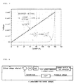
- FIG. 9 is a diagram showing the results of measuring the continuous critical current of a BSCCO tape from among high-temperature superconducting tapes, wherein measurement speed is set to 200m/h.
- the critical current of the superconducting tape is not measured as only an average value within a specific section, but is measured in real time as a continuous critical current appearing over the specific section or all sections of the superconducting tape, thus enabling the critical current to be promptly and accurately measured.
- the present invention is advantageous in that current is applied using wheel-type current terminals and voltage is measured using wheel-type voltage terminals while a superconducting tape is continuously supplied by a reel-to-reel device, thus continuously measuring critical current without burning out the superconducting tape, and in that the characteristics of critical current can be measured using inside voltage terminals between current terminals and voltage can also be measured in all sections in which current is being conducted because outside voltage terminals are provided, thus preventing the superconducting tape from burning out.
- the present invention is advantageous in that contact resistance with current terminals and voltage terminals can be minimized and conduction current can be increased thanks to a brush-type current lead-in structure and a brush-type voltage measurement structure, thereby enabling the supply of stable current and the accurate measurement of voltage.
- the present invention is configured such that it not only can measure critical current in a specific section while moving a superconducting tape at regular time intervals, but also can measure the critical current of a long superconducting tape while continuously moving the superconducting tape. Therefore, there are advantages in that the time required for the measurement of critical current is reduced, so that production costs can be reduced while production efficiency can be improved, and in that the local critical current of a superconducting tape is measured, so that critical current can be accurately measured while the superconducting tape can be protected.
Landscapes
- Physics & Mathematics (AREA)
- General Physics & Mathematics (AREA)
- Chemical & Material Sciences (AREA)
- Condensed Matter Physics & Semiconductors (AREA)
- Health & Medical Sciences (AREA)
- Life Sciences & Earth Sciences (AREA)
- Analytical Chemistry (AREA)
- Biochemistry (AREA)
- General Health & Medical Sciences (AREA)
- Electrochemistry (AREA)
- Immunology (AREA)
- Pathology (AREA)
- Chemical Kinetics & Catalysis (AREA)
- Measurement Of Current Or Voltage (AREA)
- Investigating Or Analyzing Materials By The Use Of Electric Means (AREA)
- Superconductors And Manufacturing Methods Therefor (AREA)
Description
- The present invention relates, in general, to an apparatus for measuring the critical current of a superconducting tape, and, more particularly, to a continuous critical current measurement apparatus, which can continuously measure the critical current of a superconducting tape using wheel-type current and voltage terminals without burning out the superconducting tape while continuously supplying the superconducting tape using a reel-to-reel device.
- Further, the present invention relates to a method of continuously measuring the critical current of a superconducting tape, which measures the current, required to control the voltage of a superconducting tape at 0.1 mV per meter, as critical current by moving the superconducting tape at regular time intervals using a continuous critical current measurement apparatus, thus reducing the time required for the measurement of critical current and accurately measuring the critical current.
- At this time when the industrialization of superconducting tapes (or wires) is ongoing, fast manufacturing speed is required, a fast and accurate measurement method of determining the quality of superconducting tapes is required in conjunction with the fast manufacturing speed, and a method of promptly and accurately measuring the quality of superconducting tapes without causing damage to (burning out) the superconducting tapes is also required.
- A conventional method of measuring the critical current of a superconducting tape is a four-terminal critical current measurement method, which is configured such that two current terminals are arranged on a superconducting tape and voltage terminals are interposed between the current terminals, and current is conducted to the current terminals, thus measuring the critical current of the superconducting tape.
- Since such a method allows current to be directly conducted to the tape, relatively accurate critical current can be obtained. However, such a method is disadvantageous in that a superconducting tape may easily burn out due to overcurrent occurring during the measuring of critical current, a load applied to the tape on account of current and voltage terminals, and a soldering operation performed when the terminals for measurement are formed. Further, such a method is unsuitable for measuring the critical current of a long tape. Therefore, in order to measure the critical current of a long tape, a contact critical current measurement method, which measures the voltage while allowing current to flow into the tape by means of physical contact of individual terminals without soldering, must be introduced.
- As a conventional method of measuring the critical current of a long tape, two types of methods have been mainly used.
- A first type is a scheme for measuring the critical current of a superconducting tape in a batch type, and is configured such that the superconducting tape is caused to pass through a space between two superconducting tape guide rollers disposed in a liquid nitrogen container. Further, a support is formed below the superconducting tape so as to prevent the tape from hanging down. Further, to measure critical current based on a four-terminal method, four terminals are sequentially arranged on a high-temperature superconducting tape as a (+) current terminal, a (+) voltage terminal, a (-) voltage terminal and a (-) current terminal, respectively, so that when the terminals are moved downwards from above and come into contact with the superconducting tape, the voltage of the superconducting tape is measured at the voltage terminals while current is flowing through the current terminals.
- A second type is an apparatus for measuring critical current while continuously supplying a tape along guide rollers, and is configured such that a superconducting tape passes through a space between the guide rollers disposed in a liquid nitrogen container. Here, one guide roller also serves as a (+) current terminal and the other guide roller also serves as a (-) current terminal. In this way, the guide rollers not only feed the superconducting tape, but also serve to apply current to the superconducting tape. Therefore, in order to measure voltage in the state in which the superconducting tape is moving, separate terminals are required. A roller for a (+) voltage terminal and a roller for a (-) voltage terminal serve as voltage terminals. In order to use a continuous critical current measurement apparatus, contact resistance can be reduced only when the force of contact between the superconducting tape guide rollers and the superconducting tape must be increased by strongly pulling the superconducting tape disposed between the superconducting tape guide rollers. Therefore, this method is suitable for the measurement of the critical current of a high-strength superconducting tape.
- However, since high-temperature superconducting tapes which have been developed to date use silver (Ag) or an alloy of silver as the outer surfaces thereof, they are of low strength. Therefore, due to the low-strength characteristics of superconducting tapes, it is almost impossible to use a continuous critical current measurement apparatus, and thus a batch-type critical current measurement apparatus must be used.
- Further, a conventional batch-type critical current measurement apparatus is capable of measuring critical current (lc) only in a contact manner, and uses pressure applied to current and voltage terminals as an important variable. That is, during a procedure for applying pressure to ensure a sufficiently large contact area in the current terminals for current conduction, a superconducting tape may burn out due to overpressure. Further, when the pressure is excessively low, measurement errors occur due to contact resistance when the current is conducted. Further, similarly to the voltage terminal, when applied pressure is excessively low, noise may occur during voltage measurement, whereas when applied pressure is excessively high, burning out of the superconducting tape may be caused. Therefore, a measurement apparatus capable of ensuring the accuracy and reliability of the measurement of critical current (lc) must be constructed.
- As related arts using such a batch-type critical current measurement apparatus and a continuous critical current measurement apparatus, there are patents disclosed in Korean Pat. No.
0513208 U.S. Pat. Nos. 5936394 and7554317B2 . - Those related arts do not disclose the measurement of continuous critical current in the strict sense. That is, in those patents, the critical current of a superconducting tape is not measured while the superconducting tape is continuously fed, but is measured in the state in which the feeding of the tape stops and both a planar terminal capable of applying current and another planar terminal for measuring voltage press the superconducting tape at the time of measuring critical current. If a long superconducting tape is measured, an operation of raising and lowering a current or voltage terminal must be repeated in such a go-and-stop manner, and thus there is a disadvantage in that a lot of time is required for the measurement of critical current especially for a long superconducting tape. Further, those patents are problematic in that, since average critical current is measured, local defects cannot be found, so that the characteristics of a superconducting tape are not properly evaluated, and measurement resolution is limited. Furthermore, in the case of technology disclosed in
U.S. Pat. No. 7554317B2 , since a current terminal is formed to be of a wheel type, current can be continuously applied, but a voltage terminal is not formed to be of a wheel type, thus making it impossible to properly perform continuous processing. - In addition, in those conventional schemes, current is supplied mainly in a line contact manner to guide rollers or wheel-type terminals which are used for the feeding of a superconducting tape and are used as voltage or current terminals, and thus there are advantageous in that conduction current is not high and contact resistance is large due to an increase in rotational friction.
- Furthermore, the conventional schemes are disadvantageous in that the force of contact between the superconducting tape and the current and voltage terminals decreases, thus increasing contact resistance, and in that it is impossible to measure voltage between current and voltage terminals, thus making it difficult to measure critical currents on all areas of the superconducting tape.
- Accordingly, the present invention has been made keeping in mind the above problems occurring in the prior art, and an object of the present invention is to provide a continuous critical current measurement apparatus, which can continuously measure the critical current of a superconducting tape using wheel-type current and voltage terminals without burning out the superconducting tape while continuously supplying the superconducting tape using a reel-to-reel device.
- Another object of the present invention is to provide a continuous critical current measurement apparatus, which not only can measure critical current using voltage terminals disposed between current terminals but also can measure voltages in all sections in which current is being conducted because voltage terminals are also provided outside the current terminals.
- A further object of the present invention is to provide a continuous critical current measurement method, which measures current, required to control voltage of a superconducting tape at 0.1 mV per meter while moving the superconducting tape at regular time intervals by using the continuous critical current measurement apparatus, as critical current, thus shortening the time required for the measurement of the critical current and accurately measuring the critical current.
- In order to accomplish the above objects, the present invention provides a continuous critical current measurement apparatus for measuring critical current of a superconducting tape while feeding the superconducting tape in a liquid nitrogen container, comprising wheel-type current terminals; and wheel-type voltage terminals, wherein the superconducting tape is continuously supplied and fed by a reel-to-reel device, and the critical current of the superconducting tape is measured in real time using the wheel-type current terminals and the wheel-type voltage terminals while the superconducting tape is fed at constant linear velocity in contact with the wheel-type current terminals and the wheel-type voltage terminals.
- Preferably, each of the voltage terminals comprises an inside voltage terminal disposed inside a corresponding current terminal with respect to a feeding path of the superconducting tape and an outside voltage terminal disposed outside the corresponding current terminal with respect to the feeding path.
- Preferably, the continuous critical current measurement apparatus further comprises a supporting bar or a supporting roller formed between the inside voltage terminals and configured to support the superconducting tape that is fed.
- Preferably, the continuous critical current measurement apparatus further comprises a plurality of feed reels formed between the inside voltage terminals and configured to allow the superconducting tape to be wound around the feed reels in multiple turns, thus enabling critical current corresponding to a length of the wound superconducting tape to be measured.
- Preferably, the superconducting tape in contact with the current terminals is fed in contact with more than a half of a circumference of each of the current terminals.
- Preferably, the superconducting tape in contact with the voltage terminals is fed in a direction having a slope less than that of a tangent line at a point of a contact end of the superconducting tape in contact with the current terminals.
- Preferably, each of the current terminals and the voltage terminals is formed as a wheel type terminal, and is configured such that a tape receiving groove is formed along a circumference of the current or voltage terminal and such that a brush contact part is formed to protrude backwards from a center portion of the current or voltage terminal and is configured to apply current and measure voltage. Further, the current terminals and the voltage terminals are configured to perform current application and voltage measurement using a brush-type current lead-in structure and a brush-type voltage measurement structure, respectively.
- In this case, each of the brush-type current lead-in structure and the brush-type voltage measurement structure comprises one or more brush parts formed in contact with the brush contact part to correspond to a curvature of the brush contact part; and conducting wire parts connected to an external terminal so as to apply current to the brush parts or measure voltage at the brush parts. The brush parts are connected to each other as one pair by a spring, thus adjusting contact pressures of the brush parts.
- Preferably, each of the brush-type current lead-in structure and the brush-type voltage measurement structure comprises brush parts formed in contact with the brush contact part to correspond to a curvature of the brush contact part, and formed as at least one pair; control arms respectively connected to the brush parts of the pair to form a predetermined angle therebetween and connected to each other by a spring, thus adjusting contact pressures of the brush parts and balancing the brush parts; and conducting wire parts inserted into the control arms through first ends of the control arms and electrically connected to the brush parts, thus supplying current.
- Preferably, the superconducting tape is fed at constant velocity by a velocity control unit.
- Preferably, reference voltage is applied to the superconducting tape, current generated by the reference voltage is set to the critical current, and current is bypassed to a bypass shunt when abnormal current occurs.
- Further, the present invention provides a continuous critical current measurement method, comprising inputting voltage at both ends of the superconducting tape, which is measured at the voltage terminals, to a Digital Signal Processor (DSP) through an amplifier and an Analog Digital Converter (ADC) by using the continuous critical current measurement apparatus, thus measuring voltage at both ends of the superconducting tape; applying current to the current terminals while controlling a current source via a Digital Analog Converter (DAC) so as to maintain the measured voltage at 0.1 mV per meter; and measuring the current applied to the current terminals and tracking current, which is applied to maintain the voltage at 0.1 mV per meter, thus measuring critical current of the superconducting tape, wherein the voltage measured at the voltage terminals is proportional to an n-th power of the current, so that the critical current is linearized by obtaining an 1/n-th power (where n = 10∼40) of the measured voltage, thus supplying the linearized critical current to the DAC.
- The above and other objects, features and advantages of the present invention will be more clearly understood from the following detailed description taken in conjunction with the accompanying drawings, in which:
-
FIG. 1 is a diagram showing the construction of principal components of a continuous critical current measurement apparatus according to the present invention; -
FIG. 2 is a sectional view of the current terminal or voltage terminal of the continuous critical current measurement apparatus according to the present invention; -
FIG. 3 is a diagram showing the brush-type current lead-in structure or brush-type voltage measurement structure of the continuous critical current measurement apparatus according to an embodiment of the present invention; -
FIG. 4 is a diagram showing the brush-type current lead-in structure or brush-type voltage measurement structure of the continuous critical current measurement apparatus according to another embodiment of the present invention; -
FIG. 5 is a perspective view of the feed reel of the continuous critical current measurement apparatus according to the present invention; -
FIG. 6 is a block diagram showing the schematic construction of the continuous critical current measurement apparatus and a continuous critical current measurement method according to the present invention; -
FIG. 7 is a diagram showing formulas for linearizing non-linear critical current; -
FIG. 8 is a flow diagram showing a control algorithm for measuring the continuous critical current of a superconducting tape using a Digital Signal Processor (DSP); and -
FIG. 9 is a diagram showing the results of measurement of the continuous critical current of a Bismuth Strontium Calcium Copper Oxide (BSCCO) tape. - Hereinafter, embodiments of an apparatus for measuring the critical current of a superconducting tape according to the present invention will be described in detail with reference to the attached drawings.
-
FIG. 1 is a diagram showing the construction of principal components of a continuous critical current measurement apparatus according to the present invention,FIG. 2 is a sectional view of the current terminal or voltage terminal of the continuous critical current measurement apparatus according to the present invention,FIG. 3 is a diagram showing the brush-type current lead-in structure or brush-type voltage measurement structure of the continuous critical current measurement apparatus according to an embodiment of the present invention,FIG. 4 is a diagram showing the brush-type current lead-in structure or brush-type voltage measurement structure of the continuous critical current measurement apparatus according to another embodiment of the present invention, andFIG. 5 is a perspective view of the feed reel of the continuous critical current measurement apparatus according to the present invention; - The present invention relates to an apparatus capable of continuously measuring the critical current of a
superconducting tape 10, in particular, along superconducting tape 10 supplied by a reel-to-reel device, and is configured to continuously measure the critical current of thesuperconducting tape 10 while feeding thesuperconducting tape 10 in a liquid nitrogen container. - In this case, the term "reel-to-reel device" means a device which includes a
supply reel 20 for supplying thesuperconducting tape 10 and a windingreel 30 for winding thesuperconducting tape 10, the measurement of the characteristics of which has been completed, and in which a motor rotating at constant speed is connected to the windingreel 30 to enable thesuperconducting tape 10 to be fed at constant linear velocity. - The
supply reel 20 and the windingreel 30 need not be accommodated in the liquid nitrogen container. Thesuperconducting tape 10 is rotated while the tension thereof is controlled to correspond to a certain tension value applied to the motor. Avelocity control unit 530 such as an encoder is formed to be adjacent to thesupply reel 20 or the windingreel 30 so as to measure the feed distance and velocity of thesuperconducting tape 10 in real time and feed thesuperconducting tape 10 at constant velocity. - In this way, while the
superconducting tape 10 is continuously supplied and fed by the reel-to-reel device, wheel-typecurrent terminals 100 and wheel-type voltage terminals 200 are formed on a path along which thesuperconducting tape 10 moves and which is disposed between thesupply reel 20 and the windingreel 30. Accordingly, critical current can be measured in real time while thesuperconducting tape 10 is in contact with thecurrent terminals 100 and thevoltage terminals 200 and is fed at constant linear velocity. This structure measures critical current by winding thesuperconducting tape 10 instead of pressing it, thereby preventing thesuperconducting tape 10 from burning out. - All components of the reel-to-reel device for the measurement of critical current are formed to be fixed on a Fiber-Reinforced Plastic (FRP) plate or the like made of an insulating material which is chemically stabilized even if it is immersed in liquid nitrogen. At the time of measuring critical current, the inside of the reel-to-reel device is tightly shut from the outside thereof, and the FRP plate to which all of the components are fixed is immersed below the encoders in the liquid nitrogen container, and thus the critical current is measured.
- Basically, the critical current according to the present invention is measured by a four-terminal method in such a way that (+) and (-)
current terminals 100 are formed at both ends of any section of thesuperconducting tape 10 and (+) and (-)voltage terminals 200 are formed between thecurrent terminals 100, so that voltage corresponding to the applied current is measured, and then the critical current is measured. - Further, the
current terminals 100 are wheels for transmitting current to thesuperconducting tape 10 so as to measure the conduction characteristics and critical current of thesuperconducting tape 10, and are made of copper (Cu) coated with gold (Au). Thevoltage terminals 200 are wheels for measuring voltage generated at thesuperconducting tape 10, and are made of stainless steel or the like which is a metal having corrosion resistance. - Furthermore, each of the
voltage terminals 200 includes aninside voltage terminal 210 disposed inside thecurrent terminal 100 with respect to the feeding path of thesuperconducting tape 10, and anoutside voltage terminal 220 disposed outside thecurrent terminal 100 with respect to the feeding path. Theinside voltage terminals 210 are configured to measure the critical current of thesuperconducting tape 10 which is being fed therebetween, and theoutside voltage terminals 220 are configured to measure the critical current in regions between theinside voltage terminals 210 and thecurrent terminals 100. Generally, the four-terminal method implemented by thecurrent terminals 100 and theinside voltage terminals 210 can measure only the critical current between theinside voltage terminals 210. When a defect is present on thesuperconducting tape 10 disposed between theinside voltage terminals 210 and thecurrent terminals 100, thesuperconducting tape 10 may burn out because the defect at that location cannot be found. Therefore, each of theoutside voltage terminals 220 is configured such that a voltage terminal is installed even outside a correspondingcurrent terminal 100 to enable voltage to be measured in all sections in which current is being conducted, thus preventing thesuperconducting tape 10 from burning out. - Further, the
superconducting tape 10 in contact with thecurrent terminals 100 is fed in contact with more than a half of the circumference of each of thecurrent terminals 100, so that current is stably supplied to thesuperconducting tape 10. In this case, eachvoltage terminal 200 is disposed inside thecurrent terminal 100 with respect to the feeding path of thesuperconducting tape 10, so that thesuperconducting tape 10 in contact with thevoltage terminal 200 is fed at an angle (in a direction) less than the slope of a tangent line at a point of the contact end of thesuperconducting tape 10 in contact with thecurrent terminal 100. That is, thesuperconducting tape 10 is supplied to thecurrent terminal 100 after being bent by theoutside voltage terminal 220 at a predetermined angle, and is fed after being bent by theinside voltage terminal 210 at a predetermined angle. This is intended to stably apply current and measure voltage by inducing stable contact force between thesuperconducting tape 10 with thevoltage terminal 200 and with thecurrent terminal 100. - Meanwhile, as shown in
FIG. 2 , each of thecurrent terminal 100 and thevoltage terminal 200 is formed as a wheel type terminal, and is configured such that atape receiving groove 310 is formed along the circumference of the current or voltage terminal and abrush contact part 320 is formed to protrude backwards from a center portion of the current or voltage terminal so as to apply current and measure voltage. That is, each of thecurrent terminal 100 and thevoltage terminal 200 is formed in a disc shape rotating around a shaft in its entirety. Thetape receiving groove 310 is formed along the circumference of the current or voltage terminal to receive thesuperconducting tape 10 and come into contact with thesuperconducting tape 10. The cylindricalbrush contact part 320 is formed to protrude backwards from the current or voltage terminal to allow abrush part 420, which will be described later, to come into contact with thebrush contact part 320. Accordingly, constant current can be stably applied regardless of the rotation of thecurrent terminal 100 and thevoltage terminal 200, thus minimizing contact resistance. - Supporting bars or supporting
rollers 510 for supporting thesuperconducting tape 10 which is fed are further formed between thecurrent terminals 100, precisely, between theinside voltage terminals 210. These are intended to prevent along superconducting tape 10 from hanging down at the time of measuring the critical current of the long superconducting tape because thelong superconducting tape 10 may hang down when the distance between theinside voltage terminals 210 is excessively long. - Further, it is preferable that the application of current to each
current terminal 100 and the measurement of voltage using eachvoltage terminal 200 be performed by a brush-type current lead-in structure and a brush-type voltage measurement structure, respectively. The brush-type current lead-in and voltage measurement structures allowbrush parts 410 for conduction to come into surface contact with thebrush contact part 320 of each of thecurrent terminal 100 and thevoltage terminal 200, and enable the application of constant current and the accurate measurement of voltage to be performed regardless of the rotation of each terminal. The brush-type current lead-in structure applies current to the edge of thecurrent terminal 100 adjacent to thesuperconducting tape 10 without applying current to the central axis of thecurrent terminal 100, thus minimizing current loss and enabling a more accurate current value to be applied to thecurrent terminal 100. - In an embodiment of the brush-type current lead-in structure, the
current terminal 100 includes one ormore brush parts 410 and conductingwire parts 430, as shown inFIG. 3 . Thebrush parts 410 are formed in contact with thebrush contact part 320 to correspond to the curvature of thebrush contact part 320, and theconducting wire parts 430 are connected to an external terminal to apply current to thebrush parts 410, thereby applying current to thecurrent terminal 100 through thebrush parts 410. Further, thebrush parts 410 of thecurrent terminal 100 are formed as pairs according to the circumstances, and twobrush parts 410 of each pair are connected to each other by a spring, so that the contact pressures of thebrush parts 410 with thebrush contact part 320 of thecurrent terminal 100 can be adjusted. In other words, thebrush parts 410 may be formed in a plural number according to current capacity. Thebrush parts 410 are formed as pairs with thebrush parts 410 fixed on an FRP plate, and are connected to each other by springs. Therefore, the contact pressures of thebrush parts 410 with thebrush contact part 320 of thecurrent terminal 100 can be adjusted while being balanced when thecurrent terminal 100 is rotating. Of course, this structure may also be applied to the brush-type voltage measurement structure. - Further, in an embodiment of the brush-type voltage measurement structure, as shown in
FIG. 4 , thevoltage terminal 200 includesbrush parts 410, controlarms 420, and conductingwire parts 430. Thebrush parts 410 are formed in contact with abrush contact part 320 to correspond to the curvature of thebrush contact part 320 and are also formed as at least one pair. Thecontrol arms 420 are respectively connected to thebrush parts 410, which are fixed on the FRP plate and are formed as a pair, to form a predetermined angle therebetween. Thecontrol arms 420 are connected to each other by a spring and are configured to adjust the contact pressures of thebrush parts 410 and to balance the contact pressures. Theconducting wire parts 430 are inserted into therespective control arms 420 through the first ends of thecontrol arms 420 and are electrically connected to thebrush parts 410, thus supplying current to thebrush parts 410. The voltage is measured at thevoltage terminal 200 through thebrush parts 410. That is, thebrush parts 410 are formed at the ends of the twocontrol arms 420, and thecontrol arms 420 are connected to each other by a spring, like elastic nippers, thus inducing uniform contact pressures of thebrush parts 410 with thebrush contact part 320. Of course, this structure may also be applied to the brush-type current lead-in structure. - In particular, in the brush-type current lead-in structure in contact with the
current terminal 100, at least two (two, four or six)brush parts 410 are formed, so that the contact area of thebrush parts 410 with thebrush contact part 320 is increased, and thus contact resistance is decreased and conduction current is increased. The twobrush parts 410 forming a pair enable the contact pressures thereof to be adjusted by the spring, thus decreasing rotational friction between thecurrent terminal 100 and thebrush parts 410. Further, in the brush-type voltage measurement structure in contact with thecurrent terminal 100, about twobrush parts 410 are preferably formed to accurately and stably measure voltage. Theconducting wire parts 430 are connected to therespective brush parts 410, but are combined and connected to an external terminal for voltage measurement as a singleconducting wire part 430. - In this case, the
brush parts 410 are configured to supply current to thecurrent terminal 100 that is rotating and to measure voltage at thevoltage terminal 200 that is rotating, and are made of a metallic material having small rotational friction and low contact resistance, for example, an alloy of carbon and copper. - Further, as shown in
FIG. 5 , a plurality of (two inFIG. 5 ) feedreels 520 is formed between theinside voltage terminals 210 and is configured to allow thesuperconducting tape 10 to be wound around thefeed reels 520 in multiple turns, so that critical current corresponding to the length of thewound superconducting tape 10 can be measured, and the critical current of even along superconducting tape 10 can also be measured. That is, when a plurality offeed reels 520, for example, a total of fourfeed reels 520 including two upper feed reels and two lower feed reels, are formed between theinside voltage terminals 210, and thesuperconducting tape 10 is fed while being wound around the feed reels in multiple turns, thelong superconducting tape 10 having a length corresponding to the multiple turns is present between theinside voltage terminals 210, and thus the critical current is measured at both theinside voltage terminals 210. A detailed construction thereof is disclosed in detail in Korean Pat. Appln. No.10-2007-0110228 - Meanwhile, reference voltage is applied to the
superconducting tape 10, and current generated by the reference voltage is set to critical current. When abnormal current occurs, that is, when a sudden decrease in critical current, disconnection of a tape, or current caused by resistance higher than resistance at reference voltage occurs, the current is allowed to be bypassed to abypass shunt 540, thus preventing thesuperconducting tape 10 from burning out. - As described above, current is applied by the wheel-type
current terminals 100 and voltage is measured at the wheel-type voltage terminals 200 while thesuperconducting tape 10 is continuously supplied by the reel-to-reel device, so that the critical current of thesuperconducting tape 10 can be continuously measured without burning out thesuperconducting tape 10. Further, the present invention not only can measure the characteristics of critical current by using theinside voltage terminals 210 between thecurrent terminals 100, but also can measure voltage in all sections in which current is being conducted because theoutside voltage terminals 220 are provided, thus preventing thesuperconducting tape 10 from burning out. - Further, contact resistance with the
current terminals 100 and thevoltage terminals 200 can be minimized and conduction current can be increased by the brush-type current lead-in structure and the brush-type voltage measurement structure, thus enabling the supply of stable current and the accurate measurement of voltage. - Next, a continuous critical current measurement method using the continuous critical current measurement apparatus will be described in detail with reference to the attached drawings.
- The method of the present invention is configured to automatically measure critical current using the continuous critical current measurement apparatus in such a way that a Digital Signal Processor (DSP) controls voltage of a superconducting tape at 1µV per meter by moving the superconducting tape at regular time intervals. By this method, the time required for the measurement of critical current is reduced, so that production costs can be reduced while production efficiency can be improved, and the accurate measurement of critical current can be performed.
-
FIG. 6 is a block diagram showing the schematic construction of the continuous critical current measurement apparatus to describe the continuous critical current measurement method of the present invention and showing the continuous critical current measurement method using the schematic construction,FIG. 7 is a diagram showing formulas for linearizing non-linear critical current,FIG. 8 is a diagram showing a control algorithm for measuring the continuous critical current of a superconducting tape using a DSP, andFIG. 9 is a diagram showing the results of measurement of the continuous critical current of a Bismuth Strontium Calcium Copper Oxide (BSCCO) tape. - As shown in the drawings, the present invention proposes an apparatus for measuring the continuous critical current of a superconducting tape. The apparatus of the present invention employs a scheme in which wheel-type voltage terminals are installed at regular intervals of the superconducting tape immersed in liquid nitrogen, for example, at intervals of 1 m in this embodiment, and wheel-type current terminals are respectively installed outside the voltage terminals, and in which voltage corresponding to applied current is measured and critical current is then measured.
- The voltage at both ends of the superconducting tape which is measured at the voltage terminals is input to the DSP through an amplifier and an Analog Digital Converter (ADC), and consequently the voltage at both ends of the superconducting tape is measured. In order to maintain the measured voltage at 0.1 mV per meter, the current is applied to the current terminals while a current source is controlled via a Digital Analog Converter (DAC). Such an applied current is measured, so that the current value applied to maintain the voltage at 0.1 mV per meter is tracked, and as a result, the critical current can be measured. This shows that the instantaneous measurement of continuous critical current is implemented in an interval of at least 1 m. When this process is performed while the superconducting tape is continuously fed, the measurement of the continuous critical current of a long superconducting tape can be performed within a short period of time. Further, when the length to be measured is set to 0.5m, the voltage is controlled to be maintained at 0.05mV per 0.5m. In this case, it is possible to measure critical current to be twice as dense as that of the superconducting tape of 1 m at the same measurement speed as that of the superconducting tape of 1 m.
- Meanwhile, since the voltage measured at the voltage terminals is proportional to the n-th power of current, the 1/n-th power (n = 10∼40) of the measured voltage is obtained to linearize the critical current and the linearized current is supplied to the DAC, and thus the critical current can be measured by linearly varying current corresponding to sudden voltage variation.
- This process will be described in detail. The critical current of a superconducting tape is calculated by the following Equation (1),

where V is measured voltage, Ic is critical current, Vc is voltage at that time, and n is a value of 10∼40 in general in the case of a high-temperature superconducting tape. Referring to Equation (1), since voltage at both ends of the superconducting tape is proportional to the n-th power of the current, it may be difficult to control this voltage using a typical Proportional-Integral (Pl) controller. Therefore, when a value of k which causes the measured voltage to be identical to the voltage controlled at 0.1 mV per meter is obtained by calculating the 1/n-th power of the measured voltage, the linearization of current is possible, as shown in the blue line ofFIG. 7 , thus enabling control to be performed by the Pl controller. Here, when Vc is 0.0001 V (0.1 mV) and n is 30, a value of k (k =0.0001/0.00011/30) is obtained to have the value shown inFIG. 7. FIG. 8 is a diagram showing a control algorithm for measuring the continuous critical current of a superconducting tape using the DSP. InFIG. 8 , a linearized value of critical current is input to the Pl controller, is input to the DAC, and is then transferred to a current source. From the current source, the current is supplied to the superconducting tape so that 0.1 mV per meter is maintained. -
FIG. 9 is a diagram showing the results of measuring the continuous critical current of a BSCCO tape from among high-temperature superconducting tapes, wherein measurement speed is set to 200m/h. As shown in the drawing, the critical current of the superconducting tape is not measured as only an average value within a specific section, but is measured in real time as a continuous critical current appearing over the specific section or all sections of the superconducting tape, thus enabling the critical current to be promptly and accurately measured. - As described above, the present invention is advantageous in that current is applied using wheel-type current terminals and voltage is measured using wheel-type voltage terminals while a superconducting tape is continuously supplied by a reel-to-reel device, thus continuously measuring critical current without burning out the superconducting tape, and in that the characteristics of critical current can be measured using inside voltage terminals between current terminals and voltage can also be measured in all sections in which current is being conducted because outside voltage terminals are provided, thus preventing the superconducting tape from burning out.
- Further, the present invention is advantageous in that contact resistance with current terminals and voltage terminals can be minimized and conduction current can be increased thanks to a brush-type current lead-in structure and a brush-type voltage measurement structure, thereby enabling the supply of stable current and the accurate measurement of voltage.
- Furthermore, the present invention is configured such that it not only can measure critical current in a specific section while moving a superconducting tape at regular time intervals, but also can measure the critical current of a long superconducting tape while continuously moving the superconducting tape. Therefore, there are advantages in that the time required for the measurement of critical current is reduced, so that production costs can be reduced while production efficiency can be improved, and in that the local critical current of a superconducting tape is measured, so that critical current can be accurately measured while the superconducting tape can be protected.
- Although the preferred embodiments of the present invention have been disclosed for illustrative purposes, those skilled in the art will appreciate that various modifications, additions and substitutions are possible, without departing from the scope and spirit of the invention as disclosed in the accompanying claims.
Claims (14)
- A continuous critical current measurement apparatus for measuring critical current of a superconducting tape (10) while feeding the superconducting tape (10) in a liquid nitrogen container, comprising:wheel-type current terminals (100); andwheel-type voltage terminals (210, 220),wherein the apparatus is configured such that the superconducting tape is continuously supplied and fed by a reel-to-reel device, and the critical current of the superconducting tape is measured in real time using the wheel-type current terminals (100) and the wheel-type voltage terminals (210, 220) while the superconducting tape is fed at constant linear velocity in contact with the wheel-type current terminals (100) and the wheel-type voltage terminals (210,220).
- The continuous critical current measurement apparatus according to claim 1, wherein each of the voltage terminals comprises an inside voltage terminal (210) disposed inside a corresponding current terminal with respect to a feeding path of the superconducting tape and an outside voltage terminal (220) disposed outside the corresponding current terminal with respect to the feeding path.
- The continuous critical current measurement apparatus according to claim 2, further comprising a supporting bar (520) or a supporting rollers (510) formed between the inside voltage terminals and configured to support the superconducting tape that is fed.
- The continuous critical current measurement apparatus according to claim 2, further comprising a plurality of feed reels (510) formed between the inside voltage terminals and configured to allow the superconducting tape to be wound around the feed reels (510) in multiple turns, thus enabling critical current corresponding to a length of the wound superconducting tape to be measured.
- The continuous critical current measurement apparatus according to claim 1, wherein the superconducting tape in contact with the current terminals (100) is fed in contact with more than a half of a circumference of each of the current terminals.
- The continuous critical current measurement apparatus according to claim 5, wherein the superconducting tape in contact with the voltage terminals (200) is fed in a direction having a slope less than that of a tangent line at a point of a contact end of the superconducting tape in contact with the current terminals.
- The continuous critical current measurement apparatus according to claim 1, wherein each of the current terminals (100) and the voltage terminals (200) is formed as a wheel type terminal, and is configured such that a tape receiving groove (310) is formed along a circumference of the current or voltage terminal and such that a brush contact part is formed to protrude backwards from a center portion of the current or voltage terminal and is configured to apply current and measure voltage.
- The continuous critical current measurement apparatus according to claim 7 wherein the current terminals (100) and the voltage terminals (200) are configured to perform current application and voltage measurement using a brush-type current lead-in structure and a brush-type voltage measurement structure, respectively.
- The continuous critical current measurement apparatus according to claim 8, wherein each of the brush-type current lead-in structure and the brush-type voltage measurement structure comprises :one or more brush parts (410) formed in contact with the brush contact part to correspond to a curvature of the brush contact part; andconducting wire parts connected to an external terminal so as to apply current to the brush parts (410) or measure voltage at the brush parts (410).
- The continuous critical current measurement apparatus according to claim 9, wherein the brush parts (410) are connected to each other as one pair by a spring, thus adjusting contact pressures of the brush parts.
- The continuous critical current measurement apparatus according to claim 8, wherein each of the brush-type current lead-in structure and the brush-type voltage measurement structure comprises:brush parts (410) formed in contact with the brush contact part to correspond to a curvature of the brush contact part, and formed as at least one pair;control arms (420) respectively connected to the brush parts (410) of the pair to form a predetermined angle therebetween and connected to each other by a spring, thus adjusting contact pressures of the brush parts and balancing the brush parts; andconducting wire parts (430) inserted into the control arms (420) through first ends of the control arms (420) and electrically connected to the brush parts, thus supplying current.
- The continuous critical current measurement apparatus according to claim 1, wherein the superconducting tape (10) is fed at constant velocity by a velocity control unit.
- The continuous critical current measurement apparatus according to claim 1, wherein reference voltage is applied to the superconducting tape (10), current generated by the reference voltage is set to the critical current, and current is bypassed to a bypass shunt when abnormal current occurs.
- A continuous critical current measurement method, comprising:measuring voltage at both ends of a superconducting tape (10) using the continuous critical current measurement apparatus according to any one of claims 1 to 13 by inputting voltage at both ends of the superconducting tape, which is measured at the voltage terminals, to a Digital Signal Processor, DSP, through an amplifier and an Analog Digital converter, ADC;applying current to the current terminals (100) while controlling a current source via a Digital Analog Converter DAC so as to maintain the measured voltage at 0.1mv per meter; andmeasuring the current applied to the current terminals (100) and tracking current, which is applied to maintain the voltage at 0.1mV per meter, thus measuring critical current of the superconducting tape,wherein the voltage measured at the voltage terminals (200) is proportional to an n-th power of the current, so that the critical current is linearized by obtaining a 1/n-th power ,where n = 10~40, of the measured voltage, thus supplying the linearized critical current to the DAC.
Applications Claiming Priority (1)
| Application Number | Priority Date | Filing Date | Title |
|---|---|---|---|
| KR1020090123867A KR101048884B1 (en) | 2009-12-14 | 2009-12-14 | Continuous critical current measuring device |
Publications (2)
| Publication Number | Publication Date |
|---|---|
| EP2336797A1 EP2336797A1 (en) | 2011-06-22 |
| EP2336797B1 true EP2336797B1 (en) | 2012-10-03 |
Family
ID=43587149
Family Applications (1)
| Application Number | Title | Priority Date | Filing Date |
|---|---|---|---|
| EP10171803A Active EP2336797B1 (en) | 2009-12-14 | 2010-08-03 | Continuous critical current measurement apparatus and method of measuring continuous critical current using the same |
Country Status (5)
| Country | Link |
|---|---|
| US (1) | US8441247B2 (en) |
| EP (1) | EP2336797B1 (en) |
| JP (1) | JP5087104B2 (en) |
| KR (1) | KR101048884B1 (en) |
| ES (1) | ES2394399T3 (en) |
Families Citing this family (9)
| Publication number | Priority date | Publication date | Assignee | Title |
|---|---|---|---|---|
| DE102010011536A1 (en) * | 2009-09-10 | 2011-03-24 | Zenergy Power Gmbh | Method and apparatus for quality control of superconducting tapes |
| JP2013148440A (en) * | 2012-01-19 | 2013-08-01 | Furukawa Electric Co Ltd:The | Critical current inspection device and critical current inspection method |
| CN104133100A (en) * | 2014-07-14 | 2014-11-05 | 上海超导科技股份有限公司 | Device and method for continuously measuring critical current of high-temperature superconducting tape |
| CN107505493B (en) * | 2016-11-04 | 2023-09-26 | 洛阳理工学院 | A tension-controllable critical current measuring device for superconducting strips |
| WO2019206758A1 (en) * | 2018-04-25 | 2019-10-31 | Basf Se | Apparatus for quality control of a superconducting tape |
| CN110703165B (en) * | 2019-10-08 | 2020-09-04 | 上海交通大学 | Device and method for testing turning diameter of superconducting strip |
| CN114166741A (en) * | 2021-12-09 | 2022-03-11 | 上海超导科技股份有限公司 | Device and method for testing delamination stress of superconducting strip |
| CN114839488B (en) * | 2022-05-07 | 2022-12-09 | 上海超导科技股份有限公司 | System and method for judging overcurrent impact resistance of superconducting strip |
| WO2024215355A2 (en) * | 2022-11-03 | 2024-10-17 | The Florida State University Research Foundation, Inc. | Force magnetometer for reel-to-reel assessment of superconducting tapes |
Family Cites Families (13)
| Publication number | Priority date | Publication date | Assignee | Title |
|---|---|---|---|---|
| US5134360A (en) * | 1991-03-15 | 1992-07-28 | The United States Of America As Represented By The United States Department Of Energy | Apparatus and method for critical current measurements |
| JPH102890A (en) | 1996-06-14 | 1998-01-06 | Japan Organo Co Ltd | Performance evaluation method of cation exchange resin |
| JPH10197468A (en) * | 1997-01-13 | 1998-07-31 | Hitachi Cable Ltd | Method and apparatus for measuring critical current of superconducting wire |
| JP3171131B2 (en) * | 1997-02-25 | 2001-05-28 | 住友電気工業株式会社 | Method and apparatus for measuring critical current value of superconducting wire |
| DE19717283C1 (en) * | 1997-04-24 | 1998-04-23 | Karlsruhe Forschzent | Method of contact free longitudinal and transversal homogeneity examination of critical current density in strip supraconductors |
| WO2001004646A1 (en) * | 1999-07-13 | 2001-01-18 | Los Alamos National Laboratory | Apparatus for measurement of critical current in superconductive tapes |
| JP3360682B2 (en) * | 2000-10-20 | 2002-12-24 | 住友電気工業株式会社 | Apparatus for measuring critical current value of superconducting wire |
| JP4223744B2 (en) * | 2002-06-27 | 2009-02-12 | 住友電気工業株式会社 | Critical current measurement method for high temperature superconducting wire |
| KR100513208B1 (en) | 2002-12-24 | 2005-09-08 | 한국전기연구원 | Continuous critical current measurement system for high temperature superconducting tape |
| US7554317B2 (en) * | 2004-09-24 | 2009-06-30 | Superpower, Inc. | Critical current testing techniques for superconducting conductors |
| JP2007178340A (en) * | 2005-12-28 | 2007-07-12 | Sumitomo Electric Ind Ltd | Method for measuring critical current value of superconducting wire |
| KR100978353B1 (en) * | 2008-01-30 | 2010-08-30 | 주식회사 서남 | Apparatus and method for measuring critical current of superconducting wire |
| JP5066480B2 (en) * | 2008-05-07 | 2012-11-07 | 株式会社フジクラ | Critical current measuring device |
-
2009
- 2009-12-14 KR KR1020090123867A patent/KR101048884B1/en active Active
-
2010
- 2010-05-11 JP JP2010109026A patent/JP5087104B2/en active Active
- 2010-07-20 US US12/840,173 patent/US8441247B2/en active Active
- 2010-08-03 ES ES10171803T patent/ES2394399T3/en active Active
- 2010-08-03 EP EP10171803A patent/EP2336797B1/en active Active
Also Published As
| Publication number | Publication date |
|---|---|
| JP2011123046A (en) | 2011-06-23 |
| US8441247B2 (en) | 2013-05-14 |
| US20110140710A1 (en) | 2011-06-16 |
| EP2336797A1 (en) | 2011-06-22 |
| JP5087104B2 (en) | 2012-11-28 |
| KR101048884B1 (en) | 2011-07-13 |
| KR20110067316A (en) | 2011-06-22 |
| ES2394399T3 (en) | 2013-01-31 |
Similar Documents
| Publication | Publication Date | Title |
|---|---|---|
| US8441247B2 (en) | Continuous critical current measurement apparatus and method of measuring continuous critical current using the same | |
| US5936394A (en) | Method and apparatus for measuring critical current value of superconducting wire | |
| US20100227765A1 (en) | Method of Measuring Critical Current Value of Superconducting Wire | |
| KR20120111144A (en) | Critical current measurement devices under strain and stress | |
| JPH0539407B2 (en) | ||
| CN104914331A (en) | Measurement apparatus and measurement method for critical current and n value index of high-temperature superconductive tape | |
| KR20100032658A (en) | Apparatus for both critical current and defects measurement of hts conductor | |
| KR20160077635A (en) | Spiral bending test apparatus for superconducting wire | |
| CN114280514B (en) | Method and device for rapidly positioning critical current low point of superconducting strip | |
| JP7299005B2 (en) | Electrical resistance measuring device for conductive fiber thread | |
| CN113588715A (en) | Hall test device and method for large-size strip-shaped semiconductor sample | |
| CN102944735B (en) | Automatic test system and test method for thermoelectric forces of thermocouple wires | |
| JP3996830B2 (en) | Method and apparatus for measuring critical current characteristics of superconducting wire | |
| Sytnikov et al. | The 5 m HTS power cable development and test | |
| US2734858A (en) | Electroplating appabatus with | |
| JP3360682B2 (en) | Apparatus for measuring critical current value of superconducting wire | |
| KR101521718B1 (en) | Apparatus for critical transition temperature measurement using Hall array and method of the same | |
| JP2013032937A (en) | Superconducting wire critical current measuring apparatus and critical current measuring method | |
| KR101215533B1 (en) | local HTS wire critical current measurement method | |
| CN216013627U (en) | A four-lead method roll-to-roll transmission type superconducting long belt critical current testing device | |
| CN223307994U (en) | A cable tensile testing equipment | |
| JP2004311173A (en) | Dislocation segment conductor and superconducting cable | |
| CN108510856B (en) | A drum-type potentiometer teaching aid for physical experiments and its use method | |
| JP2012033525A (en) | Cooling baths and superconductive critical current measuring device | |
| SU1397745A1 (en) | Device for determining thermoelectric inhomogeneity of wire |
Legal Events
| Date | Code | Title | Description |
|---|---|---|---|
| PUAI | Public reference made under article 153(3) epc to a published international application that has entered the european phase |
Free format text: ORIGINAL CODE: 0009012 |
|
| AK | Designated contracting states |
Kind code of ref document: A1 Designated state(s): AL AT BE BG CH CY CZ DE DK EE ES FI FR GB GR HR HU IE IS IT LI LT LU LV MC MK MT NL NO PL PT RO SE SI SK SM TR |
|
| AX | Request for extension of the european patent |
Extension state: BA ME RS |
|
| 17P | Request for examination filed |
Effective date: 20111222 |
|
| RIC1 | Information provided on ipc code assigned before grant |
Ipc: G01R 33/12 20060101AFI20120117BHEP |
|
| GRAJ | Information related to disapproval of communication of intention to grant by the applicant or resumption of examination proceedings by the epo deleted |
Free format text: ORIGINAL CODE: EPIDOSDIGR1 |
|
| GRAP | Despatch of communication of intention to grant a patent |
Free format text: ORIGINAL CODE: EPIDOSNIGR1 |
|
| GRAP | Despatch of communication of intention to grant a patent |
Free format text: ORIGINAL CODE: EPIDOSNIGR1 |
|
| GRAS | Grant fee paid |
Free format text: ORIGINAL CODE: EPIDOSNIGR3 |
|
| GRAA | (expected) grant |
Free format text: ORIGINAL CODE: 0009210 |
|
| AK | Designated contracting states |
Kind code of ref document: B1 Designated state(s): AL AT BE BG CH CY CZ DE DK EE ES FI FR GB GR HR HU IE IS IT LI LT LU LV MC MK MT NL NO PL PT RO SE SI SK SM TR |
|
| REG | Reference to a national code |
Ref country code: GB Ref legal event code: FG4D |
|
| REG | Reference to a national code |
Ref country code: AT Ref legal event code: REF Ref document number: 578205 Country of ref document: AT Kind code of ref document: T Effective date: 20121015 Ref country code: CH Ref legal event code: EP |
|
| REG | Reference to a national code |
Ref country code: IE Ref legal event code: FG4D |
|
| REG | Reference to a national code |
Ref country code: DE Ref legal event code: R096 Ref document number: 602010003046 Country of ref document: DE Effective date: 20121129 |
|
| REG | Reference to a national code |
Ref country code: ES Ref legal event code: FG2A Ref document number: 2394399 Country of ref document: ES Kind code of ref document: T3 Effective date: 20130131 |
|
| REG | Reference to a national code |
Ref country code: AT Ref legal event code: MK05 Ref document number: 578205 Country of ref document: AT Kind code of ref document: T Effective date: 20121003 |
|
| PG25 | Lapsed in a contracting state [announced via postgrant information from national office to epo] |
Ref country code: SI Free format text: LAPSE BECAUSE OF FAILURE TO SUBMIT A TRANSLATION OF THE DESCRIPTION OR TO PAY THE FEE WITHIN THE PRESCRIBED TIME-LIMIT Effective date: 20121003 |
|
| REG | Reference to a national code |
Ref country code: NL Ref legal event code: VDEP Effective date: 20121003 |
|
| REG | Reference to a national code |
Ref country code: LT Ref legal event code: MG4D |
|
| PG25 | Lapsed in a contracting state [announced via postgrant information from national office to epo] |
Ref country code: LT Free format text: LAPSE BECAUSE OF FAILURE TO SUBMIT A TRANSLATION OF THE DESCRIPTION OR TO PAY THE FEE WITHIN THE PRESCRIBED TIME-LIMIT Effective date: 20121003 Ref country code: HR Free format text: LAPSE BECAUSE OF FAILURE TO SUBMIT A TRANSLATION OF THE DESCRIPTION OR TO PAY THE FEE WITHIN THE PRESCRIBED TIME-LIMIT Effective date: 20121003 Ref country code: SE Free format text: LAPSE BECAUSE OF FAILURE TO SUBMIT A TRANSLATION OF THE DESCRIPTION OR TO PAY THE FEE WITHIN THE PRESCRIBED TIME-LIMIT Effective date: 20121003 Ref country code: IS Free format text: LAPSE BECAUSE OF FAILURE TO SUBMIT A TRANSLATION OF THE DESCRIPTION OR TO PAY THE FEE WITHIN THE PRESCRIBED TIME-LIMIT Effective date: 20130203 Ref country code: NL Free format text: LAPSE BECAUSE OF FAILURE TO SUBMIT A TRANSLATION OF THE DESCRIPTION OR TO PAY THE FEE WITHIN THE PRESCRIBED TIME-LIMIT Effective date: 20121003 Ref country code: NO Free format text: LAPSE BECAUSE OF FAILURE TO SUBMIT A TRANSLATION OF THE DESCRIPTION OR TO PAY THE FEE WITHIN THE PRESCRIBED TIME-LIMIT Effective date: 20130103 Ref country code: FI Free format text: LAPSE BECAUSE OF FAILURE TO SUBMIT A TRANSLATION OF THE DESCRIPTION OR TO PAY THE FEE WITHIN THE PRESCRIBED TIME-LIMIT Effective date: 20121003 |
|
| PG25 | Lapsed in a contracting state [announced via postgrant information from national office to epo] |
Ref country code: GR Free format text: LAPSE BECAUSE OF FAILURE TO SUBMIT A TRANSLATION OF THE DESCRIPTION OR TO PAY THE FEE WITHIN THE PRESCRIBED TIME-LIMIT Effective date: 20130104 Ref country code: PL Free format text: LAPSE BECAUSE OF FAILURE TO SUBMIT A TRANSLATION OF THE DESCRIPTION OR TO PAY THE FEE WITHIN THE PRESCRIBED TIME-LIMIT Effective date: 20121003 Ref country code: LV Free format text: LAPSE BECAUSE OF FAILURE TO SUBMIT A TRANSLATION OF THE DESCRIPTION OR TO PAY THE FEE WITHIN THE PRESCRIBED TIME-LIMIT Effective date: 20121003 Ref country code: PT Free format text: LAPSE BECAUSE OF FAILURE TO SUBMIT A TRANSLATION OF THE DESCRIPTION OR TO PAY THE FEE WITHIN THE PRESCRIBED TIME-LIMIT Effective date: 20130204 Ref country code: BE Free format text: LAPSE BECAUSE OF FAILURE TO SUBMIT A TRANSLATION OF THE DESCRIPTION OR TO PAY THE FEE WITHIN THE PRESCRIBED TIME-LIMIT Effective date: 20121003 |
|
| PG25 | Lapsed in a contracting state [announced via postgrant information from national office to epo] |
Ref country code: AT Free format text: LAPSE BECAUSE OF FAILURE TO SUBMIT A TRANSLATION OF THE DESCRIPTION OR TO PAY THE FEE WITHIN THE PRESCRIBED TIME-LIMIT Effective date: 20121003 |
|
| REG | Reference to a national code |
Ref country code: DE Ref legal event code: R097 Ref document number: 602010003046 Country of ref document: DE |
|
| PG25 | Lapsed in a contracting state [announced via postgrant information from national office to epo] |
Ref country code: DK Free format text: LAPSE BECAUSE OF FAILURE TO SUBMIT A TRANSLATION OF THE DESCRIPTION OR TO PAY THE FEE WITHIN THE PRESCRIBED TIME-LIMIT Effective date: 20121003 Ref country code: CZ Free format text: LAPSE BECAUSE OF FAILURE TO SUBMIT A TRANSLATION OF THE DESCRIPTION OR TO PAY THE FEE WITHIN THE PRESCRIBED TIME-LIMIT Effective date: 20121003 Ref country code: EE Free format text: LAPSE BECAUSE OF FAILURE TO SUBMIT A TRANSLATION OF THE DESCRIPTION OR TO PAY THE FEE WITHIN THE PRESCRIBED TIME-LIMIT Effective date: 20121003 Ref country code: SK Free format text: LAPSE BECAUSE OF FAILURE TO SUBMIT A TRANSLATION OF THE DESCRIPTION OR TO PAY THE FEE WITHIN THE PRESCRIBED TIME-LIMIT Effective date: 20121003 Ref country code: BG Free format text: LAPSE BECAUSE OF FAILURE TO SUBMIT A TRANSLATION OF THE DESCRIPTION OR TO PAY THE FEE WITHIN THE PRESCRIBED TIME-LIMIT Effective date: 20130103 |
|
| PLBE | No opposition filed within time limit |
Free format text: ORIGINAL CODE: 0009261 |
|
| STAA | Information on the status of an ep patent application or granted ep patent |
Free format text: STATUS: NO OPPOSITION FILED WITHIN TIME LIMIT |
|
| PG25 | Lapsed in a contracting state [announced via postgrant information from national office to epo] |
Ref country code: RO Free format text: LAPSE BECAUSE OF FAILURE TO SUBMIT A TRANSLATION OF THE DESCRIPTION OR TO PAY THE FEE WITHIN THE PRESCRIBED TIME-LIMIT Effective date: 20121003 Ref country code: IT Free format text: LAPSE BECAUSE OF FAILURE TO SUBMIT A TRANSLATION OF THE DESCRIPTION OR TO PAY THE FEE WITHIN THE PRESCRIBED TIME-LIMIT Effective date: 20121003 |
|
| 26N | No opposition filed |
Effective date: 20130704 |
|
| REG | Reference to a national code |
Ref country code: DE Ref legal event code: R082 Ref document number: 602010003046 Country of ref document: DE Representative=s name: PATRONUS IP PATENT- & RECHTSANWAELTE BERNHARD , DE |
|
| REG | Reference to a national code |
Ref country code: DE Ref legal event code: R097 Ref document number: 602010003046 Country of ref document: DE Effective date: 20130704 |
|
| PG25 | Lapsed in a contracting state [announced via postgrant information from national office to epo] |
Ref country code: CY Free format text: LAPSE BECAUSE OF FAILURE TO SUBMIT A TRANSLATION OF THE DESCRIPTION OR TO PAY THE FEE WITHIN THE PRESCRIBED TIME-LIMIT Effective date: 20121003 |
|
| PG25 | Lapsed in a contracting state [announced via postgrant information from national office to epo] |
Ref country code: MC Free format text: LAPSE BECAUSE OF FAILURE TO SUBMIT A TRANSLATION OF THE DESCRIPTION OR TO PAY THE FEE WITHIN THE PRESCRIBED TIME-LIMIT Effective date: 20121003 |
|
| REG | Reference to a national code |
Ref country code: IE Ref legal event code: MM4A |
|
| PG25 | Lapsed in a contracting state [announced via postgrant information from national office to epo] |
Ref country code: IE Free format text: LAPSE BECAUSE OF NON-PAYMENT OF DUE FEES Effective date: 20130803 |
|
| REG | Reference to a national code |
Ref country code: CH Ref legal event code: PL |
|
| PG25 | Lapsed in a contracting state [announced via postgrant information from national office to epo] |
Ref country code: LI Free format text: LAPSE BECAUSE OF NON-PAYMENT OF DUE FEES Effective date: 20140831 Ref country code: CH Free format text: LAPSE BECAUSE OF NON-PAYMENT OF DUE FEES Effective date: 20140831 |
|
| PG25 | Lapsed in a contracting state [announced via postgrant information from national office to epo] |
Ref country code: SM Free format text: LAPSE BECAUSE OF FAILURE TO SUBMIT A TRANSLATION OF THE DESCRIPTION OR TO PAY THE FEE WITHIN THE PRESCRIBED TIME-LIMIT Effective date: 20121003 |
|
| PG25 | Lapsed in a contracting state [announced via postgrant information from national office to epo] |
Ref country code: MT Free format text: LAPSE BECAUSE OF FAILURE TO SUBMIT A TRANSLATION OF THE DESCRIPTION OR TO PAY THE FEE WITHIN THE PRESCRIBED TIME-LIMIT Effective date: 20121003 Ref country code: TR Free format text: LAPSE BECAUSE OF FAILURE TO SUBMIT A TRANSLATION OF THE DESCRIPTION OR TO PAY THE FEE WITHIN THE PRESCRIBED TIME-LIMIT Effective date: 20121003 |
|
| PG25 | Lapsed in a contracting state [announced via postgrant information from national office to epo] |
Ref country code: LU Free format text: LAPSE BECAUSE OF NON-PAYMENT OF DUE FEES Effective date: 20130803 Ref country code: HU Free format text: LAPSE BECAUSE OF FAILURE TO SUBMIT A TRANSLATION OF THE DESCRIPTION OR TO PAY THE FEE WITHIN THE PRESCRIBED TIME-LIMIT; INVALID AB INITIO Effective date: 20100803 Ref country code: MK Free format text: LAPSE BECAUSE OF FAILURE TO SUBMIT A TRANSLATION OF THE DESCRIPTION OR TO PAY THE FEE WITHIN THE PRESCRIBED TIME-LIMIT Effective date: 20121003 |
|
| REG | Reference to a national code |
Ref country code: FR Ref legal event code: PLFP Year of fee payment: 7 |
|
| REG | Reference to a national code |
Ref country code: FR Ref legal event code: PLFP Year of fee payment: 8 |
|
| REG | Reference to a national code |
Ref country code: FR Ref legal event code: PLFP Year of fee payment: 9 |
|
| PG25 | Lapsed in a contracting state [announced via postgrant information from national office to epo] |
Ref country code: AL Free format text: LAPSE BECAUSE OF FAILURE TO SUBMIT A TRANSLATION OF THE DESCRIPTION OR TO PAY THE FEE WITHIN THE PRESCRIBED TIME-LIMIT Effective date: 20121003 |
|
| PGFP | Annual fee paid to national office [announced via postgrant information from national office to epo] |
Ref country code: ES Payment date: 20250910 Year of fee payment: 16 |
|
| PGFP | Annual fee paid to national office [announced via postgrant information from national office to epo] |
Ref country code: DE Payment date: 20250806 Year of fee payment: 16 |
|
| PGFP | Annual fee paid to national office [announced via postgrant information from national office to epo] |
Ref country code: GB Payment date: 20250711 Year of fee payment: 16 |
|
| PGFP | Annual fee paid to national office [announced via postgrant information from national office to epo] |
Ref country code: FR Payment date: 20250808 Year of fee payment: 16 |