EP2336644A1 - Lighting system for a household oven, and household oven equipped with such a lighting system - Google Patents
Lighting system for a household oven, and household oven equipped with such a lighting system Download PDFInfo
- Publication number
- EP2336644A1 EP2336644A1 EP10195019A EP10195019A EP2336644A1 EP 2336644 A1 EP2336644 A1 EP 2336644A1 EP 10195019 A EP10195019 A EP 10195019A EP 10195019 A EP10195019 A EP 10195019A EP 2336644 A1 EP2336644 A1 EP 2336644A1
- Authority
- EP
- European Patent Office
- Prior art keywords
- gasket
- door
- light sources
- muffle
- light source
- Prior art date
- Legal status (The legal status is an assumption and is not a legal conclusion. Google has not performed a legal analysis and makes no representation as to the accuracy of the status listed.)
- Granted
Links
- 239000011521 glass Substances 0.000 claims abstract description 44
- 235000013305 food Nutrition 0.000 claims description 4
- 150000001875 compounds Chemical class 0.000 claims description 2
- 238000004519 manufacturing process Methods 0.000 claims description 2
- 229920002379 silicone rubber Polymers 0.000 claims description 2
- 239000004945 silicone rubber Substances 0.000 claims description 2
- 229920002994 synthetic fiber Polymers 0.000 claims description 2
- 239000000463 material Substances 0.000 description 15
- 239000004020 conductor Substances 0.000 description 7
- 238000001125 extrusion Methods 0.000 description 4
- 238000010411 cooking Methods 0.000 description 2
- 239000012212 insulator Substances 0.000 description 2
- 229910052751 metal Inorganic materials 0.000 description 2
- 239000002184 metal Substances 0.000 description 2
- 239000002245 particle Substances 0.000 description 2
- 230000001464 adherent effect Effects 0.000 description 1
- 239000004411 aluminium Substances 0.000 description 1
- 229910052782 aluminium Inorganic materials 0.000 description 1
- XAGFODPZIPBFFR-UHFFFAOYSA-N aluminium Chemical compound [Al] XAGFODPZIPBFFR-UHFFFAOYSA-N 0.000 description 1
- 235000009508 confectionery Nutrition 0.000 description 1
- 238000005520 cutting process Methods 0.000 description 1
- 239000003989 dielectric material Substances 0.000 description 1
- 239000003344 environmental pollutant Substances 0.000 description 1
- 239000004519 grease Substances 0.000 description 1
- 238000005286 illumination Methods 0.000 description 1
- 238000009413 insulation Methods 0.000 description 1
- 238000000034 method Methods 0.000 description 1
- 238000000465 moulding Methods 0.000 description 1
- 229910052754 neon Inorganic materials 0.000 description 1
- GKAOGPIIYCISHV-UHFFFAOYSA-N neon atom Chemical compound [Ne] GKAOGPIIYCISHV-UHFFFAOYSA-N 0.000 description 1
- 231100000719 pollutant Toxicity 0.000 description 1
- 238000007789 sealing Methods 0.000 description 1
- 238000004513 sizing Methods 0.000 description 1
- 239000000126 substance Substances 0.000 description 1
- 238000009423 ventilation Methods 0.000 description 1
Images
Classifications
-
- F—MECHANICAL ENGINEERING; LIGHTING; HEATING; WEAPONS; BLASTING
- F24—HEATING; RANGES; VENTILATING
- F24C—DOMESTIC STOVES OR RANGES ; DETAILS OF DOMESTIC STOVES OR RANGES, OF GENERAL APPLICATION
- F24C15/00—Details
- F24C15/008—Illumination for oven cavities
-
- F—MECHANICAL ENGINEERING; LIGHTING; HEATING; WEAPONS; BLASTING
- F24—HEATING; RANGES; VENTILATING
- F24C—DOMESTIC STOVES OR RANGES ; DETAILS OF DOMESTIC STOVES OR RANGES, OF GENERAL APPLICATION
- F24C15/00—Details
- F24C15/02—Doors specially adapted for stoves or ranges
- F24C15/021—Doors specially adapted for stoves or ranges sealings for doors or transparent panel
Definitions
- the present invention relates to a lighting system for a household oven and to an oven equipped with such a lighting system.
- Lighting systems typically comprise a light source placed inside the muffle, which can be turned on at will by the user or based on the operation of the oven.
- the light sources are mounted on the door that closes the cooking chamber, so as not to take up useful space in the muffle.
- the door that closes the muffle is provided with a double glass
- the light sources are installed within the chamber formed between the two glass panes, supported by suitably shaped brackets, so that the light beam is oriented towards the centre of the muffle when the door is in the closed position.
- the temperature in the chamber formed between the two glass panes of the oven door is still relatively high (approx. 200°C) and may damage the light sources or the electronic power circuits.
- the air coming from the muffle is directed into the chamber between the two panes: in addition to being relatively hot, this air is also often loaded with pollutants like oil or grease particles (since it has been in contact with the food being prepared in the muffle), which particles tend to deposit onto the light sources, thus reducing their efficiency and forcing the user to clean them very frequently, despite the difficulty incurred during this task due to the position of said light sources.
- pollutants like oil or grease particles (since it has been in contact with the food being prepared in the muffle), which particles tend to deposit onto the light sources, thus reducing their efficiency and forcing the user to clean them very frequently, despite the difficulty incurred during this task due to the position of said light sources.
- the present invention aims at overcoming this drawback by providing a lighting system for a household oven which takes up no space in the muffle and cannot be damaged by the heat of the oven or fouled by the air coming from within the muffle.
- the object of the present invention is a lighting system for a household oven according to claim 1 appended hereto, as well as a household oven equipped with such a lighting system.
- the present invention is based upon the idea of arranging light sources within the gasket interposed between two glass panes of the oven door; to this end, the gasket is transparent at least in the area facing the light sources, so as to let through the light beam generated by the light sources and directed towards the muffle when the latter is closed by the door.
- This solution may therefore be easily installed in any type of household oven, whether or not there is ventilation in the chamber between the glass panes.
- the gasket in addition to incorporating the light sources also incorporates that part of the power supply line which extends along the oven door, thus also protecting the latter from possible damage caused by heat and dirt.
- the same gasket material may advantageously also be used for insulating the power supply line, with significant savings in terms of production and assembly times.
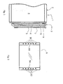
- FIG. 1 there is shown a sectional view of a portion of a household oven 1.
- the oven 1 comprises a frame 2 within which a muffle 4 is defined which opens outwards to be accessible to a user.
- the opening of the muffle 4 can be closed by a door 3, which in the present example has three glass panes: an inner glass pane 5 close to the muffle 4, an intermediate glass pane 6, and an outer glass pane 7.
- the glass panes 5, 6, 7 are normally enclosed by a frame made of plastic, metal or another material (not shown) which supports the glass panes 5, 6, 7 so as to keep them parallel to and spaced from one another.
- the frame includes seats into which the edges of the glass panes 5, 6 and 7 engage, thus staying locked in position.
- the intermediate glass pane 6 is positioned between the inner glass pane 5 and the outer glass pane 7, parallel thereto.
- a gasket is arranged at least between two contiguous glass panes (intermediate 6 and inner 5 or intermediate 6 and outer 7).
- the non-limiting example shown herein includes two gaskets: an inner one designated by reference numeral 8 and an outer one designated by reference numeral 9.
- the inner gasket 8 is interposed between the inner glass pane 5 and the intermediate glass pane 6, whereas the outer gasket 9 is interposed between the intermediate glass pane 6 and the outer glass pane 7.
- gasket 9 is used, to which reference will be made hereafter.
- the gasket 9 comprises two upright parts 9A and 9B which, when the door is vertical (i.e. closing the muffle 4), extend vertically as shown in Fig. 2 .
- the gasket 9 is interposed between the intermediate glass pane 6 and the outer one 7 and in contact with both, and prevents hot air from escaping from the door sides while leaving an upper aperture and a lower aperture for the air to flow from the muffle 4 to the outside.
- the gasket 9 thus defines the side walls of the chamber between the two glass panes 6 and 7 and, in accordance with the teachings of the present invention, houses the light sources 10 shown schematically in Fig. 2 , so as to provide the advantages discussed above.
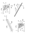
- the gasket 9 may have any cross section, whether shaped like a regular polygon or not.
- the gasket 9 has a substantially triangular cross-section with smoothed edges.
- the gasket is held in position by the frame and by both glass panes 6 and 7, the area in contact with the glass pane 6 (which is hotter) being smaller than the one in contact with the glass pane 7 (which is colder).
- the light sources 10 may be of any type, e.g. incandescent lamps or the like; however, in order to minimise their thermal contribution, the preferred solution uses LEDs (Light Emission Diodes), which produce very little heat.
- LEDs Light Emission Diodes
- Said light sources 10 are arranged in a housing 15 obtained within the gasket 9, so that they are completely surrounded by the material of the gasket 9, which acts as a thermal insulator, a mechanical insulator (it prevents the light sources from getting fouled by insulating them from the air circulating in the chamber between the two panes) and possibly also an electric insulator, as will be described hereafter.
- the housing 15 may be provided as a separate housing for each light source 10, as shown in Fig. 3 , or else as a single housing common to multiple (even all) light sources 10.
- the gasket 9 advantageously also performs the function of positioning, supporting and centering the light sources 10.
- the light sources are oriented in a manner such that the light is diffused evenly onto the different horizontal levels, e.g. corresponding to the various heights where dripping pans, trays or grills can be positioned.
- the light sources 10 typically have a body 10B and a luminous end 10A from which the light beam originates.
- the light source 10 can be secured into the gasket 9 in several ways.
- the gasket 9 can be moulded or directly extruded over the light sources 10, which therefore will remain buried or incorporated in the material of the gasket 9 itself, thus ensuring adequate sealing.
- the material of the gasket 9 is closely adherent to the light source 10, as shown in Fig. 4 .
- This solution may also be implemented by extruding the gasket directly over the light sources, and possibly also over the conductors.
- the light sources 10 are thus fixed along their whole perimeter by the material of the gasket 10 that incorporates them, and can be oriented by appropriately arranging the light sources 10 prior to the overmoulding process.
- each light source 10 is sealingly insulated from the outside environment because it is buried in the very material of the gasket 9.
- the gasket 90 is made up of two parts 90' and 90" which can be mutually coupled together, each comprising a portion of the walls that define the housing 15, as shown in Fig. 5 .
- the light sources 10 can be easily fixed by sizing the housing 15 in a manner such that the body 10B of each light source 10 fits into it by interference, thus staying locked in position.
- the correct orientation of the light sources 10 will in this case depend on the orientation of the housing 15.
- gasket 900' is made by extrusion; during the same extrusion step the single housing 15' is advantageously made as well, which houses all light sources. The latter are then placed into the housing 15', which is subsequently closed with a second gasket portion (not shown) laid over it as a cover, similarly to the portion 90" of Fig. 5 .
- the gasket 9 may be made of a suitable synthetic material, e.g. a platinic silicone rubber compound for food use having the following properties:
- This material is transparent, and therefore the gasket 9 will be wholly transparent as well: the light beam generated by each light source 10 will go through it, thus illuminating the muffle.
- Such a variant may be implemented by using two distinct materials for the gasket, one of which is transparent, or just one material coloured in some areas and transparent elsewhere.
- the portion 90', 900' of the gasket 90, 900 is opaque or anyway not transparent, while the portion 90", i.e. the one facing the muffle 4, is transparent.
- Figs. 4, 5 and 6 there is shown the power supply line of each light source.
- the power supply line comprises two electric conductors 11 and 12 buried in the material of the gasket 9.
- the two electric conductors 11 and 12 may be, for example, two simple electric wires, as in the example of Fig. 6 , or, alternatively, thin metal strips (e.g. made of aluminium or the like) or, especially when the sources 10 are LEDs, parts of a printed circuit adapted to supply power to said LEDs.
- the conductors 11 and 12 may establish a parallel connection between the light sources or, alternatively, the light sources 10 may be connected in series.
- the parallel connection has the drawback that two conductors are needed, but has the advantage that, should one light source fail, the other ones will continue to operate; vice versa, the series connection is less expensive (it may even employ just one conductor), but in the event of a faulty light source all other sources connected in series thereto will go off.
- the electric conductors 11 and 12 have no insulation, since this is provided by the very material of the gasket 9.
- single punctiform light sources 10 have been described so far, said light sources may of course be replaced with a single elongated light source, e.g. a neon lamp or the like.
- the light sources may be arranged along the gasket 8, in the same manner as described above.
- the gasket 9 is made as one piece with the gasket 8.
- the glass pane 6 performs the function of the above-described glass pane 5.
Landscapes
- Engineering & Computer Science (AREA)
- Chemical & Material Sciences (AREA)
- Combustion & Propulsion (AREA)
- Mechanical Engineering (AREA)
- General Engineering & Computer Science (AREA)
- Arrangement Of Elements, Cooling, Sealing, Or The Like Of Lighting Devices (AREA)
- Securing Of Glass Panes Or The Like (AREA)
- Electric Ovens (AREA)
- Constitution Of High-Frequency Heating (AREA)
- Circuit Arrangement For Electric Light Sources In General (AREA)
Abstract
Description
- The present invention relates to a lighting system for a household oven and to an oven equipped with such a lighting system.
- As known, household ovens are fitted with a lighting system adapted to illuminate their cooking chamber, or muffle, so that a user can see the food being cooked.
- Lighting systems typically comprise a light source placed inside the muffle, which can be turned on at will by the user or based on the operation of the oven.
- This solution however takes up room inside the muffle, thus reducing its usable volume, and also exposes the light source to the high temperatures which are normally found in that region of the oven.
- In order to solve this problem, a number of solutions have been conceived like the one described in patent application
EP1995522 by CANDY Spa. - In this solution, the light sources are mounted on the door that closes the cooking chamber, so as not to take up useful space in the muffle.
- More in particular, the door that closes the muffle is provided with a double glass, and the light sources are installed within the chamber formed between the two glass panes, supported by suitably shaped brackets, so that the light beam is oriented towards the centre of the muffle when the door is in the closed position.
- Although effective, this solution suffers from a number of drawbacks.
- In fact, though lower than in the muffle, the temperature in the chamber formed between the two glass panes of the oven door is still relatively high (approx. 200°C) and may damage the light sources or the electronic power circuits.
- In addition, in certain oven types, e.g. like the one shown in document
IT1237294 - In these oven types, therefore, it is not advisable to arrange the light sources as described in document
EP1995522 , since significant problems may arise. - The present invention aims at overcoming this drawback by providing a lighting system for a household oven which takes up no space in the muffle and cannot be damaged by the heat of the oven or fouled by the air coming from within the muffle.
- The object of the present invention is a lighting system for a household oven according to claim 1 appended hereto, as well as a household oven equipped with such a lighting system.
- The present invention is based upon the idea of arranging light sources within the gasket interposed between two glass panes of the oven door; to this end, the gasket is transparent at least in the area facing the light sources, so as to let through the light beam generated by the light sources and directed towards the muffle when the latter is closed by the door.
- This eliminates the above-mentioned drawbacks of the prior art, in that the gasket material completely surrounds the light sources, thereby protecting them from both the heat and the dirt carried by the air circulating in the chamber between the two glass panes.
- This solution may therefore be easily installed in any type of household oven, whether or not there is ventilation in the chamber between the glass panes.
- According to another advantageous feature, in addition to incorporating the light sources the gasket also incorporates that part of the power supply line which extends along the oven door, thus also protecting the latter from possible damage caused by heat and dirt.
- According to a further variant, the same gasket material may advantageously also be used for insulating the power supply line, with significant savings in terms of production and assembly times.
- Further advantageous features of the lighting system will be set out in the appended claims.
- These features as well as further advantages of the present invention will become apparent from the following description of an embodiment thereof as shown in the annexed drawings, which are supplied by way of non-limiting example, wherein:
-
Fig. 1 is a sectional view of a portion of a household oven equipped with a lighting system according to the present invention; -
Fig. 2 is a plan view of a gasket mounted on the door of the oven ofFig. 1 , within which the light sources are housed; -
Fig. 3 is a perspective view of a portion of the gasket ofFig. 2 ; -
Fig. 4 is a cross-sectional view of the gasket ofFig. 2 ; -
Fig. 5 is a cross-sectional view of a variant of the gasket ofFig. 4 ; -
Fig. 6 shows a variant of the gasket ofFig. 4 . - Referring now to
Fig. 1 , there is shown a sectional view of a portion of ahousehold oven 1. - The
oven 1 comprises aframe 2 within which amuffle 4 is defined which opens outwards to be accessible to a user. - The opening of the
muffle 4 can be closed by a door 3, which in the present example has three glass panes: aninner glass pane 5 close to themuffle 4, anintermediate glass pane 6, and anouter glass pane 7. - The
glass panes glass panes - In substance, the frame includes seats into which the edges of the
glass panes - The
intermediate glass pane 6 is positioned between theinner glass pane 5 and theouter glass pane 7, parallel thereto. - A gasket is arranged at least between two contiguous glass panes (intermediate 6 and inner 5 or intermediate 6 and outer 7).
- The non-limiting example shown herein includes two gaskets: an inner one designated by
reference numeral 8 and an outer one designated byreference numeral 9. - The
inner gasket 8 is interposed between theinner glass pane 5 and theintermediate glass pane 6, whereas theouter gasket 9 is interposed between theintermediate glass pane 6 and theouter glass pane 7. - In a preferred embodiment only the
gasket 9 is used, to which reference will be made hereafter. - The
gasket 9 comprises twoupright parts Fig. 2 . - The
gasket 9 is interposed between theintermediate glass pane 6 and the outer one 7 and in contact with both, and prevents hot air from escaping from the door sides while leaving an upper aperture and a lower aperture for the air to flow from themuffle 4 to the outside. - The
gasket 9 thus defines the side walls of the chamber between the twoglass panes light sources 10 shown schematically inFig. 2 , so as to provide the advantages discussed above. - In principle, the
gasket 9 may have any cross section, whether shaped like a regular polygon or not. - In the example shown in
Figs. 3 and 4 , thegasket 9 has a substantially triangular cross-section with smoothed edges. - Thus the gasket is held in position by the frame and by both
glass panes - This solution reduces the thermal exchange occurring by conduction between the
gasket 9 and theintermediate glass pane 6 compared to the thermal exchange occurring between theouter glass pane 7 and thegasket 9. - The
light sources 10 may be of any type, e.g. incandescent lamps or the like; however, in order to minimise their thermal contribution, the preferred solution uses LEDs (Light Emission Diodes), which produce very little heat. - Said
light sources 10 are arranged in ahousing 15 obtained within thegasket 9, so that they are completely surrounded by the material of thegasket 9, which acts as a thermal insulator, a mechanical insulator (it prevents the light sources from getting fouled by insulating them from the air circulating in the chamber between the two panes) and possibly also an electric insulator, as will be described hereafter. - The
housing 15 may be provided as a separate housing for eachlight source 10, as shown inFig. 3 , or else as a single housing common to multiple (even all)light sources 10. - This latter solution, shown in
Fig. 6 and described in detail below, is in principle preferable because it allows the gasket to be manufactured through a simple extrusion and cutting process. - The
gasket 9 advantageously also performs the function of positioning, supporting and centering thelight sources 10. - The latter, in fact, must be appropriately oriented in order to properly illuminate the chosen region of the muffle (when the door 3 is closing the muffle 4): preferably the light sources are oriented in a manner such that the light is diffused evenly onto the different horizontal levels, e.g. corresponding to the various heights where dripping pans, trays or grills can be positioned.
- The light sources 10 (whether LEDs or lamps of another kind) typically have a
body 10B and aluminous end 10A from which the light beam originates. - Since the material of the
gasket 9 is elastic, and thegasket 9 is normally manufactured by moulding or extrusion, thelight source 10 can be secured into thegasket 9 in several ways. - In a first case, the
gasket 9 can be moulded or directly extruded over thelight sources 10, which therefore will remain buried or incorporated in the material of thegasket 9 itself, thus ensuring adequate sealing. - In this case, the material of the
gasket 9 is closely adherent to thelight source 10, as shown inFig. 4 . - This solution may also be implemented by extruding the gasket directly over the light sources, and possibly also over the conductors.
- The
light sources 10 are thus fixed along their whole perimeter by the material of thegasket 10 that incorporates them, and can be oriented by appropriately arranging thelight sources 10 prior to the overmoulding process. - In this case a significant advantage is given by the fact that each
light source 10 is sealingly insulated from the outside environment because it is buried in the very material of thegasket 9. - In a second case, all the
single housings 15 needed for the light sources are obtained as thegasket 9 is being moulded, and thegasket 90 is made up of twoparts 90' and 90" which can be mutually coupled together, each comprising a portion of the walls that define thehousing 15, as shown inFig. 5 . - In this case, the
light sources 10 can be easily fixed by sizing thehousing 15 in a manner such that thebody 10B of eachlight source 10 fits into it by interference, thus staying locked in position. - The correct orientation of the
light sources 10 will in this case depend on the orientation of thehousing 15. - Here the assembly stage is longer than in the preceding case, but this solution has the advantage that the
single light sources 10 can be replaced individually, if damaged. - Yet another variant is the one shown in
Fig. 6 : in this case the gasket 900' is made by extrusion; during the same extrusion step the single housing 15' is advantageously made as well, which houses all light sources. The latter are then placed into the housing 15', which is subsequently closed with a second gasket portion (not shown) laid over it as a cover, similarly to theportion 90" ofFig. 5 . - As far as the
gasket 9 is concerned, it may be made of a suitable synthetic material, e.g. a platinic silicone rubber compound for food use having the following properties: - density: 1,180 kg/m3, measured according to the ASTM D 297 standard;
- hardness: 60° Shore A/3, measured according to the ASTM D2240 standard;
- tensile strength: 9 MPa, measured according to the ASTM D412 standard;
- ultimate elongation: 600%, measured according to the ASTM D412 standard;
- operating temperature: -50°C to +250°C.
- Such a material is available on the market under the commercial name DYNASIL ® 1460.
- This material is transparent, and therefore the
gasket 9 will be wholly transparent as well: the light beam generated by eachlight source 10 will go through it, thus illuminating the muffle. - As an alternative, instead of a wholly
transparent gasket 9 it is conceivable to use a transparent gasket only at the section that must be crossed by the light beams of the sources 10 (so that themuffle 4 can be illuminated when the door 3 is closed). - Such a variant may be implemented by using two distinct materials for the gasket, one of which is transparent, or just one material coloured in some areas and transparent elsewhere.
- For example, in the embodiment shown in
Fig. 5 or Fig. 6 it is conceivable that the portion 90', 900' of thegasket portion 90", i.e. the one facing themuffle 4, is transparent. - In this latter case there is the additional advantage that no areas are illuminated at the edge of the
glass pane 7 close to the light sources, thereby avoiding that possible reflections or refractions of the light beam might impair the vision through the various glass panes. - Referring now to
Figs. 4, 5 and 6 , there is shown the power supply line of each light source. - In this case, the power supply line comprises two
electric conductors gasket 9. - The two
electric conductors Fig. 6 , or, alternatively, thin metal strips (e.g. made of aluminium or the like) or, especially when thesources 10 are LEDs, parts of a printed circuit adapted to supply power to said LEDs. - The
conductors light sources 10 may be connected in series. - The parallel connection has the drawback that two conductors are needed, but has the advantage that, should one light source fail, the other ones will continue to operate; vice versa, the series connection is less expensive (it may even employ just one conductor), but in the event of a faulty light source all other sources connected in series thereto will go off.
- According to another variant, the
electric conductors gasket 9. - As concerns the orientation of the various
light sources 10 installed in the gasket, they can be oriented in parallel directions lying in horizontal planes (when the door is closed). - This will ensure a diffused illumination of the muffle at the various levels where shelves can be placed.
- Furthermore, although single punctiform
light sources 10 have been described so far, said light sources may of course be replaced with a single elongated light source, e.g. a neon lamp or the like. - According to another variant, the light sources may be arranged along the
gasket 8, in the same manner as described above. - In yet another variant, the
gasket 9 is made as one piece with thegasket 8. - In a different embodiment, instead of three
glass panes glass panes gasket 9 in between housing thelight sources 10 as previously described; in this case, of course, theglass pane 6 performs the function of the above-describedglass pane 5. - Based on the teachings provided herein, those skilled in the art may conceive further variants which will nevertheless still fall within the scope of the present invention.
Claims (10)
- A lighting system for a household oven (1), wherein the oven comprises a frame (2) that defines a muffle (4) having an opening that can be closed by a door (3), which door comprises at least a first and a second glass panes (6,7) between which a gasket (9,90,900) is arranged, the system comprising at least one light source (10) associated with said door (3),
characterised in that
said light source (10) is housed within said gasket (9,90,900), said gasket (9,90,900) being at least partly transparent, so as to let through a light beam generated by said light source (10) and directed towards said muffle (4) when the latter is closed by the door (3). - A system according to claim 1, wherein said gasket (9,90,900) is made of a synthetic material that completely surrounds said light source (10).
- A system according to claim 1 or 2, wherein said door (3) comprises three glass panes, i.e. an inner glass pane (5) facing the muffle, an outer glass pane (7) facing the outside environment of the oven (1) and an intermediate glass pane (6) arranged between the inner one (5) and the outer one (7), said three glass panes (5,6,7) being substantially parallel to and at a distance from one another, and wherein said gasket (9,90,900) is arranged between said intermediate glass pane (6) and said outer glass pane (7).
- A system according to one or more of the preceding claims, wherein said gasket (9,90,900) is wholly transparent.
- A system according to one or more of the preceding claims, wherein said light source (10) is housed within said gasket (90,900) in a housing (15,15') obtained when manufacturing said gasket (90,900).
- A system according to the preceding claim, wherein said gasket (90,900) comprises a first portion (90',900') and a second portion (90") which can be mutually coupled together, each comprising a part of the housing (15,15').
- A system according to one or more of claims 1 to 4, wherein said gasket (9) is moulded over said light sources (10).
- A system according to one or more of the preceding claims, comprising a plurality of light sources (10), wherein said light sources (10) are LEDs, Light Emission Diodes.
- A system according to one or more of the preceding claims, wherein said gasket (9,90) is made of a platinic silicone rubber compound for food use.
- A household oven (1) comprising a lighting system according to one or more of claims 1 to 9.
Priority Applications (2)
| Application Number | Priority Date | Filing Date | Title |
|---|---|---|---|
| SI201030224T SI2336644T1 (en) | 2009-12-17 | 2010-12-14 | Household oven comprising a door with a lighting system |
| PL10195019T PL2336644T3 (en) | 2009-12-17 | 2010-12-14 | Household oven comprising a door with a lighting system |
Applications Claiming Priority (1)
| Application Number | Priority Date | Filing Date | Title |
|---|---|---|---|
| IT000999A ITTO20090999A1 (en) | 2009-12-17 | 2009-12-17 | LIGHTING SYSTEM FOR A DOMESTIC OVEN AND TO A OVEN PROVIDED WITH SUCH A LIGHTING SYSTEM |
Publications (2)
| Publication Number | Publication Date |
|---|---|
| EP2336644A1 true EP2336644A1 (en) | 2011-06-22 |
| EP2336644B1 EP2336644B1 (en) | 2013-03-06 |
Family
ID=42646267
Family Applications (1)
| Application Number | Title | Priority Date | Filing Date |
|---|---|---|---|
| EP10195019A Active EP2336644B1 (en) | 2009-12-17 | 2010-12-14 | Household oven comprising a door with a lighting system |
Country Status (5)
| Country | Link |
|---|---|
| EP (1) | EP2336644B1 (en) |
| ES (1) | ES2411460T3 (en) |
| IT (1) | ITTO20090999A1 (en) |
| PL (1) | PL2336644T3 (en) |
| SI (1) | SI2336644T1 (en) |
Cited By (7)
| Publication number | Priority date | Publication date | Assignee | Title |
|---|---|---|---|---|
| EP2551601A3 (en) * | 2011-07-29 | 2013-04-03 | BSH Bosch und Siemens Hausgeräte GmbH | Domestic appliance door with a lighting device |
| EP2592354A1 (en) * | 2011-11-14 | 2013-05-15 | BSH Bosch und Siemens Hausgeräte GmbH | Cooking device with a door that can be retracted into the housing of the cooking device |
| EP2653786A1 (en) * | 2012-04-20 | 2013-10-23 | Candy S.p.A. | Oven with lighting system |
| DE202015103727U1 (en) * | 2015-07-16 | 2016-10-18 | Rational Aktiengesellschaft | Cooking appliance with light control |
| DE202015103729U1 (en) * | 2015-07-16 | 2016-10-18 | Rational Aktiengesellschaft | Cooking appliance with light control |
| WO2017207245A1 (en) * | 2016-06-02 | 2017-12-07 | BSH Hausgeräte GmbH | Household appliance for preparing food in an outer part displaying optical information |
| EP4206544A1 (en) | 2021-12-29 | 2023-07-05 | SMEG S.p.A. | Oven muffle provided with a lighting device for illuminating the cooking chamber |
Families Citing this family (2)
| Publication number | Priority date | Publication date | Assignee | Title |
|---|---|---|---|---|
| US11287140B2 (en) | 2019-01-04 | 2022-03-29 | Whirlpool Corporation | Cooking appliance with an imaging device |
| US11022322B2 (en) | 2019-01-04 | 2021-06-01 | Whirlpool Corporation | Cooking appliance with an imaging device |
Citations (2)
| Publication number | Priority date | Publication date | Assignee | Title |
|---|---|---|---|---|
| IT1237294B (en) | 1989-11-27 | 1993-05-27 | Merloni Elettrodomestici Spa | OVEN DOOR COOLING SYSTEM |
| EP1995522A1 (en) | 2007-05-25 | 2008-11-26 | CANDY S.p.A. | Oven |
-
2009
- 2009-12-17 IT IT000999A patent/ITTO20090999A1/en unknown
-
2010
- 2010-12-14 EP EP10195019A patent/EP2336644B1/en active Active
- 2010-12-14 PL PL10195019T patent/PL2336644T3/en unknown
- 2010-12-14 ES ES10195019T patent/ES2411460T3/en active Active
- 2010-12-14 SI SI201030224T patent/SI2336644T1/en unknown
Patent Citations (2)
| Publication number | Priority date | Publication date | Assignee | Title |
|---|---|---|---|---|
| IT1237294B (en) | 1989-11-27 | 1993-05-27 | Merloni Elettrodomestici Spa | OVEN DOOR COOLING SYSTEM |
| EP1995522A1 (en) | 2007-05-25 | 2008-11-26 | CANDY S.p.A. | Oven |
Cited By (7)
| Publication number | Priority date | Publication date | Assignee | Title |
|---|---|---|---|---|
| EP2551601A3 (en) * | 2011-07-29 | 2013-04-03 | BSH Bosch und Siemens Hausgeräte GmbH | Domestic appliance door with a lighting device |
| EP2592354A1 (en) * | 2011-11-14 | 2013-05-15 | BSH Bosch und Siemens Hausgeräte GmbH | Cooking device with a door that can be retracted into the housing of the cooking device |
| EP2653786A1 (en) * | 2012-04-20 | 2013-10-23 | Candy S.p.A. | Oven with lighting system |
| DE202015103727U1 (en) * | 2015-07-16 | 2016-10-18 | Rational Aktiengesellschaft | Cooking appliance with light control |
| DE202015103729U1 (en) * | 2015-07-16 | 2016-10-18 | Rational Aktiengesellschaft | Cooking appliance with light control |
| WO2017207245A1 (en) * | 2016-06-02 | 2017-12-07 | BSH Hausgeräte GmbH | Household appliance for preparing food in an outer part displaying optical information |
| EP4206544A1 (en) | 2021-12-29 | 2023-07-05 | SMEG S.p.A. | Oven muffle provided with a lighting device for illuminating the cooking chamber |
Also Published As
| Publication number | Publication date |
|---|---|
| ITTO20090999A1 (en) | 2011-06-18 |
| SI2336644T1 (en) | 2013-07-31 |
| EP2336644B1 (en) | 2013-03-06 |
| ES2411460T3 (en) | 2013-07-05 |
| PL2336644T3 (en) | 2013-08-30 |
Similar Documents
| Publication | Publication Date | Title |
|---|---|---|
| EP2336644B1 (en) | Household oven comprising a door with a lighting system | |
| ES2700460T3 (en) | Cooking appliance | |
| US8405003B2 (en) | Oven having diffuse light pipe assembly | |
| US20090071463A1 (en) | Lighting Device for Ovens, and Oven | |
| US9528709B2 (en) | Lighting system for an oven appliance | |
| KR101005703B1 (en) | Fluorescent lighting fixture for cleanroom | |
| EP2257744B1 (en) | Household cooking oven | |
| AU2007278519B2 (en) | Household broiling and/or baking oven | |
| AU2010297629A1 (en) | An oven with at least one illuminated oven cavity | |
| US9482436B1 (en) | Lighting system for an oven appliance | |
| US9182112B2 (en) | Sheet lighting in an appliance | |
| US10655863B1 (en) | Luminaire for domestic electric appliance, such as a domestic oven | |
| JP6318369B2 (en) | Cooker | |
| JP2008089279A (en) | Refrigerator | |
| US20120133262A1 (en) | Household appliance including glass interior walls | |
| JP5340985B2 (en) | Thermostatic device | |
| GB2486845A (en) | Household cooking appliance with light to illuminate different rack levels | |
| EP3040625B1 (en) | A cooking device with hinged cover having an illuminating member | |
| JP6913593B2 (en) | Environment forming device and window structure | |
| JP2012154578A (en) | Refrigerator | |
| CN217161829U (en) | Cooking appliance and inner container assembly thereof | |
| JP2011086575A (en) | Lighting system for exhaust hood | |
| CN219069980U (en) | Door body assembly and cooking utensil | |
| JP2015173007A (en) | Lighting device and lighting unit | |
| EP4206544A1 (en) | Oven muffle provided with a lighting device for illuminating the cooking chamber |
Legal Events
| Date | Code | Title | Description |
|---|---|---|---|
| PUAI | Public reference made under article 153(3) epc to a published international application that has entered the european phase |
Free format text: ORIGINAL CODE: 0009012 |
|
| AK | Designated contracting states |
Kind code of ref document: A1 Designated state(s): AL AT BE BG CH CY CZ DE DK EE ES FI FR GB GR HR HU IE IS IT LI LT LU LV MC MK MT NL NO PL PT RO RS SE SI SK SM TR |
|
| AX | Request for extension of the european patent |
Extension state: BA ME |
|
| 17P | Request for examination filed |
Effective date: 20111123 |
|
| GRAP | Despatch of communication of intention to grant a patent |
Free format text: ORIGINAL CODE: EPIDOSNIGR1 |
|
| GRAS | Grant fee paid |
Free format text: ORIGINAL CODE: EPIDOSNIGR3 |
|
| GRAA | (expected) grant |
Free format text: ORIGINAL CODE: 0009210 |
|
| AK | Designated contracting states |
Kind code of ref document: B1 Designated state(s): AL AT BE BG CH CY CZ DE DK EE ES FI FR GB GR HR HU IE IS IT LI LT LU LV MC MK MT NL NO PL PT RO RS SE SI SK SM TR |
|
| REG | Reference to a national code |
Ref country code: GB Ref legal event code: FG4D |
|
| REG | Reference to a national code |
Ref country code: CH Ref legal event code: EP Ref country code: AT Ref legal event code: REF Ref document number: 599857 Country of ref document: AT Kind code of ref document: T Effective date: 20130315 |
|
| REG | Reference to a national code |
Ref country code: IE Ref legal event code: FG4D |
|
| REG | Reference to a national code |
Ref country code: DE Ref legal event code: R096 Ref document number: 602010005242 Country of ref document: DE Effective date: 20130502 |
|
| REG | Reference to a national code |
Ref country code: ES Ref legal event code: FG2A Ref document number: 2411460 Country of ref document: ES Kind code of ref document: T3 Effective date: 20130705 |
|
| REG | Reference to a national code |
Ref country code: AT Ref legal event code: MK05 Ref document number: 599857 Country of ref document: AT Kind code of ref document: T Effective date: 20130306 |
|
| PG25 | Lapsed in a contracting state [announced via postgrant information from national office to epo] |
Ref country code: SE Free format text: LAPSE BECAUSE OF FAILURE TO SUBMIT A TRANSLATION OF THE DESCRIPTION OR TO PAY THE FEE WITHIN THE PRESCRIBED TIME-LIMIT Effective date: 20130306 Ref country code: NO Free format text: LAPSE BECAUSE OF FAILURE TO SUBMIT A TRANSLATION OF THE DESCRIPTION OR TO PAY THE FEE WITHIN THE PRESCRIBED TIME-LIMIT Effective date: 20130606 Ref country code: BG Free format text: LAPSE BECAUSE OF FAILURE TO SUBMIT A TRANSLATION OF THE DESCRIPTION OR TO PAY THE FEE WITHIN THE PRESCRIBED TIME-LIMIT Effective date: 20130606 Ref country code: AT Free format text: LAPSE BECAUSE OF FAILURE TO SUBMIT A TRANSLATION OF THE DESCRIPTION OR TO PAY THE FEE WITHIN THE PRESCRIBED TIME-LIMIT Effective date: 20130306 Ref country code: LT Free format text: LAPSE BECAUSE OF FAILURE TO SUBMIT A TRANSLATION OF THE DESCRIPTION OR TO PAY THE FEE WITHIN THE PRESCRIBED TIME-LIMIT Effective date: 20130306 |
|
| REG | Reference to a national code |
Ref country code: NL Ref legal event code: VDEP Effective date: 20130306 |
|
| REG | Reference to a national code |
Ref country code: LT Ref legal event code: MG4D |
|
| PG25 | Lapsed in a contracting state [announced via postgrant information from national office to epo] |
Ref country code: GR Free format text: LAPSE BECAUSE OF FAILURE TO SUBMIT A TRANSLATION OF THE DESCRIPTION OR TO PAY THE FEE WITHIN THE PRESCRIBED TIME-LIMIT Effective date: 20130607 Ref country code: LV Free format text: LAPSE BECAUSE OF FAILURE TO SUBMIT A TRANSLATION OF THE DESCRIPTION OR TO PAY THE FEE WITHIN THE PRESCRIBED TIME-LIMIT Effective date: 20130306 Ref country code: FI Free format text: LAPSE BECAUSE OF FAILURE TO SUBMIT A TRANSLATION OF THE DESCRIPTION OR TO PAY THE FEE WITHIN THE PRESCRIBED TIME-LIMIT Effective date: 20130306 |
|
| REG | Reference to a national code |
Ref country code: PL Ref legal event code: T3 |
|
| PG25 | Lapsed in a contracting state [announced via postgrant information from national office to epo] |
Ref country code: RS Free format text: LAPSE BECAUSE OF FAILURE TO SUBMIT A TRANSLATION OF THE DESCRIPTION OR TO PAY THE FEE WITHIN THE PRESCRIBED TIME-LIMIT Effective date: 20130306 Ref country code: HR Free format text: LAPSE BECAUSE OF FAILURE TO SUBMIT A TRANSLATION OF THE DESCRIPTION OR TO PAY THE FEE WITHIN THE PRESCRIBED TIME-LIMIT Effective date: 20130306 Ref country code: BE Free format text: LAPSE BECAUSE OF FAILURE TO SUBMIT A TRANSLATION OF THE DESCRIPTION OR TO PAY THE FEE WITHIN THE PRESCRIBED TIME-LIMIT Effective date: 20130306 |
|
| PG25 | Lapsed in a contracting state [announced via postgrant information from national office to epo] |
Ref country code: EE Free format text: LAPSE BECAUSE OF FAILURE TO SUBMIT A TRANSLATION OF THE DESCRIPTION OR TO PAY THE FEE WITHIN THE PRESCRIBED TIME-LIMIT Effective date: 20130306 Ref country code: PT Free format text: LAPSE BECAUSE OF FAILURE TO SUBMIT A TRANSLATION OF THE DESCRIPTION OR TO PAY THE FEE WITHIN THE PRESCRIBED TIME-LIMIT Effective date: 20130708 Ref country code: NL Free format text: LAPSE BECAUSE OF FAILURE TO SUBMIT A TRANSLATION OF THE DESCRIPTION OR TO PAY THE FEE WITHIN THE PRESCRIBED TIME-LIMIT Effective date: 20130306 Ref country code: RO Free format text: LAPSE BECAUSE OF FAILURE TO SUBMIT A TRANSLATION OF THE DESCRIPTION OR TO PAY THE FEE WITHIN THE PRESCRIBED TIME-LIMIT Effective date: 20130306 Ref country code: IS Free format text: LAPSE BECAUSE OF FAILURE TO SUBMIT A TRANSLATION OF THE DESCRIPTION OR TO PAY THE FEE WITHIN THE PRESCRIBED TIME-LIMIT Effective date: 20130706 Ref country code: SK Free format text: LAPSE BECAUSE OF FAILURE TO SUBMIT A TRANSLATION OF THE DESCRIPTION OR TO PAY THE FEE WITHIN THE PRESCRIBED TIME-LIMIT Effective date: 20130306 Ref country code: CZ Free format text: LAPSE BECAUSE OF FAILURE TO SUBMIT A TRANSLATION OF THE DESCRIPTION OR TO PAY THE FEE WITHIN THE PRESCRIBED TIME-LIMIT Effective date: 20130306 |
|
| PLBE | No opposition filed within time limit |
Free format text: ORIGINAL CODE: 0009261 |
|
| STAA | Information on the status of an ep patent application or granted ep patent |
Free format text: STATUS: NO OPPOSITION FILED WITHIN TIME LIMIT |
|
| PG25 | Lapsed in a contracting state [announced via postgrant information from national office to epo] |
Ref country code: DK Free format text: LAPSE BECAUSE OF FAILURE TO SUBMIT A TRANSLATION OF THE DESCRIPTION OR TO PAY THE FEE WITHIN THE PRESCRIBED TIME-LIMIT Effective date: 20130306 |
|
| 26N | No opposition filed |
Effective date: 20131209 |
|
| REG | Reference to a national code |
Ref country code: DE Ref legal event code: R097 Ref document number: 602010005242 Country of ref document: DE Effective date: 20131209 |
|
| PG25 | Lapsed in a contracting state [announced via postgrant information from national office to epo] |
Ref country code: MC Free format text: LAPSE BECAUSE OF FAILURE TO SUBMIT A TRANSLATION OF THE DESCRIPTION OR TO PAY THE FEE WITHIN THE PRESCRIBED TIME-LIMIT Effective date: 20130306 Ref country code: LU Free format text: LAPSE BECAUSE OF FAILURE TO SUBMIT A TRANSLATION OF THE DESCRIPTION OR TO PAY THE FEE WITHIN THE PRESCRIBED TIME-LIMIT Effective date: 20131214 |
|
| REG | Reference to a national code |
Ref country code: IE Ref legal event code: MM4A |
|
| PG25 | Lapsed in a contracting state [announced via postgrant information from national office to epo] |
Ref country code: IE Free format text: LAPSE BECAUSE OF NON-PAYMENT OF DUE FEES Effective date: 20131214 |
|
| PG25 | Lapsed in a contracting state [announced via postgrant information from national office to epo] |
Ref country code: SM Free format text: LAPSE BECAUSE OF FAILURE TO SUBMIT A TRANSLATION OF THE DESCRIPTION OR TO PAY THE FEE WITHIN THE PRESCRIBED TIME-LIMIT Effective date: 20130306 |
|
| PG25 | Lapsed in a contracting state [announced via postgrant information from national office to epo] |
Ref country code: CY Free format text: LAPSE BECAUSE OF FAILURE TO SUBMIT A TRANSLATION OF THE DESCRIPTION OR TO PAY THE FEE WITHIN THE PRESCRIBED TIME-LIMIT Effective date: 20130306 |
|
| PG25 | Lapsed in a contracting state [announced via postgrant information from national office to epo] |
Ref country code: HU Free format text: LAPSE BECAUSE OF FAILURE TO SUBMIT A TRANSLATION OF THE DESCRIPTION OR TO PAY THE FEE WITHIN THE PRESCRIBED TIME-LIMIT; INVALID AB INITIO Effective date: 20101214 Ref country code: MK Free format text: LAPSE BECAUSE OF FAILURE TO SUBMIT A TRANSLATION OF THE DESCRIPTION OR TO PAY THE FEE WITHIN THE PRESCRIBED TIME-LIMIT Effective date: 20130306 |
|
| REG | Reference to a national code |
Ref country code: CH Ref legal event code: PL |
|
| PG25 | Lapsed in a contracting state [announced via postgrant information from national office to epo] |
Ref country code: MT Free format text: LAPSE BECAUSE OF FAILURE TO SUBMIT A TRANSLATION OF THE DESCRIPTION OR TO PAY THE FEE WITHIN THE PRESCRIBED TIME-LIMIT Effective date: 20130306 |
|
| PG25 | Lapsed in a contracting state [announced via postgrant information from national office to epo] |
Ref country code: CH Free format text: LAPSE BECAUSE OF NON-PAYMENT OF DUE FEES Effective date: 20141231 Ref country code: LI Free format text: LAPSE BECAUSE OF NON-PAYMENT OF DUE FEES Effective date: 20141231 |
|
| REG | Reference to a national code |
Ref country code: FR Ref legal event code: PLFP Year of fee payment: 6 |
|
| REG | Reference to a national code |
Ref country code: FR Ref legal event code: PLFP Year of fee payment: 7 |
|
| PGFP | Annual fee paid to national office [announced via postgrant information from national office to epo] |
Ref country code: ES Payment date: 20161111 Year of fee payment: 7 Ref country code: SI Payment date: 20161108 Year of fee payment: 7 |
|
| PGFP | Annual fee paid to national office [announced via postgrant information from national office to epo] |
Ref country code: TR Payment date: 20161101 Year of fee payment: 7 |
|
| REG | Reference to a national code |
Ref country code: FR Ref legal event code: PLFP Year of fee payment: 8 |
|
| REG | Reference to a national code |
Ref country code: SI Ref legal event code: KO00 Effective date: 20180806 |
|
| PG25 | Lapsed in a contracting state [announced via postgrant information from national office to epo] |
Ref country code: AL Free format text: LAPSE BECAUSE OF FAILURE TO SUBMIT A TRANSLATION OF THE DESCRIPTION OR TO PAY THE FEE WITHIN THE PRESCRIBED TIME-LIMIT Effective date: 20130306 |
|
| PG25 | Lapsed in a contracting state [announced via postgrant information from national office to epo] |
Ref country code: SI Free format text: LAPSE BECAUSE OF NON-PAYMENT OF DUE FEES Effective date: 20171215 |
|
| REG | Reference to a national code |
Ref country code: ES Ref legal event code: FD2A Effective date: 20190703 |
|
| PG25 | Lapsed in a contracting state [announced via postgrant information from national office to epo] |
Ref country code: ES Free format text: LAPSE BECAUSE OF NON-PAYMENT OF DUE FEES Effective date: 20171215 |
|
| PGFP | Annual fee paid to national office [announced via postgrant information from national office to epo] |
Ref country code: DE Payment date: 20211019 Year of fee payment: 12 Ref country code: GB Payment date: 20211021 Year of fee payment: 12 Ref country code: FR Payment date: 20211109 Year of fee payment: 12 |
|
| PGFP | Annual fee paid to national office [announced via postgrant information from national office to epo] |
Ref country code: IT Payment date: 20211110 Year of fee payment: 12 |
|
| PGFP | Annual fee paid to national office [announced via postgrant information from national office to epo] |
Ref country code: PL Payment date: 20211005 Year of fee payment: 12 |
|
| PG25 | Lapsed in a contracting state [announced via postgrant information from national office to epo] |
Ref country code: TR Free format text: LAPSE BECAUSE OF NON-PAYMENT OF DUE FEES Effective date: 20171214 |
|
| REG | Reference to a national code |
Ref country code: DE Ref legal event code: R119 Ref document number: 602010005242 Country of ref document: DE |
|
| GBPC | Gb: european patent ceased through non-payment of renewal fee |
Effective date: 20221214 |
|
| PG25 | Lapsed in a contracting state [announced via postgrant information from national office to epo] |
Ref country code: GB Free format text: LAPSE BECAUSE OF NON-PAYMENT OF DUE FEES Effective date: 20221214 Ref country code: DE Free format text: LAPSE BECAUSE OF NON-PAYMENT OF DUE FEES Effective date: 20230701 |
|
| PG25 | Lapsed in a contracting state [announced via postgrant information from national office to epo] |
Ref country code: FR Free format text: LAPSE BECAUSE OF NON-PAYMENT OF DUE FEES Effective date: 20221231 |
|
| PG25 | Lapsed in a contracting state [announced via postgrant information from national office to epo] |
Ref country code: IT Free format text: LAPSE BECAUSE OF NON-PAYMENT OF DUE FEES Effective date: 20221214 |