EP2336559A1 - Unité de transfert de courant d'éclairage pour éolienne - Google Patents
Unité de transfert de courant d'éclairage pour éolienne Download PDFInfo
- Publication number
- EP2336559A1 EP2336559A1 EP09179257A EP09179257A EP2336559A1 EP 2336559 A1 EP2336559 A1 EP 2336559A1 EP 09179257 A EP09179257 A EP 09179257A EP 09179257 A EP09179257 A EP 09179257A EP 2336559 A1 EP2336559 A1 EP 2336559A1
- Authority
- EP
- European Patent Office
- Prior art keywords
- contact
- lightning current
- transfer unit
- spring
- current transfer
- Prior art date
- Legal status (The legal status is an assumption and is not a legal conclusion. Google has not performed a legal analysis and makes no representation as to the accuracy of the status listed.)
- Withdrawn
Links
Images


Classifications
-
- F—MECHANICAL ENGINEERING; LIGHTING; HEATING; WEAPONS; BLASTING
- F03—MACHINES OR ENGINES FOR LIQUIDS; WIND, SPRING, OR WEIGHT MOTORS; PRODUCING MECHANICAL POWER OR A REACTIVE PROPULSIVE THRUST, NOT OTHERWISE PROVIDED FOR
- F03D—WIND MOTORS
- F03D80/00—Details, components or accessories not provided for in groups F03D1/00 - F03D17/00
- F03D80/30—Lightning protection
-
- Y—GENERAL TAGGING OF NEW TECHNOLOGICAL DEVELOPMENTS; GENERAL TAGGING OF CROSS-SECTIONAL TECHNOLOGIES SPANNING OVER SEVERAL SECTIONS OF THE IPC; TECHNICAL SUBJECTS COVERED BY FORMER USPC CROSS-REFERENCE ART COLLECTIONS [XRACs] AND DIGESTS
- Y02—TECHNOLOGIES OR APPLICATIONS FOR MITIGATION OR ADAPTATION AGAINST CLIMATE CHANGE
- Y02E—REDUCTION OF GREENHOUSE GAS [GHG] EMISSIONS, RELATED TO ENERGY GENERATION, TRANSMISSION OR DISTRIBUTION
- Y02E10/00—Energy generation through renewable energy sources
- Y02E10/70—Wind energy
- Y02E10/72—Wind turbines with rotation axis in wind direction
Definitions
- the present invention relates to lightning current conduction in wind turbines and, for example, to a lightning current transfer unit for a wind turbine, and a wind turbine comprising one or more lightning current transfer units.
- a lightning current transfer unit for a wind turbine is known, for example, from WO 2005/050008 . It enables lightning current to be transferred from a rotor blade of the wind turbine to the wind turbine's nacelle by means of two contact sliders each contacting a complementary contact rail.
- the contact sliders have slide pieces mounted on a base support by means of elastically deformable flat strips, which bias the contact pieces towards the complementary contact rails (see e.g. Figs. 3a, 3b and 4 of WO 2005/050008 ).
- EP 1154537 A2 Another type of lightning transfer unit has been proposed in EP 1154537 A2 . It is arranged to enable lightning current to be transferred from a wind turbine's nacelle to the tower by means of a contact slider with a slide piece biased towards a complementary ring by means of a spring. The spring is directly mounted on the slide piece so that the direction in which the spring produces force is the direction in which the slide piece slider is biased towards the ring (see Fig. 8 of EP 1154537 A2 ).
- spark gaps to transfer lightning current between parts rotatable relatively to each other are provided.
- Contact sliders are connected in parallel with the spark gaps in order to enable charges to be discharged continuously.
- Each contact slider has a slide piece biased towards a complementary contact rail by means of a spring.
- the spring is directly mounted on the slide piece and produces force in the same direction in which the slide piece is biased towards the contact rail (see Fig. 2-4 of EP 01577551 A2 ).
- a lightning current transfer unit for a wind turbine comprises at least a first part and a second part rotatable relative to each other.
- the lightning current transfer unit comprises at least one contact slider arranged to contact a complementary contact rail, which is movable relative to the contact slider, to transfer lightning current from the first part to the second part.
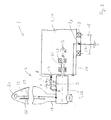
- the contact slider comprises: a slide piece, at least one pivoted lever, and at least one spring.
- the slide piece is mounted on the pivoted lever.
- the slide piece is biased towards the complementary contact rail in a contact-force direction.
- the spring applies an elastic spring force to the pivoted lever in a spring-force direction.
- the spring-force direction is at an angle to the contact-force direction.
- the pivoted lever diverts the spring force from the spring-force direction to the contact-force direction.
- a wind turbine comprising at least one lightning current transfer unit.
- Wind turbines are commonly equipped with a lightning conductor system.
- each rotor blade of a wind turbine has a lightning receptor near its tip, and sometimes further receptors along the blade.
- the lightning receptor, or receptors can be connected with a lightning conductor along the rotor blade.
- the lightning current path continues through the nacelle and down the tower of the wind turbine to the earth.
- the lightning current also has to pass between parts rotatable relative to each other, for example from the rotor blade to the rotor hub, from the rotor hub to the nacelle (or directly from the rotor blade to the nacelle), and from the nacelle to the tower.
- a lightning current transfer unit which transfers lightning current from a first part to a second part rotatable relative to each other.
- a galvanic connection there is no permanent discharge-current path which would allow charges from static charging to be permanently discharged.
- the embodiments therefore pertain to a lightning current transfer unit that provides a galvanic connection between the two parts rotatable relative to each other.
- a spark gap with movable spark-gap electrodes may be connected in parallel to the galvanic connection, as in EP 01577551 A2 mentioned at the outset; in other embodiments the galvanic connection is the only connection between the two parts rotatable relative to each other provided by the lightning current transfer unit, i.e. there is no parallel spark gap with moveable spark-gap electrodes.
- Galvanic connection is generally provided by contact elements mechanically contacting each other while being movable relative to each other.
- Galvanic connection can, in principle, also be provided by roller contacts, as, for example, in EP 1568883 A2 .
- contact arrangements based on roller contacts provide a reliable galvanic connection if the voltage across the contact is small, because oxide layers and dirt are not always removed by a roller contact.
- the embodiments of a lightning current transfer unit described in this description are based on sliding-contact arrangements to ensure that a permanent galvanic connection is provided to enable charges from static charging to be reliably discharged.
- a sliding-contact arrangement comprises a contact slider and a complementary contact rail movable relative to the contact slider.
- the contact slider has a slide piece biased towards the contact rail and in mechanical contact with it.
- the elastic biasing of the slide piece towards the contact rail compensates for variations in the distance between the lightning current transfer unit and the contact rail that may occur upon relative rotation, so that mechanical and electrical contact between the contact slider and contact rail is maintained.
- the embodiments of the lightning current transfer unit have one or more contact sliders.
- the complementary contact rail is mechanically contacted by the slide piece upon relative rotation of the contact slider and the complementary contact rail, the contact rail does not form part of the lightning current transfer unit itself.
- the contact rail is, for example, a full ring or ring sector attached e.g. to the root of a rotor blade, the rotor hub, the nacelle, or the head of the tower. If the relative rotation does not extend to full revolutions (such as the rotation between the rotor hub and the nacelle), but is limited to an only partial revolution (less than 360°, such as the rotation between a pitchable rotor blade and the rotor hub), the complementary rail may be a ring sector (also called "belt"). It extends over a limited angular range, at least corresponding to the angular range of the relative rotation concerned.
- the slide piece is a rigid member, while in other embodiments it may be a device having some elasticity to mechanically contact the contact rail on its own, e.g. a sort of electrically conductive brush.
- the lightning current transfer unit comprises a pivoted lever and a spring for each slide piece.
- the slide piece is mounted on its pivoted lever.
- the spring, or each of the springs is a compressed helical spring (or coil spring).
- Each slide piece is biased towards the complementary contact rail in a contact-force direction by its associated spring.
- the spring applies its elastic spring force to the pivoted lever associated with it in a spring-force direction.
- the spring-force direction is at an angle to the contact-force direction. In other words, the pivoted lever diverts the spring force from the spring-force direction to the contact-force direction.
- This diversion of the spring-force enables the lightning current transfer unit to be designed in a compact manner, in particular if it accommodates not only one, but two or more contact sliders.
- the lengths of the lever arms at which the spring force is applied and on which the slide piece is mounted are different, so that the spring force is transformed: the contact force is reduced relative to the spring force if the spring-lever arm is shorter than the slide-piece-lever arm, and it is increased relative to the spring force if the spring-lever arm is longer than the slide-piece-lever arm.
- the angle between the spring-force direction and the contact-force direction is, in some embodiments between 30° and 150°, in other embodiments between 45° and 135°.
- the spring-force direction is transverse to the contact-force direction.
- the pivoted lever diverts the spring force by about 90°.
- Such an arrangement is particularly useful in embodiments of the lightning current transfer unit with two contact sliders arranged back-to-back, because it enables the two slide pieces to be arranged at a distance from each other smaller than the length of one spring in its operational state in the spring-force direction. For example, in embodiments with a helical spring, or springs, this is the length of the spring in its axial direction when it is compressed such that the slide piece contacts its contact rail.
- the surfaces of the two slide pieces lie in parallel planes, and the two (e.g. helical) springs are arranged with their axes parallel to each other and the slide piece surfaces.
- the slide piece is pivotally mounted on the pivoted lever. This enables the slide piece to adapt its orientation parallel to the complementary contact rail when the lever is swivelled. Parallelism is then automatically maintained by the elastic pressure on the slide piece towards the contact rail.
- This pivotal mounting of the slide piece is not mandatory, as in other embodiments the angular change of the slide piece's orientation due to lever swivel is negligible, or the slide piece may have a slightly crowned surface.
- the slide piece comprises an electrically conductive contact pad and a wear pad which surrounds the conductive contact pad at least partially. Both the conductive contact pad and the wear pad form a common plane surface in mechanical contact with the contact rail.
- the wear pad enlarges the mechanically sliding surface of the slide piece beyond the electrically effective slide-piece surface, and allows a material to be chosen (e.g. a high-strength plastic) which exhibits less wear than the conductive contact pad. This enables the contact slider to be operated without some of the restrictions associated with the conductive contact pad.
- a relatively high contact force can be chosen to prevent slider lift-off while keeping wear of the conductive contact pad low, due to pressure reduction as a consequence of the enlargement of the slide piece's surface by the wear pad, and due to the wear pad's superior wear characteristic.
- the lightning current transfer unit comprises a base support made of insulating material, e.g. insulating plastic.
- the isolating base support supports the pivoted lever with the slide piece.
- the base support is a common support of both the pivoted levers and slide pieces. The base support may be made as an integral part.
- the pivoted lever is pivotally mounted around a swivel axis on the base support either directly, or indirectly with interposition of a member fixed to the base support.
- the spring, or each spring is accommodated in a spring cylinder.
- the cylinder, or cylinders is/are mounted on the base support, and the pivoted lever is pivotally mounted on its associated spring cylinder.
- the spring cylinder may thus form the member interposed between the base support and the pivoted lever on which the latter is mounted.
- the member/spring cylinder and/or the pivoted lever are also made of insulating material, e.g. insulating plastic.
- the base support is in the general form of an elevated platform with side walls and is a hollow body defined by the platform and the side walls.
- a spring-cylinder mounting is provided for the, or each, spring cylinder.
- a spring-cylinder mounting may, e.g., be a bracket with a semi-cylindrical shape.
- the two slide pieces are positioned at different levels above the basis of the base support, depending on the relative position of the two associated contact rails. For example, only one of the spring-cylinder mountings is mounted on the elevated platform, while the other is located at a lower level. In other embodiments, however, the two slide pieces are at the same height; both spring-cylinder mountings are on the elevated platform.
- the lightning current transfer unit is arranged to transfer lightning current between parts rotatable relative to each other around a single axis, for example between a rotor blade and the rotor hub or shaft, or between the rotor hub or shaft and the nacelle, or between the nacelle and the tower of the wind turbine. Consequently, in some embodiments the "first part" and the "second part" rotatable relative to each other are a rotor blade and a rotor hub or shaft, or a rotor hub or shaft and a nacelle, or a nacelle and a tower, of the wind turbine.
- the lightning current transfer unit is arranged to transfer lightning current between parts rotatable relative to each other around two different axes.
- a pitchable rotor blade and the nacelle exhibit relative rotation around two different axes.
- the lightning current transfer assembly comprises at least two contact sliders electrically connected in series.
- the "first part” is a rotor blade
- the "second part” is a nacelle of the wind turbine.
- the lightning current transfer unit is arranged to be mounted on the rotor hub. It thereby provides a direct lightning-current path from the rotor blade to the nacelle by means of at least one first contact slider towards the rotor blade and at least one second contact slider towards the nacelle.
- the rotor shaft (and the load-carrying parts of the hub and the nacelle) of a wind turbine are usually made of electrically conductive material, and the bearing rings and rolling elements of big bearings (such as the blade-pitch bearings, the main-shaft bearing, and the yaw bearing) are usually also electrically conductive. Consequently, if the lightning current path is not electrically isolated from the rotor hub, a fraction or all of the lightning current could pass through the blade-pitch bearing and/or the main-shaft bearing. As the durability of bearings might be reduced by exposure to lightning current crossing the bearings, in some embodiments with a lightning current transfer unit mounted on the rotor hub, the current path provided by the lightning current transfer unit is electrically isolated from the rotor hub. Thereby, lightning current bypasses the rotor hub and the rotation-enabling bearings between the rotor blade and the rotor hub and between the rotor hub and the nacelle (e.g. the blade-pitch and main-shaft bearings).
- the complementary contact rail at the blade root which is normally electrically connected to a lightning receptor at the blade tip, is also electrically isolated from the blade pitch bearing. This can be achieved, for example, by the blade being made only of insulating material at the blade root, such as glass-fibre reinforced plastics. This ensures that lightning current can hardly reach the hub via the blade pitch bearing. Lightning current will then flow directly from the rotor blade to the nacelle, bypassing the blade-pitch and main-shaft bearings.
- the first contact slider towards the rotor blade and the second contact slider towards the nacelle are connected by a wire.
- the distance between the two (e.g. elastically biased) contact sliders of the lightning current transfer unit is not necessarily constant, in some embodiments the contact sliders are connected by a flexible wire.
- the flexible wire directly spans the gap between the two contact sliders, which are, e.g., arranged back-to-back, the flexible wire running above the base support.
- the flexible wire is supported by an isolating stand mounted on the base support.
- a spark gap (with non-movable spark-gap electrodes) is interposed in the wire connecting the first and second contact sliders.
- the spark gap may be mounted on the isolating stand.
- a resistance is connected in parallel with the spark gap to render the permanent-discharge current path high-ohmic, while still enabling lightning current to be lead to ground via the spark gap.
- a high-ohmic permanent-discharge current path may be useful to ensure electro-magnetic compatibility (EMC) in certain situations.
- EMC electro-magnetic compatibility
- Momentary slider lift-off may occur, and might cause rapidly rising currents if the discharge current path is low-ohmic, which in turn might cause electro-magnetic interference in certain situations. Rendering the discharge-current path high-ohmic by interposing a spark gap with a resistance in parallel can limit the rise in current and thereby electro-magnetic interference.
- a wind turbine with n (e.g. three) rotor blades may have one lightning current transfer unit for each rotor blade. That is, n (e.g. three) lightning current transfer units are mounted on the rotor hub, each contacting a complementary contact member (e.g. a ring or belt) at the root of the rotor blade to which it is associated.
- a complementary contact member e.g. a ring or belt
Landscapes
- Engineering & Computer Science (AREA)
- Life Sciences & Earth Sciences (AREA)
- Sustainable Development (AREA)
- Sustainable Energy (AREA)
- Chemical & Material Sciences (AREA)
- Combustion & Propulsion (AREA)
- Mechanical Engineering (AREA)
- General Engineering & Computer Science (AREA)
- Wind Motors (AREA)
- Insulators (AREA)
Priority Applications (2)
| Application Number | Priority Date | Filing Date | Title |
|---|---|---|---|
| EP09179257A EP2336559A1 (fr) | 2009-12-15 | 2009-12-15 | Unité de transfert de courant d'éclairage pour éolienne |
| PCT/EP2010/007508 WO2011072822A2 (fr) | 2009-12-15 | 2010-12-09 | Unité de transfert de courant de foudre pour éolienne |
Applications Claiming Priority (1)
| Application Number | Priority Date | Filing Date | Title |
|---|---|---|---|
| EP09179257A EP2336559A1 (fr) | 2009-12-15 | 2009-12-15 | Unité de transfert de courant d'éclairage pour éolienne |
Publications (1)
| Publication Number | Publication Date |
|---|---|
| EP2336559A1 true EP2336559A1 (fr) | 2011-06-22 |
Family
ID=42169503
Family Applications (1)
| Application Number | Title | Priority Date | Filing Date |
|---|---|---|---|
| EP09179257A Withdrawn EP2336559A1 (fr) | 2009-12-15 | 2009-12-15 | Unité de transfert de courant d'éclairage pour éolienne |
Country Status (2)
| Country | Link |
|---|---|
| EP (1) | EP2336559A1 (fr) |
| WO (1) | WO2011072822A2 (fr) |
Cited By (2)
| Publication number | Priority date | Publication date | Assignee | Title |
|---|---|---|---|---|
| US8734110B2 (en) | 2011-12-09 | 2014-05-27 | Mitsubishi Heavy Industries, Ltd. | Wind turbine blade |
| WO2016095932A1 (fr) * | 2014-12-18 | 2016-06-23 | Vestas Wind Systems A/S | Unité de transfert de courant de foudre pour éolienne |
Families Citing this family (2)
| Publication number | Priority date | Publication date | Assignee | Title |
|---|---|---|---|---|
| EP2756187B1 (fr) * | 2011-09-14 | 2016-06-08 | Ogin, Inc. | Système de protection contre la foudre de turbine à fluide |
| CN107191338B (zh) * | 2017-07-24 | 2023-06-13 | 广州特种承压设备检测研究院 | 风电机组雷击故障监测系统与防雷保护系统 |
Citations (6)
| Publication number | Priority date | Publication date | Assignee | Title |
|---|---|---|---|---|
| US377742A (en) * | 1888-02-14 | Lightning-rod attachment for windm i lls | ||
| EP0754624A1 (fr) * | 1995-07-21 | 1997-01-22 | Eurocopter France | Installation de mise en continuité électrique pour rotor de giravion |
| WO2005050008A1 (fr) * | 2003-11-20 | 2005-06-02 | Vestas Wind Systems A/S | Eolienne, element de raccord parafoudre et procede et utilisation associes |
| EP1568883A2 (fr) * | 2004-02-27 | 2005-08-31 | REpower Systems AG | Système de protection contre la foudre pour aérogénérateurs |
| DE102004022299A1 (de) * | 2004-05-04 | 2005-12-01 | Stemmann-Technik Gmbh | Windenergieanlage |
| DE102007052525A1 (de) * | 2007-11-01 | 2009-05-07 | Innovative Windpower Ag | Vorrichtung zum Ableiten eines Blitzes bei einer Windenergieanlage |
Family Cites Families (3)
| Publication number | Priority date | Publication date | Assignee | Title |
|---|---|---|---|---|
| DE4436197C2 (de) | 1994-10-11 | 1998-09-24 | Aloys Wobben | Windenergieanlage mit Blitzschutzeinrichtung |
| ES2161196B1 (es) | 2000-05-09 | 2002-05-16 | Torres Disenos Ind S A M | Instalacion de pararrayos para aerogeneradores. |
| DE102004012946B4 (de) | 2004-03-17 | 2006-03-23 | Stemmann-Technik Gmbh | Windenergieanlage |
-
2009
- 2009-12-15 EP EP09179257A patent/EP2336559A1/fr not_active Withdrawn
-
2010
- 2010-12-09 WO PCT/EP2010/007508 patent/WO2011072822A2/fr active Application Filing
Patent Citations (6)
| Publication number | Priority date | Publication date | Assignee | Title |
|---|---|---|---|---|
| US377742A (en) * | 1888-02-14 | Lightning-rod attachment for windm i lls | ||
| EP0754624A1 (fr) * | 1995-07-21 | 1997-01-22 | Eurocopter France | Installation de mise en continuité électrique pour rotor de giravion |
| WO2005050008A1 (fr) * | 2003-11-20 | 2005-06-02 | Vestas Wind Systems A/S | Eolienne, element de raccord parafoudre et procede et utilisation associes |
| EP1568883A2 (fr) * | 2004-02-27 | 2005-08-31 | REpower Systems AG | Système de protection contre la foudre pour aérogénérateurs |
| DE102004022299A1 (de) * | 2004-05-04 | 2005-12-01 | Stemmann-Technik Gmbh | Windenergieanlage |
| DE102007052525A1 (de) * | 2007-11-01 | 2009-05-07 | Innovative Windpower Ag | Vorrichtung zum Ableiten eines Blitzes bei einer Windenergieanlage |
Cited By (5)
| Publication number | Priority date | Publication date | Assignee | Title |
|---|---|---|---|---|
| US8734110B2 (en) | 2011-12-09 | 2014-05-27 | Mitsubishi Heavy Industries, Ltd. | Wind turbine blade |
| WO2016095932A1 (fr) * | 2014-12-18 | 2016-06-23 | Vestas Wind Systems A/S | Unité de transfert de courant de foudre pour éolienne |
| CN107110126A (zh) * | 2014-12-18 | 2017-08-29 | 维斯塔斯风力系统有限公司 | 用于风轮机的雷电流传递单元 |
| CN107110126B (zh) * | 2014-12-18 | 2019-02-12 | 维斯塔斯风力系统有限公司 | 用于风轮机的雷电流传递单元 |
| US10480490B2 (en) | 2014-12-18 | 2019-11-19 | Vestas Wind Systems A/S | Lightning current transfer unit for a wind turbine |
Also Published As
| Publication number | Publication date |
|---|---|
| WO2011072822A3 (fr) | 2013-03-28 |
| WO2011072822A2 (fr) | 2011-06-23 |
Similar Documents
| Publication | Publication Date | Title |
|---|---|---|
| US8643997B2 (en) | Lightning current transfer assembly for a wind turbine | |
| US10066607B2 (en) | Lightning current transfer system and wind turbine using the lightning current transfer system | |
| EP2601408B1 (fr) | Appareil de décharge destiné à une turbine éolienne | |
| KR100923009B1 (ko) | 풍력 장치 | |
| EP2336559A1 (fr) | Unité de transfert de courant d'éclairage pour éolienne | |
| DK1898500T3 (en) | Compact gliding with contact technology with fiber-coated tips | |
| AU2010243524B2 (en) | Wind power system for generating electric energy | |
| EP2789067A1 (fr) | Système de transmission de courant de foudre pour un générateur de turbine éolienne | |
| DK3234352T3 (en) | A DOWNLOAD TRANSMISSION UNIT FOR A WINDMILL | |
| EP3080447B1 (fr) | Unité de décharge de pale de rotor pour éoliennes | |
| CN101558533A (zh) | 旋转电传输装置 | |
| JP6921259B2 (ja) | 風力タービン用の避雷システムおよびこの種の避雷システムを含んでいる風力タービン | |
| CN111293556B (zh) | 电刷组件 |
Legal Events
| Date | Code | Title | Description |
|---|---|---|---|
| PUAI | Public reference made under article 153(3) epc to a published international application that has entered the european phase |
Free format text: ORIGINAL CODE: 0009012 |
|
| AK | Designated contracting states |
Kind code of ref document: A1 Designated state(s): AT BE BG CH CY CZ DE DK EE ES FI FR GB GR HR HU IE IS IT LI LT LU LV MC MK MT NL NO PL PT RO SE SI SK SM TR |
|
| AX | Request for extension of the european patent |
Extension state: AL BA RS |
|
| RAP1 | Party data changed (applicant data changed or rights of an application transferred) |
Owner name: VESTAS WIND SYSTEMS A/S |
|
| STAA | Information on the status of an ep patent application or granted ep patent |
Free format text: STATUS: THE APPLICATION IS DEEMED TO BE WITHDRAWN |
|
| 18D | Application deemed to be withdrawn |
Effective date: 20111223 |