EP2336001A2 - Method and device for compensating for fault messages in an electrical steering system - Google Patents
Method and device for compensating for fault messages in an electrical steering system Download PDFInfo
- Publication number
- EP2336001A2 EP2336001A2 EP10189782A EP10189782A EP2336001A2 EP 2336001 A2 EP2336001 A2 EP 2336001A2 EP 10189782 A EP10189782 A EP 10189782A EP 10189782 A EP10189782 A EP 10189782A EP 2336001 A2 EP2336001 A2 EP 2336001A2
- Authority
- EP
- European Patent Office
- Prior art keywords
- signal
- filt
- rotor
- interference signal
- interference
- Prior art date
- Legal status (The legal status is an assumption and is not a legal conclusion. Google has not performed a legal analysis and makes no representation as to the accuracy of the status listed.)
- Granted
Links
Images


Classifications
-
- B—PERFORMING OPERATIONS; TRANSPORTING
- B62—LAND VEHICLES FOR TRAVELLING OTHERWISE THAN ON RAILS
- B62D—MOTOR VEHICLES; TRAILERS
- B62D5/00—Power-assisted or power-driven steering
- B62D5/04—Power-assisted or power-driven steering electrical, e.g. using an electric servo-motor connected to, or forming part of, the steering gear
- B62D5/0457—Power-assisted or power-driven steering electrical, e.g. using an electric servo-motor connected to, or forming part of, the steering gear characterised by control features of the drive means as such
- B62D5/046—Controlling the motor
- B62D5/0472—Controlling the motor for damping vibrations
-
- B—PERFORMING OPERATIONS; TRANSPORTING
- B62—LAND VEHICLES FOR TRAVELLING OTHERWISE THAN ON RAILS
- B62D—MOTOR VEHICLES; TRAILERS
- B62D6/00—Arrangements for automatically controlling steering depending on driving conditions sensed and responded to, e.g. control circuits
- B62D6/008—Control of feed-back to the steering input member, e.g. simulating road feel in steer-by-wire applications
Definitions
- the invention relates to a method and a device for compensation of disturbance information in an electric steering system in a vehicle, wherein the steering system comprises a controllable torque adjuster, for example an electric motor, and wherein the torque adjuster comprises a rotor.
- the steering system comprises a controllable torque adjuster, for example an electric motor, and wherein the torque adjuster comprises a rotor.
- Payload information is transmitted, for example, in the form of steering torques which provide feedback about the road friction coefficient, or a current contact between the tire and the road surface.
- Further useful information relates, for example, to uneven road surfaces that are perceived by the driver via the steering system on the steering wheel. Such useful information requires the driver to safely control the vehicle.
- axle vibrations or rattling both when parking and when driving, as the tires no damping effect through the ground learn more.
- rattling can also be caused by the nature of the road surface or by their speed-dependent excitation frequency in combination with the axis natural frequency or with elevations whose amplitude response.
- Corresponding feedback from the steering system and feedback caused by internal vehicle disturbances regularly distract the driver during operation of the vehicle or irritate the driver, making it difficult to safely control the vehicle.
- In-vehicle interference can be caused by unbalanced wheels (so-called “Smooth Read Shake” or “Shimmy”), unbalanced or in thickness varying brake discs (so-called “Brake Judder”) and / or be caused by in the overall composite excited resonances.
- Interference information can be subdivided into sinusoidal disturbance information with variable frequency as well as unstructured interference excitations.
- Shimmy and Brake Judders are sinusoidal clutter information that is excited by the wheel rotational speed of the wheels.
- the object of the invention is to provide a method and a device which enable a reduction of disturbing information perceivable on the steering wheel, so that an impairment of the driver is reduced by feedback based on disturbance information.
- any kind of disturbing information can be reduced or compensated.
- a rotor signal is detected, wherein the rotor signal preferably describes a current rotor position or a current rotor speed.
- the rotor signal preferably describes a current rotor position or a current rotor speed.
- an existing in the vehicle rotor position sensor can be used.
- a noise signal is extracted, for example by means of a filter.
- the extracted interference signal is fed to a combined disturbance and state calculator, which generates a compensation torque as a function of the interference signal.
- the compensation torque is then used to control the electric steering system and there in particular the to control so-called EPS motor, so that due to the amplitude and / or the phase position of the compensation signals, the interference information is reduced or even completely neutralized.
- a combined disturbance and state calculator which can be used for the control method according to the invention for the compensation of disturbance information, is for example out S.Kwon, WK Chung, "Perturbation Compensator based Robust Tracking Control and State Estimation of Mechanical Systems", Springer Verlag, 2004 , known.
- the noise information extracted from the rotor signal is reduced by the compensation signal.
- this has the consequence that the combined fault and state calculator no or only a few clutter information can be supplied. Therefore, it is possible that the combined disturbance and state calculator can no longer reliably determine the compensation torque, since the combined disturbance and state calculator in the execution of the method according to the invention no longer receives the actual information present in the system, but changes the disturbance information by the compensation torque and in particular be reduced.
- a model-based feedback is provided. In this case, the compensation torque generated is fed to a reference model and the interference signal is reconstructed by means of the reference model. This ensures that the clutter information is always optimally reduced.
- the original interference information is reconstructed by means of the reference model so that it can be made available again to the combined disturbance and state calculator.
- the reference model corresponds, for example, to a physical modeling of the entire controlled system.
- the model-based feedback can be switched on or off.
- the model-based feedback is then switched on when the applied noise and the reconstructed noise signal with respect to their phase angle and / or amplitude are in sufficient agreement.
- an adaptation of the reference model is carried out in order finally to achieve a sufficient correspondence between the actually applied interference signal and the reconstructed interference signal.
- a moment is activated during the operation of the vehicle in order to determine a chain of effects and in particular to detect the effects of the activated torque concretely.
- the adaptation of the reference model can then be carried out as a function of the thus determined chain of effects. This further increases the accuracy and reliability of the compensation method.
- a torque is selected such that it is not distracting to the driver during operation of the vehicle.
- the reference model comprises a model structure of an electric motor, which is initially assumed to be inertial mass with an unknown damping proportional to the speed of the electric motor.
- This makes it possible to specify the damping in the course of the adaptation by means of a parameter, so that by influencing this one parameter an effective adaptation of the reference model can be achieved in a particularly simple manner.
- additional parameters can be changed during the adaptation.
- the attenuation is determined by means of a Kalman filter within a predetermined value range.
- the filter by means of which the interference signal is extracted from the rotor signal, can be designed, for example, as a high-pass filter or as a bandpass filter.
- the filter is designed as a variable bandpass.
- an excitation frequency is formed as a function of a vehicle speed and / or as a function of a variable correlating with a wheel speed.
- a center frequency and / or the corner frequencies of the variable bandpass are then selected as a function of the excitation frequency.
- the method according to the invention or the device according to the invention are characterized in particular in that a plurality of filters can be used, by means of which a plurality of different interference signals can be determined from the rotor signal.
- the interference signals thus determined can then be supplied together to the combined fault and state calculator.
- the combined disturbance and state calculator then generates a single compensation signal.
- it may be provided to extract the interference signal by means of a specified transmission function, wherein the transmission function includes the desired interference suppression over all possible frequencies.
- any type of noise information can be compensated regardless of whether the noise information includes a variable frequency sinusoidal noise and / or an unstructured noise.
- the noise information includes a variable frequency sinusoidal noise and / or an unstructured noise.
- FIG. 1 an electric steering system 1 is shown that comprises a steering device 2 and a control unit 3.
- a microprocessor 4 is arranged, which is connected via a data line, such as a bus system, with a memory element 5.
- a data line such as a bus system
- memory element 5 memory areas are formed in which functional means for carrying out the method according to the invention, for example in the form of a computer program, are stored.
- core fields and predefined parameters or other values can be stored in the memory element 5.
- the control unit 3 is connected to a torque actuator 7, which is for example designed as an electric motor, so that a control of the electric motor or the torque controller 7 is made possible by the control unit 3.
- the electric motor acts via a gear 8 on a torsion bar 9.
- a steering means such as a steering wheel 10, respectively.
- the torque adjuster 7 has a rotor 15.
- a rotor position sensor 16 By means of a rotor position sensor 16, the current rotor position can be detected. Alternatively, by means of a suitable sensor, the current rotor speed could be detected.
- the control unit 3 is supplied with the rotor signal describing the rotor position or the rotor speed via a data line 17.
- the steering device further comprises a steering gear 11, which is designed as Zahnstangelenkgetriebe.
- the steering gear 11 is connected via a pinion 12a and a rack 12b on each side of the vehicle with a steering linkage 13, which cooperates with a wheel.
- a speed sensor 18 By means of a speed sensor 18, a wheel speed can be detected and transmitted via a data line 19 to the control unit 3.
- the data lines 6, 17 and / or 19 can be designed in many ways.
- a bus system is used for communication between the control unit 3 and the sensors or actuators.
- control unit 3 By a suitable programming of the control unit 3 is on the in FIG. 1 illustrated steering system 1, the inventive method in different embodiments feasible.
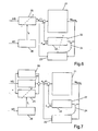
- FIG. 2 a first embodiment of the invention is shown.
- the rotor signal ⁇ (t) detected, for example, by means of the rotor position sensor 16 is fed to a filter 20.
- the filter is designed in this embodiment for the extraction of certain interference signals ⁇ filt (t).
- the interference signal ⁇ filt (t) is fed to a combined disturbance and state calculator 21.
- the filter is designed, for example, as a high-pass or band-pass filter and makes it possible to filter out signal parts which are caused by internal vehicle disturbances.
- the combined disturbance and state calculator 21 is used according to the invention.
- FIG. 3 a schematic diagram of a combined disturbance and state calculator 31 is shown.
- the combined interference and State calculator 31 can be calculated based on a known manipulated variable u and an output variable y, which is measured at the output of a controlled system 32, an internal state variable X and a disturbance ⁇ .
- the controlled system 32 is abstracted as a model and implicitly present.
- the disturbance ⁇ is determined by means of a disturbance variable calculator 33 and the internal state variables X are determined by means of a state calculator 34.
- the output of the disturbance quantity calculator 33 is supplied to the state calculator 34 and the output of the state calculator 34 to the disturbance variable calculator 33.
- the dynamics of a combined disturbance and state calculator 31 can be parameterized by suitable eigenvalue specification as a function of an accuracy of the model of the controlled system 32 and as a function of a measurement noise.
- the application of a combined disturbance and state calculator 21, 31 is particularly suitable for the compensation of disturbance information in a steering system, since the excitation of the disturbance information is in principle unknown and can thus be interpreted as an unknown disturbance, the calculated and as in FIG. 2 represented complementary in the form of a compensation torque M Komp can be switched.
- the inventive method has a particularly low computational effort, since a simple replacement model of the chain of effects of engine torque on the rotor position using the nominal model of an inertial mass of the torque controller 7, so for example the EPS motor is used.
- the rotor signal ⁇ (t) both the rotor position and a rotor speed, which is either derived from the rotor position or measured, can be used.
- the sensor systems mostly present in the vehicles for carrying out the method according to the invention are sufficient.
- Interference information must be suitably extracted from the rotor signal.
- the filter 20 is used, which allows the extraction of certain frequency components from the rotor signal.
- the out Filtered disturbance information ⁇ filt (t) are not caused by the servo assistance or the assist torque of the electric motor.
- the causative moment is taken as the unknown but to be compensated disturbance. Since the disturbance information is excited by the internal vehicle disturbances and not by the requested engine torque, a corresponding compensation torque M Komp can be generated by means of the combined disturbance and state calculator 21.
- the interference signal or portions of the interference signal is reduced or extinguished by the applied compensation signal by applying the electric motor or the torque controller 7 by means of the compensation torque M Komp .
- This has the effect that these components of the interfering signal are no longer contained in the rotor signal and thus also no longer in the filtered interfering signal and thus can no longer be supplied to the combined disturbance and condition calculator 21.
- usually no complete compensation of the interference signal can be performed.
- FIG. 4 an improved embodiment of the method according to the invention is shown, in which the original interference signal is reconstructed.
- a reference model 22 is used, to which the compensation torque M Komp is supplied.
- the reference model 22 is generated, for example, via physical modeling or by means of an identification of the chain of effects "engine torque to rotor position” or “engine torque to rotor speed” carried out, for example, during operation of the vehicle or the steering system.
- a reconstructed interference signal ⁇ rek (t) is consequently generated from the compensation moment M Komp and likewise supplied to the combined disturbance and state calculator 21.
- the filtered signal from the rotor position ⁇ interference signal is filt (t) with the reconstructed interference signal ⁇ rec (t) is superimposed and supplied as a common signal to the combined interference andGoodsberechner 21st
- the reference model 22 is stored, for example, in the memory 5 of the control unit 3.
- FIG. 5 illustrated embodiment of the invention allows a further improvement of the noise compensation.
- a switch-off of the model-based feedback is provided, wherein it is checked within a predeterminable relatively short time interval whether the applied interference signal ⁇ filt (t) and the reconstructed interference signal ⁇ rek (t) are in sufficiently good agreement with regard to their amplitude and their phase position , If this is the case, the model-based feedback is switched on, for example, by activation of a switching element 24.
- This embodiment has the advantage that in the case of a time-variant controlled system or a variation in the chain of effects, the model-based feedback can possibly be deactivated due to production tolerances and a resulting poor or insufficiently matching reference model 22. Nevertheless, compensation can be maintained by means of the combined disturbance and state calculator 21. Thus, although then possibly no complete compensation of the disturbance information longer possible, yet the entire system remains over the entire life cycle of the vehicle in a faultless, albeit limited operating mode.
- an adaptation of the distance model is also carried out if there is a significant amplitude or phase offset.
- the model-based feedback is switched on.
- the identification of the chain of effects itself can be done, for example, by a linear regression based on temporarily stored input and output data.
- a complex storage of a time series of measured values in the control unit is technically, however, usually difficult to realize.
- the adaptation method used is therefore preferably based on the measurements of the current sampling step.
- the model structure of an electric motor for the return clutch is initially assumed to be an inert mass with an unknown speed-proportional damping.
- the parameter of the damping is identified by means of a Kalman filter in a predetermined value range.
- a frequency-variable bandpass 25 are used instead of the fixed filter 20 can - as in the embodiment in FIG. 6 shown - a frequency-variable bandpass 25 are used.
- the center frequencies or corner frequencies of the frequency-variable bandpass filter 25 are adjusted by means of an external signal s (t), wherein the signal s (t) corresponds for example to a wheel speed or a wheel revolving frequency which was determined by means of the sensor 18.
- an excitation frequency is determined, which can be noticed as steering wheel torsional vibrations by the driver, for example, caused by imbalances of the wheels or the brake discs. This in FIG.
- the inventive method or the device according to the invention make it possible in a particularly simple manner, different proportions to specifically compensate for internal vehicle malfunctions. For this no multiple interpretation or implementation of the combined Störund condition calculator is necessary. Rather, it is enough to have a specified one
- Specify transfer function that includes the desired interference suppression over all frequencies.
- a plurality of filters 20, 25 may also be provided, each filter being intended for a particular amount of interference.
- the filters may be combined with one or more frequency variable bandpasses 25.
- the filters 20 different resonant bands and in addition can be attenuated or compensated with one or more frequency-variable bandpasses 25 Lenkradwindschwenkungen.
Abstract
Description
Die Erfindung betrifft ein Verfahren und eine Vorrichtung zur Kompensation von Störinformationen in einem elektrischen Lenksystem in einem Fahrzeug, wobei das Lenksystem einen ansteuerbaren Momentensteller, beispielsweise einen Elektromotor, umfasst und wobei der Momentensteller einen Rotor aufweist.The invention relates to a method and a device for compensation of disturbance information in an electric steering system in a vehicle, wherein the steering system comprises a controllable torque adjuster, for example an electric motor, and wherein the torque adjuster comprises a rotor.
Während des Betriebs eines Fahrzeugs werden dem Fahrer über das Lenksystem Informationen übermittelt. Der Fahrer nimmt diese Informationen am Lenkrad wahr, wobei diese Informationen sowohl Nutzinformationen als auch Störinformationen umfassen. Nutzinformationen werden beispielsweise in Form von Lenkmomenten übermittelt, die eine Rückmeldung über den Fahrbahnreibwert, beziehungsweise einen aktuellen Kontakt zwischen Reifen und Fahrbahnoberfläche, liefern. Weitere Nutzinformationen betreffen beispielsweise Fahrbahnunebenheiten, die vom Fahrer über das Lenksystem am Lenkrad wahrgenommen werden. Derartige Nutzinformationen benötigt der Fahrer, um das Fahrzeug sicher zu steuern.During operation of a vehicle, information is transmitted to the driver via the steering system. The driver perceives this information on the steering wheel, this information including both payload information and clutter information. Payload information is transmitted, for example, in the form of steering torques which provide feedback about the road friction coefficient, or a current contact between the tire and the road surface. Further useful information relates, for example, to uneven road surfaces that are perceived by the driver via the steering system on the steering wheel. Such useful information requires the driver to safely control the vehicle.
Insbesondere auf Niedrigreibwert treten häufig Achsschwingungen bzw. Rattern sowohl beim Parkieren als auch beim Fahren auf, da die Reifen keine dämpfende Wirkung durch den Untergrund mehr erfahren. Rattern kann aber auch durch die Beschaffenheit der Fahrbahnoberfläche bzw. durch deren geschwindigkeitsabhängige Anregungsfrequenz in Kombination mit der Achseigenfrequenz bzw. mit Überhöhungen dessen Amplitudengangs verursacht werden. Diesbezügliche Rückmeldungen durch das Lenksystem sowie Rückmeldungen, die durch interne Fahrzeugstörungen bedingt sind, lenken jedoch regelmäßig den Fahrer während des Betriebs des Fahrzeugs ab beziehungsweise irritieren den Fahrer und erschweren damit ein sicheres Steuern des Fahrzeugs. Fahrzeuginterne Störungen können durch unausgewuchtete Räder (sogenanntes "Smooth Read Shake" oder "Shimmy"), unausgewuchtete oder in der Dicke variierende Bremsscheiben (sogenanntes "Brake Judder") und/oder durch im Gesamtverbund angeregte Resonanzen verursacht werden.In particular, at low friction often occur axle vibrations or rattling both when parking and when driving, as the tires no damping effect through the ground learn more. But rattling can also be caused by the nature of the road surface or by their speed-dependent excitation frequency in combination with the axis natural frequency or with elevations whose amplitude response. Corresponding feedback from the steering system and feedback caused by internal vehicle disturbances, however, regularly distract the driver during operation of the vehicle or irritate the driver, making it difficult to safely control the vehicle. In-vehicle interference can be caused by unbalanced wheels (so-called "Smooth Read Shake" or "Shimmy"), unbalanced or in thickness varying brake discs (so-called "Brake Judder") and / or be caused by in the overall composite excited resonances.
Im Folgenden werden Informationen, deren Rückmeldung durch das Lenksystem die sichere Fahrzeugführung beeinträchtigen, als Störinformation bezeichnet,. Störinformationen lassen sich unterteilen in sinusförmige Störinformationen mit variabler Frequenz sowie unstrukturierte Störanregungen. Shimmy und Brake Judder beispielsweise sind sinusförmige Störinformationen, die durch die Radumlaufdrehzahl der Räder angeregt werden.In the following, information whose feedback from the steering system is detrimental to the safe guidance of the vehicle is referred to as a disturbance information. Interference information can be subdivided into sinusoidal disturbance information with variable frequency as well as unstructured interference excitations. For example, Shimmy and Brake Judders are sinusoidal clutter information that is excited by the wheel rotational speed of the wheels.
Aufgabe der Erfindung ist es, ein Verfahren und eine Vorrichtung bereitzustellen, die eine Reduzierung von an dem Lenkrad wahrnehmbaren Störinformationen ermöglichen, so dass eine Beeinträchtigung des Fahrers durch auf Störinformationen basierende Rückmeldungen reduziert wird. Insbesondere soll mit dem erfindungsgemäßen Verfahren und der Vorrichtung jede Art von Störinformationen reduziert beziehungsweise kompensiert werden können.The object of the invention is to provide a method and a device which enable a reduction of disturbing information perceivable on the steering wheel, so that an impairment of the driver is reduced by feedback based on disturbance information. In particular, with the method and the device according to the invention, any kind of disturbing information can be reduced or compensated.
Die Aufgabe wird durch ein Verfahren mit den Merkmalen des unabhängigen Patentanspruchs 1 gelöst. Weitere Vorteile werden durch die in den Unteransprüchen genannten Ausführungsformen erreicht, wobei unterschiedliche Kombinationen dieser Merkmale - auch wenn dies nicht ausdrücklich erwähnt ist - möglich sind. Die Aufgabe wird ferner durch eine Vorrichtung gemäß dem unabhängigen Patentanspruch 14 gelöst.The object is achieved by a method having the features of
Erfindungsgemäß wird ein Rotorsignal erfasst, wobei das Rotorsignal vorzugsweise eine aktuelle Rotorlage oder eine aktuelle Rotorgeschwindigkeit beschreibt. Hierzu kann beispielsweise ein in dem Fahrzeug bereits vorhandener Rotorlagesensor verwendet werden. Aus dem erfassten Rotorsignal wird beispielsweise mittels eines Filters ein Störsignal extrahiert. Das extrahierte Störsignal wird einem kombinierten Stör- und Zustandsberechner zugeführt, welcher in Abhängigkeit von dem Störsignal ein Kompensationsmoment erzeugt. Das Kompensationsmoment wird dann herangezogen, um das elektrische Lenksystem und dort insbesondere den sogenannten EPS-Motor anzusteuern, so dass aufgrund der Amplitude und/oder der Phasenlage der Kompensationssignale die Störinformationen reduziert oder sogar vollständig neutralisiert werden. Ein kombinierter Stör- und Zustandsberechner, der für das erfindungsgemäße Regelungsverfahren zur Kompensation von Störinformationen eingesetzt werden kann, ist beispielsweise aus
Bei einer Anwendung des erfindungsgemäßen Verfahrens bzw. der erfindungsgemäßen Vorrichtung werden die aus dem Rotorsignal extrahierten Störinformationen durch das Kompensationssignal reduziert. Dies hat aber zur Folge, dass dem kombinierten Stör- und Zustandsberechner keine oder nur noch wenige Störinformationen zugeführt werden können. Deshalb ist es möglich, dass der kombinierte Stör- und Zustandsberechner das Kompensationsmoment nicht mehr zuverlässig bestimmen kann, da der kombinierte Stör- und Zustandsberechner bei der Ausführung des erfindungsgemäßen Verfahrens nicht mehr die tatsächlich im System vorhandenen Störinformationen erhält, sondern die Störinformationen durch das Kompensationsmoment verändert und insbesondere reduziert werden. In einer besonders bevorzugten Ausführungsform ist deshalb eine modelbasierte Rückführung vorgesehen. Hierbei wird das erzeugte Kompensationsmoment einem Referenzmodel zugeführt und es wird mittels des Referenzmodels das Störsignal rekonstruiert. Dies gewährleistet, dass die Störinformationen stets optimal reduziert werden. Bei der bevorzugten Ausführungsform wird folglich die ursprüngliche Störinformation mittels des Referenzmodels rekonstruiert, so dass diese dem kombinierten Stör- und Zustandsberechner erneut zur Verfügung gestellt werden kann. Damit ist ein besonders zuverlässiges und wirkungsvolles Verfahren zur Bestimmung des Kompensationsmoments möglich. Das Referenzmodel entspricht beispielsweise einer physikalischen Modellierung der gesamten Regelstrecke.In an application of the method and the device according to the invention, the noise information extracted from the rotor signal is reduced by the compensation signal. However, this has the consequence that the combined fault and state calculator no or only a few clutter information can be supplied. Therefore, it is possible that the combined disturbance and state calculator can no longer reliably determine the compensation torque, since the combined disturbance and state calculator in the execution of the method according to the invention no longer receives the actual information present in the system, but changes the disturbance information by the compensation torque and in particular be reduced. In a particularly preferred embodiment, therefore, a model-based feedback is provided. In this case, the compensation torque generated is fed to a reference model and the interference signal is reconstructed by means of the reference model. This ensures that the clutter information is always optimally reduced. In the preferred embodiment, therefore, the original interference information is reconstructed by means of the reference model so that it can be made available again to the combined disturbance and state calculator. For a particularly reliable and effective method for determining the compensation torque is possible. The reference model corresponds, for example, to a physical modeling of the entire controlled system.
Gemäß einer weiteren bevorzugten Ausführungsform ist die modelbasierte Rückführung zu- beziehungsweise abschaltbar. Insbesondere kann vorgesehen sein, dass die modelbasierte Rückführung dann zugeschaltet wird, wenn das anliegende Störsignal und das rekonstruierte Störsignal bezüglich ihrer Phasenlage und/oder Amplitude in hinreichender Übereinstimmung sind. Damit wird verhindert, dass durch ein möglicherweise ungenau rekonstruiertes Störsignal die Kompensationsmomente unzutreffend berechnet werden, was möglicherweise zur Erzeugung von weiteren Störinformationen führen könnte. Hierbei ist es von besonderem Vorteil, wenn eine Adaption des Referenzmodels durchgeführt wird, um schließlich eine hinreichende Übereinstimmung des tatsächlich anliegenden Störsignals und des rekonstruierten Störsignals zu erreichen. Vorzugsweise wird während des Betriebs des Fahrzeugs ein Moment aufgeschaltet, um eine Wirkungskette zu ermitteln und insbesondere die Auswirkungen des aufgeschalteten Moments konkret zu erfassen. Die Adaptation des Referenzmodells kann dann in Abhängigkeit von der so ermittelten Wirkungskette durchgeführt werden. Damit wird die Genauigkeit und Zuverlässigkeit des Kompensationsverfahrens nochmals erhöht. Vorzugsweise wird bei der Aufschaltung des Moments ein Moment derart gewählt, dass es von dem Fahrer nicht störend beim Betrieb des Fahrzeugs empfunden wird.According to a further preferred embodiment, the model-based feedback can be switched on or off. In particular, can be provided be that the model-based feedback is then switched on when the applied noise and the reconstructed noise signal with respect to their phase angle and / or amplitude are in sufficient agreement. This prevents that due to a possibly inaccurately reconstructed interference signal, the compensation moments are calculated incorrectly, which could possibly lead to the generation of further clutter information. In this case, it is of particular advantage if an adaptation of the reference model is carried out in order finally to achieve a sufficient correspondence between the actually applied interference signal and the reconstructed interference signal. Preferably, a moment is activated during the operation of the vehicle in order to determine a chain of effects and in particular to detect the effects of the activated torque concretely. The adaptation of the reference model can then be carried out as a function of the thus determined chain of effects. This further increases the accuracy and reliability of the compensation method. Preferably, when the torque is applied, a torque is selected such that it is not distracting to the driver during operation of the vehicle.
Gemäß einer vorteilhaften Ausführungsform umfasst das Referenzmodell eine Modellstruktur eines Elektromotors, die initial als träge Masse mit einer unbekannten, zu der Geschwindigkeit des Elektromotors proportionalen Dämpfung angenommen wird. Damit ist es möglich, im Verlaufe der Adaptation mittels eines Parameters die Dämpfung vorzugeben, so dass durch die Beeinflussung dieses einen Parameters besonders einfach eine wirkungsvolle Adaptation des Referenzmodells erreicht werden kann. Selbstverständlich können daneben weitere Parameter während der Adaptation verändert werden. Vorzugsweise wird die Dämpfung mittels eines Kalmanfilters innerhalb eines vorgegebenen Wertbereichs bestimmt. Das Filter, mittels dessen aus dem Rotorsignal das Störsignal extrahiert wird, kann beispielsweise als Hochpass oder als Bandpass ausgebildet sein. Vorzugsweise ist das Filter als ein variabler Bandpass ausgebildet. Hierbei wird in Abhängigkeit von einer Fahrzeuggeschwindigkeit und/oder in Abhängigkeit von einer mit einer Raddrehzahl korrelierenden Größe eine Anregungsfrequenz gebildet. Es werden dann eine Mittenfrequenz und/oder die Eckfrequenzen des variablen Bandpasses in Abhängigkeit von der Anregungsfrequenz gewählt.According to an advantageous embodiment, the reference model comprises a model structure of an electric motor, which is initially assumed to be inertial mass with an unknown damping proportional to the speed of the electric motor. This makes it possible to specify the damping in the course of the adaptation by means of a parameter, so that by influencing this one parameter an effective adaptation of the reference model can be achieved in a particularly simple manner. Of course, additional parameters can be changed during the adaptation. Preferably, the attenuation is determined by means of a Kalman filter within a predetermined value range. The filter, by means of which the interference signal is extracted from the rotor signal, can be designed, for example, as a high-pass filter or as a bandpass filter. Preferably, the filter is designed as a variable bandpass. In this case, an excitation frequency is formed as a function of a vehicle speed and / or as a function of a variable correlating with a wheel speed. A center frequency and / or the corner frequencies of the variable bandpass are then selected as a function of the excitation frequency.
Das erfindungsgemäße Verfahren beziehungsweise die erfindungsgemäße Vorrichtung zeichnen sich insbesondere dadurch aus, dass eine Mehrzahl von Filtern eingesetzt werden können, mittels derer aus dem Rotorsignal eine Mehrzahl unterschiedlicher Störsignale ermittelt werden können. Die so ermittelten Störsignale können dann gemeinsam dem kombinierten Stör- und Zustandsberechner zugeführt werden. Aus den beispielsweise überlagerten Störsignalen erzeugt der kombinierte Stör- und Zustandsberechner dann ein einziges Kompensationssignal. Alternativ oder ergänzend hierzu kann vorgesehen sein, das Störsignal mittels einer spezifizierten Übertragungsfunktion zu extrahieren, wobei die Übertragungsfunktion die gewünschte Störunterdrückung über alle möglichen Frequenzen beinhaltet.The method according to the invention or the device according to the invention are characterized in particular in that a plurality of filters can be used, by means of which a plurality of different interference signals can be determined from the rotor signal. The interference signals thus determined can then be supplied together to the combined fault and state calculator. From the example superimposed interference signals, the combined disturbance and state calculator then generates a single compensation signal. Alternatively or additionally, it may be provided to extract the interference signal by means of a specified transmission function, wherein the transmission function includes the desired interference suppression over all possible frequencies.
Erfindungsgemäß kann folglich jede Art von Störinformation kompensiert werden, unabhängig davon, ob die Störinformation eine sinusförmige Störung mit variabler Frequenz und/oder eine unstrukturierte Störung umfasst. Außerdem wird erreicht, dass mit ein und demselben System eine Mehrzahl unterschiedlicher Störinformationen kompensiert werden können.Thus, according to the invention, any type of noise information can be compensated regardless of whether the noise information includes a variable frequency sinusoidal noise and / or an unstructured noise. In addition, it is achieved that with the same system, a plurality of different fault information can be compensated.
Weitere Merkmale und Vorteile der Erfindung sind in den Figuren und der folgenden Beschreibung dargestellt. Hierbei können die einzelnen Merkmale unterschiedlicher Ausführungsformen kombiniert werden, sofern dies nicht offensichtlich widersprüchlich ist. In den Figuren zeigen:
-
Figur 1 -
Figur 2 -
Figur 3 eine skizzierte Darstellung eines möglichen grundlegenden Aufbaues eines kombinierten Stör- und Zustandsberechners, -
Figur 4 -
Figur 5 -
Figur 6 eine Ausführungsform der Erfindung, mit einem als frequenzvariablen Bandpass ausgebildeten Filter, -
Figur 7 eine weitere Ausführungsform der Erfindung mit einer Mehrzahl von Filtern zur Extraktion unterschiedliche Störsignale.
-
FIG. 1 a schematic representation of a steering system in a vehicle, -
FIG. 2 a schematic representation of a first embodiment of the invention, -
FIG. 3 a sketch of a possible basic structure of a combined disturbance and state calculator, -
FIG. 4 a further embodiment of the invention with feedback of the compensation torque, -
FIG. 5 An embodiment of the invention with switchable on and off feedback of the compensation torque, -
FIG. 6 an embodiment of the invention, with a trained as a frequency-variable bandpass filter, -
FIG. 7 a further embodiment of the invention with a plurality of filters for extracting different noise.
In
Über eine Signalleitung 6 ist das Steuergerät 3 mit einem Momentensteller 7 verbunden, der beispielsweise als Elektromotor ausgebildet ist, so dass eine Steuerung des Elektromotors beziehungsweise des Momentenstellers 7 durch das Steuergerät 3 ermöglicht wird. Der Elektromotor wirkt über ein Getriebe 8 auf einen Drehstab 9. An dem Drehstab 9 ist ein Lenkmittel, beispielsweise ein Lenkrad 10, angeordnet.Via a signal line 6, the control unit 3 is connected to a torque actuator 7, which is for example designed as an electric motor, so that a control of the electric motor or the torque controller 7 is made possible by the control unit 3. The electric motor acts via a gear 8 on a
Der Momentensteller 7 weist einen Rotor 15 auf. Mittels eines Rotorlagesensors 16 ist die aktuelle Rotorlage erfassbar. Alternativ hierzu könnte mittels eines geeigneten Sensors die aktuelle Rotorgeschwindigkeit erfasst werden. Über eine Datenleitung 17 wird dem Steuergerät 3 das die Rotorlage oder die Rotorgeschwindigkeit beschreibende Rotorsignal zugeführt.The torque adjuster 7 has a
Die Lenkvorrichtung weist ferner ein Lenkgetriebe 11 auf, das als Zahnstangelenkgetriebe ausgebildet ist. Das Lenkgetriebe 11 ist über ein Ritzel 12a und eine Zahnstange 12b auf jeder Fahrzeugseite mit einem Lenkgestänge 13, das jeweils mit einem Rad zusammenwirkt, verbunden. Mittels eines Drehzahlsensors 18 kann eine Raddrehzahl erfasst und über eine Datenleitung 19 an das Steuergerät 3 übermittelt werden. Die Datenleitungen 6, 17 und/oder 19 können in vielfältiger Weise ausgeführt seien. Vorzugsweise wird ein Bussystem zur Kommunikation zwischen dem Steuergerät 3 und den Sensoren beziehungsweise Aktuatoren eingesetzt.The steering device further comprises a
Durch eine geeignete Programmierung des Steuergeräts 3 ist auf dem in
In
In
Die Dynamik eines kombinierten Stör- und Zustandsberechners 31 kann durch geeignete Eigenwertvorgabe in Abhängigkeit von einer Genauigkeit des Modells der Regelstrecke 32 sowie in Abhängigkeit von einem Messrauschen parametrisiert werden.The dynamics of a combined disturbance and
Die Anwendung eines kombinierten Stör- und Zustandsberechners 21, 31 eignet sich besonders zur Kompensation von Störinformationen in einem Lenksystem, da die Anregung der Störinformationen prinzipiell unbekannt ist und somit als unbekannte Störgröße interpretiert werden kann, die berechnet und wie in
Das erfindungsgemäße Verfahren weist einen besonders geringen Rechneraufwand auf, da ein einfaches Ersatzmodel der Wirkungskette von Motormoment auf die Rotorlage anhand des Nominalmodells einer Trägenmasse des Momentenstellers 7, also beispielsweise des EPS-Motors verwendet wird. Als Rotorsignal θ(t) kann sowohl die Rotorlage als auch eine Rotorgeschwindigkeit, die entweder aus der Rotorlage abgeleitet oder aber gemessen wird, verwendet werden. Somit reicht die in den Fahrzeugen meist vorhandene Sensorik zur Durchführung des erfindungsgemäßen Verfahrens aus. Störinformationen müssen geeignet aus dem Rotorsignal extrahiert werden. Hierfür wird das Filter 20 eingesetzt, das die Extraktion gewisser Frequenzanteile aus dem Rotorsignal ermöglicht. Die heraus gefilterten Störinformationen θfilt(t) werden nicht durch die Servounterstützung beziehungsweise das Unterstützungsmoment des Elektromotors hervorgerufen.The inventive method has a particularly low computational effort, since a simple replacement model of the chain of effects of engine torque on the rotor position using the nominal model of an inertial mass of the torque controller 7, so for example the EPS motor is used. As the rotor signal θ (t), both the rotor position and a rotor speed, which is either derived from the rotor position or measured, can be used. Thus, the sensor systems mostly present in the vehicles for carrying out the method according to the invention are sufficient. Interference information must be suitably extracted from the rotor signal. For this purpose, the
Daher wird das verursachende Moment als die unbekannte aber zu kompensierende Störgröße angenommen. Da die Störinformationen durch die internen Fahrzeugstörungen und nicht durch das angeforderte Motormoment angeregt werden, kann mittels des kombinierten Stör- und Zustandsberechners 21 ein entsprechendes Kompensationsmoment MKomp erzeugt werden.Therefore, the causative moment is taken as the unknown but to be compensated disturbance. Since the disturbance information is excited by the internal vehicle disturbances and not by the requested engine torque, a corresponding compensation torque M Komp can be generated by means of the combined disturbance and
Bei Anwendung des erfindungsgemäßen Verfahrens wird durch Beaufschlagung des Elektromotors bzw. des Momentenstellers 7 mittels des Kompensationsmoments MKomp das Störsignal beziehungsweise Anteile des Störsignals durch das anliegende Kompensationssignal verringert oder ausgelöscht. Dies bewirkt, dass diese Anteile des Störsignals nicht mehr in dem Rotorsignal und damit auch nicht mehr in dem gefilterten Störsignal enthalten sind und somit dem kombinierten Stör- und Zustandsberechner 21 nicht mehr zugeführt werden können. Dadurch kann meist keine vollständige Kompensation des Störsignals durchgeführt werden. In
Stimmt das Referenzmodel mit der realen Strecke vollständig überein, so kann die Störung mit dem in
Die in
Vorzugsweise wird zusätzlich zur Validierung, also der Bestimmung der Güte des Referenzmodels und dem davon abhängigem Erzeugen beziehungsweise Aufschalten des rekonstruierten Störsignals θrek(t) in dem Element 23 auch eine Adaptation des Streckenmodels vorgenommen, falls ein signifikanter Amplituden - beziehungsweise Phasenversatz vorliegt. Anhand des aktuell gestellten Motormoments sowie des gemessenen Rotorsignals wird das im Speicher abgelegte Referenzmodel 22 modifiziert, bis eine Übereinstimmung zwischen dem Störsignal und dem rekonstruierten Störsignal erreicht wird. Dann wird die modelbasierte Rückkopplung aufgeschaltet. Die Identifikation der Wirkungskette selbst kann beispielsweise durch eine lineare Regression anhand temporär gespeicherter Eingangs- und Ausgangsdaten erfolgen. Eine aufwendige Speicherung einer Zeitreihe von Messwerten in dem Steuergerät ist technisch jedoch meist schwierig zu realisieren. Das verwendete Adaptationsverfahren beruht daher vorzugsweise auf den Messungen des aktuellen Abtastschrittes. Die Modellstruktur eines Elektromotors für die Rückkupplung wird zunächst als träge Masse mit einer unbekannten geschwindigkeitsproportionalen Dämpfung angenommen. Der Parameter der Dämpfung wird mittels eines Kalmanfilters in einem vorgegebenen Wertebereich identifiziert.Preferably, in addition to the validation, that is to say the determination of the quality of the reference model and the dependent generation or interposition of the reconstructed interference signal θ rek (t) in the
Zur Identifikation der Wirkungskette kann vorgesehen sein, während des Betriebs des Fahrzeugs ein Moment gezielt aufzuschalten. Hierbei muss das Moment jedoch so ausgestaltet sein, dass es von dem Fahrer am Lenkrad nicht wahrgenommen wird.In order to identify the chain of effects, provision can be made for selectively activating a moment during the operation of the vehicle. However, the moment must be designed so that it is not perceived by the driver on the steering wheel.
Statt des festeingestellten Filters 20 kann - wie in der Ausführungsform in
Das erfindungsgemäße Verfahren beziehungsweise die erfindungsgemäße Vorrichtung ermöglichen es in besonders einfacher Weise, verschiedene Anteile von internen Fahrzeugstörungen gezielt zu kompensieren. Hierzu ist keine mehrfache Auslegung beziehungsweise Implementierung des kombinierten Störund Zustandsberechners notwendig. Es genügt vielmehr, eine spezifizierteThe inventive method or the device according to the invention make it possible in a particularly simple manner, different proportions to specifically compensate for internal vehicle malfunctions. For this no multiple interpretation or implementation of the combined Störund condition calculator is necessary. Rather, it is enough to have a specified one
Übertragungsfunktion anzugeben, die die gewünschte Störunterdrückung über alle Frequenzen beinhaltet. Wie in dem Ausführungsbeispiel in
Claims (15)
Applications Claiming Priority (1)
| Application Number | Priority Date | Filing Date | Title |
|---|---|---|---|
| DE200910047586 DE102009047586A1 (en) | 2009-12-07 | 2009-12-07 | Method and device for compensation of interference information in an electric steering system |
Publications (3)
| Publication Number | Publication Date |
|---|---|
| EP2336001A2 true EP2336001A2 (en) | 2011-06-22 |
| EP2336001A3 EP2336001A3 (en) | 2011-12-07 |
| EP2336001B1 EP2336001B1 (en) | 2014-11-05 |
Family
ID=43757884
Family Applications (1)
| Application Number | Title | Priority Date | Filing Date |
|---|---|---|---|
| EP20100189782 Active EP2336001B1 (en) | 2009-12-07 | 2010-12-06 | Method and device for compensating for fault messages in an electrical steering system |
Country Status (2)
| Country | Link |
|---|---|
| EP (1) | EP2336001B1 (en) |
| DE (1) | DE102009047586A1 (en) |
Cited By (2)
| Publication number | Priority date | Publication date | Assignee | Title |
|---|---|---|---|---|
| CN113581277A (en) * | 2020-04-30 | 2021-11-02 | 新乡艾迪威汽车科技有限公司 | Method and system for restraining steering torque fluctuation for EPS |
| WO2022183410A1 (en) * | 2021-03-03 | 2022-09-09 | 浙江吉利控股集团有限公司 | Vehicle control method and system, and vehicle |
Families Citing this family (4)
| Publication number | Priority date | Publication date | Assignee | Title |
|---|---|---|---|---|
| DE102012104253B4 (en) | 2012-01-13 | 2016-07-28 | Robert Bosch Automotive Steering Gmbh | Method and device for compensation of disturbances in an electric steering system |
| DE102014105088A1 (en) * | 2014-04-10 | 2015-10-15 | Dr. Ing. H.C. F. Porsche Aktiengesellschaft | Regulator for an electromechanical steering system, steering system with such a controller and motor vehicle with such a steering system |
| JP6394520B2 (en) | 2015-07-03 | 2018-09-26 | マツダ株式会社 | Control device for electric power steering |
| JP7247508B2 (en) * | 2018-09-28 | 2023-03-29 | 日本電産株式会社 | Steering control device and power steering device |
Family Cites Families (10)
| Publication number | Priority date | Publication date | Assignee | Title |
|---|---|---|---|---|
| JPH03182881A (en) * | 1989-12-11 | 1991-08-08 | Omron Corp | Electrically driven power steering device |
| JP3951205B2 (en) * | 1998-05-19 | 2007-08-01 | 株式会社デンソー | Power steering method and power steering apparatus |
| FR2837161B1 (en) * | 2002-03-13 | 2004-06-11 | Soc Mecanique Irigny | METHOD OF DAMPING THE PARASITIC VIBRATIONS ARISING FROM THE FRONT OF A MOTOR VEHICLE |
| DE10317991A1 (en) * | 2003-04-19 | 2004-10-28 | Volkswagen Ag | System for reducing steering wheel jerkiness in motor vehicle steering |
| DE102004051338A1 (en) * | 2004-10-21 | 2006-04-27 | Bayerische Motoren Werke Ag | Device for reducing steering wheel torsional vibrations on a motor vehicle and operating method therefor |
| DE102005003180B4 (en) * | 2005-01-19 | 2015-04-02 | Volkswagen Ag | Device and method for reducing false excitations on the steering wheel |
| EP2028080B1 (en) * | 2007-08-23 | 2012-01-18 | Ford Global Technologies, LLC | Method for operating an electric power steering system, electronic control unit for an electric power steering system and electric power steering system |
| DE102007040912A1 (en) * | 2007-08-30 | 2009-03-05 | Bayerische Motoren Werke Aktiengesellschaft | Sensor-signal characteristic processing method for motor vehicle, involves eliminating interference portion from signal characteristic, and processing usage portion remained after elimination in chassis frame-regulation system |
| DE102008021856A1 (en) * | 2008-05-02 | 2009-11-05 | Volkswagen Ag | Electromechanical servo steering system for controlling desired steering angle of wheels of vehicle, has adjusting unit for adjusting steering angle of wheels, where supplementary signal is provided dependent on effect of road on wheels |
| DE102008061696A1 (en) * | 2008-12-10 | 2010-06-17 | Volkswagen Ag | Electromechanical steering and method for determining a road condition |
-
2009
- 2009-12-07 DE DE200910047586 patent/DE102009047586A1/en not_active Withdrawn
-
2010
- 2010-12-06 EP EP20100189782 patent/EP2336001B1/en active Active
Non-Patent Citations (1)
| Title |
|---|
| S.KWON; W. K. CHUNG: "Perturbation Compensator based Robust Tracking Control and State Estimation of Mechanical Systems", 2004, SPRINGER VERLAG |
Cited By (2)
| Publication number | Priority date | Publication date | Assignee | Title |
|---|---|---|---|---|
| CN113581277A (en) * | 2020-04-30 | 2021-11-02 | 新乡艾迪威汽车科技有限公司 | Method and system for restraining steering torque fluctuation for EPS |
| WO2022183410A1 (en) * | 2021-03-03 | 2022-09-09 | 浙江吉利控股集团有限公司 | Vehicle control method and system, and vehicle |
Also Published As
| Publication number | Publication date |
|---|---|
| DE102009047586A1 (en) | 2011-06-09 |
| EP2336001B1 (en) | 2014-11-05 |
| EP2336001A3 (en) | 2011-12-07 |
Similar Documents
| Publication | Publication Date | Title |
|---|---|---|
| EP2593347B1 (en) | Method and device for preventing torsional vibrations on a steering system | |
| DE102010025197B4 (en) | Method and device for filtering a setpoint signal | |
| EP2393701B1 (en) | Determining a target steering torque in a steering device | |
| DE102005003180B4 (en) | Device and method for reducing false excitations on the steering wheel | |
| EP2336001B1 (en) | Method and device for compensating for fault messages in an electrical steering system | |
| DE102010030986B4 (en) | Method for determining a rack force for a steering device in a vehicle | |
| DE102010042135B4 (en) | Method for determining a rack force for a steering device in a vehicle | |
| DE102009020157B4 (en) | Method and device for calculating a virtual rotor angle | |
| DE102012104253B4 (en) | Method and device for compensation of disturbances in an electric steering system | |
| DE102009028448B4 (en) | Method and device for recognizing steering wheel torsional vibrations in a steering system and for treating them | |
| DE102010031710A1 (en) | Method for operating electromechanical power steering of motor vehicle, involves applying supporting torque on steering gear of power steering by electrical machine in dependence of steering torque | |
| EP2822838B1 (en) | Method for automatically parking a vehicle including an active steering parking assistance system and a steering superposition device | |
| DE102020213553A1 (en) | Steering system and method of operating a steering system | |
| DE102009055939B4 (en) | Electromechanical steering and method for controlling electromechanical steering | |
| DE102012102629A1 (en) | Method for controlling steering system of motor vehicle, involves controlling controller of steering force through one way path and feedback of steering force through return path, and integrating gain curves into one way and return paths | |
| DE102007012532A1 (en) | Method for operating an electric power steering device | |
| DE102017213415B4 (en) | Method of operating a steering device | |
| DE102012219539B4 (en) | Method and device for controlling a dynamically controlled, electrically power-assisted steering device for vehicles | |
| DE102009000246A1 (en) | Automatic calibration method for index sensor of electronic servo steering system of motor vehicle in driving operation, involves emitting electronic index signal during deflections of servo steering system in neutral position | |
| DE102008021847B4 (en) | Electromechanical steering system and method for controlling an electromechanical steering system | |
| DE102010049431A1 (en) | Method for diagnosis of sensing unit of electromechanical steering system of vehicle, involves comparing active excitation signal and sensor signal, and determining defect of sensor unit based on predetermined defect criterion | |
| DE102010042896B4 (en) | Method and device for generating a roadway feedback in a steering system comprising an electric motor of a vehicle and a corresponding control device | |
| DE102012112484B4 (en) | Method for operating a steering system of a motor vehicle | |
| EP2698303B1 (en) | Method and device for monitoring a determination of a supporting torque | |
| WO2020207939A1 (en) | Method and control unit for determining a steering torque exerted on a steering column of a steering system for a vehicle, and sensor apparatus for a steering system for a vehicle |
Legal Events
| Date | Code | Title | Description |
|---|---|---|---|
| PUAI | Public reference made under article 153(3) epc to a published international application that has entered the european phase |
Free format text: ORIGINAL CODE: 0009012 |
|
| AK | Designated contracting states |
Kind code of ref document: A2 Designated state(s): AL AT BE BG CH CY CZ DE DK EE ES FI FR GB GR HR HU IE IS IT LI LT LU LV MC MK MT NL NO PL PT RO RS SE SI SK SM TR |
|
| AX | Request for extension of the european patent |
Extension state: BA ME |
|
| PUAL | Search report despatched |
Free format text: ORIGINAL CODE: 0009013 |
|
| AK | Designated contracting states |
Kind code of ref document: A3 Designated state(s): AL AT BE BG CH CY CZ DE DK EE ES FI FR GB GR HR HU IE IS IT LI LT LU LV MC MK MT NL NO PL PT RO RS SE SI SK SM TR |
|
| AX | Request for extension of the european patent |
Extension state: BA ME |
|
| RIC1 | Information provided on ipc code assigned before grant |
Ipc: B62D 15/02 20060101ALI20111101BHEP Ipc: B62D 6/00 20060101ALI20111101BHEP Ipc: B62D 5/04 20060101AFI20111101BHEP |
|
| 17P | Request for examination filed |
Effective date: 20111109 |
|
| GRAP | Despatch of communication of intention to grant a patent |
Free format text: ORIGINAL CODE: EPIDOSNIGR1 |
|
| INTG | Intention to grant announced |
Effective date: 20140714 |
|
| GRAS | Grant fee paid |
Free format text: ORIGINAL CODE: EPIDOSNIGR3 |
|
| GRAA | (expected) grant |
Free format text: ORIGINAL CODE: 0009210 |
|
| AK | Designated contracting states |
Kind code of ref document: B1 Designated state(s): AL AT BE BG CH CY CZ DE DK EE ES FI FR GB GR HR HU IE IS IT LI LT LU LV MC MK MT NL NO PL PT RO RS SE SI SK SM TR |
|
| REG | Reference to a national code |
Ref country code: GB Ref legal event code: FG4D Free format text: NOT ENGLISH |
|
| REG | Reference to a national code |
Ref country code: CH Ref legal event code: EP |
|
| REG | Reference to a national code |
Ref country code: AT Ref legal event code: REF Ref document number: 694439 Country of ref document: AT Kind code of ref document: T Effective date: 20141115 |
|
| REG | Reference to a national code |
Ref country code: IE Ref legal event code: FG4D Free format text: LANGUAGE OF EP DOCUMENT: GERMAN |
|
| REG | Reference to a national code |
Ref country code: DE Ref legal event code: R096 Ref document number: 502010008185 Country of ref document: DE Effective date: 20141224 |
|
| REG | Reference to a national code |
Ref country code: NL Ref legal event code: VDEP Effective date: 20141105 |
|
| REG | Reference to a national code |
Ref country code: LT Ref legal event code: MG4D |
|
| PG25 | Lapsed in a contracting state [announced via postgrant information from national office to epo] |
Ref country code: NO Free format text: LAPSE BECAUSE OF FAILURE TO SUBMIT A TRANSLATION OF THE DESCRIPTION OR TO PAY THE FEE WITHIN THE PRESCRIBED TIME-LIMIT Effective date: 20150205 Ref country code: PT Free format text: LAPSE BECAUSE OF FAILURE TO SUBMIT A TRANSLATION OF THE DESCRIPTION OR TO PAY THE FEE WITHIN THE PRESCRIBED TIME-LIMIT Effective date: 20150305 Ref country code: IS Free format text: LAPSE BECAUSE OF FAILURE TO SUBMIT A TRANSLATION OF THE DESCRIPTION OR TO PAY THE FEE WITHIN THE PRESCRIBED TIME-LIMIT Effective date: 20150305 Ref country code: LT Free format text: LAPSE BECAUSE OF FAILURE TO SUBMIT A TRANSLATION OF THE DESCRIPTION OR TO PAY THE FEE WITHIN THE PRESCRIBED TIME-LIMIT Effective date: 20141105 Ref country code: ES Free format text: LAPSE BECAUSE OF FAILURE TO SUBMIT A TRANSLATION OF THE DESCRIPTION OR TO PAY THE FEE WITHIN THE PRESCRIBED TIME-LIMIT Effective date: 20141105 Ref country code: FI Free format text: LAPSE BECAUSE OF FAILURE TO SUBMIT A TRANSLATION OF THE DESCRIPTION OR TO PAY THE FEE WITHIN THE PRESCRIBED TIME-LIMIT Effective date: 20141105 Ref country code: NL Free format text: LAPSE BECAUSE OF FAILURE TO SUBMIT A TRANSLATION OF THE DESCRIPTION OR TO PAY THE FEE WITHIN THE PRESCRIBED TIME-LIMIT Effective date: 20141105 |
|
| RAP2 | Party data changed (patent owner data changed or rights of a patent transferred) |
Owner name: ROBERT BOSCH AUTOMOTIVE STEERING GMBH |
|
| PG25 | Lapsed in a contracting state [announced via postgrant information from national office to epo] |
Ref country code: PL Free format text: LAPSE BECAUSE OF FAILURE TO SUBMIT A TRANSLATION OF THE DESCRIPTION OR TO PAY THE FEE WITHIN THE PRESCRIBED TIME-LIMIT Effective date: 20141105 Ref country code: LV Free format text: LAPSE BECAUSE OF FAILURE TO SUBMIT A TRANSLATION OF THE DESCRIPTION OR TO PAY THE FEE WITHIN THE PRESCRIBED TIME-LIMIT Effective date: 20141105 Ref country code: CY Free format text: LAPSE BECAUSE OF FAILURE TO SUBMIT A TRANSLATION OF THE DESCRIPTION OR TO PAY THE FEE WITHIN THE PRESCRIBED TIME-LIMIT Effective date: 20141105 Ref country code: SE Free format text: LAPSE BECAUSE OF FAILURE TO SUBMIT A TRANSLATION OF THE DESCRIPTION OR TO PAY THE FEE WITHIN THE PRESCRIBED TIME-LIMIT Effective date: 20141105 Ref country code: RS Free format text: LAPSE BECAUSE OF FAILURE TO SUBMIT A TRANSLATION OF THE DESCRIPTION OR TO PAY THE FEE WITHIN THE PRESCRIBED TIME-LIMIT Effective date: 20141105 Ref country code: GR Free format text: LAPSE BECAUSE OF FAILURE TO SUBMIT A TRANSLATION OF THE DESCRIPTION OR TO PAY THE FEE WITHIN THE PRESCRIBED TIME-LIMIT Effective date: 20150206 Ref country code: HR Free format text: LAPSE BECAUSE OF FAILURE TO SUBMIT A TRANSLATION OF THE DESCRIPTION OR TO PAY THE FEE WITHIN THE PRESCRIBED TIME-LIMIT Effective date: 20141105 |
|
| REG | Reference to a national code |
Ref country code: DE Ref legal event code: R081 Ref document number: 502010008185 Country of ref document: DE Owner name: ROBERT BOSCH AUTOMOTIVE STEERING GMBH, DE Free format text: FORMER OWNER: ZF LENKSYSTEME GMBH, 73527 SCHWAEBISCH GMUEND, DE Effective date: 20150423 |
|
| PG25 | Lapsed in a contracting state [announced via postgrant information from national office to epo] |
Ref country code: BE Free format text: LAPSE BECAUSE OF NON-PAYMENT OF DUE FEES Effective date: 20141231 |
|
| PG25 | Lapsed in a contracting state [announced via postgrant information from national office to epo] |
Ref country code: RO Free format text: LAPSE BECAUSE OF FAILURE TO SUBMIT A TRANSLATION OF THE DESCRIPTION OR TO PAY THE FEE WITHIN THE PRESCRIBED TIME-LIMIT Effective date: 20141105 Ref country code: SK Free format text: LAPSE BECAUSE OF FAILURE TO SUBMIT A TRANSLATION OF THE DESCRIPTION OR TO PAY THE FEE WITHIN THE PRESCRIBED TIME-LIMIT Effective date: 20141105 Ref country code: EE Free format text: LAPSE BECAUSE OF FAILURE TO SUBMIT A TRANSLATION OF THE DESCRIPTION OR TO PAY THE FEE WITHIN THE PRESCRIBED TIME-LIMIT Effective date: 20141105 Ref country code: CZ Free format text: LAPSE BECAUSE OF FAILURE TO SUBMIT A TRANSLATION OF THE DESCRIPTION OR TO PAY THE FEE WITHIN THE PRESCRIBED TIME-LIMIT Effective date: 20141105 Ref country code: DK Free format text: LAPSE BECAUSE OF FAILURE TO SUBMIT A TRANSLATION OF THE DESCRIPTION OR TO PAY THE FEE WITHIN THE PRESCRIBED TIME-LIMIT Effective date: 20141105 |
|
| REG | Reference to a national code |
Ref country code: CH Ref legal event code: PL |
|
| REG | Reference to a national code |
Ref country code: DE Ref legal event code: R097 Ref document number: 502010008185 Country of ref document: DE |
|
| PG25 | Lapsed in a contracting state [announced via postgrant information from national office to epo] |
Ref country code: MC Free format text: LAPSE BECAUSE OF FAILURE TO SUBMIT A TRANSLATION OF THE DESCRIPTION OR TO PAY THE FEE WITHIN THE PRESCRIBED TIME-LIMIT Effective date: 20141105 |
|
| PLBE | No opposition filed within time limit |
Free format text: ORIGINAL CODE: 0009261 |
|
| STAA | Information on the status of an ep patent application or granted ep patent |
Free format text: STATUS: NO OPPOSITION FILED WITHIN TIME LIMIT |
|
| REG | Reference to a national code |
Ref country code: IE Ref legal event code: MM4A |
|
| REG | Reference to a national code |
Ref country code: FR Ref legal event code: ST Effective date: 20150831 |
|
| 26N | No opposition filed |
Effective date: 20150806 |
|
| GBPC | Gb: european patent ceased through non-payment of renewal fee |
Effective date: 20150205 |
|
| PG25 | Lapsed in a contracting state [announced via postgrant information from national office to epo] |
Ref country code: CH Free format text: LAPSE BECAUSE OF NON-PAYMENT OF DUE FEES Effective date: 20141231 Ref country code: IE Free format text: LAPSE BECAUSE OF NON-PAYMENT OF DUE FEES Effective date: 20141206 Ref country code: LI Free format text: LAPSE BECAUSE OF NON-PAYMENT OF DUE FEES Effective date: 20141231 |
|
| PG25 | Lapsed in a contracting state [announced via postgrant information from national office to epo] |
Ref country code: FR Free format text: LAPSE BECAUSE OF NON-PAYMENT OF DUE FEES Effective date: 20150105 |
|
| PG25 | Lapsed in a contracting state [announced via postgrant information from national office to epo] |
Ref country code: IT Free format text: LAPSE BECAUSE OF FAILURE TO SUBMIT A TRANSLATION OF THE DESCRIPTION OR TO PAY THE FEE WITHIN THE PRESCRIBED TIME-LIMIT Effective date: 20141105 |
|
| PG25 | Lapsed in a contracting state [announced via postgrant information from national office to epo] |
Ref country code: GB Free format text: LAPSE BECAUSE OF NON-PAYMENT OF DUE FEES Effective date: 20150205 |
|
| PG25 | Lapsed in a contracting state [announced via postgrant information from national office to epo] |
Ref country code: SI Free format text: LAPSE BECAUSE OF FAILURE TO SUBMIT A TRANSLATION OF THE DESCRIPTION OR TO PAY THE FEE WITHIN THE PRESCRIBED TIME-LIMIT Effective date: 20141105 |
|
| PG25 | Lapsed in a contracting state [announced via postgrant information from national office to epo] |
Ref country code: SM Free format text: LAPSE BECAUSE OF FAILURE TO SUBMIT A TRANSLATION OF THE DESCRIPTION OR TO PAY THE FEE WITHIN THE PRESCRIBED TIME-LIMIT Effective date: 20141105 |
|
| PG25 | Lapsed in a contracting state [announced via postgrant information from national office to epo] |
Ref country code: BG Free format text: LAPSE BECAUSE OF FAILURE TO SUBMIT A TRANSLATION OF THE DESCRIPTION OR TO PAY THE FEE WITHIN THE PRESCRIBED TIME-LIMIT Effective date: 20141105 |
|
| PG25 | Lapsed in a contracting state [announced via postgrant information from national office to epo] |
Ref country code: HU Free format text: LAPSE BECAUSE OF FAILURE TO SUBMIT A TRANSLATION OF THE DESCRIPTION OR TO PAY THE FEE WITHIN THE PRESCRIBED TIME-LIMIT; INVALID AB INITIO Effective date: 20101206 Ref country code: MT Free format text: LAPSE BECAUSE OF FAILURE TO SUBMIT A TRANSLATION OF THE DESCRIPTION OR TO PAY THE FEE WITHIN THE PRESCRIBED TIME-LIMIT Effective date: 20141105 Ref country code: LU Free format text: LAPSE BECAUSE OF NON-PAYMENT OF DUE FEES Effective date: 20141206 Ref country code: TR Free format text: LAPSE BECAUSE OF FAILURE TO SUBMIT A TRANSLATION OF THE DESCRIPTION OR TO PAY THE FEE WITHIN THE PRESCRIBED TIME-LIMIT Effective date: 20141105 |
|
| REG | Reference to a national code |
Ref country code: AT Ref legal event code: MM01 Ref document number: 694439 Country of ref document: AT Kind code of ref document: T Effective date: 20151206 |
|
| PG25 | Lapsed in a contracting state [announced via postgrant information from national office to epo] |
Ref country code: AT Free format text: LAPSE BECAUSE OF NON-PAYMENT OF DUE FEES Effective date: 20151206 |
|
| PG25 | Lapsed in a contracting state [announced via postgrant information from national office to epo] |
Ref country code: MK Free format text: LAPSE BECAUSE OF FAILURE TO SUBMIT A TRANSLATION OF THE DESCRIPTION OR TO PAY THE FEE WITHIN THE PRESCRIBED TIME-LIMIT Effective date: 20141105 |
|
| PG25 | Lapsed in a contracting state [announced via postgrant information from national office to epo] |
Ref country code: AL Free format text: LAPSE BECAUSE OF FAILURE TO SUBMIT A TRANSLATION OF THE DESCRIPTION OR TO PAY THE FEE WITHIN THE PRESCRIBED TIME-LIMIT Effective date: 20141105 |
|
| REG | Reference to a national code |
Ref country code: DE Ref legal event code: R081 Ref document number: 502010008185 Country of ref document: DE Owner name: ROBERT BOSCH GMBH, DE Free format text: FORMER OWNER: ROBERT BOSCH AUTOMOTIVE STEERING GMBH, 73527 SCHWAEBISCH GMUEND, DE |
|
| PGFP | Annual fee paid to national office [announced via postgrant information from national office to epo] |
Ref country code: DE Payment date: 20230223 Year of fee payment: 13 |