EP2335640A1 - Dispositif de positionnement pour l'usage avec analogues et modèles dentaires - Google Patents
Dispositif de positionnement pour l'usage avec analogues et modèles dentaires Download PDFInfo
- Publication number
- EP2335640A1 EP2335640A1 EP09180197A EP09180197A EP2335640A1 EP 2335640 A1 EP2335640 A1 EP 2335640A1 EP 09180197 A EP09180197 A EP 09180197A EP 09180197 A EP09180197 A EP 09180197A EP 2335640 A1 EP2335640 A1 EP 2335640A1
- Authority
- EP
- European Patent Office
- Prior art keywords
- model
- physical
- analog
- respect
- dental
- Prior art date
- Legal status (The legal status is an assumption and is not a legal conclusion. Google has not performed a legal analysis and makes no representation as to the accuracy of the status listed.)
- Granted
Links
- 239000007943 implant Substances 0.000 claims description 82
- 238000000034 method Methods 0.000 claims description 78
- 125000006850 spacer group Chemical group 0.000 claims description 77
- 239000000463 material Substances 0.000 claims description 42
- 239000004053 dental implant Substances 0.000 claims description 39
- 210000004513 dentition Anatomy 0.000 claims description 33
- 230000036346 tooth eruption Effects 0.000 claims description 33
- 230000000295 complement effect Effects 0.000 claims description 24
- 210000002455 dental arch Anatomy 0.000 claims description 6
- 238000004519 manufacturing process Methods 0.000 description 54
- 210000000214 mouth Anatomy 0.000 description 44
- 238000003754 machining Methods 0.000 description 14
- 230000013011 mating Effects 0.000 description 14
- 239000002131 composite material Substances 0.000 description 9
- 238000005266 casting Methods 0.000 description 7
- 239000000945 filler Substances 0.000 description 7
- 230000010485 coping Effects 0.000 description 6
- 230000035876 healing Effects 0.000 description 6
- 239000011505 plaster Substances 0.000 description 6
- 210000001519 tissue Anatomy 0.000 description 6
- 238000004891 communication Methods 0.000 description 5
- 238000013461 design Methods 0.000 description 5
- 238000011065 in-situ storage Methods 0.000 description 4
- 238000002513 implantation Methods 0.000 description 3
- 238000003801 milling Methods 0.000 description 3
- 230000003287 optical effect Effects 0.000 description 3
- 239000000523 sample Substances 0.000 description 3
- 238000012546 transfer Methods 0.000 description 3
- 238000004873 anchoring Methods 0.000 description 2
- 210000000988 bone and bone Anatomy 0.000 description 2
- 210000000887 face Anatomy 0.000 description 2
- 238000001727 in vivo Methods 0.000 description 2
- 238000003780 insertion Methods 0.000 description 2
- 230000037431 insertion Effects 0.000 description 2
- 230000003993 interaction Effects 0.000 description 2
- 230000002441 reversible effect Effects 0.000 description 2
- 239000000853 adhesive Substances 0.000 description 1
- 230000001070 adhesive effect Effects 0.000 description 1
- 239000004568 cement Substances 0.000 description 1
- 238000010586 diagram Methods 0.000 description 1
- 230000000694 effects Effects 0.000 description 1
- 239000003822 epoxy resin Substances 0.000 description 1
- 210000001847 jaw Anatomy 0.000 description 1
- 238000010297 mechanical methods and process Methods 0.000 description 1
- 229920000647 polyepoxide Polymers 0.000 description 1
- 238000002360 preparation method Methods 0.000 description 1
- 238000012545 processing Methods 0.000 description 1
- 230000000717 retained effect Effects 0.000 description 1
- 239000003826 tablet Substances 0.000 description 1
- 230000000007 visual effect Effects 0.000 description 1
Images


Classifications
-
- A—HUMAN NECESSITIES
- A61—MEDICAL OR VETERINARY SCIENCE; HYGIENE
- A61C—DENTISTRY; APPARATUS OR METHODS FOR ORAL OR DENTAL HYGIENE
- A61C9/00—Impression cups, i.e. impression trays; Impression methods
- A61C9/002—Means or methods for correctly replacing a dental model, e.g. dowel pins; Dowel pin positioning means or methods
-
- A—HUMAN NECESSITIES
- A61—MEDICAL OR VETERINARY SCIENCE; HYGIENE
- A61C—DENTISTRY; APPARATUS OR METHODS FOR ORAL OR DENTAL HYGIENE
- A61C11/00—Dental articulators, i.e. for simulating movement of the temporo-mandibular joints; Articulation forms or mouldings
- A61C11/08—Dental articulators, i.e. for simulating movement of the temporo-mandibular joints; Articulation forms or mouldings with means to secure dental casts to articulator
Definitions
- This invention relates to dental implants, in particular to methods, systems and accessories useful in procedures relating to dental implants.
- Endosseous implants are widely used as artificial substitutes for the root portion of missing teeth, and allow a tooth prosthesis to be securely anchored to the jaw via a permanent abutment mounted to the implant.
- Endosseous implants generally comprise an externally threaded body, often self-taping into the bone tissues, and further comprise an internal chamber that is configured, typically internally threaded, for receiving and securing therein the anchoring stem of a permanent abutment therein.
- an impression abutment is mounted to the implant so that it projects into the intra oral cavity, and an impression is then obtained of the intraoral cavity using well known techniques and impression materials, for example PVS.
- the impression abutment may be of the pick-up type, to be embedded with the impression material and retained therein after the impression tray is removed.
- the impression tray is removed without the impression abutment attached thereto, but nevertheless having a recess formed therein complementary to the outer shape of the impression abutment, enabling the transfer-type impression abutment to be mounted therein at a later time.
- an analog corresponding to the particular implant that is implanted in the patient, is attached to the abutment, which is in situ in the impression material, and plaster is poured into the impression tray including the analog to produce a positive plaster model of the intraoral cavity with the analog embedded.
- the analog in particular the internal passage thereof which is substantially identical to the internal passage of the implant that is designed to receive, engage and secure the permanent abutment, is in a position and orientation in the plaster model corresponding to the position and orientation of the implant in the patient's intra oral cavity.
- the dental technician can now attach a permanent abutment, or custom design a permanent abutment to fit the implant, build a coping or bridge framework or prosthesis to fit into the intraoral cavity of the patient.
- virtual model is used herein synonymously with "numerical entity”, “3D model”, and other such terms, and relates to a virtual representation in a computer environment of a real object, for example a dentition or at least a part of an intraoral cavity, or of a real (physical) model thereof, for example.
- scanning refer to any procedure directed at obtaining 3D topographic data of a surface, particularly of a dental surface, and thus includes mechanical methods, typically based on 3D probes for example, optical methods, including for example confocal methods, for example as disclosed in WO 00/08415 , the contents of which are incorporated herein in their entirety by reference, or indeed any other method.
- display refers to any means or method for delivering a presentation, which may include any information, data, images, sounds, etc, and thus the delivery may be in visual and/or audio form.
- a method and system for manufacturing a physical dental model A virtual model is provided representative of at least a portion of the intra-oral cavity including at least one dental implant implanted therein, and the virtual model includes a virtual portion representative of each dental implant.
- the virtual spatial disposition of each such virtual portion is determined with respect to the virtual model, corresponding to a real spatial disposition of the respective implant with respect to the intra oral cavity.
- a physical model is then manufactured based on the virtual model, the physical model including a physical analog corresponding to each implant at a respective physical spatial disposition with respect to the physical model corresponding to the respective virtual spatial disposition of the respective virtual portion with respect to the first virtual model as already determined.
- a jig may be provided configured for maintaining a desired physical spatial disposition between the physical analog and a cavity of the physical dental model at least until the physical analog is affixed in the cavity.
- a method for manufacturing a physical dental model comprising
- the first virtual model may be generated in any suitable manner - for example by scanning the intraoral cavity in vivo, or scanning a positive, negative or composite physical model of the intraoral cavity that includes representations of the implant(s) and a part of the dentition in the vicinity the implant(s).
- step (b) comprises providing a second virtual model at least partially representative of the or each respective said physical analog, and incorporating said second virtual model with said first virtual model based on said determination of the respective said virtual spatial disposition, to generate a third virtual model, wherein in step (c), said manufacturing of said physical model is based on said third virtual model.
- step (b) may comprise manipulating the or each said second virtual model into an aligned spatial disposition with respect to the respective said virtual spatial disposition, and generating said third virtual model based on the first virtual model and including a virtual cavity (i.e. a virtual representation of the cavity) for virtually receiving and accommodating the or each respective second virtual model therein in a manner corresponding to that required for the respective physical analog with respect to said physical model of the intra oral cavity.
- a virtual cavity i.e. a virtual representation of the cavity
- Step (c) may comprise forming an outer model surface corresponding to dental surfaces of said portion of the intra oral cavity, and forming a recess in said physical model (corresponding to the virtual cavity) for accommodating a respective said analog at the respective said physical spatial disposition, said recess corresponding to the respective said virtual cavity.
- At least one said virtual cavity is generated having a form generally complementary to that of the respective said physical analog, such that the respective said recess formed in said physical model provides a friction fit with respect to the respective said physical analog to accommodate the respective said physical analog at the respective said physical spatial disposition.
- At least one said virtual cavity is generated having a form generally complementary to that of the respective said physical analog including a jacket, such that the respective said recess formed in said physical model provides a significant clearance gap with respect to the respective said physical analog
- said respective physical analog comprises said jacket formed of suitable model material, said jacket having an external form substantially complementary to that of the respective said recess, to enable the respective physical analog including the respective jacket to be accommodated in the respective said recess at the respective said physical spatial disposition.
- the said external form for the respective said jacket may be configured for fixing the spatial disposition thereof in the respective said recess in six degrees of freedom.
- the jacket may be formed by a casting process applied to the respective said physical analog, or by applying a layer of said model material on the respective physical analog, and CNC machining said layer to provide the respective said external form.
- At least one said virtual cavity is generated having a form generally complementary to that of the respective said physical analog, such that the respective said recess formed in said physical model provides a significant clearance gap with respect to the respective said physical analog, wherein a suitable filler material is applied to fill the clearance gap, to enable the respective physical analog including the respective jacket to be accommodated in the respective said recess at the respective said physical spatial disposition.
- the filler material may comprise a suitable cementing material.
- a suitable jig may be used for maintaining a said physical spatial disposition between the respective physical analog and the respective cavity at least until the physical analog is affixed therein by means of the filler material.
- the jig may comprise a base that is mounted in fixed spatial relationship to the physical dental model, for example affixed to a portion of the physical model, at least until the physical analog is affixed therein.
- said portion of the physical model does not include physical model representations of teeth adjacent to a said implant.
- step (c) comprises forming an outer model surface corresponding to dental surfaces of said portion of the intra oral cavity from a blank of model material, wherein said blank integrally includes the or each said physical analog in relative spatial dispositions to one another corresponding to the relative spatial dispositions of the or each dental implants with respect to one another in said portion of the intra oral cavity.
- step (d) comprises computer controlled manufacture of at least a portion of said physical model.
- step (d) may comprise manufacturing said physical model via a material removal operation applied to a blank of material or a rapid prototyping process.
- a physical model is manufactured with a hole configured for providing a friction fit with the analog.
- the analog is embedded in a suitable material, which is milled for a close fit with the hole, which may be useful, for example, when the analog is of a shape that does not allow friction fitting.
- the model is manufactured with a relatively large cavity such as to provide a loose fit for the analog, which is cemented in place while held in a jig.
- a plaster blank is cast with the analog embedded in a particular known position.
- the blank is then machined to ensure that the analogue is in the correct desired position/orientation with respect to the other parts (e.g., model dental surfaces) of the finished physical model.
- a system for manufacturing a physical dental model of an intra-oral cavity comprising:
- the manufacturing system is computer controlled.
- the manufacturing system may be configured for manufacturing said physical model via a material removal operation applied to a blank of material, or via a rapid prototyping technique.
- accessories including one or more of a physical tooth model and a jig.
- a jig for maintaining a desired spatial disposition between a respective analog and the respective cavity of a physical model of an intra oral cavity at least until the analog is affixed therein, wherein the jig comprises a base configured for being mounted to a portion of the physical model not including portions representative of adjacent teeth with respect to an implant site.
- a method for modifying a physical dental model comprising:
- the method according to this aspect of the invention may comprise one or more of the elements and features as provided herein regarding the first aspect of the invention, mutatis mutandis.
- an accessory in the form of a jig configured for maintaining a desired physical spatial disposition between a physical analog and a cavity of a physical dental model at least until the physical analog is affixed in said cavity.
- the cavity is an analog receiving cavity formed in said model and for configured for enabling the analog to be affixed in the cavity in said spatial disposition such as to provide a desired spatial disposition between the analog and the dental model.
- the cavity is typically larger (wider and/or deeper than the part of the analog that needs to be embedded in the physical model providing a fillable clearance gap therebetween, and the analog is ultimately secured in the cavity via a suitable filler material, for example.
- the jig may comprise a strut having a first end configured for being mounted with respect to the dental model at a first spatial disposition with respect thereto, and a second end configured for enabling the physical analog to mounted to the second end at a second spatial disposition with respect thereto, wherein said first end is at a third spatial disposition with respect to said second end, and wherein said first spatial disposition, said second spatial disposition and said third spatial disposition are chosen to provide said desired physical spatial disposition between the physical analog and the cavity when said strut is mounted with respect to the dental model and the physical analog is mounted to said strut.
- the jig may additionally or alternatively comprise a spacer member, wherein said strut comprises an elongate arm comprising said first end and said second end at opposed longitudinal ends of said elongate arm, wherein said first end comprises a strut base portion configured for being mounted to the dental model via said spacer member wherein to provide said first spatial disposition between said first end and the dental model.
- Said strut base portion may be configured for enabling said spacer member to be mounted to said strut by engagement to the strut base portion.
- At least one of the strut base portion and said spacer member may comprise a first engagement arrangement to ensure that the spacer member may be mounted to the strut base portion in a spatial disposition with respect thereto that is fixed in six degrees of freedom.
- the first engagement arrangement may comprise at least two laterally spaced pins projecting from a second spacer end of said spacer member and corresponding complementary wells formed in the strut base portion for receiving each said pin.
- Other alternative configurations for the first engagement arrangement may of course be provided.
- the dental model in at least some of the above embodiments may include a model base portion configured for enabling said spacer member to be mounted to the dental model by engagement to the model base portion.
- At least one of the model base portion and said spacer member may comprise a second engagement arrangement to ensure that the spacer may be mounted to the model base portion in a spatial disposition with respect thereto that is fixed in six degrees of freedom.
- said second engagement arrangement may comprise at least two laterally spaced pins projecting from a first spacer end of said spacer member and corresponding complementary wells formed in the model base portion for receiving each said pin.
- Other alternative configurations for the second engagement arrangement may of course be provided.
- said spacer comprises a first spacer end and a second spacer end, wherein said first spacer end is configured for being mounted to said first end via said strut base portion in a spatial disposition with respect thereto that is fixed in six degrees of freedom, and wherein said second spacer end is configured for being mounted to the dental model via a model base portion of the dental model in a spatial disposition with respect to the model base portion that is fixed in six degrees of freedom.
- the geometric form of the jig in particular the specific spatial dispositions of the various parts thereof to properly mate with the physical dental model, can be based on the method provided according to the first aspect of the invention.
- the jig according to at least one of the above embodiments may be integrally produced from a suitable blank via a material removal operation or integrally produced via a suitable rapid prototyping operation, based on the geometric form previously determined.
- a jig particularly useful for dental implant procedures comprising:
- said desired physical spatial disposition of the physical analog with respect to the dental model corresponds to a spatial disposition of a dental implant corresponding to the analog with respect to the real dentition that is being represented by the dental model.
- kit particularly useful for dental implant procedures comprising:
- the jig may comprise a spacer member and a strut, said strut comprising a strut base portion configured for being mounted to said dental model via said spacer member, and a strut end configured for holding the physical analog thereat.
- the dental model may comprise a model base portion configured for enabling said spacer member to be mounted to the dental model by engagement to the model base portion.
- the spacer may comprise a first spacer end and a second spacer end, wherein said first spacer end is configured for being mounted to said strut via said strut base portion in a spatial disposition with respect thereto that is fixed in six degrees of freedom, and wherein said second spacer end is configured for being mounted to the dental model via said model base portion of the dental model in a spatial disposition with respect to the model base portion that is fixed in six degrees of freedom.
- the model dentition is generally representative of a set of adjacent real teeth of a first dental arch of a patient, and may comprise a set of model teeth corresponding to a set of real teeth of at least a portion of a first dental arch of a patient, and wherein said cavity is located adjacent at least one said model tooth at a position corresponding to a missing tooth in the real dentition.
- the kit may optionally further comprise an auxiliary dental model representative of a second real dentition of at least a portion of a second dental arch of the patient, wherein the second real dentition is occlusally opposed with respect to the first real dentition.
- the auxiliary dental model may be configured for being mounted with respect to said dental model in an occlusal relationship corresponding to that between said first real dentition and said second real dentition. This may be accomplished by mounting the two models to the spacer, or to a suitable articulator, for example.
- Fig. 2 illustrates a block diagram of a method 400 for use in dental implant procedures according to an embodiment of the invention
- Fig. 1 illustrates the main elements of a system 200 for carrying out the method according to an embodiment of the invention.
- the present description is directed to a single implant, it is readily appreciated that the invention is applicable, mutatis mutandis, to a plurality of implants that may be implanted in the intra oral cavity of a patient, whether the implants are independent from one another, each being used for a separate prosthesis, or whether at least some of the implants are to be coupled to be used together for a single bridge prosthesis or other multiple tooth prostheses, for example.
- the system 200 comprises: a first module, including a scanner 250 , and a microprocessor or any other suitable computer system 260 ; a second module comprising a physical analog 230 corresponding to the implant 240 that it is desired to have implanted in the intra oral cavity of a patient; and a manufacturing system 280 for manufacturing a physical model 600 of the intra oral cavity including the analog 230 .
- the computer system 260 comprises an input interface or module 210 such as a keyboard, mouse, tablet, and so on, an output device or display means or module 220 , typically a screen or monitor but may additionally or alternatively include a printer, or any other display system, a processing unit or module 230 such as for example a CPU, and a memory 235.
- an input interface or module 210 such as a keyboard, mouse, tablet, and so on
- an output device or display means or module 220 typically a screen or monitor but may additionally or alternatively include a printer, or any other display system
- a processing unit or module 230 such as for example a CPU, and a memory 235.
- the scanner 250 is configured for providing surface data of surfaces, in particular hard dental surfaces, other tissue surfaces of the intra oral cavity of a patient, and of the implant 240 , in situ or before implantation, and is also operatively connected to the computer system 260 and interacts therewith.
- the computer system 260 is suitably programmed for reconstructing such surfaces from the surface data provided to provide a first virtual model 500 of the intraoral cavity.
- Such a scanner may comprise, for example, a probe for determining three dimensional structure by confocal focusing of an array of light beams, for example as marketed under the name of iTero or as disclosed in WO 00/08415 , the contents of which are incorporated herein in their entirety.
- the required scanning may be accomplished using any suitable scanning apparatus for example comprising a hand held probe.
- color data of the intraoral cavity may also provided together with the 3D data, and thus the first virtual model 500 comprises spatial and color information of the dental surfaces scanned. Examples of such scanners are disclosed in US 2006-0001739 , and which is assigned to the present Assignee. The contents of the aforesaid co-pending application are incorporated herein by reference in their entirety.
- the physical analog 230 comprises a housing 234 having an inner passage or chamber 231 , for example including a hexagonal entrance and internally threaded portion, that enables mating with a complementary structure in the permanent abutment, enabling the latter's position with respect to the analog (and thus the physical tooth model) to be dictated in six degrees of freedom.
- the inner chamber 231 thus corresponds and is nominally identical to the inner chamber 241 of the implant 240 .
- the external form of housing 234 is configured for being embedded in a physical model 600 of the intraoral cavity.
- the manufacturing system 280 comprises a computer controlled manufacturing system configured for manufacturing a physical model from a virtual model, with respect to a machine coordinate system C.
- the manufacturing process itself is a material removing process such as CNC milling, the physical model 600 incorporating, or being capable of incorporating, the physical analog 230 in the correct spatial orientation and position with respect to the physical model of intraoral cavity corresponding to the spatial orientation and position of the implant 240 in the patient's intra oral cavity.
- process 400 broadly includes the following steps:
- step 410 comprises implanting at least one implant in an intra oral cavity of a patient, and follows well-established dental procedures in the art, which will not be described in further detail herein.
- Step 420 comprises acquiring an accurate 3D representation, (herein also referred to interchangeably as "three-dimensional model”, “ 3D model”, “virtual model” and the like) of the required part of the intraoral cavity of the patient, which forms the focus of the particular implant procedure for a particular patient and regarding which it is desired to obtain the 3D topographical or surface data thereof.
- the required part may include partial or the full mandibular or maxillary arches, or both arches, and may further include details of the spatial relationship between the two arches in occlusion, and includes the implant in situ in the intra oral cavity.
- this first virtual model 500 may be provided by scanning the intra-oral cavity in-vivo using any suitable equipment for scanning a patient's teeth.
- scanning equipment comprises, in this embodiment, the scanner 250 of system 200 , though in other embodiments, any other suitable scanner may be used.
- the 3D digitized data may be obtained in any other suitable manner, including other suitable intra oral scanning techniques, based on optical methods, direct contact methods or any other means, applied directly to the patient's dentition.
- X-ray based, CT based, MRI based, or any other type of scanning of the patient's intra-oral cavity may be used.
- the 3D virtual model is created such as to include sufficient 3D information regarding the implant 240 so that its position with respect to intra oral cavity may be determined in the first virtual model 500 .
- it may be sufficient to retain the healing abutment engaged with the implant 240 during scanning, if the engagement position of the healing abutment with respect to the implant 240 is unique and determinable from viewing or scanning at least the exposed part of the healing abutment in the intraoral cavity.
- the healing abutment is removed and replaced with an impression abutment 246 ( Fig. 3 (a) ) that is shaped, and/or comprises suitable markers or other positional indicators 245 ( Fig.
- a physical model may be provided of the intraoral cavity, for example via an impression of the intraotral cavity and subsequent casting the impression with plaster, including the implant 240 and the impression abutment 246 (or indeed a suitable healing abutment), and the physical model (or the impression) scanned in any suitable manner to provide the first virtual model 500 .
- first virtual model 500 comprises portions 509 corresponding to the real teeth, portions 508 corresponding to the gingival tissues, and a portion 502 corresponding to the exposed part of the impression abutment 246 .
- a second virtual model 550 is provided, comprising a first virtual portion 554 representative of the physical analog 230 of the implant 240 , and a second virtual portion 551 representative of the impression abutment 246 coupled thereto.
- the analog 230 is of constant cross-sectional shape, or alternatively of a tapering cross-sectional shape, such that it is possible to insert the analog in an axial direction into a cavity having a complementary shape.
- the cross-section is such (for example oval, asymmetric, polygonal etc) that inserting the analog into a complementary-shaped cavity fixes the position of the analog in the cavity in six degrees of freedom.
- step 440 the second virtual model 550 is manipulated in the virtual environment of the computer system 260 into an aligned spatial disposition with respect to said first virtual model 500 , in spatial registry therewith, to generate a third virtual model 560 , corresponding to some extent to a virtual combination of said first virtual model and said second virtual model, illustrated in Fig. 4 (c) , in which the second virtual model is essentially "subtracted" from the first virtual model.
- the first virtual model 500 and the second virtual model 550 are virtually aligned by manipulating the virtual models by means of the computer system 260 such that the portion 502 corresponding to the exposed part of the impression abutment 246 is brought into registry with a corresponding portion 552 of the second virtual model 550 .
- This may be accomplished in many ways as are known in the art - for example using suitable shape recognition software that compares the shape of one portion at a time of one of the virtual model with different portions of the other virtual model, until a match is found within a particular error threshold.
- the process can be accelerated by user interaction with the computer system 260 , wherein the user can identify the general areas of the two virtual models that are common to one another, whereupon the computer system searches for matching the models within the identified areas.
- one or both of the models can be rotated and/or translated so as to bring into registry the aligned parts, and thereby aligning the models.
- portion 552 and portion 502
- a surface 565 is added to the first model to generate the third model 560 .
- Surface 565 comprises the remainder of the first virtual portion 551 , i.e. lower portion 553 (corresponding to the part of the outer surface of the impression abutment 246 that is hidden from view), plus the second virtual portion 554 .
- surface 565 may be scaled in a radial or lateral direction away from the longitudinal axis 569 of the second virtual model for facilitating a friction fit between the physical model 600 and analog 230 .
- Virtual model 560 thus comprises an outer virtual surface 561 representative of the dental tissues that are exposed in the intra-oral cavity, and an inner virtual surface 565 representing a cavity for receiving and retaining therein the second virtual model, or at least the part thereof corresponding to the analog, in the same relative position as the implant in the intra oral cavity.
- a physical dental model 600 is manufactured incorporating the analog 230 , based on the third virtual model by the manufacturing system 280 .
- a computer controlled material removing manufacturing process such as for example CNC milling or machining, is used for milling or otherwise machining the physical model 600 from a blank of material, producing an outer model surface 661 corresponding to surface 561 of the third virtual model 560 and representing dental tissues that are exposed in the intra-oral cavity, and producing a cavity 665 having an internal surface corresponding to surface 565 , into which the analog 230 is inserted in a friction fit to assume a position and orientation that is fixed in 6 degrees of freedom with respect to the model 600 , corresponding to the position and orientation of the implant 240 in the intraoral cavity of the patient.
- Suitable CNC machining paths for producing the external surface 661 and cavity 665 of the model 600 from a blank are generated from the third virtual model 560 in a manner known in the art.
- a feature of CNC controlled manufacturing process of the model 600 according to this and other embodiments of the invention is that the machining instructions for producing both, the external surface 661 and cavity 665 of the model 600 , are derived from the same virtual model 650 and are thus referenced to the same machine coordinate system C. This enables the same CNC controlled manufacturing system to be used for machining the outer part 661 of the model as well as the cavity 665 of the model, either in parallel or in series, in an accurate and consistent manner, and in one machining operation.
- the aforesaid computer controlled machining process thus provides a high degree of dimensional accuracy at least in terms of the position and alignment of the cavity 665 with respect to the outer surfaces 661 , and thus of analog 230 with respect to the model 600 when mounted therein, as the machining process for both the cavity 665 and surface 661 are based on the same coordinate system.
- the physical model 600 thus prepared can assist the dental technician in the design and/or preparation of the permanent abutment, coping, prosthesis and so on, in a manner known in the art.
- a system and method according to a second embodiment of the invention comprises all the elements and features of the first embodiment as disclosed herein, mutatis mutandis, with the following differences.
- the analog may not be suitable for, or is unable to be, press-fitted into a cavity in an axial direction.
- the desired analog may be a commercially available analog that may comprise laterally projecting protrusions designed for anchoring the analog in a plaster model when the model is cast using prior art methods with the analog in its properly aligned place by virtue of an impression abutment fixed in the impression material.
- the analog 230 is embedded in a jacket 300 to form a composite analog 310 .
- the jacket 300 is made from a machinable material, which is milled or otherwise machined in situ on the analog 230 to have an external shape that is readily insertable in a suitable direction, for example an axial direction with respect to the analog 230 , in a complementary cavity 320 formed in the physical model, referred to herein by the reference numeral 601 .
- steps 410 and 420 for the second embodiment are substantially the same as for the first embodiment, mutatis mutandis.
- the second virtual model while representative of the physical analog 230 , is further representative of the jacket 300 , and thus of the composite analog 310 .
- the shape and relative position of the outer surface 315 of the jacket 300 that is to mate against the internal surface 325 of cavity 340 may be predefined, or may be designed as part of the method of the invention.
- the shape and relative position of the outer surface 315 of the jacket 300 that is to mate against the internal surface 325 of cavity 340 may be predefined.
- the jacket 300 is formed on the analog 230 - for example the analog 230 is cast or otherwise embedded in a blank of material, and the jacket 300 is machined until a desired form is provided for outer surface 315 .
- a cast material 317 may be poured into a precision mold 316 of a predefined internal shape, while analog 230 is being held in a predefined spatial relationship with respect thereto by a jig 318 or the like.
- step 430 the resulting composite analog 310 is scanned, for example, to accurately determine the surface coordinates thereof, while impression attachment is attached to the analog 230 , thereby providing a first virtual portion representative of the impression abutment, and a second virtual portion, representative of surface 315 .
- step 440 the third virtual model is generated in a manner substantially similar to that of the first embodiment, mutatis mutandis, directed to the first and second virtual portions defined in step 430 , comprising the outer surfaces corresponding to the exposed surface of the intra oral cavity and a virtual cavity which is substantially complementary to the non-exposed part of the first virtual portion and to the second virtual portion obtained in this embodiment.
- the outer surface and the cavity 340 of the physical model are manufactured in a similar manner to that of the first embodiment, mutatis mutandis, and the composite analog 310 can then be affixed into the cavity 340 in a manner such that the analog 230 is aligned with the model 601 in a manner paralleling the position and orientation of the implant 240 in the intra oral cavity.
- the shape and relative position of the outer surface 315 of the jacket 300 that is to mate against the internal surface 325 of cavity 340 is designed as part of the method.
- the second virtual model representative of the analog 230 is provided in a similar manner to that disclosed herein for the first embodiment mutatis mutandis.
- This second virtual model is then modified by adding a suitable external virtual surface, outwardly displaced with respect to the virtual surface in a manner that allows for an insertion path to a complementary virtual recess or cavity provided in the third virtual model.
- the aforesaid external virtual surface may comprise a generally prismatic form, for example corresponding to that of the external surface 315 illustrated in Fig. 6 .
- the external virtual surface, marked at 360 may correspond to part of the first virtual model and is representative of an exposed part of the outer surface of the buccal and labial gingival tissues close to the position of the implant 240 in the intra oral cavity, and further include virtual side portions 361 and base 362 to enclose the initial virtual model of the analog in a virtual volume.
- the third virtual model is generated from the first virtual model by effectively removing a virtual surface corresponding to surface 360 of the second virtual model, and adding virtual surfaces complementary to side portions 361 and base 362 to form a virtual recess or cavity configured for enabling the second virtual model to fit therein.
- step 450 the physical model 602 is manufactured in a similar manner to that in the first embodiment, mutatis mutandis, producing a recess or cavity 345 as well as the external surfaces corresponding to parts of the intra oral cavity.
- Step 450 also comprises manufacturing the composite analog 340 , based on the modified second virtual model generated in step 430 , and this may be done, for example, by casting or otherwise embedding the normally hidden parts of the analog 230 in a blank of material, and the jacket 342 is then CNC machined based the second virtual model, in which the analog is held in a known position with respect to the manufacturing system 280 .
- a system and method according to a third embodiment of the invention comprises all the elements and features of the first and second embodiments as disclosed herein, mutatis mutandis, with the following differences.
- the analog is not press-fitted in place with respect to the physical model ⁇ for example, the analog may not be suitable for, or is unable to be, press-fitted into a cavity in an axial direction.
- a physical model 603 of the intra oral cavity is manufactured in a similar manner to that disclosed herein for the first embodiment, mutatis mutandis, with two main differences.
- the first difference is that the machined cavity 666 is significantly larger than required for accommodating the analog 230 in a tight fit, and the cavity may be of any desired shape so long as the analog may be inserted therein, with a clearance 662 , in the position and orientation with the respect to the model 603 that parallels the position and orientation of the implant 240 in the intra oral cavity.
- step 440 it may only be necessary to establish the spatial relationship between the second virtual model and the first virtual model, but thereafter the virtual cavity corresponding to cavity 666 may be created by effectively removing a "slice" of the first virtual model that is bounded by the location of the two adjacent teeth in the model.
- the third virtual model is created to include a virtual representation of an integral mating platform 670 , which is then integrally manufactured with the physical model 603 .
- a jig is also provided for the third embodiment of the system and method of the invention, for holding the analog 230 within the cavity 666 in the desired position and orientation therein until a filling and fixing material, for example epoxy resin, is placed in the clearance gap 662 and allowed to set, cementing the analog in place, after which the jig can be disengaged from the analog 230 and from the model 603 .
- a filling and fixing material for example epoxy resin
- the jig 700 comprises a base 710 , and a substantially rigid, inverted U-shaped strut 720 , having one arm 722 rigidly attached to the base 710 and a second arm 724 having a free end 725 onto which an analog 230 may be mounted at the abutment receiving end thereof in a known and unique spatial relationship with respect thereto. There is thus a unique and fixed spatial relationship between the end 725 and the base 710 .
- the shape of the jig is only illustrative, and any suitable arrangement may be used that has a fixed geometrical relationship between the model-engaging base and the analog engaging end.
- the mating platform 670 is remote from parts of the model representing dental surfaces, and thus facilitates the cementing procedure for the user as there is a minimum or zero obfuscation of the cavity 666 and analog 230 by the jig.
- the jig 700 is mounted to the model 602 by engaging the mutually abutting surfaces of base 710 and the mating platform 670 in a unique mating position, and is thus engaged in a fixed position therein until removed.
- the geometry of the jig 700 is predefined ⁇ for example the jig 700 may be a previously manufactured off the shelf item ⁇ and the position and orientation of the mating platform 670 with respect to the cavity 666 is designed such that when the jig 700 is properly engaged with the model 603 , with the base 710 firmly seated in position on the mating platform 670 , the end 725 automatically brings the analog 230 attached thereto into its correct position with respect to the cavity 666, and thus the model 603 .
- the model 603 may be manufactured having an extended base portion 605 , if necessary, such as to provide the required position and orientation to the base 710 via the mating platform 670 .
- the corresponding position and orientation of the mating platform 670 can be calculated in step 440 in a relatively straightforward manner. Having already designed the virtual equivalent of the cavity 666 in step 440, the required position and orientation of the second virtual model representing the analog 230 is also known. The relative spatial position between the end 725 and the base 710 of the jig 700 is also known, and thus by effectively fixing the end 725 to be in an engagement position, in a virtual sense, with the virtual model of the analog 230 , the corresponding position of the base 710 with respect to the third virtual model is automatically fixed.
- the shape and position of the virtual equivalent of the mating platform 670 is readily defined in the third virtual model, being essentially complementary to the abutting surface 761 of the base 710 , which thus enables the physical model 603 to be manufactured integrally with the mating platform 670 in place.
- the computer system 260 may determine automatically, or via interaction with the user, which of the particular jigs provides an optimum design for the model 603 for use therewith.
- one or more such jigs may be made from several rigidly connectable modular components, and the user (or computer system 260 ) may choose between the available components to build an optimum jig, on the basis of which the platform 670 is designed and manufactured.
- a second embodiment of the jig designated with the reference numeral 700 ', comprises all the elements and features of the first embodiment of the jig as disclosed herein, mutatis mutandis, with the following differences.
- the jig 700 ' may be specially designed and manufactured for use with a particular model 603 .
- the jig 700 ' may have the same general properties and characteristics of jig 700 , but the particular geometrical relationship between the end 725' and base 710' thereof is optimized in any desired manner, with the constraint that the base 710 is to be mounted at a fixed position and orientation on the model 603 to a standard mating platform 670'.
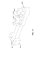
- a third embodiment of the jig designated with the reference numeral 900, comprises all the elements and features of the first and second embodiments of the jig as disclosed herein, mutatis mutandis, with the following differences.
- the jig 900 comprises a substantially rigid strut 920, comprising a spacer member 910 and an arm 922 rigidly attachable to the spacer member 910 at one end 921 of the arm 922 .
- a mounting arrangement 923 is provided, onto which an analog 230 may be mounted at the abutment receiving end thereof in a known and unique spatial relationship with respect thereto. There is thus a unique and fixed spatial relationship between the end 925 and mounting arrangement 923 , and the spacer member 910 .
- Spacer member 910 comprises two longitudinally opposed free ends 911 , 912 thereof, and is reversibly attached to end 921 of arm 922 to form L-shaped strut 920 by an engagement arrangement, including a pair of laterally-spaced pins 915 projecting from end 911 and complementary sockets or apertures 916 formed in the end 921 to receive and retain the pins 915 .
- the mating faces between the ends 921 and 911 and the pins 915 and apertures 916 effectively fix the relative spatial disposition between the arm 922 and the spacer member 910 in six degrees of freedom.
- any other suitable engagement or mounting arrangement may be used to ensure that the arm 922 and spacer member 910 are connected to one another in spatially fixed manner with respect to one another, which is reversible and repeatable.
- the tooth model, 602 ' comprises a base portion 660 ' onto which jig 900 may be mounted via the spacer member 910, wherein end 912 is reversibly attached base portion 660 ' by another engagement arrangement, including a pair of laterally-spaced pins 917 projecting from end 912 and complementary sockets or apertures 918 formed in base portion 660' to receive and retain the pins 917 .
- the mating faces between the end 912 and base portion 660' and the pins 917 and apertures 918 effectively fix the relative spatial disposition between base portion 660' and the spacer member 910 in six degrees of freedom.
- any other suitable engagement or mounting arrangement may be used to ensure that the base portion 660' and spacer member 910 are connected to one another in spatially fixed manner with respect to one another, which is reversible and repeatable.
- the geometry of the spacer member 910 is predefined - for example the spacer member 910 may be a previously manufactured off the shelf item - and the position and orientation of the base portion 660' with respect to the cavity 666' , and the geometry of the arm 922 and relative position between the ends 921 , 922 thereof, are designed such that when the jig 900 is properly engaged with the model 602' , with the spacer member 910 firmly seated in position on the base portion 660' , and the arm 922 firmly engaged to the spacer member 910 , the end 925 automatically brings the analog 230 attached thereto into its correct position with respect to the cavity 666' , and thus the model 602' .
- the model 602' may be manufactured having base portion 660' in a particular standard form and position with respect to the model dentition 601' (i.e., the parts of the model that have external surfaces representative of the external surfaces of the real teeth), and the form and dimensions of the spacer member 910 can also be standard or chosen from a set of standard sizes/forms.
- the corresponding position and orientation of the base portion 660' can be calculated in step 440 in a relatively straightforward manner. Having already designed the virtual equivalent of the cavity 666' in step 440 , the required position and orientation of the second virtual model representing the analog 230 is also known.
- the relative spatial position between the end 925 (and mounting arrangement 923 ) and the spacer member 910 of the jig 900 is also known, and thus by effectively fixing the end 925 to be in an engagement position, in a virtual sense, with the virtual model of the analog 230 , the corresponding position of the end 912 of the spacer member 910 with respect to the third virtual model is automatically fixed.
- the shape and position of the virtual equivalent of the arm 922 may be readily defined in the third virtual model, being essentially such as to position the virtual model of the analog in the desired spatial disposition with respect to the corresponding position of the end 912 of the spacer member 910 .
- a suitable machining or other material removal operation may be used for manufacturing the arm 922 from a blank, or alternatively the arm 922 may be formed via a rapid prototyping process.
- Mounting arrangement 923 may be integrally formed with the arm 922 , or alternatively may be formed separately and fixed in place at end 925 is the required spatial disposition with respect thereto.
- the dental model may be used for designing and fitting a prosthesis to the analog 230 , which facilitates the ultimate engagement of the prosthesis with the respective implant in the intra-oral cavity of the patient.
- the base portion 660' and the engagement arrangement thereof, in particular the apertures 918 may be designed in the first place also to be compatible with the mounting arrangement of an articulator, which for example may have mounting pins similar to pins 917 .
- a physical model of the patient's opposed dentition in occlusal relationship with the teeth that are represented by model 602' can also be mounted to the articulator, and thus the user can study the occlusal relationship between the two dental models and the effect of the prosthesis.
- the jig according to the present invention may be used with any suitable cavity, which can be of any suitable shape and is larger than the part of the physical analog that it is desired to embed therein, such as to provide a clearance gap between this part of the analog and the cavity.
- the term "cavity" refers to any well, bore, slot or any other receiving volume created in the physical model in which the analog may be accommodated and cemented in place by means of suitable filler material applied to the clearance gap.
- a physical model 980 of the patient's dentition of the opposed dental arch in occlusal relationship with the teeth 601' can be mounted to the spacer member 910 once the arm 922 is removed, and thus the user can study the occlusal relationship between the two dental models and how this is affected by the prosthesis that is mounted to the implant (not shown).
- the form and size of the spacer member 910 , as well as the size and form of the engaging base portion 982 of the dental model 980 are such that when the dental models 982 , 602' are mounted to one another via the spacer member 910 , the corresponding teeth models 981 , 601' are in occlusal relationship.
- a system and method according to a fourth embodiment of the invention comprises all the elements and features of the first through third embodiments as disclosed herein, mutatis mutandis, with the following differences.
- the analog is not assembled into the manufactured physical model, but rather the physical model is integrally manufactured with the analog.
- steps 410 to 440 can be substantially identical to the same steps as disclosed for the first embodiment, mutatis mutandis.
- the manufacturing step 450 comprises embedding the analog 230 in a blank 800 of material in a position and orientation that enables the physical model 606 to be machined from the blank 800 such that at the end of the machining or material removal process, the analog 230 will effectively end up in the desired position vis-à-vis the finished model 606 .
- the starting point of the blank 800 may be such that the analog is effectively fully submerged in the blank 800 , in a known position and orientation with respect to a reference plane P of the blank.
- the analog 230 may be held in a particular, known, position and orientation with respect to a plate 820 via a rigid, though optionally removable jig 840 .
- Plate 820 defines plane P at the upper surface 821 thereof.
- the blank 800 can be formed by casting a suitable machinable material over plate 820 (contained by a suitable surrounding wall, not shown) up to a level above the analog 230 sufficient to ensure that the heights of all parts of the eventual model 606 are below this level.
- step 440 may further comprise the step of constructing a virtual blank surrounding the third virtual model, and comprising a reference plane corresponding to plane P in the corresponding position with respect to the relative position of the second virtual model re the third virtual model, to that of the relative position and orientation between the analog 230 and plate 820 , as provided by the jig 840 . This facilitates design and manufacture of the blank 800 .
- plate 820 may optionally be configured for being mountable with respect to the manufacturing system 280 in a predetermined and unique manner relative to the coordinate system C thereof, for example, and thus when mounted for machining in the manufacturing system 280 the position and orientation of the analog 230 with respect to the plate 820 , and thus the manufacturing system's coordinate system is automatically fixed, thereby automatically aligning the blank in the manufacturing system 280 , which can then mill or otherwise machine the blank 800 to produce the model 606 therefrom.
- the computer system 260 in which the virtual models are created and manipulated according to any of the embodiments of the invention does not necessarily need to be located in the same geographical location as the scanner 250 and patient.
- the dental clinic may instead or additionally be linked to one or more dental labs, and possibly also to a dental service center via a communication means or network such as for example the Internet or other suitable communications medium such as an intranet, local access network, public switched telephone network, cable network, satellite communication system, and the like.
- the communication means may include postal or courier services, the data being communicated via a transportable medium such as an optical disc, magnetic disc and so on.
- the physical dental model, and other dental procedures not carried out on the actual patient may be carried out by the dental lab which receives the required data generated by the method 400 via the communications means.
- the dental service center may be used for manufacturing dental hardware that requires a very high degree of precision, for example inner surfaces of prostheses that are required to match external surfaces of copings, and possibly also the copings themselves.
Priority Applications (3)
| Application Number | Priority Date | Filing Date | Title |
|---|---|---|---|
| ES09180197.7T ES2639571T3 (es) | 2009-12-21 | 2009-12-21 | Uso de un posicionador con análogos y modelos dentales |
| EP09180197.7A EP2335640B1 (fr) | 2009-12-21 | 2009-12-21 | L'usage d'un dispositif de positionnement avec analogues et modèles dentaires |
| EP16164374.7A EP3058892A1 (fr) | 2009-12-21 | 2009-12-21 | Dispositif de positionnement pour l'usage avec analogues et modèles dentaires |
Applications Claiming Priority (1)
| Application Number | Priority Date | Filing Date | Title |
|---|---|---|---|
| EP09180197.7A EP2335640B1 (fr) | 2009-12-21 | 2009-12-21 | L'usage d'un dispositif de positionnement avec analogues et modèles dentaires |
Related Child Applications (2)
| Application Number | Title | Priority Date | Filing Date |
|---|---|---|---|
| EP16164374.7A Division-Into EP3058892A1 (fr) | 2009-12-21 | 2009-12-21 | Dispositif de positionnement pour l'usage avec analogues et modèles dentaires |
| EP16164374.7A Division EP3058892A1 (fr) | 2009-12-21 | 2009-12-21 | Dispositif de positionnement pour l'usage avec analogues et modèles dentaires |
Publications (2)
| Publication Number | Publication Date |
|---|---|
| EP2335640A1 true EP2335640A1 (fr) | 2011-06-22 |
| EP2335640B1 EP2335640B1 (fr) | 2017-07-19 |
Family
ID=42167723
Family Applications (2)
| Application Number | Title | Priority Date | Filing Date |
|---|---|---|---|
| EP16164374.7A Withdrawn EP3058892A1 (fr) | 2009-12-21 | 2009-12-21 | Dispositif de positionnement pour l'usage avec analogues et modèles dentaires |
| EP09180197.7A Active EP2335640B1 (fr) | 2009-12-21 | 2009-12-21 | L'usage d'un dispositif de positionnement avec analogues et modèles dentaires |
Family Applications Before (1)
| Application Number | Title | Priority Date | Filing Date |
|---|---|---|---|
| EP16164374.7A Withdrawn EP3058892A1 (fr) | 2009-12-21 | 2009-12-21 | Dispositif de positionnement pour l'usage avec analogues et modèles dentaires |
Country Status (2)
| Country | Link |
|---|---|
| EP (2) | EP3058892A1 (fr) |
| ES (1) | ES2639571T3 (fr) |
Cited By (1)
| Publication number | Priority date | Publication date | Assignee | Title |
|---|---|---|---|---|
| US8905757B2 (en) | 2012-12-03 | 2014-12-09 | E. Kats Enterprises Ltd. | Method and apparatus for measuring a location and orientation of a plurality of implants |
Families Citing this family (1)
| Publication number | Priority date | Publication date | Assignee | Title |
|---|---|---|---|---|
| EP4013346A4 (fr) * | 2019-08-12 | 2023-09-13 | Smylio Inc. | Systèmes et procédés pour une intervention de traitement orthodontique |
Citations (7)
| Publication number | Priority date | Publication date | Assignee | Title |
|---|---|---|---|---|
| US4240605A (en) * | 1979-09-17 | 1980-12-23 | Pennwalt Corporation | Jig assembly for preparing dental impressions for casting |
| WO2000008415A1 (fr) | 1998-08-05 | 2000-02-17 | Cadent Ltd. | Imagerie d'une structure tridimensionnelle par focalisation confocale d'un reseau de faisceaux lumineux |
| US6358052B1 (en) | 1999-07-15 | 2002-03-19 | L. Paul Lustig | Dental implant system and method for effecting a dental restoration using the same |
| DE20309508U1 (de) * | 2003-06-18 | 2003-09-11 | Kiefer Inge H | Abstützung für zahntechnische Modelle |
| US20060001739A1 (en) | 2004-06-17 | 2006-01-05 | Noam Babayoff | Method and apparatus for colour imaging a three-dimensional structure |
| US20060183078A1 (en) | 2005-02-11 | 2006-08-17 | Niznick Gerald A | One-piece, screw-receiving, externally-threaded endosseous dental implants and related transfer components, comfort caps and abutments |
| US20080032262A1 (en) | 2006-08-01 | 2008-02-07 | Vitali Bondar | Dental implant system and method thereof |
Family Cites Families (2)
| Publication number | Priority date | Publication date | Assignee | Title |
|---|---|---|---|---|
| EP1172072A1 (fr) * | 2000-07-14 | 2002-01-16 | ISP Individual-System Prothetik AG | Dispositif de support pour des modèles d'articulation anatomiques |
| US20040126731A1 (en) * | 2002-10-08 | 2004-07-01 | Tbl Partnership | Clutch transfer device |
-
2009
- 2009-12-21 ES ES09180197.7T patent/ES2639571T3/es active Active
- 2009-12-21 EP EP16164374.7A patent/EP3058892A1/fr not_active Withdrawn
- 2009-12-21 EP EP09180197.7A patent/EP2335640B1/fr active Active
Patent Citations (7)
| Publication number | Priority date | Publication date | Assignee | Title |
|---|---|---|---|---|
| US4240605A (en) * | 1979-09-17 | 1980-12-23 | Pennwalt Corporation | Jig assembly for preparing dental impressions for casting |
| WO2000008415A1 (fr) | 1998-08-05 | 2000-02-17 | Cadent Ltd. | Imagerie d'une structure tridimensionnelle par focalisation confocale d'un reseau de faisceaux lumineux |
| US6358052B1 (en) | 1999-07-15 | 2002-03-19 | L. Paul Lustig | Dental implant system and method for effecting a dental restoration using the same |
| DE20309508U1 (de) * | 2003-06-18 | 2003-09-11 | Kiefer Inge H | Abstützung für zahntechnische Modelle |
| US20060001739A1 (en) | 2004-06-17 | 2006-01-05 | Noam Babayoff | Method and apparatus for colour imaging a three-dimensional structure |
| US20060183078A1 (en) | 2005-02-11 | 2006-08-17 | Niznick Gerald A | One-piece, screw-receiving, externally-threaded endosseous dental implants and related transfer components, comfort caps and abutments |
| US20080032262A1 (en) | 2006-08-01 | 2008-02-07 | Vitali Bondar | Dental implant system and method thereof |
Cited By (1)
| Publication number | Priority date | Publication date | Assignee | Title |
|---|---|---|---|---|
| US8905757B2 (en) | 2012-12-03 | 2014-12-09 | E. Kats Enterprises Ltd. | Method and apparatus for measuring a location and orientation of a plurality of implants |
Also Published As
| Publication number | Publication date |
|---|---|
| EP2335640B1 (fr) | 2017-07-19 |
| EP3058892A1 (fr) | 2016-08-24 |
| ES2639571T3 (es) | 2017-10-27 |
Similar Documents
| Publication | Publication Date | Title |
|---|---|---|
| US11654004B2 (en) | Methods, systems and accessories useful for procedures relating to dental implants | |
| US10675130B2 (en) | Virtual and physical dental models of dental surfaces and analog socket structure of a dental implant and related procedures | |
| EP1043960B1 (fr) | Methode de realisation d'une superstructure d'implant dentaire | |
| US6382975B1 (en) | Manufacturing a dental implant drill guide and a dental implant superstructure | |
| EP2958514B1 (fr) | Aide pour implant dentaire précalibré | |
| US20120308963A1 (en) | Dental diagnosic and dental restoration methods, systems, apparatuses, and devices | |
| US20070281279A1 (en) | Custom impression transfer coping | |
| KR101707910B1 (ko) | 치과 임플란트 관련 시술에 유용한 방법, 시스템 및 액세서리 | |
| EP2335640B1 (fr) | L'usage d'un dispositif de positionnement avec analogues et modèles dentaires | |
| TWI623302B (zh) | 用於製造一實體牙模之方法及該方法所製之實體牙模 | |
| KR20190069600A (ko) | 치아 보철물 | |
| TWI632895B (zh) | 用於牙科植入物之夾具及包含其之套組 | |
| EP2858590A1 (fr) | Procédé et kit pour fabriquer des gabarits chirurgicaux pour implantation dentaire | |
| CA2549434A1 (fr) | Chape personnalisee de transfert d'empreinte |
Legal Events
| Date | Code | Title | Description |
|---|---|---|---|
| PUAI | Public reference made under article 153(3) epc to a published international application that has entered the european phase |
Free format text: ORIGINAL CODE: 0009012 |
|
| AK | Designated contracting states |
Kind code of ref document: A1 Designated state(s): AT BE BG CH CY CZ DE DK EE ES FI FR GB GR HR HU IE IS IT LI LT LU LV MC MK MT NL NO PL PT RO SE SI SK SM TR |
|
| AX | Request for extension of the european patent |
Extension state: AL BA RS |
|
| 17P | Request for examination filed |
Effective date: 20111221 |
|
| RAP1 | Party data changed (applicant data changed or rights of an application transferred) |
Owner name: ALIGN TECHNOLOGY, INC. |
|
| 17Q | First examination report despatched |
Effective date: 20150820 |
|
| GRAP | Despatch of communication of intention to grant a patent |
Free format text: ORIGINAL CODE: EPIDOSNIGR1 |
|
| STAA | Information on the status of an ep patent application or granted ep patent |
Free format text: STATUS: GRANT OF PATENT IS INTENDED |
|
| INTG | Intention to grant announced |
Effective date: 20170213 |
|
| GRAS | Grant fee paid |
Free format text: ORIGINAL CODE: EPIDOSNIGR3 |
|
| GRAA | (expected) grant |
Free format text: ORIGINAL CODE: 0009210 |
|
| STAA | Information on the status of an ep patent application or granted ep patent |
Free format text: STATUS: THE PATENT HAS BEEN GRANTED |
|
| AK | Designated contracting states |
Kind code of ref document: B1 Designated state(s): AT BE BG CH CY CZ DE DK EE ES FI FR GB GR HR HU IE IS IT LI LT LU LV MC MK MT NL NO PL PT RO SE SI SK SM TR |
|
| REG | Reference to a national code |
Ref country code: GB Ref legal event code: FG4D |
|
| REG | Reference to a national code |
Ref country code: CH Ref legal event code: EP |
|
| REG | Reference to a national code |
Ref country code: IE Ref legal event code: FG4D |
|
| REG | Reference to a national code |
Ref country code: AT Ref legal event code: REF Ref document number: 909619 Country of ref document: AT Kind code of ref document: T Effective date: 20170815 |
|
| REG | Reference to a national code |
Ref country code: DE Ref legal event code: R096 Ref document number: 602009047185 Country of ref document: DE |
|
| REG | Reference to a national code |
Ref country code: ES Ref legal event code: FG2A Ref document number: 2639571 Country of ref document: ES Kind code of ref document: T3 Effective date: 20171027 |
|
| REG | Reference to a national code |
Ref country code: FR Ref legal event code: PLFP Year of fee payment: 9 |
|
| REG | Reference to a national code |
Ref country code: NL Ref legal event code: MP Effective date: 20170719 |
|
| REG | Reference to a national code |
Ref country code: LT Ref legal event code: MG4D |
|
| REG | Reference to a national code |
Ref country code: AT Ref legal event code: MK05 Ref document number: 909619 Country of ref document: AT Kind code of ref document: T Effective date: 20170719 |
|
| RAP2 | Party data changed (patent owner data changed or rights of a patent transferred) |
Owner name: ALIGN TECHNOLOGY, INC. |
|
| PG25 | Lapsed in a contracting state [announced via postgrant information from national office to epo] |
Ref country code: NL Free format text: LAPSE BECAUSE OF FAILURE TO SUBMIT A TRANSLATION OF THE DESCRIPTION OR TO PAY THE FEE WITHIN THE PRESCRIBED TIME-LIMIT Effective date: 20170719 Ref country code: HR Free format text: LAPSE BECAUSE OF FAILURE TO SUBMIT A TRANSLATION OF THE DESCRIPTION OR TO PAY THE FEE WITHIN THE PRESCRIBED TIME-LIMIT Effective date: 20170719 Ref country code: LT Free format text: LAPSE BECAUSE OF FAILURE TO SUBMIT A TRANSLATION OF THE DESCRIPTION OR TO PAY THE FEE WITHIN THE PRESCRIBED TIME-LIMIT Effective date: 20170719 Ref country code: SE Free format text: LAPSE BECAUSE OF FAILURE TO SUBMIT A TRANSLATION OF THE DESCRIPTION OR TO PAY THE FEE WITHIN THE PRESCRIBED TIME-LIMIT Effective date: 20170719 Ref country code: AT Free format text: LAPSE BECAUSE OF FAILURE TO SUBMIT A TRANSLATION OF THE DESCRIPTION OR TO PAY THE FEE WITHIN THE PRESCRIBED TIME-LIMIT Effective date: 20170719 Ref country code: FI Free format text: LAPSE BECAUSE OF FAILURE TO SUBMIT A TRANSLATION OF THE DESCRIPTION OR TO PAY THE FEE WITHIN THE PRESCRIBED TIME-LIMIT Effective date: 20170719 Ref country code: NO Free format text: LAPSE BECAUSE OF FAILURE TO SUBMIT A TRANSLATION OF THE DESCRIPTION OR TO PAY THE FEE WITHIN THE PRESCRIBED TIME-LIMIT Effective date: 20171019 |
|
| PG25 | Lapsed in a contracting state [announced via postgrant information from national office to epo] |
Ref country code: GR Free format text: LAPSE BECAUSE OF FAILURE TO SUBMIT A TRANSLATION OF THE DESCRIPTION OR TO PAY THE FEE WITHIN THE PRESCRIBED TIME-LIMIT Effective date: 20171020 Ref country code: LV Free format text: LAPSE BECAUSE OF FAILURE TO SUBMIT A TRANSLATION OF THE DESCRIPTION OR TO PAY THE FEE WITHIN THE PRESCRIBED TIME-LIMIT Effective date: 20170719 Ref country code: BG Free format text: LAPSE BECAUSE OF FAILURE TO SUBMIT A TRANSLATION OF THE DESCRIPTION OR TO PAY THE FEE WITHIN THE PRESCRIBED TIME-LIMIT Effective date: 20171019 Ref country code: IS Free format text: LAPSE BECAUSE OF FAILURE TO SUBMIT A TRANSLATION OF THE DESCRIPTION OR TO PAY THE FEE WITHIN THE PRESCRIBED TIME-LIMIT Effective date: 20171119 Ref country code: PL Free format text: LAPSE BECAUSE OF FAILURE TO SUBMIT A TRANSLATION OF THE DESCRIPTION OR TO PAY THE FEE WITHIN THE PRESCRIBED TIME-LIMIT Effective date: 20170719 |
|
| REG | Reference to a national code |
Ref country code: DE Ref legal event code: R097 Ref document number: 602009047185 Country of ref document: DE |
|
| PG25 | Lapsed in a contracting state [announced via postgrant information from national office to epo] |
Ref country code: DK Free format text: LAPSE BECAUSE OF FAILURE TO SUBMIT A TRANSLATION OF THE DESCRIPTION OR TO PAY THE FEE WITHIN THE PRESCRIBED TIME-LIMIT Effective date: 20170719 Ref country code: CZ Free format text: LAPSE BECAUSE OF FAILURE TO SUBMIT A TRANSLATION OF THE DESCRIPTION OR TO PAY THE FEE WITHIN THE PRESCRIBED TIME-LIMIT Effective date: 20170719 Ref country code: RO Free format text: LAPSE BECAUSE OF FAILURE TO SUBMIT A TRANSLATION OF THE DESCRIPTION OR TO PAY THE FEE WITHIN THE PRESCRIBED TIME-LIMIT Effective date: 20170719 |
|
| PLBE | No opposition filed within time limit |
Free format text: ORIGINAL CODE: 0009261 |
|
| STAA | Information on the status of an ep patent application or granted ep patent |
Free format text: STATUS: NO OPPOSITION FILED WITHIN TIME LIMIT |
|
| PG25 | Lapsed in a contracting state [announced via postgrant information from national office to epo] |
Ref country code: SK Free format text: LAPSE BECAUSE OF FAILURE TO SUBMIT A TRANSLATION OF THE DESCRIPTION OR TO PAY THE FEE WITHIN THE PRESCRIBED TIME-LIMIT Effective date: 20170719 Ref country code: IT Free format text: LAPSE BECAUSE OF FAILURE TO SUBMIT A TRANSLATION OF THE DESCRIPTION OR TO PAY THE FEE WITHIN THE PRESCRIBED TIME-LIMIT Effective date: 20170719 Ref country code: SM Free format text: LAPSE BECAUSE OF FAILURE TO SUBMIT A TRANSLATION OF THE DESCRIPTION OR TO PAY THE FEE WITHIN THE PRESCRIBED TIME-LIMIT Effective date: 20170719 Ref country code: EE Free format text: LAPSE BECAUSE OF FAILURE TO SUBMIT A TRANSLATION OF THE DESCRIPTION OR TO PAY THE FEE WITHIN THE PRESCRIBED TIME-LIMIT Effective date: 20170719 |
|
| 26N | No opposition filed |
Effective date: 20180420 |
|
| REG | Reference to a national code |
Ref country code: CH Ref legal event code: PL |
|
| PG25 | Lapsed in a contracting state [announced via postgrant information from national office to epo] |
Ref country code: SI Free format text: LAPSE BECAUSE OF FAILURE TO SUBMIT A TRANSLATION OF THE DESCRIPTION OR TO PAY THE FEE WITHIN THE PRESCRIBED TIME-LIMIT Effective date: 20170719 |
|
| REG | Reference to a national code |
Ref country code: IE Ref legal event code: MM4A |
|
| PG25 | Lapsed in a contracting state [announced via postgrant information from national office to epo] |
Ref country code: MT Free format text: LAPSE BECAUSE OF NON-PAYMENT OF DUE FEES Effective date: 20171221 Ref country code: LU Free format text: LAPSE BECAUSE OF NON-PAYMENT OF DUE FEES Effective date: 20171221 |
|
| REG | Reference to a national code |
Ref country code: BE Ref legal event code: MM Effective date: 20171231 |
|
| PG25 | Lapsed in a contracting state [announced via postgrant information from national office to epo] |
Ref country code: IE Free format text: LAPSE BECAUSE OF NON-PAYMENT OF DUE FEES Effective date: 20171221 |
|
| PG25 | Lapsed in a contracting state [announced via postgrant information from national office to epo] |
Ref country code: LI Free format text: LAPSE BECAUSE OF NON-PAYMENT OF DUE FEES Effective date: 20171231 Ref country code: BE Free format text: LAPSE BECAUSE OF NON-PAYMENT OF DUE FEES Effective date: 20171231 Ref country code: CH Free format text: LAPSE BECAUSE OF NON-PAYMENT OF DUE FEES Effective date: 20171231 |
|
| PG25 | Lapsed in a contracting state [announced via postgrant information from national office to epo] |
Ref country code: MC Free format text: LAPSE BECAUSE OF FAILURE TO SUBMIT A TRANSLATION OF THE DESCRIPTION OR TO PAY THE FEE WITHIN THE PRESCRIBED TIME-LIMIT Effective date: 20170719 Ref country code: HU Free format text: LAPSE BECAUSE OF FAILURE TO SUBMIT A TRANSLATION OF THE DESCRIPTION OR TO PAY THE FEE WITHIN THE PRESCRIBED TIME-LIMIT; INVALID AB INITIO Effective date: 20091221 |
|
| PG25 | Lapsed in a contracting state [announced via postgrant information from national office to epo] |
Ref country code: CY Free format text: LAPSE BECAUSE OF NON-PAYMENT OF DUE FEES Effective date: 20170719 |
|
| PG25 | Lapsed in a contracting state [announced via postgrant information from national office to epo] |
Ref country code: MK Free format text: LAPSE BECAUSE OF FAILURE TO SUBMIT A TRANSLATION OF THE DESCRIPTION OR TO PAY THE FEE WITHIN THE PRESCRIBED TIME-LIMIT Effective date: 20170719 |
|
| PG25 | Lapsed in a contracting state [announced via postgrant information from national office to epo] |
Ref country code: TR Free format text: LAPSE BECAUSE OF FAILURE TO SUBMIT A TRANSLATION OF THE DESCRIPTION OR TO PAY THE FEE WITHIN THE PRESCRIBED TIME-LIMIT Effective date: 20170719 |
|
| PG25 | Lapsed in a contracting state [announced via postgrant information from national office to epo] |
Ref country code: PT Free format text: LAPSE BECAUSE OF FAILURE TO SUBMIT A TRANSLATION OF THE DESCRIPTION OR TO PAY THE FEE WITHIN THE PRESCRIBED TIME-LIMIT Effective date: 20170719 |
|
| PGFP | Annual fee paid to national office [announced via postgrant information from national office to epo] |
Ref country code: ES Payment date: 20230110 Year of fee payment: 14 |
|
| P01 | Opt-out of the competence of the unified patent court (upc) registered |
Effective date: 20230523 |
|
| PGFP | Annual fee paid to national office [announced via postgrant information from national office to epo] |
Ref country code: GB Payment date: 20231102 Year of fee payment: 15 |
|
| PGFP | Annual fee paid to national office [announced via postgrant information from national office to epo] |
Ref country code: FR Payment date: 20231108 Year of fee payment: 15 Ref country code: DE Payment date: 20231024 Year of fee payment: 15 |
|
| PGFP | Annual fee paid to national office [announced via postgrant information from national office to epo] |
Ref country code: ES Payment date: 20240118 Year of fee payment: 15 |