EP2335326B1 - Electrical contact, set of electrical contact, product and assembly comprising such an electrical contact, its method of manufacture and method of electrical connection - Google Patents
Electrical contact, set of electrical contact, product and assembly comprising such an electrical contact, its method of manufacture and method of electrical connection Download PDFInfo
- Publication number
- EP2335326B1 EP2335326B1 EP08875919A EP08875919A EP2335326B1 EP 2335326 B1 EP2335326 B1 EP 2335326B1 EP 08875919 A EP08875919 A EP 08875919A EP 08875919 A EP08875919 A EP 08875919A EP 2335326 B1 EP2335326 B1 EP 2335326B1
- Authority
- EP
- European Patent Office
- Prior art keywords
- contact
- electrical
- electrical contact
- cover
- complementary
- Prior art date
- Legal status (The legal status is an assumption and is not a legal conclusion. Google has not performed a legal analysis and makes no representation as to the accuracy of the status listed.)
- Active
Links
Images




Classifications
-
- H—ELECTRICITY
- H01—ELECTRIC ELEMENTS
- H01R—ELECTRICALLY-CONDUCTIVE CONNECTIONS; STRUCTURAL ASSOCIATIONS OF A PLURALITY OF MUTUALLY-INSULATED ELECTRICAL CONNECTING ELEMENTS; COUPLING DEVICES; CURRENT COLLECTORS
- H01R4/00—Electrically-conductive connections between two or more conductive members in direct contact, i.e. touching one another; Means for effecting or maintaining such contact; Electrically-conductive connections having two or more spaced connecting locations for conductors and using contact members penetrating insulation
- H01R4/10—Electrically-conductive connections between two or more conductive members in direct contact, i.e. touching one another; Means for effecting or maintaining such contact; Electrically-conductive connections having two or more spaced connecting locations for conductors and using contact members penetrating insulation effected solely by twisting, wrapping, bending, crimping, or other permanent deformation
- H01R4/18—Electrically-conductive connections between two or more conductive members in direct contact, i.e. touching one another; Means for effecting or maintaining such contact; Electrically-conductive connections having two or more spaced connecting locations for conductors and using contact members penetrating insulation effected solely by twisting, wrapping, bending, crimping, or other permanent deformation by crimping
- H01R4/183—Electrically-conductive connections between two or more conductive members in direct contact, i.e. touching one another; Means for effecting or maintaining such contact; Electrically-conductive connections having two or more spaced connecting locations for conductors and using contact members penetrating insulation effected solely by twisting, wrapping, bending, crimping, or other permanent deformation by crimping for cylindrical elongated bodies, e.g. cables having circular cross-section
- H01R4/184—Electrically-conductive connections between two or more conductive members in direct contact, i.e. touching one another; Means for effecting or maintaining such contact; Electrically-conductive connections having two or more spaced connecting locations for conductors and using contact members penetrating insulation effected solely by twisting, wrapping, bending, crimping, or other permanent deformation by crimping for cylindrical elongated bodies, e.g. cables having circular cross-section comprising a U-shaped wire-receiving portion
-
- H—ELECTRICITY
- H01—ELECTRIC ELEMENTS
- H01R—ELECTRICALLY-CONDUCTIVE CONNECTIONS; STRUCTURAL ASSOCIATIONS OF A PLURALITY OF MUTUALLY-INSULATED ELECTRICAL CONNECTING ELEMENTS; COUPLING DEVICES; CURRENT COLLECTORS
- H01R13/00—Details of coupling devices of the kinds covered by groups H01R12/70 or H01R24/00 - H01R33/00
- H01R13/02—Contact members
- H01R13/15—Pins, blades or sockets having separate spring member for producing or increasing contact pressure
- H01R13/187—Pins, blades or sockets having separate spring member for producing or increasing contact pressure with spring member in the socket
-
- H—ELECTRICITY
- H01—ELECTRIC ELEMENTS
- H01R—ELECTRICALLY-CONDUCTIVE CONNECTIONS; STRUCTURAL ASSOCIATIONS OF A PLURALITY OF MUTUALLY-INSULATED ELECTRICAL CONNECTING ELEMENTS; COUPLING DEVICES; CURRENT COLLECTORS
- H01R13/00—Details of coupling devices of the kinds covered by groups H01R12/70 or H01R24/00 - H01R33/00
- H01R13/64—Means for preventing incorrect coupling
-
- H—ELECTRICITY
- H01—ELECTRIC ELEMENTS
- H01R—ELECTRICALLY-CONDUCTIVE CONNECTIONS; STRUCTURAL ASSOCIATIONS OF A PLURALITY OF MUTUALLY-INSULATED ELECTRICAL CONNECTING ELEMENTS; COUPLING DEVICES; CURRENT COLLECTORS
- H01R13/00—Details of coupling devices of the kinds covered by groups H01R12/70 or H01R24/00 - H01R33/00
- H01R13/02—Contact members
- H01R13/10—Sockets for co-operation with pins or blades
- H01R13/11—Resilient sockets
- H01R13/111—Resilient sockets co-operating with pins having a circular transverse section
-
- H—ELECTRICITY
- H01—ELECTRIC ELEMENTS
- H01R—ELECTRICALLY-CONDUCTIVE CONNECTIONS; STRUCTURAL ASSOCIATIONS OF A PLURALITY OF MUTUALLY-INSULATED ELECTRICAL CONNECTING ELEMENTS; COUPLING DEVICES; CURRENT COLLECTORS
- H01R2201/00—Connectors or connections adapted for particular applications
- H01R2201/26—Connectors or connections adapted for particular applications for vehicles
Definitions
- the instant invention relates to electrical contacts, sets of electrical contacts, for instance for connector used in motorized vehicles, products and assemblies comprising such electrical contacts, their methods of manufacture and methods of electrical connection.
- Electrical connectors are used for connecting electrical appliances together.
- electrically powered cars or partly electrically powered cars, such as so-called “hybrid” cars
- hybrid electrically powered cars
- This requires new generations of connectors for supplying electrical motors with higher voltages than those required for appliances such as window-lifters, radio, etc.
- a certain class of electrical connectors usable in this context is made as an electrically insulating housing comprising three ways. In each of these ways, an electrical contact which is crimped on a cable is inserted.
- An example of electrical contact is describes for instance in DE 1 02 11 634 .
- This contact comprises a wire crimping portion crimped on an electrical wire and a power contact portion having a cylindrical shape for accommodating a complementary contact.
- the power contact portion is provided with a barrel with a plurality of contact blades elastically curved toward the central and longitudinal axis of the cylindrical power contact portion.
- this contact is integrally incorporated in an insulating plastic housing comprising two separate top and bottom parts mechanically locked to one another.
- the instant invention has notably for object to make easier the manufacturing of such a contact.
- the electrical contact is provided with a plurality of spring legs integral with the power contact portion. This ensures direct paths for the current as well as a large surface of electrical connection between the contact and its mating contact. Further, a cover will protect the spring legs against any damage that might occur during handling, transportation or storage occurring between the manufacturing of the contact, and its insertion in the housing. Thought, the number of parts of the contact is reduced with regard to the contact disclosed in DE 1 02 11 634 , making the manufacturing process easier.
- Such contacts could alternatively be used for other applications than the electrical automotive application.
- Fig. 1 schematically shows an apparatus 1 for the manufacture of an electrical contact.
- the apparatus comprises, for example, a crimping portion forming station 2, a first assembly station 3, a power contact portion forming station 4 and a second assembly station 5.
- the crimping portion forming station 2, the first assembly station 3 and the second assembly station 5 are for example disposed in line and adapted to perform series of operations continuously on a blank 6 of material.
- the blank 6 is for example provided in a shape of a continuous strip 7 to which are connected, through respective connecting portions 8, pieces 9 to be formed.
- These pieces 9 are electrically conducting, for example metallic or of a metallic alloy such as a copper alloy.
- the blank 6 as represented on Fig. 1 was previously obtained by forming from a plane conductive thin plate.
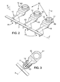
- the crimping portion forming station 2 needs not to be described in more details. It is sufficient to explain that it is suitable for forming, from each piece 9, the first piece 10 as shown on Fig. 2 and 3 .
- This first piece 10 comprises a wire crimping portion 11 which is directly connected to the strip 7 through the connection portion 8, and a retention portion 12 which will be described in detail.
- the wire crimping portion 11 comprises a partly cylindrical barrel 13 of axis X, from which extend upwardly and outwardly on Fig. 3 two crimping wings 14, which, at this stage of the manufactured process, are still in the uncrimped configuration.
- the barrel 13 and the crimping wings 14 together define a receiving space 15 for receiving the end of an electrical wire extending along a first longitudinal direction identical to the axis X.
- the retention portion 12 comprises a flat platform or flange 60 from which a mechanical retention feature 16 projects upwardly.
- it is shaped as a ring 16 extending circumferentially about a second longitudinal axis Y.
- the axis Y is orthogonal to a plane defined by the first longitudinal direction X and the direction Z of extension of the strip 7.
- the present invention could be used also for other orientations of the second longitudinal axis Y, in particular when the axis Y is parallel to the axis X.
- the platform 60 also comprises a second mechanical retention feature 17, which is, in the present example, performed as a tab 17 at the end of the platform 60 opposite to the end of the piece 10 connected to the strip 7.
- An intermediate portion 18 is provided between the wire crimping portion 11 and the retention portion 12 for connecting these two portions together.
- This intermediate portion 18 can for example be designed as a stepped portion for placing the ring 16 in a plane above the wire crimping portion 11. Yet, other geometries are possible, which will depend on the configuration of the electrical connector, and the available space.
- the product of Fig. 2 and 3 exits the crimping portion forming station 2 to enter a first assembly station 3.
- This station also comprises a dispenser 19 (see Fig. 1 ) of covers 20.
- a dispenser 19 see Fig. 1
- One embodiment of a cover is shown on Figs. 4a and 4b .
- the first assembly station 3 is adapted to assemble a cover 20 to each of the first pieces 10 as obtained from the crimping portion forming station and as shown on Figs. 2 and 3 .
- the covers 20 are made of an electrically insulating material such as, for example, a suitable plastic and might have been moulded to the shape shown on Figs. 4a and 4b .
- Each cover 20 comprises a connecting portion 21 which is for example designed as a platform extending mainly in the reference plane P formed by the axis X and Z, and a protecting portion 22 comprising a cylindrical body 23 and a collar 24.
- the top end of the cylindrical body is connected to the bottom face of the platform 21, whereas the collar 24 is formed at the bottom end of the body 23.
- the cylindrical body extends along the longitudinal axis Y and has an external wall 23a and an internal wall 23b which defines an inside space 25.
- the rear end of the platform 21 comprises two legs 26 symmetrical with respect to the X axis and which define, between them, an insertion opening 27.
- the two legs 26 are connected together by a bridge 28 which extends over the insertion opening 27.
- the insertion opening 27 comprises a first narrow space 29a and a broad space 29b closer to the axis of the cylindrical body, so that faces 30, which face frontward, define mechanical locking features for engagement with complementary mechanical locking feature of the connector (to be explained later in relation to Fig. 10 ).
- the bridge 28 comprises a downward facing face 31 which defines a mechanical locking feature with the first piece 10 as will be explained below in relation to Fig. 7 .
- the lateral sides 32 of the bridge 28 are provided with specific geometrical features to provide a fool-proofing feature for engagement with a complementary fool-proofing feature of the connector, as will be explained later in relation to Figs. 10 to 11b .
- the cover 20 which has just been described is assembled with the first piece 10 which was described before, by any suitable way.
- the cover is slid along the axis X toward the first piece 10.
- the tab 17 of the retention portion 12 of the first piece 10 is inserted in the space 29a and 29b until the top face of the tab 17 is in contact with the downward facing face 31 of the bridge 28 (see also Fig. 7 ).
- the top face of the platform 21 is thus below the bottom face of the platform 60 of the first piece 10.
- a second blank 106 is introduced into the power contact portion forming station 4 of the apparatus 1.
- the second blank 106 is, for example, of similar design as the blank 6, and comprises a strip 107 extending along a longitudinal direction Z and to which pieces 109 are connected through connecting portions 108.
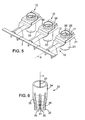
- the power contact portion forming station 4 is suitable to form any of the pieces 109 to a power contact portion 33 such as shown on Fig. 6 .
- Such a power contact portion is for example obtained by forming (stamping) a flat piece 109 and then rolling it to the desired geometry, or by any other suitable way.
- the power contact portion 33 is a cylinder of circular cross-section and comprises a body 34 from which extend a plurality of (for example 8) spring legs 35 sensibly along the longitudinal axis Y.
- the legs 35 extend sensibly downward from the body 34 and inward toward a point of contraflexure 36 from which they are flared outward to their tip.
- the internal face at the point of contraflexure forms a protrusion which projects inside an internal space 61 for receiving a complementary electrical contact therein.
- This complementary electrical contact is preferably of diameter greater than the internal diameter of the power contact portion 33 at the level of the protrusions so that the legs will be resiliently biased in contact with this complementary electrical contact upon its insertion in the internal space.
- a gap 37 may exist between the two longitudinal edges which are brought close to each other during the rolling operation.
- This gap 37 may be closed, for example, by welding, or by any other suitable means.
- the product shown on Fig. 5 , comprising a strip of first pieces 10 of metal carrying a respective cover, is moved from the first assembly station 3 to the second assembly station 5.
- the power contact portion 33 is moved from the power contact portion forming station 4 to the second assembly station 5 to be inserted along the axis Y, from the top, through the ring 16 and the cover 20.
- the external surface of the body 34 biases in electrical contact with the inner face of the ring 16 for electrical communication between these two pieces.
- the spring legs 35 are totally enclosed in the cover 20.
- the body 34 can be welded, if necessary, to the ring 16, or only retained by friction, or any other means. It should be noted that, after the power contact portion 33 has been inserted, it is no longer possible to remove the cover 20 from the electrical contact by sliding along direction X.
- Fig. 8 shows the product which is output from the second assembly station 5 shown schematically on Fig. 1 .
- This product comprises a longitudinal strip 7 to which are connected a plurality of electrical contacts 38.
- the electrical contacts 38 are all identical.
- these electrical contacts 38 have different covers having different colours and/or fool-proofing features (see below Figs. 11a and 11b for more details about this).
- the product shown on Fig. 8 can be provided to a third party for cable assembly and terminal insertion in connectors.
- the individual electrical contacts 38 could be separated from the strip 7 before being provided to a cable assembler or a harness maker.
- the electrical contacts are not necessarily manufactured as two separate conductive pieces. An integral piece comprising a power contact portion and a wire crimping portion might be used.
- Fig. 9 shows a first electrical connector 39 and a second complementary electrical connector 139 to be mated with.
- the first electrical connector 39 is for example made as a dielectric housing 40 defining a plurality of pathways 41a, 41b, 41c which are electrically isolated from one another and extend with a right angle (between axis X and axis Y). Namely, a first end of these openings is provided on a front face of the connector 39, while a second end thereof is provided on its bottom face (not Visible on Fig. 9 ), facing the second connector 139.
- three electrical contacts 38a, 38b, 38c are provided which are manufactured according to the above mentioned process. These three terminals differ from one another by each having a different cover 20a, 20b, 20c.
- the wire crimping portion 11 of each electrical contact is crimped on a respective electrical wire 42 for placing the wire in electrical communication with the electrical contact 38. This can, for example, be performed by folding the crimping wings of the electrical contact on the wire, with a suitable tool comprising a stamping element and an anvil.
- An insulating joint 43 is slid along the sheath of each wire 42 to the position of Fig. 9 and a grid 44 is placed by inserting the wire 42 through the respective openings 45 of the grid.
- the grid has locks 46 for engagement with complementary locks 47 of the first connector 39 to lock the grid onto the first connector 39.
- the joints 43 are circumferentially pressed by internal walls 48 of the first connector 39, and longitudinally pressed between the grid 44 and respective fool-proofing bodies 49 of the respective pathway 41. This will be described in relation to Fig. 10 .
- the electrical contact 38 is mechanically retained in the housing 40 of the first connector by mechanical engagement of the hook 54 with the faces 30 of the cover (see Fig. 4a ).
- the second electrical connector 139 may for example comprise three cylindrical chimneys 50, cylindrical of circular cross-section of diameter greater than the outer diameter of the covers 20.
- An electrical contact 51 is provided for each respective chimney 50.
- These electrical contacts 51 may, for example, comprise a first end 51a which extends in the chimney 50, and an opposite second end 51b for connection to an electrical appliance.
- Fig. 10 shows a sectional view through the pathway 41b. Only the fool-proofing body 49b delimiting this pathway is depicted. As explained above, this body 49 has an aperture 52 on the one hand, for receiving the electrical contact 38, and another aperture 53 in its bottom face for receiving the electrical contact 51 of the complementary connector locking tool 54 is provided on the back face of the body 49b, for example as a hook extending from this back face toward the aperture 52 and having a catching portion 55 born by a resilient arm 56.
- the body 49b has a fool-proofing relief 57 in the top left corner of its profile, which is provided with a given geometry.
- the body 49b is for example made from moulded plastic and may for example be provided with a pigment of a first colour.
- each of the covers 20 has a different fool proofing feature 32 with a specific geometry. Further, although this is not visible on Fig. 11a , each of the covers may incorporate a respective pigment so that they all have different colours. As shown on Fig. 11b , the fool-proofing bodies 49 all have a different fool proofing geometry 57. Further, they all include a different pigment, which provides different colours. For example, the colour of one of the bodies 49 is associated to, preferably is the same as, the colour of a respective cover. Further, the geometries 32 and 57 are chosen so that, among the three covers of Fig. 11a , only one can enter a respective body 49, and is prevented to enter the other bodies. Further, each body can receive only one of the covers. Preferably, the cover which is allowed to be inserted in a respective box is provided with a colour associated to the colour of that box.
- each electrical contact 38 is a right-angled contact in that its two connection axes X and Y are perpendicular to one another.
- the cover 20 is guided into a respective chimney 50 and the complementary electrical contact 51 is placed in electrical contact with the power contact portion 33 of the electrical contact 38.
Landscapes
- Connector Housings Or Holding Contact Members (AREA)
- Manufacturing Of Electrical Connectors (AREA)
- Connections Effected By Soldering, Adhesion, Or Permanent Deformation (AREA)
Abstract
Description
- The instant invention relates to electrical contacts, sets of electrical contacts, for instance for connector used in motorized vehicles, products and assemblies comprising such electrical contacts, their methods of manufacture and methods of electrical connection.
- Electrical connectors are used for connecting electrical appliances together. For example, in the automotive industry, electrically powered cars (or partly electrically powered cars, such as so-called "hybrid" cars) are emerging as an interesting alternative to the fuel-only vehicles. This requires new generations of connectors for supplying electrical motors with higher voltages than those required for appliances such as window-lifters, radio, etc...).
- A certain class of electrical connectors usable in this context is made as an electrically insulating housing comprising three ways. In each of these ways, an electrical contact which is crimped on a cable is inserted.
- An example of electrical contact is describes for instance in
DE 1 02 11 634 . This contact comprises a wire crimping portion crimped on an electrical wire and a power contact portion having a cylindrical shape for accommodating a complementary contact. The power contact portion is provided with a barrel with a plurality of contact blades elastically curved toward the central and longitudinal axis of the cylindrical power contact portion. - After its crimping on the wire, this contact is integrally incorporated in an insulating plastic housing comprising two separate top and bottom parts mechanically locked to one another.
- The instant invention has notably for object to make easier the manufacturing of such a contact.
- Document
US-A-566 7 413 discloses a contact according to the preamble of claim 1. - To this aim, it is provided an electrical contact according to claim 1.
- With these features, the electrical contact is provided with a plurality of spring legs integral with the power contact portion. This ensures direct paths for the current as well as a large surface of electrical connection between the contact and its mating contact. Further, a cover will protect the spring legs against any damage that might occur during handling, transportation or storage occurring between the manufacturing of the contact, and its insertion in the housing. Thought, the number of parts of the contact is reduced with regard to the contact disclosed in
DE 1 02 11 634 , making the manufacturing process easier. - In some embodiments, one might also use one or more of the features as defined in the dependent claims.
- Such contacts could alternatively be used for other applications than the electrical automotive application.
- Other characteristics and advantages of the invention will readily appear from the following description of one of its embodiments, provided as a non-limitative example, and of the accompanying drawings.
- On the drawings:
-
Fig. 1 is a schematic representation of a manufacturing apparatus, -
Fig. 2 is a perspective view of a product obtained at the output of the crimping portion forming station of the apparatus ofFig. 1 , -
Fig. 3 is another partial perspective of the product ofFig. 2 , -
Fig. 4a is a perspective view with roughly the same orientation asFig. 2 of a cover according to a first embodiment, -
Fig. 4b is another perspective view of the cover ofFig. 4a , -
Fig. 5 is a perspective view of the product output from a first assembly station of the apparatus ofFig. 1 , -
Fig. 6 is a perspective view of a product output from a power contact portion forming station of the apparatus ofFig. 1 , -
Fig. 7 is a partial sectional view of an electrical contact obtained from the apparatus ofFig. 1 , taken along line VII-VII ofFig. 8 , -
Fig. 8 is a perspective view of a product output from the apparatus ofFig. 1 , -
Fig. 9 is an exploded view of an electrical connector assembly incorporating electrical contacts, -
Fig. 10 is a sectional view along line X-X onFig. 9 of a fool-proofing body of an electrical connector of the assembly ofFig. 9 , -
Fig. 11a is a rear view of the three covers used in the connector ofFig. 9 , -
Fig. 11b is a schematic cross section of the three fool-proofing bodies of the connector ofFig. 9 , and -
Fig. 12 is a sectional view along line X-X onFig. 9 , of the partly assembled electrical connector assembly. - On the different figures, the same reference signs designate like or similar elements.
-
Fig. 1 schematically shows an apparatus 1 for the manufacture of an electrical contact. The apparatus comprises, for example, a crimpingportion forming station 2, afirst assembly station 3, a power contact portion forming station 4 and asecond assembly station 5. The crimpingportion forming station 2, thefirst assembly station 3 and thesecond assembly station 5 are for example disposed in line and adapted to perform series of operations continuously on a blank 6 of material. The blank 6 is for example provided in a shape of acontinuous strip 7 to which are connected, through respective connectingportions 8,pieces 9 to be formed. Thesepieces 9 are electrically conducting, for example metallic or of a metallic alloy such as a copper alloy. For example, the blank 6 as represented onFig. 1 was previously obtained by forming from a plane conductive thin plate. - The crimping
portion forming station 2 needs not to be described in more details. It is sufficient to explain that it is suitable for forming, from eachpiece 9, thefirst piece 10 as shown onFig. 2 and 3 . - This
first piece 10 comprises awire crimping portion 11 which is directly connected to thestrip 7 through theconnection portion 8, and aretention portion 12 which will be described in detail. - The
wire crimping portion 11 comprises a partlycylindrical barrel 13 of axis X, from which extend upwardly and outwardly onFig. 3 two crimpingwings 14, which, at this stage of the manufactured process, are still in the uncrimped configuration. Thebarrel 13 and the crimpingwings 14 together define areceiving space 15 for receiving the end of an electrical wire extending along a first longitudinal direction identical to the axis X. - The
retention portion 12 comprises a flat platform orflange 60 from which a mechanical retention feature 16 projects upwardly. In the present example, it is shaped as aring 16 extending circumferentially about a second longitudinal axis Y. In the present example, the axis Y is orthogonal to a plane defined by the first longitudinal direction X and the direction Z of extension of thestrip 7. However, the present invention could be used also for other orientations of the second longitudinal axis Y, in particular when the axis Y is parallel to the axis X. - The
platform 60 also comprises a secondmechanical retention feature 17, which is, in the present example, performed as atab 17 at the end of theplatform 60 opposite to the end of thepiece 10 connected to thestrip 7. - An
intermediate portion 18 is provided between thewire crimping portion 11 and theretention portion 12 for connecting these two portions together. Thisintermediate portion 18 can for example be designed as a stepped portion for placing thering 16 in a plane above thewire crimping portion 11. Yet, other geometries are possible, which will depend on the configuration of the electrical connector, and the available space. - In the apparatus of
Fig. 1 , the product ofFig. 2 and 3 exits the crimpingportion forming station 2 to enter afirst assembly station 3. This station also comprises a dispenser 19 (seeFig. 1 ) of covers 20. One embodiment of a cover is shown onFigs. 4a and 4b . Thefirst assembly station 3 is adapted to assemble acover 20 to each of thefirst pieces 10 as obtained from the crimping portion forming station and as shown onFigs. 2 and 3 . - The
covers 20 are made of an electrically insulating material such as, for example, a suitable plastic and might have been moulded to the shape shown onFigs. 4a and 4b . Eachcover 20 comprises a connectingportion 21 which is for example designed as a platform extending mainly in the reference plane P formed by the axis X and Z, and a protectingportion 22 comprising acylindrical body 23 and acollar 24. The top end of the cylindrical body is connected to the bottom face of theplatform 21, whereas thecollar 24 is formed at the bottom end of thebody 23. The cylindrical body extends along the longitudinal axis Y and has an external wall 23a and aninternal wall 23b which defines aninside space 25. - The rear end of the
platform 21 comprises twolegs 26 symmetrical with respect to the X axis and which define, between them, aninsertion opening 27. The twolegs 26 are connected together by abridge 28 which extends over theinsertion opening 27. Theinsertion opening 27 comprises a firstnarrow space 29a and abroad space 29b closer to the axis of the cylindrical body, so that faces 30, which face frontward, define mechanical locking features for engagement with complementary mechanical locking feature of the connector (to be explained later in relation toFig. 10 ). - The
bridge 28 comprises a downward facingface 31 which defines a mechanical locking feature with thefirst piece 10 as will be explained below in relation toFig. 7 . - The lateral sides 32 of the
bridge 28 are provided with specific geometrical features to provide a fool-proofing feature for engagement with a complementary fool-proofing feature of the connector, as will be explained later in relation toFigs. 10 to 11b . - In the
first assembly station 3, thecover 20 which has just been described is assembled with thefirst piece 10 which was described before, by any suitable way. For example, as shown onFig. 5 , the cover is slid along the axis X toward thefirst piece 10. Thetab 17 of theretention portion 12 of thefirst piece 10 is inserted in thespace tab 17 is in contact with the downward facingface 31 of the bridge 28 (see alsoFig. 7 ). The top face of theplatform 21 is thus below the bottom face of theplatform 60 of thefirst piece 10. - Referring back to
Fig. 1 , a second blank 106 is introduced into the power contact portion forming station 4 of the apparatus 1. The second blank 106 is, for example, of similar design as the blank 6, and comprises astrip 107 extending along a longitudinal direction Z and to whichpieces 109 are connected through connectingportions 108. However, other embodiments are possible. The power contact portion forming station 4 is suitable to form any of thepieces 109 to apower contact portion 33 such as shown onFig. 6 . Such a power contact portion is for example obtained by forming (stamping) aflat piece 109 and then rolling it to the desired geometry, or by any other suitable way. - As shown on
Fig. 6 , thepower contact portion 33 is a cylinder of circular cross-section and comprises abody 34 from which extend a plurality of (for example 8)spring legs 35 sensibly along the longitudinal axis Y. Thelegs 35 extend sensibly downward from thebody 34 and inward toward a point ofcontraflexure 36 from which they are flared outward to their tip. The internal face at the point of contraflexure forms a protrusion which projects inside aninternal space 61 for receiving a complementary electrical contact therein. This complementary electrical contact is preferably of diameter greater than the internal diameter of thepower contact portion 33 at the level of the protrusions so that the legs will be resiliently biased in contact with this complementary electrical contact upon its insertion in the internal space. - In the present example where the
power contact portion 33 is manufactured from rolling a metal blank, agap 37 may exist between the two longitudinal edges which are brought close to each other during the rolling operation. Thisgap 37 may be closed, for example, by welding, or by any other suitable means. - Referring back to
Fig. 1 , the product, shown onFig. 5 , comprising a strip offirst pieces 10 of metal carrying a respective cover, is moved from thefirst assembly station 3 to thesecond assembly station 5. Simultaneously, thepower contact portion 33 is moved from the power contact portion forming station 4 to thesecond assembly station 5 to be inserted along the axis Y, from the top, through thering 16 and thecover 20. The external surface of thebody 34 biases in electrical contact with the inner face of thering 16 for electrical communication between these two pieces. Thespring legs 35 are totally enclosed in thecover 20. Thebody 34 can be welded, if necessary, to thering 16, or only retained by friction, or any other means. It should be noted that, after thepower contact portion 33 has been inserted, it is no longer possible to remove thecover 20 from the electrical contact by sliding along direction X. -
Fig. 8 shows the product which is output from thesecond assembly station 5 shown schematically onFig. 1 . This product comprises alongitudinal strip 7 to which are connected a plurality ofelectrical contacts 38. For example, theelectrical contacts 38 are all identical. In another example, theseelectrical contacts 38 have different covers having different colours and/or fool-proofing features (see belowFigs. 11a and 11b for more details about this). The product shown onFig. 8 can be provided to a third party for cable assembly and terminal insertion in connectors. In alternative, the individualelectrical contacts 38 could be separated from thestrip 7 before being provided to a cable assembler or a harness maker. As an alternative, the electrical contacts are not necessarily manufactured as two separate conductive pieces. An integral piece comprising a power contact portion and a wire crimping portion might be used. - An example of a suitable connector for use with the electrical contacts as described above is shown in exploded partial View on
Fig. 9. Fig. 9 shows a firstelectrical connector 39 and a second complementaryelectrical connector 139 to be mated with. - The first
electrical connector 39 is for example made as adielectric housing 40 defining a plurality ofpathways connector 39, while a second end thereof is provided on its bottom face (not Visible onFig. 9 ), facing thesecond connector 139. - As shown on the left side of
Fig. 9 , threeelectrical contacts different cover wire crimping portion 11 of each electrical contact is crimped on a respectiveelectrical wire 42 for placing the wire in electrical communication with theelectrical contact 38. This can, for example, be performed by folding the crimping wings of the electrical contact on the wire, with a suitable tool comprising a stamping element and an anvil. An insulating joint 43 is slid along the sheath of eachwire 42 to the position ofFig. 9 and agrid 44 is placed by inserting thewire 42 through therespective openings 45 of the grid. The grid haslocks 46 for engagement withcomplementary locks 47 of thefirst connector 39 to lock the grid onto thefirst connector 39. In this locked position, thejoints 43 are circumferentially pressed byinternal walls 48 of thefirst connector 39, and longitudinally pressed between thegrid 44 and respective fool-proofingbodies 49 of the respective pathway 41. This will be described in relation toFig. 10 . - The
electrical contact 38 is mechanically retained in thehousing 40 of the first connector by mechanical engagement of thehook 54 with thefaces 30 of the cover (seeFig. 4a ). - Referring back to
Fig. 9 , the secondelectrical connector 139 may for example comprise threecylindrical chimneys 50, cylindrical of circular cross-section of diameter greater than the outer diameter of thecovers 20. Anelectrical contact 51 is provided for eachrespective chimney 50. Theseelectrical contacts 51 may, for example, comprise afirst end 51a which extends in thechimney 50, and an oppositesecond end 51b for connection to an electrical appliance. -
Fig. 10 shows a sectional view through thepathway 41b. Only the fool-proofingbody 49b delimiting this pathway is depicted. As explained above, thisbody 49 has anaperture 52 on the one hand, for receiving theelectrical contact 38, and anotheraperture 53 in its bottom face for receiving theelectrical contact 51 of the complementaryconnector locking tool 54 is provided on the back face of thebody 49b, for example as a hook extending from this back face toward theaperture 52 and having a catchingportion 55 born by aresilient arm 56. - The
body 49b has a fool-proofingrelief 57 in the top left corner of its profile, which is provided with a given geometry. Thebody 49b is for example made from moulded plastic and may for example be provided with a pigment of a first colour. - It is locked to the
housing 40 of the first electrical connector through any suitable means, such as spring lances 58 which engage with complementary features 59 (Fig. 12 ) of the internal faces of thehousing 40. - As shown on
Fig. 11a and 11b , each of thecovers 20 has a differentfool proofing feature 32 with a specific geometry. Further, although this is not visible onFig. 11a , each of the covers may incorporate a respective pigment so that they all have different colours. As shown onFig. 11b , the fool-proofingbodies 49 all have a differentfool proofing geometry 57. Further, they all include a different pigment, which provides different colours. For example, the colour of one of thebodies 49 is associated to, preferably is the same as, the colour of a respective cover. Further, thegeometries Fig. 11a , only one can enter arespective body 49, and is prevented to enter the other bodies. Further, each body can receive only one of the covers. Preferably, the cover which is allowed to be inserted in a respective box is provided with a colour associated to the colour of that box. - The connector assembly is shown on
Fig. 12 with thecomplementary connector 139 partly assembled. As shown, eachelectrical contact 38 is a right-angled contact in that its two connection axes X and Y are perpendicular to one another. Thecover 20 is guided into arespective chimney 50 and the complementaryelectrical contact 51 is placed in electrical contact with thepower contact portion 33 of theelectrical contact 38.
Claims (16)
- An electrical contact comprising:- a wire crimping portion (11) comprising a receiving space (15) adapted for receiving an electrical wire, and at least one wing (14) adapted to be crimped on an electrical wire received in the receiving space,- a circumferential power contact portion (33) electrically connected with the wire crimping portion (11), and defining a connecting space (61) for connection with a complementary contact,
said power contact portion (33) comprising:- a body (34) retained on the wire crimping portion, and- a plurality of spring legs (35), each extending from the body, to be contacted with the complementary contact,the electrical contact further comprising an electrically insulating cover (20) mechanically retained on one portion chosen among the wire crimping portion (11) and the power contact portion (33), and covering said spring legs (35), characterized in that the power contact portion is electrically connected to the wire crimping portion (11) by mechanical retention of the body (34) on the wire crimping portion. - Electrical contact according to claim 1, comprising a first electrically conductive piece (10) comprising the wire crimping portion (11), and a second distinct electrically conductive piece (33) comprising the power contact portion (33),
wherein the first and second pieces comprise a respective first (16) and second locking portions (34), said first and second locking portions being adapted to engage each other to lock said first and second pieces to one another. - Electrical contact according to claim 2, wherein said second piece is formed from a blank (109) which is stamped and rolled.
- Electrical contact according to claim 2 or 3, wherein the first piece comprises a ring (16) defining an aperture through which the second piece (33) is inserted.
- Electrical contact according to any preceding claim, wherein the receiving space (15) is adapted for receiving an electrical wire extending along a first longitudinal direction (X),
wherein the power contact portion (33) extends around a second longitudinal direction (Y) for receiving the complementary contact,
wherein the first (X) and second (Y) longitudinal directions are orthogonal. - Electrical contact according to any preceding claim, wherein the cover comprises:- a connecting portion (21) adapted to engage with said one portion chosen among the wire crimping portion and the power contact portion to lock the cover onto said portion,- a protecting portion (22) comprising a body (23) having an inner cylindrical wall (23b) defining an inside space (25),wherein said spring legs (35) are inside said inside space (25).
- Electrical contact according to claim 6, wherein the inner cylindrical wall (23b) extends from a first end connected to the connecting portion (21) to an opposite second end connected to a radially inward extending collar (24).
- Electrical contact according to any preceding claim, wherein said cover comprises a locking feature (30) adapted to engage with a complementary locking feature of an electrically insulative housing, for mechanical retention of the electrical contact in said housing.
- Electrical contact according to any preceding claim, wherein said cover comprises a fool-proofing feature (32) adapted to engage with a complementary fool-proofing body for a first pathway of an electrically insulative housing for allowing an insertion of said contact (38) in said first pathway, and to engage with a complementary fool-proofing body for a second pathway of the electrically insulative housing for preventing an insertion of said contact in said second pathway.
- Electrical contact according to any preceding claim, wherein the cover (20) does not cover the wing (14).
- A product comprising a connection strip (7), and a plurality of electrical contacts (38) each according to any of the preceding claims and mechanically connected to the connection strip.
- A set of contacts comprising:- at least a first contact (38a) according to claim 9, adapted to be inserted in a first pathway (41a) of an electrically insulative housing, and prevented to be inserted in a second pathway (41b, 41c) of the electrically insulative housing,- at least a second contact (38b) according to claim 9, adapted to be inserted in the second pathway (41b), and prevented to be inserted in the first pathway (41a),the fool-proofing features (32) of the first and second contacts being of different geometry.
- A set of contacts according to claim 12, wherein the cover (20a) of the first contact (38a) comprises a first pigment providing a first colour to the cover, wherein the cover (20b) of the second contact (38b) comprises a second pigment providing a second colour to the cover, different from the first colour.
- An assembly comprising:- an electrically insulating housing (40) comprising a plurality of pathways (41a, 41b,41c),- a plurality of electrical contacts (38a, 38b, 38c) each according to any of claims 1 to 10, or a set of contacts according to claim 12 or 13, each electrical contact being adapted to be inserted in a respective pathway of the housing,- a plurality of electrical wires (42), each corresponding to a respective electrical contact.
- An assembly according to claim 14, further comprising a complementary connector (139) adapted to be mated with the housing (40), said complementary connector comprising a plurality of mating electrical contacts (51) each adapted to be placed in contact with the spring legs (35) of a respective electrical contact (28) held in the housing,
wherein the complementary connector comprises a plurality of electrically insulating cylindrical passageways (50) each surrounding a respective mating electrical contact (51), and adapted to engage with the respective cover (20) by complementarity of shapes. - Method of manufacture of an electrical contact comprising:- forming a wire crimping portion (11) comprising a receiving space (15) adapted for receiving an electrical wire, and at least one wing (14) adapted to be crimped on an electrical wire received in the receiving space,- forming a circumferential power contact portion (33) defining a connecting space (61) for connection with a complementary contact,said power contact portion being formed with:- a body (34), and- a plurality of spring legs (35), each extending from the body, to be contacted with the complementary contact, the power contact portion being electrically connected to the wire crimping portion (11), by mechanical retention of the body (34) on the wire crimping portion, and- fixing an electrically insulating cover (20) covering said spring legs (25), and not covering the wing (14), on one portion chosen among the wire crimping portion and the power contact portion.
Priority Applications (1)
| Application Number | Priority Date | Filing Date | Title |
|---|---|---|---|
| PL08875919T PL2335326T3 (en) | 2008-09-10 | 2008-09-10 | Electrical contact, set of electrical contact, product and assembly comprising such an electrical contact, its method of manufacture and method of electrical connection |
Applications Claiming Priority (1)
| Application Number | Priority Date | Filing Date | Title |
|---|---|---|---|
| PCT/IB2008/055608 WO2010029391A1 (en) | 2008-09-10 | 2008-09-10 | Electrical contact, set of electrical contact, product and assembly comprising such an electrical contact, its method of manufacture and method of electrical connection |
Publications (2)
| Publication Number | Publication Date |
|---|---|
| EP2335326A1 EP2335326A1 (en) | 2011-06-22 |
| EP2335326B1 true EP2335326B1 (en) | 2012-06-20 |
Family
ID=40751093
Family Applications (1)
| Application Number | Title | Priority Date | Filing Date |
|---|---|---|---|
| EP08875919A Active EP2335326B1 (en) | 2008-09-10 | 2008-09-10 | Electrical contact, set of electrical contact, product and assembly comprising such an electrical contact, its method of manufacture and method of electrical connection |
Country Status (7)
| Country | Link |
|---|---|
| US (1) | US8597062B2 (en) |
| EP (1) | EP2335326B1 (en) |
| JP (1) | JP5279912B2 (en) |
| CN (1) | CN102177620B (en) |
| ES (1) | ES2389887T3 (en) |
| PL (1) | PL2335326T3 (en) |
| WO (1) | WO2010029391A1 (en) |
Families Citing this family (36)
| Publication number | Priority date | Publication date | Assignee | Title |
|---|---|---|---|---|
| ES2389887T3 (en) * | 2008-09-10 | 2012-11-02 | Fci Automotive Holding | Electrical contact, electrical contact assembly, product and assembly comprising said electrical contact, its manufacturing procedure and electrical connection procedure |
| WO2011161023A1 (en) * | 2010-06-24 | 2011-12-29 | Fci Automotive Holding | Electrical connection bus |
| WO2012023041A1 (en) * | 2010-08-19 | 2012-02-23 | Fci Automotive Holding | Electrical power terminal |
| JP5635338B2 (en) * | 2010-08-31 | 2014-12-03 | 矢崎総業株式会社 | connector |
| JP5140125B2 (en) * | 2010-09-10 | 2013-02-06 | 矢崎総業株式会社 | Connector terminal manufacturing method and connector terminal |
| JP5751875B2 (en) * | 2011-03-22 | 2015-07-22 | 矢崎総業株式会社 | Shield connector |
| US9059540B2 (en) * | 2011-05-18 | 2015-06-16 | Delphi International Operations Luxembourg S.A.R.L. | Electrical connector assembly, and connector for such assembly |
| DE102011084900A1 (en) * | 2011-10-20 | 2013-04-25 | Airbus Operations Gmbh | Connection arrangement and holding element for connecting an electrical line to a component section |
| DE202012011808U1 (en) * | 2012-12-10 | 2014-03-13 | Rosenberger Hochfrequenztechnik Gmbh & Co. Kg | connecting device |
| US20140179140A1 (en) * | 2012-12-20 | 2014-06-26 | Stephen Scott | Adjustable bus bar connection interface |
| WO2014114325A1 (en) | 2013-01-22 | 2014-07-31 | Delphi International Operations Luxembourg S.À.R.L. | Electrical high power connection assembly |
| WO2014114323A1 (en) | 2013-01-22 | 2014-07-31 | Delphi International Operations Luxembourg S.À.R.L. | Electrical high power connection assembly |
| US9257772B2 (en) * | 2013-02-08 | 2016-02-09 | Lear Corporation | Electric connector with a lock to retain a terminal within a housing |
| US9444205B2 (en) * | 2014-03-25 | 2016-09-13 | Lear Corporation | Electric connector with contact protection |
| CN105098435B (en) * | 2014-05-13 | 2019-08-02 | 李尔公司 | Electric connector with terminal interface |
| US10128602B2 (en) * | 2014-05-13 | 2018-11-13 | Lear Corporation | Electric connector with a terminal interface |
| US9960508B2 (en) * | 2014-05-22 | 2018-05-01 | Te Connectivity Corporation | Wire lug connector |
| US9356378B1 (en) * | 2015-02-12 | 2016-05-31 | Lear Corporation | Electric connector housing with a terminal interface |
| US9455523B1 (en) * | 2015-08-05 | 2016-09-27 | Delphi Technologies, Inc. | Right angle connection assembly |
| WO2018054685A1 (en) * | 2016-09-23 | 2018-03-29 | Stäubli Electrical Connectors Ag | Protected plug |
| CN108270093B (en) * | 2016-12-30 | 2024-03-01 | 泰科电子(上海)有限公司 | Transmission connecting piece, connecting assembly and charging socket |
| CN108346869B (en) * | 2017-01-24 | 2020-07-03 | 泰科电子(上海)有限公司 | cable connector |
| DE202017101060U1 (en) * | 2017-02-24 | 2018-05-25 | Fct Electronic Gmbh | Connector, in particular for high-current application |
| DE102017110527A1 (en) * | 2017-05-15 | 2018-11-15 | Valeo Siemens Eautomotive Germany Gmbh | Terminal board for fixing electric wires and method for fixing electric wires to a terminal board |
| JP6527911B2 (en) | 2017-06-09 | 2019-06-12 | 矢崎総業株式会社 | connector |
| KR102608751B1 (en) * | 2017-12-18 | 2023-12-04 | 타이코에이엠피 주식회사 | Connector assembly and manufacturing method of socket for connector assembly |
| JP6845438B2 (en) * | 2018-01-26 | 2021-03-17 | タツタ電線株式会社 | How to manufacture connector terminals, connectors with connector terminals, and connector terminals |
| JP7011253B2 (en) | 2018-01-26 | 2022-01-26 | タツタ電線株式会社 | Connector terminal and connector |
| FR3084531B1 (en) | 2018-07-27 | 2023-05-12 | Delphi Int Operations Luxembourg Sarl | CONNECTION ASSEMBLY, FEMALE AND MALE TERMINALS AND METHOD FOR MOUNTING A FEMALE TERMINAL |
| DE102021005717B4 (en) * | 2020-11-30 | 2026-01-29 | Sumitomo Wiring Systems, Ltd. | First connector and connector arrangement |
| CN114665320B (en) * | 2020-12-23 | 2025-01-14 | 安波福连接器系统(南通)有限公司 | Right Angle Connectors and Connector Assemblies |
| DE102021109369A1 (en) * | 2021-04-14 | 2022-10-20 | Te Connectivity Germany Gmbh | Electrical conductor arrangement, method for producing an electrical conductor arrangement |
| CN115528458A (en) * | 2021-06-24 | 2022-12-27 | 矢崎总业株式会社 | Slotted terminal and manufacturing method thereof |
| JP7463042B2 (en) * | 2021-06-24 | 2024-04-08 | 矢崎総業株式会社 | Slotted Terminal |
| KR102772737B1 (en) * | 2023-05-23 | 2025-02-27 | (주)상은 | Femail terminal and high voltage connector having the same |
| EP4597756A1 (en) | 2024-01-31 | 2025-08-06 | Aptiv Technologies AG | Modular electrical terminal set |
Family Cites Families (55)
| Publication number | Priority date | Publication date | Assignee | Title |
|---|---|---|---|---|
| US1014718A (en) * | 1910-03-08 | 1912-01-16 | Isaac Hardy Parsons | Electrical coupling. |
| US1964541A (en) * | 1930-10-30 | 1934-06-26 | Bell Telephone Labor Inc | Mounting for electrical devices |
| US1930639A (en) * | 1932-06-15 | 1933-10-17 | Rajah Company | Electrical connecter |
| US2075632A (en) * | 1935-11-26 | 1937-03-30 | Irving Haas | Plug electric switch |
| US2239878A (en) * | 1939-10-20 | 1941-04-29 | R B M Mfg Company | Headlight socket |
| US2848706A (en) * | 1953-11-17 | 1958-08-19 | Carl W Besserer | Electrical connector |
| US2968787A (en) * | 1957-12-05 | 1961-01-17 | United Carr Fastener Corp | Tube connector |
| US3474386A (en) * | 1964-02-10 | 1969-10-21 | Edwin A Link | Electrical connector |
| US3551879A (en) * | 1968-12-20 | 1970-12-29 | Edmund M Waller Sr | Nonloosening electrical connector |
| US4012105A (en) * | 1974-09-30 | 1977-03-15 | Bell Industries, Inc. | Coaxial electrical connector |
| US4195894A (en) * | 1977-05-04 | 1980-04-01 | Amerace Corporation | Electrical connector and electrical connection system employing the same |
| US4109992A (en) * | 1977-08-05 | 1978-08-29 | Amp Incorporated | Connector for compressor header |
| US4210382A (en) * | 1979-05-23 | 1980-07-01 | Ford Motor Company | Electrical connector and housing |
| US4225206A (en) * | 1979-08-06 | 1980-09-30 | General Motors Corporation | Electrical connector for electromagnetic fuel injector |
| US4684202A (en) * | 1986-08-25 | 1987-08-04 | General Motors Corporation | Overmolded electrical connector |
| US5011439A (en) * | 1990-01-18 | 1991-04-30 | Molex Incorporated | Spring clip electrical connector |
| EP0626104B1 (en) * | 1992-02-12 | 1998-10-21 | Berg Electronics Manufacturing B.V. | Power port terminal |
| US5288242A (en) * | 1992-07-20 | 1994-02-22 | Itt Corporation | Ring lock connector |
| JP3061328B2 (en) * | 1992-08-05 | 2000-07-10 | ホシデン株式会社 | Contact connector |
| GB9225118D0 (en) * | 1992-12-01 | 1993-01-20 | Amp Gmbh | Shunted airbag connector |
| JP2815081B2 (en) * | 1993-02-18 | 1998-10-27 | 矢崎総業株式会社 | Connector device for connection between batteries |
| JP3335490B2 (en) * | 1994-11-17 | 2002-10-15 | 株式会社フジクラ | Battery connector |
| US5591041A (en) * | 1995-03-20 | 1997-01-07 | Molex Incorporated | Electrical connector position assurance system |
| US5997367A (en) * | 1995-06-05 | 1999-12-07 | Vlt Corporation | Adapter |
| US5609498A (en) * | 1995-09-19 | 1997-03-11 | Itt Corporation | Secure connector system |
| US5658175A (en) | 1995-10-05 | 1997-08-19 | Itt Corporation | One-piece hooded socket contact and method of producing same |
| US5667413A (en) * | 1995-11-13 | 1997-09-16 | Alcoa Fujikura Ltd. | Socket-type electrical connector |
| CA2167043A1 (en) * | 1996-01-11 | 1997-07-12 | Ian M. Mendez | Lamp holder base with arcuate contact |
| US5662500A (en) * | 1996-04-08 | 1997-09-02 | Yeah; Solomon | Plug-and-socket power connector |
| US5957734A (en) * | 1998-01-21 | 1999-09-28 | General Motors Corporation | Tuning fork inline connection system |
| US6022246A (en) * | 1998-05-08 | 2000-02-08 | Hon Hai Precision Ind. Co., Ltd. | Arrangement for preventing mis-mating of connector assembly |
| US6234843B1 (en) * | 1998-12-07 | 2001-05-22 | Framatome Connectors Interlock Inc. | Low profile filter connector with ferrite |
| SE517582C2 (en) | 1999-03-31 | 2002-06-25 | Berg Connectors Sweden Ab | socket |
| JP3200605B2 (en) * | 1999-04-08 | 2001-08-20 | エフシーアイジャパン株式会社 | Electrical fuse ignition device connector |
| US6328615B1 (en) * | 2000-03-02 | 2001-12-11 | Itt Manufacturing Enterprises, Inc. | Contact formed of joined pieces |
| US6354890B2 (en) * | 2000-03-17 | 2002-03-12 | Delphi Technologies, Inc. | High current sleeve and post terminals |
| DE10211634B4 (en) | 2002-03-15 | 2005-08-04 | Gessmann Gmbh & Co. | Electrical plug connection |
| US6997750B2 (en) * | 2003-07-23 | 2006-02-14 | Fci Americas Technology, Inc. | Electrical connector contact |
| DE20319849U1 (en) * | 2003-12-22 | 2005-05-04 | ITT Manufacturing Enterprises, Inc., Wilmington | Connector device for multicore ribbon cables |
| JP4063776B2 (en) * | 2004-02-03 | 2008-03-19 | 日本圧着端子製造株式会社 | Jack |
| US7150631B2 (en) * | 2004-03-22 | 2006-12-19 | General Motors Corporation | Hybrid electro-mechanical transmission wire isolators with threaded inserts |
| JP2005322609A (en) * | 2004-04-07 | 2005-11-17 | Jst Mfg Co Ltd | Electrical connection device |
| JP4639068B2 (en) * | 2004-10-06 | 2011-02-23 | 矢崎総業株式会社 | Elastic covering portion and connection device |
| JP4259452B2 (en) * | 2004-10-26 | 2009-04-30 | 住友電装株式会社 | connector |
| ITPD20040085U1 (en) * | 2004-11-26 | 2005-02-26 | Inarca Spa | CONNECTION GROUP FOR ELECTRICAL CABLES OF THE TYPE FOR CONNECTION TO CONNECTORS WITH CYLINDRICAL PLUG TERMINALS |
| DE102006012337B3 (en) * | 2006-03-17 | 2007-11-29 | Amphenol-Tuchel Electronics Gmbh | Electrical connector |
| DE202006008718U1 (en) | 2006-06-01 | 2007-10-04 | Rauschert Espana S.L., Llica De Vall | terminal |
| JP2008123913A (en) * | 2006-11-14 | 2008-05-29 | Auto Network Gijutsu Kenkyusho:Kk | Inner conductor terminal and coaxial connector |
| US7794256B1 (en) * | 2007-08-09 | 2010-09-14 | Jerzy Roman Sochor | Implantable connector with contact-containing feedthrough pins |
| DE102007061117A1 (en) * | 2007-12-19 | 2009-06-25 | Robert Bosch Gmbh | Electrical contact |
| ES2389887T3 (en) * | 2008-09-10 | 2012-11-02 | Fci Automotive Holding | Electrical contact, electrical contact assembly, product and assembly comprising said electrical contact, its manufacturing procedure and electrical connection procedure |
| JP5150428B2 (en) * | 2008-09-17 | 2013-02-20 | 矢崎総業株式会社 | connector |
| US7607957B1 (en) * | 2008-11-17 | 2009-10-27 | Cheng Uei Precision Industry Co., Ltd. | Power plug |
| CN201440511U (en) * | 2009-03-05 | 2010-04-21 | 富士康(昆山)电脑接插件有限公司 | Electric connector |
| JP5240522B2 (en) * | 2009-04-13 | 2013-07-17 | 住友電装株式会社 | connector |
-
2008
- 2008-09-10 ES ES08875919T patent/ES2389887T3/en active Active
- 2008-09-10 CN CN200880131498.8A patent/CN102177620B/en active Active
- 2008-09-10 EP EP08875919A patent/EP2335326B1/en active Active
- 2008-09-10 WO PCT/IB2008/055608 patent/WO2010029391A1/en not_active Ceased
- 2008-09-10 PL PL08875919T patent/PL2335326T3/en unknown
- 2008-09-10 US US12/998,032 patent/US8597062B2/en active Active
- 2008-09-10 JP JP2011526579A patent/JP5279912B2/en active Active
Also Published As
| Publication number | Publication date |
|---|---|
| WO2010029391A1 (en) | 2010-03-18 |
| JP5279912B2 (en) | 2013-09-04 |
| CN102177620A (en) | 2011-09-07 |
| ES2389887T3 (en) | 2012-11-02 |
| US8597062B2 (en) | 2013-12-03 |
| PL2335326T3 (en) | 2012-11-30 |
| CN102177620B (en) | 2014-01-08 |
| EP2335326A1 (en) | 2011-06-22 |
| US20110177722A1 (en) | 2011-07-21 |
| JP2012502442A (en) | 2012-01-26 |
Similar Documents
| Publication | Publication Date | Title |
|---|---|---|
| US8597062B2 (en) | Electrical contact | |
| EP2642598B1 (en) | Electric terminal | |
| KR101910283B1 (en) | Coaxial connector assembly | |
| US8167666B2 (en) | Terminal crimping method, terminal crimping structure, terminal crimping device, and electrical connector | |
| EP3783755B1 (en) | Assembly comprising a connector and a cable | |
| EP3159970B1 (en) | Cable assembly, connector, and method for manufacturing cable assembly | |
| EP2346120B1 (en) | Shield connector and production method thereof | |
| EP2652841B1 (en) | Receptacle terminal | |
| EP2642607B1 (en) | Electrical connection system | |
| EP3783741A1 (en) | Connector and assembly for automotive applications | |
| US20110028034A1 (en) | Hoop material, method of making inner conductor terminal, and coaxial connector | |
| EP3096409B1 (en) | A contact for electrical connectors | |
| US9705225B1 (en) | Electrical connector assembly having a plurality of electrical socket terminals retained within a socket cartridge | |
| EP3648259B1 (en) | Electrical connector with latches and terminal position assurance projections provided on hinged cover | |
| JP2018049827A (en) | Electric cable connector and method for assembling the same | |
| US7226320B2 (en) | Connector having an improved locking structure | |
| CN104124574A (en) | Electrical cable connector shield with positive retention locking feature | |
| JP2009099300A (en) | Shield connector | |
| US7232341B2 (en) | Connector in which a shell can be readily assembled to a connector housing | |
| CN110034442B (en) | Electrical connector | |
| EP0568927A1 (en) | Electrical socket terminal | |
| EP4099519B1 (en) | Male and female power terminal assembly, female and male power terminals | |
| WO2005071799A1 (en) | Electrical connector including an improved terminal | |
| US20250279593A1 (en) | Electric cable or electric wire provided with a plug contour for directly plugging into a mating plug | |
| CN110178271A (en) | Multiple power connection component |
Legal Events
| Date | Code | Title | Description |
|---|---|---|---|
| PUAI | Public reference made under article 153(3) epc to a published international application that has entered the european phase |
Free format text: ORIGINAL CODE: 0009012 |
|
| 17P | Request for examination filed |
Effective date: 20110411 |
|
| AK | Designated contracting states |
Kind code of ref document: A1 Designated state(s): AT BE BG CH CY CZ DE DK EE ES FI FR GB GR HR HU IE IS IT LI LT LU LV MC MT NL NO PL PT RO SE SI SK TR |
|
| AX | Request for extension of the european patent |
Extension state: AL BA MK RS |
|
| GRAP | Despatch of communication of intention to grant a patent |
Free format text: ORIGINAL CODE: EPIDOSNIGR1 |
|
| DAX | Request for extension of the european patent (deleted) | ||
| GRAS | Grant fee paid |
Free format text: ORIGINAL CODE: EPIDOSNIGR3 |
|
| GRAA | (expected) grant |
Free format text: ORIGINAL CODE: 0009210 |
|
| AK | Designated contracting states |
Kind code of ref document: B1 Designated state(s): AT BE BG CH CY CZ DE DK EE ES FI FR GB GR HR HU IE IS IT LI LT LU LV MC MT NL NO PL PT RO SE SI SK TR |
|
| RAP1 | Party data changed (applicant data changed or rights of an application transferred) |
Owner name: FCI AUTOMOTIVE HOLDING |
|
| REG | Reference to a national code |
Ref country code: GB Ref legal event code: FG4D |
|
| REG | Reference to a national code |
Ref country code: CH Ref legal event code: EP |
|
| REG | Reference to a national code |
Ref country code: AT Ref legal event code: REF Ref document number: 563496 Country of ref document: AT Kind code of ref document: T Effective date: 20120715 |
|
| REG | Reference to a national code |
Ref country code: IE Ref legal event code: FG4D |
|
| REG | Reference to a national code |
Ref country code: DE Ref legal event code: R096 Ref document number: 602008016613 Country of ref document: DE Effective date: 20120816 |
|
| REG | Reference to a national code |
Ref country code: SE Ref legal event code: TRGR |
|
| PG25 | Lapsed in a contracting state [announced via postgrant information from national office to epo] |
Ref country code: FI Free format text: LAPSE BECAUSE OF FAILURE TO SUBMIT A TRANSLATION OF THE DESCRIPTION OR TO PAY THE FEE WITHIN THE PRESCRIBED TIME-LIMIT Effective date: 20120620 Ref country code: NO Free format text: LAPSE BECAUSE OF FAILURE TO SUBMIT A TRANSLATION OF THE DESCRIPTION OR TO PAY THE FEE WITHIN THE PRESCRIBED TIME-LIMIT Effective date: 20120920 Ref country code: LT Free format text: LAPSE BECAUSE OF FAILURE TO SUBMIT A TRANSLATION OF THE DESCRIPTION OR TO PAY THE FEE WITHIN THE PRESCRIBED TIME-LIMIT Effective date: 20120620 |
|
| REG | Reference to a national code |
Ref country code: ES Ref legal event code: FG2A Ref document number: 2389887 Country of ref document: ES Kind code of ref document: T3 Effective date: 20121102 |
|
| REG | Reference to a national code |
Ref country code: NL Ref legal event code: VDEP Effective date: 20120620 |
|
| REG | Reference to a national code |
Ref country code: AT Ref legal event code: MK05 Ref document number: 563496 Country of ref document: AT Kind code of ref document: T Effective date: 20120620 |
|
| REG | Reference to a national code |
Ref country code: LT Ref legal event code: MG4D Effective date: 20120627 |
|
| PG25 | Lapsed in a contracting state [announced via postgrant information from national office to epo] |
Ref country code: GR Free format text: LAPSE BECAUSE OF FAILURE TO SUBMIT A TRANSLATION OF THE DESCRIPTION OR TO PAY THE FEE WITHIN THE PRESCRIBED TIME-LIMIT Effective date: 20120921 Ref country code: SI Free format text: LAPSE BECAUSE OF FAILURE TO SUBMIT A TRANSLATION OF THE DESCRIPTION OR TO PAY THE FEE WITHIN THE PRESCRIBED TIME-LIMIT Effective date: 20120620 Ref country code: LV Free format text: LAPSE BECAUSE OF FAILURE TO SUBMIT A TRANSLATION OF THE DESCRIPTION OR TO PAY THE FEE WITHIN THE PRESCRIBED TIME-LIMIT Effective date: 20120620 Ref country code: HR Free format text: LAPSE BECAUSE OF FAILURE TO SUBMIT A TRANSLATION OF THE DESCRIPTION OR TO PAY THE FEE WITHIN THE PRESCRIBED TIME-LIMIT Effective date: 20120620 |
|
| REG | Reference to a national code |
Ref country code: PL Ref legal event code: T3 |
|
| PG25 | Lapsed in a contracting state [announced via postgrant information from national office to epo] |
Ref country code: RO Free format text: LAPSE BECAUSE OF FAILURE TO SUBMIT A TRANSLATION OF THE DESCRIPTION OR TO PAY THE FEE WITHIN THE PRESCRIBED TIME-LIMIT Effective date: 20120620 Ref country code: AT Free format text: LAPSE BECAUSE OF FAILURE TO SUBMIT A TRANSLATION OF THE DESCRIPTION OR TO PAY THE FEE WITHIN THE PRESCRIBED TIME-LIMIT Effective date: 20120620 Ref country code: IS Free format text: LAPSE BECAUSE OF FAILURE TO SUBMIT A TRANSLATION OF THE DESCRIPTION OR TO PAY THE FEE WITHIN THE PRESCRIBED TIME-LIMIT Effective date: 20121020 Ref country code: BE Free format text: LAPSE BECAUSE OF FAILURE TO SUBMIT A TRANSLATION OF THE DESCRIPTION OR TO PAY THE FEE WITHIN THE PRESCRIBED TIME-LIMIT Effective date: 20120620 Ref country code: CY Free format text: LAPSE BECAUSE OF FAILURE TO SUBMIT A TRANSLATION OF THE DESCRIPTION OR TO PAY THE FEE WITHIN THE PRESCRIBED TIME-LIMIT Effective date: 20120620 Ref country code: EE Free format text: LAPSE BECAUSE OF FAILURE TO SUBMIT A TRANSLATION OF THE DESCRIPTION OR TO PAY THE FEE WITHIN THE PRESCRIBED TIME-LIMIT Effective date: 20120620 Ref country code: SK Free format text: LAPSE BECAUSE OF FAILURE TO SUBMIT A TRANSLATION OF THE DESCRIPTION OR TO PAY THE FEE WITHIN THE PRESCRIBED TIME-LIMIT Effective date: 20120620 |
|
| PG25 | Lapsed in a contracting state [announced via postgrant information from national office to epo] |
Ref country code: PT Free format text: LAPSE BECAUSE OF FAILURE TO SUBMIT A TRANSLATION OF THE DESCRIPTION OR TO PAY THE FEE WITHIN THE PRESCRIBED TIME-LIMIT Effective date: 20121022 |
|
| REG | Reference to a national code |
Ref country code: HU Ref legal event code: AG4A Ref document number: E014983 Country of ref document: HU |
|
| PG25 | Lapsed in a contracting state [announced via postgrant information from national office to epo] |
Ref country code: NL Free format text: LAPSE BECAUSE OF FAILURE TO SUBMIT A TRANSLATION OF THE DESCRIPTION OR TO PAY THE FEE WITHIN THE PRESCRIBED TIME-LIMIT Effective date: 20120620 |
|
| PLBE | No opposition filed within time limit |
Free format text: ORIGINAL CODE: 0009261 |
|
| STAA | Information on the status of an ep patent application or granted ep patent |
Free format text: STATUS: NO OPPOSITION FILED WITHIN TIME LIMIT |
|
| PG25 | Lapsed in a contracting state [announced via postgrant information from national office to epo] |
Ref country code: DK Free format text: LAPSE BECAUSE OF FAILURE TO SUBMIT A TRANSLATION OF THE DESCRIPTION OR TO PAY THE FEE WITHIN THE PRESCRIBED TIME-LIMIT Effective date: 20120620 Ref country code: MC Free format text: LAPSE BECAUSE OF NON-PAYMENT OF DUE FEES Effective date: 20120930 |
|
| REG | Reference to a national code |
Ref country code: CH Ref legal event code: PL |
|
| 26N | No opposition filed |
Effective date: 20130321 |
|
| REG | Reference to a national code |
Ref country code: IE Ref legal event code: MM4A |
|
| REG | Reference to a national code |
Ref country code: DE Ref legal event code: R097 Ref document number: 602008016613 Country of ref document: DE Effective date: 20130321 |
|
| PG25 | Lapsed in a contracting state [announced via postgrant information from national office to epo] |
Ref country code: CH Free format text: LAPSE BECAUSE OF NON-PAYMENT OF DUE FEES Effective date: 20120930 Ref country code: IE Free format text: LAPSE BECAUSE OF NON-PAYMENT OF DUE FEES Effective date: 20120910 Ref country code: LI Free format text: LAPSE BECAUSE OF NON-PAYMENT OF DUE FEES Effective date: 20120930 Ref country code: BG Free format text: LAPSE BECAUSE OF FAILURE TO SUBMIT A TRANSLATION OF THE DESCRIPTION OR TO PAY THE FEE WITHIN THE PRESCRIBED TIME-LIMIT Effective date: 20120920 |
|
| PG25 | Lapsed in a contracting state [announced via postgrant information from national office to epo] |
Ref country code: MT Free format text: LAPSE BECAUSE OF FAILURE TO SUBMIT A TRANSLATION OF THE DESCRIPTION OR TO PAY THE FEE WITHIN THE PRESCRIBED TIME-LIMIT Effective date: 20120620 |
|
| PG25 | Lapsed in a contracting state [announced via postgrant information from national office to epo] |
Ref country code: TR Free format text: LAPSE BECAUSE OF FAILURE TO SUBMIT A TRANSLATION OF THE DESCRIPTION OR TO PAY THE FEE WITHIN THE PRESCRIBED TIME-LIMIT Effective date: 20120620 |
|
| PG25 | Lapsed in a contracting state [announced via postgrant information from national office to epo] |
Ref country code: LU Free format text: LAPSE BECAUSE OF NON-PAYMENT OF DUE FEES Effective date: 20120910 |
|
| REG | Reference to a national code |
Ref country code: FR Ref legal event code: TP Owner name: DELPHI INTERNATIONAL OPERATIONS LUXEMBOURG S.A, LU Effective date: 20140715 |
|
| REG | Reference to a national code |
Ref country code: GB Ref legal event code: 732E Free format text: REGISTERED BETWEEN 20150226 AND 20150304 |
|
| REG | Reference to a national code |
Ref country code: FR Ref legal event code: PLFP Year of fee payment: 9 |
|
| REG | Reference to a national code |
Ref country code: FR Ref legal event code: PLFP Year of fee payment: 10 |
|
| REG | Reference to a national code |
Ref country code: FR Ref legal event code: PLFP Year of fee payment: 11 |
|
| REG | Reference to a national code |
Ref country code: DE Ref legal event code: R081 Ref document number: 602008016613 Country of ref document: DE Owner name: APTIV TECHNOLOGIES LIMITED, BB Free format text: FORMER OWNER: FCI AUTOMOTIVE HOLDING, GUYANCOURT, FR |
|
| REG | Reference to a national code |
Ref country code: GB Ref legal event code: 732E Free format text: REGISTERED BETWEEN 20181213 AND 20181219 |
|
| PGFP | Annual fee paid to national office [announced via postgrant information from national office to epo] |
Ref country code: CZ Payment date: 20210907 Year of fee payment: 14 |
|
| PGFP | Annual fee paid to national office [announced via postgrant information from national office to epo] |
Ref country code: SE Payment date: 20210921 Year of fee payment: 14 Ref country code: HU Payment date: 20210903 Year of fee payment: 14 |
|
| PGFP | Annual fee paid to national office [announced via postgrant information from national office to epo] |
Ref country code: ES Payment date: 20211015 Year of fee payment: 14 |
|
| PGFP | Annual fee paid to national office [announced via postgrant information from national office to epo] |
Ref country code: IT Payment date: 20210928 Year of fee payment: 14 |
|
| PGFP | Annual fee paid to national office [announced via postgrant information from national office to epo] |
Ref country code: PL Payment date: 20220825 Year of fee payment: 15 |
|
| PG25 | Lapsed in a contracting state [announced via postgrant information from national office to epo] |
Ref country code: CZ Free format text: LAPSE BECAUSE OF NON-PAYMENT OF DUE FEES Effective date: 20220910 |
|
| REG | Reference to a national code |
Ref country code: SE Ref legal event code: EUG |
|
| P01 | Opt-out of the competence of the unified patent court (upc) registered |
Effective date: 20230519 |
|
| PG25 | Lapsed in a contracting state [announced via postgrant information from national office to epo] |
Ref country code: HU Free format text: LAPSE BECAUSE OF NON-PAYMENT OF DUE FEES Effective date: 20220911 |
|
| PG25 | Lapsed in a contracting state [announced via postgrant information from national office to epo] |
Ref country code: SE Free format text: LAPSE BECAUSE OF NON-PAYMENT OF DUE FEES Effective date: 20220911 |
|
| REG | Reference to a national code |
Ref country code: ES Ref legal event code: FD2A Effective date: 20231027 |
|
| PG25 | Lapsed in a contracting state [announced via postgrant information from national office to epo] |
Ref country code: IT Free format text: LAPSE BECAUSE OF NON-PAYMENT OF DUE FEES Effective date: 20220910 |
|
| PG25 | Lapsed in a contracting state [announced via postgrant information from national office to epo] |
Ref country code: ES Free format text: LAPSE BECAUSE OF NON-PAYMENT OF DUE FEES Effective date: 20220911 |
|
| PG25 | Lapsed in a contracting state [announced via postgrant information from national office to epo] |
Ref country code: ES Free format text: LAPSE BECAUSE OF NON-PAYMENT OF DUE FEES Effective date: 20220911 |
|
| PG25 | Lapsed in a contracting state [announced via postgrant information from national office to epo] |
Ref country code: PL Free format text: LAPSE BECAUSE OF NON-PAYMENT OF DUE FEES Effective date: 20230910 |
|
| PG25 | Lapsed in a contracting state [announced via postgrant information from national office to epo] |
Ref country code: PL Free format text: LAPSE BECAUSE OF NON-PAYMENT OF DUE FEES Effective date: 20230910 |
|
| REG | Reference to a national code |
Ref country code: DE Ref legal event code: R081 Ref document number: 602008016613 Country of ref document: DE Owner name: APTIV TECHNOLOGIES AG, CH Free format text: FORMER OWNER: APTIV TECHNOLOGIES LIMITED, ST. MICHAEL, BB |
|
| PGFP | Annual fee paid to national office [announced via postgrant information from national office to epo] |
Ref country code: DE Payment date: 20250814 Year of fee payment: 18 |
|
| PGFP | Annual fee paid to national office [announced via postgrant information from national office to epo] |
Ref country code: GB Payment date: 20250818 Year of fee payment: 18 |
|
| PGFP | Annual fee paid to national office [announced via postgrant information from national office to epo] |
Ref country code: FR Payment date: 20250812 Year of fee payment: 18 |