EP2333528A2 - X-Ray measurement apparatus - Google Patents
X-Ray measurement apparatus Download PDFInfo
- Publication number
- EP2333528A2 EP2333528A2 EP10192649A EP10192649A EP2333528A2 EP 2333528 A2 EP2333528 A2 EP 2333528A2 EP 10192649 A EP10192649 A EP 10192649A EP 10192649 A EP10192649 A EP 10192649A EP 2333528 A2 EP2333528 A2 EP 2333528A2
- Authority
- EP
- European Patent Office
- Prior art keywords
- ray
- flux
- measurement apparatus
- shield
- flux shield
- Prior art date
- Legal status (The legal status is an assumption and is not a legal conclusion. Google has not performed a legal analysis and makes no representation as to the accuracy of the status listed.)
- Granted
Links
Images



Classifications
-
- G—PHYSICS
- G21—NUCLEAR PHYSICS; NUCLEAR ENGINEERING
- G21K—HANDLING OF PARTICLES OR IONISING RADIATION NOT OTHERWISE PROVIDED FOR; IRRADIATION DEVICES; GAMMA RAY OR X-RAY MICROSCOPES
- G21K1/00—Arrangements for handling particles or ionising radiation, e.g. focusing or moderating
- G21K1/02—Arrangements for handling particles or ionising radiation, e.g. focusing or moderating using diaphragms, collimators
- G21K1/025—Arrangements for handling particles or ionising radiation, e.g. focusing or moderating using diaphragms, collimators using multiple collimators, e.g. Bucky screens; other devices for eliminating undesired or dispersed radiation
-
- G—PHYSICS
- G01—MEASURING; TESTING
- G01N—INVESTIGATING OR ANALYSING MATERIALS BY DETERMINING THEIR CHEMICAL OR PHYSICAL PROPERTIES
- G01N23/00—Investigating or analysing materials by the use of wave or particle radiation, e.g. X-rays or neutrons, not covered by groups G01N3/00 – G01N17/00, G01N21/00 or G01N22/00
- G01N23/02—Investigating or analysing materials by the use of wave or particle radiation, e.g. X-rays or neutrons, not covered by groups G01N3/00 – G01N17/00, G01N21/00 or G01N22/00 by transmitting the radiation through the material
- G01N23/06—Investigating or analysing materials by the use of wave or particle radiation, e.g. X-rays or neutrons, not covered by groups G01N3/00 – G01N17/00, G01N21/00 or G01N22/00 by transmitting the radiation through the material and measuring the absorption
- G01N23/083—Investigating or analysing materials by the use of wave or particle radiation, e.g. X-rays or neutrons, not covered by groups G01N3/00 – G01N17/00, G01N21/00 or G01N22/00 by transmitting the radiation through the material and measuring the absorption the radiation being X-rays
-
- G—PHYSICS
- G21—NUCLEAR PHYSICS; NUCLEAR ENGINEERING
- G21K—HANDLING OF PARTICLES OR IONISING RADIATION NOT OTHERWISE PROVIDED FOR; IRRADIATION DEVICES; GAMMA RAY OR X-RAY MICROSCOPES
- G21K1/00—Arrangements for handling particles or ionising radiation, e.g. focusing or moderating
- G21K1/10—Scattering devices; Absorbing devices; Ionising radiation filters
Definitions
- the present disclosure relates to an X-ray measurement apparatus which irradiates a specimen with an X-ray emitted from an X-ray source and detects a dose transmitted through the specimen by an X-ray detector.
- the present disclosure provides an X-ray measurement apparatus in which a shield for adjusting a spatial intensity distribution of a flux (radiant flux) from the X-ray source is improved to suppress the intensity of the flux in a central portion while reducing occurrence of beam hardening.
- the beam hardening is technically disclosed in Patent Document 1.
- Fig. 6 is a perspective view showing a configuration example of an apparatus for measuring a basis weight of a specimen (such as paper, a film, a thin film sheet, etc:).
- a conical beam X-ray B1 from an X-ray source 1 is passed through a collimator 2 having a slit 21 so as to be shaped into a sliced fan-shaped beam X-ray B2.
- a specimen 3 running in the direction of an arrow F is irradiated with the fan-shaped beam X-ray B2.
- the transmitted dose of the X-ray transmitted through the specimen 3 is measured by a line sensor of an X-ray detector 4 which is disposed under the specimen so as to face the X-ray source 1.
- a specimen whose basis weight is known is measured in advance, and a standard curve L is drawn as shown in Fig. 7 .
- a basis weight measurement of a specimen is performed based on the relationship between transmitted dose and basis weight.
- a coating amount measurement or a film thickness measurement of a specimen can be performed by the similar method.
- a combination of a scintillator and a semiconductor photo acceptance device (CCD, C-MOS, etc.) may be used.
- the combination of the scintillator and the semiconductor photo acceptance device measures the radiation dose in such a manner that the scintillator is phosphorated when receiving an electron beam or photon energy (electromagnetic wave), and the phosphorescent intensity is converted into charges by the semiconductor photo acceptance device which is sensitive to visible light.
- a direct conversion type radiation detection device or the like may be used as the X-ray detector 4. In the direct conversion type radiation detection device, an electron beam or photon energy (electromagnetic wave) is received directly by a semiconductor photo acceptance device and converted into an amount of charges corresponding to the radiation intensity.
- the output of the transmitted dose detected by the X-ray detector 4 is typically of about 10 to 12 bits (1024 to 4096 gradations). The output varies depending on the distance between the X-ray source 1 and the X-ray detector 4 or the value of the X-ray source radiation angle (20 shown in Fig. 6 ). Fig. 8 shows an example of characteristic of the output of the X-ray detector 4.
- the central portion of the X-ray detector 4 having a linear shape is near to the X-ray source 1.
- the sensitivity to the transmitted dose in the periphery of the X-ray detector 4 is lowered in accordance with a so-called cosine fourth law with respect to a radiation angle 0. Therefore, measurement conditions such as the output of the X-ray source 1 , the exposure time (integrated time), etc, are decided in order not to provide saturation for the maximum output in the central portion.
- the measurement accuracy in the central portion which is high in dose differs from that in the periphery (outermost portion) which is low in dose. Decrease of about 1/2 is not a problem particularly. However, if the distance between the X-ray source 1 and the X-ray detector 4 is short or if the intensity of the radiation angle of the X-ray source 1 has excessive directivity, only a fraction of the output in the central portion can be obtained in the periphery (outermost portion). Thus, desired measurement accuracy cannot be obtained in the periphery (outermost portion).
- a flux shield 5 which is formed stepwise to be thicker in the central portion is inserted in any arbitrary position between the X-ray source 1 and the specimen 3 so as to limit the transmitted dose only in the central portion which is high in flux.
- the material of the flux shield 5 is generally a metal foil sheet or a thin plate of aluminum, copper, iron, stainless steel or the like, a resin material such as a PET or acrylic plate, a composite material having a resin base material deposited with metal, or the like.
- the flux shield 5 shown in Fig. 9 is shaped into three steps, it is not necessary to be always three steps.
- the flux shield 5 may be shaped by processing such as molding or cutting so that the thickness thereof can vary continuously.
- the flux shield 5 does not have to have an integrated shape but may have a structure in which a larger number of thin sheets are laminated in the central portion. In such a manner, the shield effect can be adjusted easily while spatially continuous attenuation can be obtained.
- Fig. 10 shows the output characteristic of the X-ray detector 4 in the case where the dose in the central portion is limited in this manner.
- the three-stepped flux shield 5 is inserted, four differences in step appear totally in the output characteristic, but decrease in the periphery can be suppressed as compared with that in the central portion.
- each of the differences in step in the output characteristic can be made less.
- the dose is indeed decreased.
- the dose in the central portion and the dose in the periphery can be uniform, satisfactory accuracy in the periphery can be secured when the exposure time is elongated or the output of the X-ray source I is increased.
- the dose in the central portion may be limited more aggressively because slight reduction in the flux intensity in the central portion leads to a uniform dose after transmission.
- Fig. 11 shows an X-ray intensity distribution immediately before an X-ray reaches the specimen 3 when the dose in the central portion is limited by the flux shield 5 having the related-art configuration.
- Photon energy is radiated with a continuous spectrum corresponding to an X-ray tube voltage,
- the photon energy contributing to measurement has an energy distribution A in the outermost portion of the specimen due to absorption in a low energy band (area D in Fig. 11 ) not higher than several keV by atmospheric absorption and a radiation window material (thin film of beryllium, mica, or the like).
- Such a phenomenon occurs because the attenuation of the low-energy X-ray shown by the reference sign B is increased but the high-energy X-ray is not attenuated as the shield effect is stronger. As a result, there occurs a so-called beam hardening phenomenon in which peak energy is shifted to the high-energy side in the central portion of the specimen.
- the photon energy flux which measures the transmission characteristic differs between the central portion and the periphery. Accordingly, the measurement result does not coincide with the standard curve (relationship between attenuation characteristic and basis weight) obtained in advance as shown in Fig. 7 . That is, when a specimen with the same thickness (basis weight) as a specimen measured in advance is measured, the reduced output in the periphery leads to wrong measurement as if the specimen were thick.
- Exemplary embodiments of the present invention provide an X-ray measurement apparatus in which a spatial intensity distribution of a flux is improved while suppressing occurrence of beam hardening, and the energy distribution and the dose of the flux are uniform between a central portion and a periphery so that an error in measurement caused by a measurement position can be reduced.
- An X-ray measurement apparatus comprises:
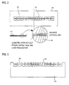
- Fig. 1 is a sectional view showing an X-ray measurement apparatus according to an embodiment of the invention. Elements the same as those in the related-art configuration described with reference to Fig. 6 are referred to by the same numerals respectively, and description thereof will be omitted.
- the embodiment is characterized by a configuration in which a flux shield 100 for partially passing or blocking a flux of a fan-shaped beam X-ray B2 shaped by a collimator 2 is inserted and disposed between an X-ray source 1 and a specimen 3 and behind the collimator 2.
- the flux shield 100 may be inserted near the rear of the collimator 2 or inserted just before the specimen 3 and at a distance from the collimator 2.
- the fundamental configuration of a measurement system is the same as the related-art configuration of Fig. 6 .
- Fig. 2 is a plan view showing a configuration example of the flux shield 100 used in the embodiment of the invention.
- the flux shield 100 has a plurality of fine slits 101 for passing or blocking the fan-shaped beam X-ray B2.
- the slit width increases in a direction from the central portion toward the peripheral portion so that the fan-shaped beam X-ray B2 blocking rate is high in the central portion while the fan-shaped beam X-ray B2 blocking rate decreases stepwise toward the peripheral portion.
- fine holes are formed by etching in a shield material (copper, stainless steel, iron, brass, tungsten, lead, or an alloy of those materials), which is comparatively thin in a range of from about several tens to several hundreds of micrometers.
- a shield material copper, stainless steel, iron, brass, tungsten, lead, or an alloy of those materials
- a shield material copper, stainless steel, iron, brass, tungsten, lead, or an alloy of those materials
- each slit 101 must be sufficiently small relative to the size of each radiation detection device of the X-ray detector 4. If the slits 101 are large in terms of size, uniform measurement cannot be performed among radiation detection devices, but ripples unique to each device occur due to the shield structure so that correct measurement cannot be achieved.
- Fig. 3 is a plan view showing another configuration example of a flux shield used in the embodiment of the invention.
- the configuration is characterized not by the slits formed by etching in Fig. 2 but by opening portions 102 (grooves) formed by grooving.
- the configuration has the same operation and effect as those in Fig. 2 but processing is easy.
- the sufficiently small slit can be explained as follows. That is, for 50% shield with slits about 0.03 mm wide, the slits about 0.03 mm wide may be provided continuously at a pitch of 0.06 mm.
- the slit width is expanded to change the area ratio between ribs and slits (opening portions) so that the transmitted dose can be controlled desirably.
- Fig. 4 is a plan view showing a further configuration example of the flux shield 100 used in the embodiment of the invention.
- the longitudinal direction of each slit 101 shown in Fig. 2 is perpendicular to the fan-shaped beam X-ray B2
- the longitudinal direction of each slit 103 in the configuration of Fig. 4 has an inclination ⁇ to the fan-shaped beam X-ray B2.
- the flux shield 100 can be used closely to the X-ray source I.
- the flux shield can be miniaturized and structurally integrated with the X-ray source easily.
- Fig. 5 is a perspective view showing a further configuration example of the flux shield used in the embodiment of the invention.
- This configuration example is characterized in that grooves are formed not by etching shown in Figs. 2 to 4 but by a processing method based on electric discharge machining (wire cut) using a wire cut processing machine.
- one single sheet of a comparatively thick plate material (about several millimeters) which has a shield effect by itself is grooved like comb teeth by a small-diameter wire to form grooves each having a width of several tens of micrometers.
- grooves are formed densely in a portion where the transmissivity should be lowered while grooves are formed sparsely in a portion where the transmissivity should be increased.
- the comb teeth are formed to be divergent like a fan shape in accordance with the angle of irradiation from the focus of the X-ray source 1.
- the single sheet of the comparatively thick plate material is used; however, a single sheet of a plate material whose material has a shield effect by itself may be used.
- the slits or grooves in Figs. 2 to 5 are explained one-dimensionally, the slits or grooves (opening portions) may be developed two-dimensionally and formed into spiral slits or grooves (opening portions). Further, ribbon-like foil may be vorticosely wound (through spacers etc.) densely in the central portion and sparsely in the periphery.
- the flux shield 100 used in the embodiment is combined with the function of the X-ray detector (line sensor) 4 in which gain and offset can be set for each radiation detection device, measurement can be performed with a higher accuracy.
- the flux shield 100 used in the embodiment can be also effectively used as a shield unit for making the irradiation dose to a ⁇ -ray detector uniform in a measurement apparatus using a ⁇ -ray as a radiation source.
Landscapes
- Physics & Mathematics (AREA)
- Spectroscopy & Molecular Physics (AREA)
- Engineering & Computer Science (AREA)
- General Engineering & Computer Science (AREA)
- High Energy & Nuclear Physics (AREA)
- Health & Medical Sciences (AREA)
- Toxicology (AREA)
- Life Sciences & Earth Sciences (AREA)
- Chemical & Material Sciences (AREA)
- Analytical Chemistry (AREA)
- Biochemistry (AREA)
- General Health & Medical Sciences (AREA)
- General Physics & Mathematics (AREA)
- Immunology (AREA)
- Pathology (AREA)
- Analysing Materials By The Use Of Radiation (AREA)
- Length-Measuring Devices Using Wave Or Particle Radiation (AREA)
Abstract
Description
- The present disclosure relates to an X-ray measurement apparatus which irradiates a specimen with an X-ray emitted from an X-ray source and detects a dose transmitted through the specimen by an X-ray detector. The present disclosure provides an X-ray measurement apparatus in which a shield for adjusting a spatial intensity distribution of a flux (radiant flux) from the X-ray source is improved to suppress the intensity of the flux in a central portion while reducing occurrence of beam hardening. The beam hardening is technically disclosed in
Patent Document 1. -
Fig. 6 is a perspective view showing a configuration example of an apparatus for measuring a basis weight of a specimen (such as paper, a film, a thin film sheet, etc:). A conical beam X-ray B1 from anX-ray source 1 is passed through acollimator 2 having aslit 21 so as to be shaped into a sliced fan-shaped beam X-ray B2. Aspecimen 3 running in the direction of an arrow F is irradiated with the fan-shaped beam X-ray B2. - The transmitted dose of the X-ray transmitted through the
specimen 3 is measured by a line sensor of anX-ray detector 4 which is disposed under the specimen so as to face theX-ray source 1. A specimen whose basis weight is known is measured in advance, and a standard curve L is drawn as shown inFig. 7 . A basis weight measurement of a specimen is performed based on the relationship between transmitted dose and basis weight. A coating amount measurement or a film thickness measurement of a specimen can be performed by the similar method. - As the
X-ray detector 4, a combination of a scintillator and a semiconductor photo acceptance device (CCD, C-MOS, etc.) may be used. The combination of the scintillator and the semiconductor photo acceptance device measures the radiation dose in such a manner that the scintillator is phosphorated when receiving an electron beam or photon energy (electromagnetic wave), and the phosphorescent intensity is converted into charges by the semiconductor photo acceptance device which is sensitive to visible light. Alternatively, a direct conversion type radiation detection device or the like may be used as theX-ray detector 4. In the direct conversion type radiation detection device, an electron beam or photon energy (electromagnetic wave) is received directly by a semiconductor photo acceptance device and converted into an amount of charges corresponding to the radiation intensity. - The output of the transmitted dose detected by the
X-ray detector 4 is typically of about 10 to 12 bits (1024 to 4096 gradations). The output varies depending on the distance between theX-ray source 1 and theX-ray detector 4 or the value of the X-ray source radiation angle (20 shown inFig. 6 ).Fig. 8 shows an example of characteristic of the output of theX-ray detector 4. - The central portion of the
X-ray detector 4 having a linear shape is near to theX-ray source 1. The sensitivity to the transmitted dose in the periphery of theX-ray detector 4 is lowered in accordance with a so-called cosine fourth law with respect to a radiation angle 0. Therefore, measurement conditions such as the output of theX-ray source 1 , the exposure time (integrated time), etc, are decided in order not to provide saturation for the maximum output in the central portion. - The measurement accuracy in the central portion which is high in dose differs from that in the periphery (outermost portion) which is low in dose. Decrease of about 1/2 is not a problem particularly. However, if the distance between the
X-ray source 1 and theX-ray detector 4 is short or if the intensity of the radiation angle of theX-ray source 1 has excessive directivity, only a fraction of the output in the central portion can be obtained in the periphery (outermost portion). Thus, desired measurement accuracy cannot be obtained in the periphery (outermost portion). - Therefore, as shown in
Fig. 9 , aflux shield 5 which is formed stepwise to be thicker in the central portion is inserted in any arbitrary position between theX-ray source 1 and thespecimen 3 so as to limit the transmitted dose only in the central portion which is high in flux. - The material of the
flux shield 5 is generally a metal foil sheet or a thin plate of aluminum, copper, iron, stainless steel or the like, a resin material such as a PET or acrylic plate, a composite material having a resin base material deposited with metal, or the like. - Although the
flux shield 5 shown inFig. 9 is shaped into three steps, it is not necessary to be always three steps. Theflux shield 5 may be shaped by processing such as molding or cutting so that the thickness thereof can vary continuously. Alternatively, theflux shield 5 does not have to have an integrated shape but may have a structure in which a larger number of thin sheets are laminated in the central portion. In such a manner, the shield effect can be adjusted easily while spatially continuous attenuation can be obtained. -
Fig. 10 shows the output characteristic of theX-ray detector 4 in the case where the dose in the central portion is limited in this manner. When the three-steppedflux shield 5 is inserted, four differences in step appear totally in the output characteristic, but decrease in the periphery can be suppressed as compared with that in the central portion. - When the number of steps of the
flux shield 5 is increased or when the steps of theflux shield 5 are made continuous to each other, each of the differences in step in the output characteristic can be made less. The dose is indeed decreased. However, as long as the dose in the central portion and the dose in the periphery can be uniform, satisfactory accuracy in the periphery can be secured when the exposure time is elongated or the output of the X-ray source I is increased. - In addition, the dose in the central portion may be limited more aggressively because slight reduction in the flux intensity in the central portion leads to a uniform dose after transmission.
- [Patent Document 1]
JP-T-2003-517577 -
Fig. 11 shows an X-ray intensity distribution immediately before an X-ray reaches thespecimen 3 when the dose in the central portion is limited by theflux shield 5 having the related-art configuration. Photon energy is radiated with a continuous spectrum corresponding to an X-ray tube voltage, However, the photon energy contributing to measurement has an energy distribution A in the outermost portion of the specimen due to absorption in a low energy band (area D inFig. 11 ) not higher than several keV by atmospheric absorption and a radiation window material (thin film of beryllium, mica, or the like). - Even when a flux radiated from the same X-ray source is limited only in the central portion by the flux shield, the attenuation of a short-wavelength and high-energy X-ray is low as shown by the reference sign B in
Fig. 11 . The energy distribution at the center of the specimen is shown by the reference sign C inFig. 11 . As illustrated, short-wavelength beam hardening occurs more intensively in the central portion than in the periphery (outermost portion). - Such a phenomenon occurs because the attenuation of the low-energy X-ray shown by the reference sign B is increased but the high-energy X-ray is not attenuated as the shield effect is stronger. As a result, there occurs a so-called beam hardening phenomenon in which peak energy is shifted to the high-energy side in the central portion of the specimen.
- When a thin-film specimen is measured with a high-energy X-ray, a satisfactory attenuation characteristic of the specimen cannot be obtained. Thus, a measurement result cannot be obtained with a high measurement accuracy. In addition, the photon energy flux which measures the transmission characteristic differs between the central portion and the periphery. Accordingly, the measurement result does not coincide with the standard curve (relationship between attenuation characteristic and basis weight) obtained in advance as shown in
Fig. 7 . That is, when a specimen with the same thickness (basis weight) as a specimen measured in advance is measured, the reduced output in the periphery leads to wrong measurement as if the specimen were thick. - Exemplary embodiments of the present invention provide an X-ray measurement apparatus in which a spatial intensity distribution of a flux is improved while suppressing occurrence of beam hardening, and the energy distribution and the dose of the flux are uniform between a central portion and a periphery so that an error in measurement caused by a measurement position can be reduced.
- An X-ray measurement apparatus, according to an exemplary embodiment, comprises:
- an X-ray source configured to emit an X-ray to irradiate a specimen with the X-ray;
- a collimator configured to shape a beam of the X-ray emitted from the X-ray source into a sliced fan-shaped beam x-ray;
- a flux shield configured to block a part of a flux of the fan-shaped beam X-ray so as to suppress beam hardening while adjusting an energy intensity distribution of the flux, the flux shield being placed between the collimator and the specimen; and
- an X-ray detector configured to detect a dose transmitted through the specimen.
- Other features and advantages may be apparent from the following detailed description, the accompanying drawings and the claims.
-
-
Fig. 1 is a sectional view showing an X-ray measurement apparatus according to an embodiment of the invention; -
Fig. 2 is a plan view showing a configuration example of a flux shield used in the embodiment of the invention; -
Fig. 3 is a plan view showing another configuration example of the flux shield used in the embodiment of the invention; -
Fig. 4 is a plan view showing a further configuration example of the flux shield used in the embodiment af the invention; -
Fig. 5 is a perspective view showing a further configuration example of the flux shield used in the embodiment of the invention; -
Fig. 6 is a perspective view showing a configuration example of an apparatus for measuring a basis weight of a specimen; -
Fig. 7 is a view showing a relationship between a basis weight and a transmitted dose; -
Fig. 8 is a view showing a relationship between specimen width direction and a transmitted dose; -
Fig. 9 is a perspective view showing a configuration example of a basis weight measuring apparatus of a specimen having a flux shield; and -
Fig. 10 is a view showing a relationship between specimen width direction and a transmitted dose when the flux shield is used; and -
Fig. 11 is a view showing a relationship between photon energy and X-ray intensity for explaining beam hardening by the flux shield. - Exemplary embodiments will be described below in detail with reference to the drawings.
Fig. 1 is a sectional view showing an X-ray measurement apparatus according to an embodiment of the invention. Elements the same as those in the related-art configuration described with reference toFig. 6 are referred to by the same numerals respectively, and description thereof will be omitted. - The embodiment is characterized by a configuration in which a
flux shield 100 for partially passing or blocking a flux of a fan-shaped beam X-ray B2 shaped by acollimator 2 is inserted and disposed between anX-ray source 1 and aspecimen 3 and behind thecollimator 2. - The
flux shield 100 may be inserted near the rear of thecollimator 2 or inserted just before thespecimen 3 and at a distance from thecollimator 2. The fundamental configuration of a measurement system is the same as the related-art configuration ofFig. 6 . -
Fig. 2 is a plan view showing a configuration example of theflux shield 100 used in the embodiment of the invention. Theflux shield 100 has a plurality offine slits 101 for passing or blocking the fan-shaped beam X-ray B2. The slit width increases in a direction from the central portion toward the peripheral portion so that the fan-shaped beam X-ray B2 blocking rate is high in the central portion while the fan-shaped beam X-ray B2 blocking rate decreases stepwise toward the peripheral portion. - In the illustrated structure, fine holes (slits) are formed by etching in a shield material (copper, stainless steel, iron, brass, tungsten, lead, or an alloy of those materials), which is comparatively thin in a range of from about several tens to several hundreds of micrometers. When radiation rays cannot be absorbed satisfactorily by a single shield sheet, a plurality of shield sheets are laminated in tight contact with each other. As illustrated in the expanded view of
Fig. 2 , it is preferable to change the pitch of slits from one sheet to another in accordance with the inclination of the flux. - The size of each slit 101 must be sufficiently small relative to the size of each radiation detection device of the
X-ray detector 4. If theslits 101 are large in terms of size, uniform measurement cannot be performed among radiation detection devices, but ripples unique to each device occur due to the shield structure so that correct measurement cannot be achieved. -
Fig. 3 is a plan view showing another configuration example of a flux shield used in the embodiment of the invention. The configuration is characterized not by the slits formed by etching inFig. 2 but by opening portions 102 (grooves) formed by grooving. The configuration has the same operation and effect as those inFig. 2 but processing is easy. - The size of the
slits 101 will be considered in the configuration shown inFig. 1 . Assume that a size of each detection device is 0.8 mm by 0.8 mm. When the distance between the focus position of theX-ray source 1 and theX-ray detector 4 is 500 mm and the distance between the focus position of theX-ray source 1 and the fine slittype flux shield 100 is 200 mm, the size equivalent to one device is expressed as 0.8×(200/500)=0.32 mm when the X-ray passes through theflux shield 100. - When each slit is sufficiently small relative to the size equivalent to one device, it is possible to prevent ripples due to the fine slit
type flux shield 100 from occurring. For example, the sufficiently small slit can be explained as follows. That is, for 50% shield with slits about 0.03 mm wide, the slits about 0.03 mm wide may be provided continuously at a pitch of 0.06 mm. - With such a design, a flux transmitted through five slits reaches one device. To lower the transmissivity in the central portion to 50% and permit transmissivity of 100% in the periphery which is the lowest in dose, the slit width is expanded to change the area ratio between ribs and slits (opening portions) so that the transmitted dose can be controlled desirably.
-
Fig. 4 is a plan view showing a further configuration example of theflux shield 100 used in the embodiment of the invention. Although the longitudinal direction of each slit 101 shown inFig. 2 is perpendicular to the fan-shaped beam X-ray B2, the longitudinal direction of each slit 103 in the configuration ofFig. 4 has an inclination β to the fan-shaped beam X-ray B2. - When the fine opening portions are inclined at a predetermined angle in this manner, there is an effect that fluctuation in each detection device can hardly occur in comparison with the case where the opening portions are provided to be perpendicular. It is therefore possible to roughen the degree of fine processing to some extent. Further, the
flux shield 100 can be used closely to the X-ray source I. Thus, the flux shield can be miniaturized and structurally integrated with the X-ray source easily. -
Fig. 5 is a perspective view showing a further configuration example of the flux shield used in the embodiment of the invention. This configuration example is characterized in that grooves are formed not by etching shown inFigs. 2 to 4 but by a processing method based on electric discharge machining (wire cut) using a wire cut processing machine. - According to this processing method, one single sheet of a comparatively thick plate material (about several millimeters) which has a shield effect by itself is grooved like comb teeth by a small-diameter wire to form grooves each having a width of several tens of micrometers. In the same manner as in
Figs. 2 to 4 , grooves are formed densely in a portion where the transmissivity should be lowered while grooves are formed sparsely in a portion where the transmissivity should be increased. Further, the comb teeth are formed to be divergent like a fan shape in accordance with the angle of irradiation from the focus of theX-ray source 1. In this embodiment, the single sheet of the comparatively thick plate material is used; however, a single sheet of a plate material whose material has a shield effect by itself may be used. - Although the slits or grooves in
Figs. 2 to 5 are explained one-dimensionally, the slits or grooves (opening portions) may be developed two-dimensionally and formed into spiral slits or grooves (opening portions). Further, ribbon-like foil may be vorticosely wound (through spacers etc.) densely in the central portion and sparsely in the periphery. - When the
flux shield 100 used in the embodiment is combined with the function of the X-ray detector (line sensor) 4 in which gain and offset can be set for each radiation detection device, measurement can be performed with a higher accuracy. - The
flux shield 100 used in the embodiment can be also effectively used as a shield unit for making the irradiation dose to a β-ray detector uniform in a measurement apparatus using a β-ray as a radiation source. - According to the embodiment of the invention, the following effects can be expected.
- (1) A dose in a central portion which is high in dose is limited so that the dose can be uniform between the periphery and the central portion. Thus, the output of the X-ray detector can be uniform to solve a problem that a satisfactory dynamic range cannot be secured in some measurement site.
- (2) Beam hardening can be suppressed while the dose in the central portion which is high in dose is limited. Thus, a standard curve obtained in a representative portion such as the central portion coincides with any portion of the measurement range with a high accuracy.
- (3) Since a uniform dose can be applied, a good sensitive dose can be selected for a specimen even if the specimen is very thin. Accordingly, the effect of improvement is great particularly under the conditions of irradiation from a short distance at which the dose distribution becomes intensive.
- While the invention has been described with respect to a limited number of embodiments, those skilled in the art, having benefit of this disclosure, will appreciate that other embodiments can be devised which do not depart from the scope of the invention as disclosed herein. Accordingly, the scope of the invention should be limited only by the attached claims.
Claims (11)
- An X-ray measurement apparatus comprising:an X-ray source configured to emit an X-ray to irradiate a specimen with the X-ray;a collimator configured to shape a beam of the X-ray emitted from the X-ray source into a sliced fan-shaped beam x-ray;a flux shield configured to block a part of a flux of the fan-shaped beam X-ray so as to suppress beam hardening while adjusting an energy intensity distribution of the flux, the flux shield being placed between the collimator and the specimen; andan X-ray detector configured to detect a dose transmitted through the specimen.
- The X-ray measurement apparatus according to Claim 1,
wherein the flux shield has a plurality of slits or grooves which are formed by fine processing, and
wherein a width of each of the slits or grooves is sufficiently small relative to a size of a detection device of the X-ray detector. - The X-ray measurement apparatus according to Claim 1 or 2,
wherein the flux shield is formed to increase a shield rate of the flux in a central portion of the flux shield based on a dose distribution or an energy intensity distribution of the flux. - The X-ray measurement apparatus according to any one of Claims 1 through 3, wherein the flux shield is formed to have a dose distribution or an energy intensity distribution of the flux uniform between a central portion and a peripheral portion of the distribution.
- The X-ray measurement apparatus according to any one of Claims 1 through 4,
wherein the slits or grooves of the flux shield are arranged in irregular intervals, and
wherein a dose distribution and an energy intensity distribution of the flux are controlled by an area ratio between the slits or grooves and ribs. - The X-ray measurement apparatus according to any one of Claims 1 through 5, wherein the flux shield includes a plurality of laminated metal foil sheets or metal thin plates, and each of the metal foil sheets or metal thin plates has a plurality of slits or grooves formed by fine processing.
- The X-ray measurement apparatus according to Claim 6, wherein pitches of the slits or grooves of the respective metal foil sheets or metal thin plates are different from each other based on a divergence from a focus point of the X-ray source.
- The X-ray measurement apparatus according to any one of Claims 1 through 5, wherein the flux shield is composed of a single sheet of a plate material whose material or thickness has a flux shield effect, and the flux shield is shaped like comb teeth having a plurality of grooves which is formed by fine processing.
- The X-ray measurement apparatus according to Claim 8, wherein the flux shield shaped like comb teeth are formed to be divergent like a fan shape based on a divergence from a focus point of the X-ray source.
- The X-ray measurement apparatus according to Claim 2 or 3,
wherein widths of the slits or grooves increase in a direction from the central portion toward a peripheral portion of the flux shield. - The X-ray measurement apparatus according to Claim 2 or 3,
wherein
a longitudinal direction of each of the slits or grooves has an inclination to the fan-shaped beam X-ray.
Applications Claiming Priority (1)
| Application Number | Priority Date | Filing Date | Title |
|---|---|---|---|
| JP2009268585A JP4911373B2 (en) | 2009-11-26 | 2009-11-26 | X-ray measuring device |
Publications (3)
| Publication Number | Publication Date |
|---|---|
| EP2333528A2 true EP2333528A2 (en) | 2011-06-15 |
| EP2333528A3 EP2333528A3 (en) | 2011-12-21 |
| EP2333528B1 EP2333528B1 (en) | 2015-08-05 |
Family
ID=43769198
Family Applications (1)
| Application Number | Title | Priority Date | Filing Date |
|---|---|---|---|
| EP10192649.1A Not-in-force EP2333528B1 (en) | 2009-11-26 | 2010-11-26 | X-Ray measurement apparatus |
Country Status (4)
| Country | Link |
|---|---|
| US (1) | US8488744B2 (en) |
| EP (1) | EP2333528B1 (en) |
| JP (1) | JP4911373B2 (en) |
| CN (1) | CN102081164B (en) |
Cited By (1)
| Publication number | Priority date | Publication date | Assignee | Title |
|---|---|---|---|---|
| CN113238298A (en) * | 2021-07-09 | 2021-08-10 | 同方威视技术股份有限公司 | Inspection system and method |
Families Citing this family (20)
| Publication number | Priority date | Publication date | Assignee | Title |
|---|---|---|---|---|
| US8294094B1 (en) * | 2011-08-16 | 2012-10-23 | Hermes Microvision Inc. | Method and apparatus for reducing substrate edge effect during inspection |
| CN102607476B (en) * | 2012-01-05 | 2016-07-13 | 黑龙江省科学院技术物理研究所 | Adjustable high-precision X-ray thickness gauge and method of testing |
| JP5648965B2 (en) * | 2012-03-23 | 2015-01-07 | 克広 土橋 | Apparatus for adjusting spatial intensity distribution of radiation and spatial distribution of energy, and X-ray generator and radiation detector using the adjusting apparatus |
| JP6096419B2 (en) * | 2012-04-12 | 2017-03-15 | 株式会社堀場製作所 | X-ray detector |
| US20130322602A1 (en) * | 2012-05-31 | 2013-12-05 | General Electric Company | Internal shielding x-ray tube |
| TWI488612B (en) * | 2012-11-20 | 2015-06-21 | Iner Aec Executive Yuan | Apparatus for x-ray photography |
| CN103861541B (en) * | 2012-12-07 | 2015-07-08 | 汇佳生物仪器(上海)有限公司 | Method and equipment for increasing irradiation dose homogeneity of ray processing device |
| WO2015106983A1 (en) * | 2014-01-14 | 2015-07-23 | Koninklijke Philips N.V. | X-ray emitting device with an attenuating element for an x-ray imaging apparatus |
| WO2017009363A1 (en) * | 2015-07-14 | 2017-01-19 | Koninklijke Philips N.V. | Imaging with modulated x-ray radiation |
| JP6533006B2 (en) * | 2015-07-14 | 2019-06-19 | コーニンクレッカ フィリップス エヌ ヴェKoninklijke Philips N.V. | Imaging with enhanced x-ray radiation |
| CN109688930A (en) * | 2016-09-08 | 2019-04-26 | 皇家飞利浦有限公司 | Source grating for x-ray imaging |
| JP6717784B2 (en) * | 2017-06-30 | 2020-07-08 | アンリツインフィビス株式会社 | Article inspection apparatus and calibration method thereof |
| KR102070698B1 (en) * | 2017-11-28 | 2020-01-29 | (주)자비스 | An X-Ray Tube Apparatus with a Structure of Focusing on a Target for Protecting an Object |
| DE102017221924B3 (en) * | 2017-12-05 | 2019-05-02 | Siemens Healthcare Gmbh | Method for merging an analysis data set with an image data record, positioning device and computer program |
| CN109273131B (en) * | 2018-10-31 | 2024-07-02 | 同方威视技术股份有限公司 | Collimator assembly and radiation detection device |
| KR20200052521A (en) * | 2018-11-07 | 2020-05-15 | (주)자비스 | A Method for Selecting a Investigating Part in a High Density Object and an Apparatus for the Same |
| CN110793474A (en) * | 2019-12-05 | 2020-02-14 | 河南省计量科学研究院 | An X-ray focus measurement device |
| CN113064196B (en) * | 2021-03-18 | 2023-06-27 | 西北核技术研究所 | Method and system for rapidly discriminating radiation sensitive position of electronic system based on X-rays |
| US20250237500A1 (en) * | 2024-01-19 | 2025-07-24 | Thermo EGS Gauging LLC | X-ray apodization filter |
| CN119618117B (en) * | 2024-12-11 | 2025-09-26 | 合肥工业大学 | X-ray measurement facula collimation system |
Family Cites Families (16)
| Publication number | Priority date | Publication date | Assignee | Title |
|---|---|---|---|---|
| US3944833A (en) * | 1968-08-23 | 1976-03-16 | E M I Limited | Apparatus for examining a body by radiation such as X or gamma radiation |
| US4286167A (en) * | 1979-05-14 | 1981-08-25 | Varian Associates, Inc. | Multi-element X-ray equalizing filter |
| JPS58209273A (en) * | 1982-05-31 | 1983-12-06 | Eiichi Takenaka | X-ray television image pickup device |
| GB8317880D0 (en) * | 1983-07-01 | 1983-08-03 | Searle & Co | Structure and synthesis of interferons |
| DE3425295C2 (en) * | 1984-07-10 | 1986-07-24 | Hoesch Ag, 4600 Dortmund | Device for measuring the thickness profile of rolled sheet metal strips |
| US5231655A (en) * | 1991-12-06 | 1993-07-27 | General Electric Company | X-ray collimator |
| US5317616A (en) * | 1992-03-19 | 1994-05-31 | Wisconsin Alumni Research Foundation | Method and apparatus for radiation therapy |
| AU6504699A (en) * | 1998-10-06 | 2000-04-26 | Cardiac Mariners, Inc. | Beam hardening filter for x-ray source |
| JP2000245731A (en) * | 1999-03-04 | 2000-09-12 | Toshiba Corp | X-ray equipment |
| JP3644306B2 (en) * | 1999-05-10 | 2005-04-27 | 三菱電機株式会社 | Radiation detector |
| JP2003057397A (en) * | 2001-08-17 | 2003-02-26 | Mitsubishi Electric Corp | Beam current attenuator |
| JP4041025B2 (en) * | 2003-07-15 | 2008-01-30 | ジーイー・メディカル・システムズ・グローバル・テクノロジー・カンパニー・エルエルシー | X-ray distribution adjustment filter device and X-ray CT device using the same |
| DE602005004653T2 (en) | 2004-03-17 | 2009-01-29 | Philips Intellectual Property & Standards Gmbh | Correction of radiation hardening and attenuation in coherent scatter computed tomography (CSCT) |
| JP2006288554A (en) * | 2005-04-07 | 2006-10-26 | Toshiba Corp | X-ray diagnostic apparatus and image data generation method |
| US7330535B2 (en) * | 2005-11-10 | 2008-02-12 | General Electric Company | X-ray flux management device |
| US8031840B2 (en) | 2006-12-04 | 2011-10-04 | Koninklijke Philips Electronics N.V. | Beam filter, particularly for x-rays |
-
2009
- 2009-11-26 JP JP2009268585A patent/JP4911373B2/en not_active Expired - Fee Related
-
2010
- 2010-11-25 CN CN201010566141.1A patent/CN102081164B/en not_active Expired - Fee Related
- 2010-11-26 US US12/954,710 patent/US8488744B2/en not_active Expired - Fee Related
- 2010-11-26 EP EP10192649.1A patent/EP2333528B1/en not_active Not-in-force
Non-Patent Citations (1)
| Title |
|---|
| None |
Cited By (1)
| Publication number | Priority date | Publication date | Assignee | Title |
|---|---|---|---|---|
| CN113238298A (en) * | 2021-07-09 | 2021-08-10 | 同方威视技术股份有限公司 | Inspection system and method |
Also Published As
| Publication number | Publication date |
|---|---|
| CN102081164A (en) | 2011-06-01 |
| JP4911373B2 (en) | 2012-04-04 |
| EP2333528B1 (en) | 2015-08-05 |
| JP2011112482A (en) | 2011-06-09 |
| US20110122993A1 (en) | 2011-05-26 |
| CN102081164B (en) | 2013-09-18 |
| EP2333528A3 (en) | 2011-12-21 |
| US8488744B2 (en) | 2013-07-16 |
Similar Documents
| Publication | Publication Date | Title |
|---|---|---|
| EP2333528B1 (en) | X-Ray measurement apparatus | |
| DE69200634T2 (en) | X-ray machine with a K-edge filter. | |
| EP1029427B1 (en) | A method and a device for planar beam radiography and a radiation detector | |
| JP5648965B2 (en) | Apparatus for adjusting spatial intensity distribution of radiation and spatial distribution of energy, and X-ray generator and radiation detector using the adjusting apparatus | |
| AU766413B2 (en) | Radiation detector, an apparatus for use in planar beam radiography and a method for detecting ionizing radiation | |
| CA2893877A1 (en) | A wavelength dispersive crystal spectrometer, a x-ray fluorescence device and method therein | |
| CN101002109B (en) | Anti-scatter-grid for a radiation detector | |
| JP4510823B2 (en) | Device for collimating electromagnetic radiation | |
| JP2015520362A (en) | Apparatus and method for hadron beam verification | |
| KR20210142605A (en) | Radiation-based thickness gauge | |
| US9036789B2 (en) | X-ray apparatus and its adjusting method | |
| JP2008510131A (en) | Arrangement of scintillator and anti-scatter grid | |
| JPH05256950A (en) | Solid detector for x-ray computer tomography | |
| US9093187B1 (en) | Fixed gantry CT system having a non-uniform slit | |
| JP2011112561A (en) | X-ray measurement system | |
| CA1118538A (en) | Device for examining a body by means of penetrating radiation | |
| US20020003859A1 (en) | X-ray analysis apparatus provided with a multilayer mirror and an exit collimator | |
| JPH08243098A (en) | X-ray ct equipment | |
| RU182076U1 (en) | X-ray fluorescence wire scanner of profiles of beams of ionizing radiation | |
| JPH0698883A (en) | X-ray ct apparatus | |
| US12287440B2 (en) | Method for manufacturing a flux detector of a first and a second ionizing radiation | |
| KR20190126621A (en) | The device for measurement of transmittance by thickness for calculating the radiation attenuation coefficient in one direction | |
| CN107847200B (en) | Imaging devices and systems utilizing enhanced X-ray radiation | |
| Shikhaliev | Hard x‐ray detector based on microchannel plates | |
| KR101799655B1 (en) | Apparatus and method for detecting gamma-ray |
Legal Events
| Date | Code | Title | Description |
|---|---|---|---|
| PUAI | Public reference made under article 153(3) epc to a published international application that has entered the european phase |
Free format text: ORIGINAL CODE: 0009012 |
|
| AK | Designated contracting states |
Kind code of ref document: A2 Designated state(s): AL AT BE BG CH CY CZ DE DK EE ES FI FR GB GR HR HU IE IS IT LI LT LU LV MC MK MT NL NO PL PT RO RS SE SI SK SM TR |
|
| AX | Request for extension of the european patent |
Extension state: BA ME |
|
| PUAL | Search report despatched |
Free format text: ORIGINAL CODE: 0009013 |
|
| AK | Designated contracting states |
Kind code of ref document: A3 Designated state(s): AL AT BE BG CH CY CZ DE DK EE ES FI FR GB GR HR HU IE IS IT LI LT LU LV MC MK MT NL NO PL PT RO RS SE SI SK SM TR |
|
| AX | Request for extension of the european patent |
Extension state: BA ME |
|
| RIC1 | Information provided on ipc code assigned before grant |
Ipc: G21K 1/02 20060101ALI20111116BHEP Ipc: G01N 23/00 20060101AFI20111116BHEP |
|
| 17P | Request for examination filed |
Effective date: 20120615 |
|
| REG | Reference to a national code |
Ref country code: DE Ref legal event code: R079 Ref document number: 602010026394 Country of ref document: DE Free format text: PREVIOUS MAIN CLASS: G01N0023000000 Ipc: G01N0023083000 |
|
| GRAP | Despatch of communication of intention to grant a patent |
Free format text: ORIGINAL CODE: EPIDOSNIGR1 |
|
| RIC1 | Information provided on ipc code assigned before grant |
Ipc: G21K 1/10 20060101ALI20150210BHEP Ipc: G21K 1/02 20060101ALI20150210BHEP Ipc: G01N 23/083 20060101AFI20150210BHEP |
|
| INTG | Intention to grant announced |
Effective date: 20150313 |
|
| GRAS | Grant fee paid |
Free format text: ORIGINAL CODE: EPIDOSNIGR3 |
|
| GRAA | (expected) grant |
Free format text: ORIGINAL CODE: 0009210 |
|
| AK | Designated contracting states |
Kind code of ref document: B1 Designated state(s): AL AT BE BG CH CY CZ DE DK EE ES FI FR GB GR HR HU IE IS IT LI LT LU LV MC MK MT NL NO PL PT RO RS SE SI SK SM TR |
|
| REG | Reference to a national code |
Ref country code: GB Ref legal event code: FG4D |
|
| REG | Reference to a national code |
Ref country code: CH Ref legal event code: EP |
|
| REG | Reference to a national code |
Ref country code: AT Ref legal event code: REF Ref document number: 740998 Country of ref document: AT Kind code of ref document: T Effective date: 20150815 |
|
| REG | Reference to a national code |
Ref country code: IE Ref legal event code: FG4D |
|
| REG | Reference to a national code |
Ref country code: DE Ref legal event code: R096 Ref document number: 602010026394 Country of ref document: DE |
|
| REG | Reference to a national code |
Ref country code: AT Ref legal event code: MK05 Ref document number: 740998 Country of ref document: AT Kind code of ref document: T Effective date: 20150805 |
|
| REG | Reference to a national code |
Ref country code: LT Ref legal event code: MG4D |
|
| REG | Reference to a national code |
Ref country code: NL Ref legal event code: MP Effective date: 20150805 |
|
| PG25 | Lapsed in a contracting state [announced via postgrant information from national office to epo] |
Ref country code: GR Free format text: LAPSE BECAUSE OF FAILURE TO SUBMIT A TRANSLATION OF THE DESCRIPTION OR TO PAY THE FEE WITHIN THE PRESCRIBED TIME-LIMIT Effective date: 20151106 Ref country code: LV Free format text: LAPSE BECAUSE OF FAILURE TO SUBMIT A TRANSLATION OF THE DESCRIPTION OR TO PAY THE FEE WITHIN THE PRESCRIBED TIME-LIMIT Effective date: 20150805 Ref country code: NO Free format text: LAPSE BECAUSE OF FAILURE TO SUBMIT A TRANSLATION OF THE DESCRIPTION OR TO PAY THE FEE WITHIN THE PRESCRIBED TIME-LIMIT Effective date: 20151105 Ref country code: FI Free format text: LAPSE BECAUSE OF FAILURE TO SUBMIT A TRANSLATION OF THE DESCRIPTION OR TO PAY THE FEE WITHIN THE PRESCRIBED TIME-LIMIT Effective date: 20150805 Ref country code: LT Free format text: LAPSE BECAUSE OF FAILURE TO SUBMIT A TRANSLATION OF THE DESCRIPTION OR TO PAY THE FEE WITHIN THE PRESCRIBED TIME-LIMIT Effective date: 20150805 |
|
| PG25 | Lapsed in a contracting state [announced via postgrant information from national office to epo] |
Ref country code: ES Free format text: LAPSE BECAUSE OF FAILURE TO SUBMIT A TRANSLATION OF THE DESCRIPTION OR TO PAY THE FEE WITHIN THE PRESCRIBED TIME-LIMIT Effective date: 20150805 Ref country code: RS Free format text: LAPSE BECAUSE OF FAILURE TO SUBMIT A TRANSLATION OF THE DESCRIPTION OR TO PAY THE FEE WITHIN THE PRESCRIBED TIME-LIMIT Effective date: 20150805 Ref country code: PT Free format text: LAPSE BECAUSE OF FAILURE TO SUBMIT A TRANSLATION OF THE DESCRIPTION OR TO PAY THE FEE WITHIN THE PRESCRIBED TIME-LIMIT Effective date: 20151207 Ref country code: PL Free format text: LAPSE BECAUSE OF FAILURE TO SUBMIT A TRANSLATION OF THE DESCRIPTION OR TO PAY THE FEE WITHIN THE PRESCRIBED TIME-LIMIT Effective date: 20150805 Ref country code: HR Free format text: LAPSE BECAUSE OF FAILURE TO SUBMIT A TRANSLATION OF THE DESCRIPTION OR TO PAY THE FEE WITHIN THE PRESCRIBED TIME-LIMIT Effective date: 20150805 Ref country code: AT Free format text: LAPSE BECAUSE OF FAILURE TO SUBMIT A TRANSLATION OF THE DESCRIPTION OR TO PAY THE FEE WITHIN THE PRESCRIBED TIME-LIMIT Effective date: 20150805 Ref country code: SE Free format text: LAPSE BECAUSE OF FAILURE TO SUBMIT A TRANSLATION OF THE DESCRIPTION OR TO PAY THE FEE WITHIN THE PRESCRIBED TIME-LIMIT Effective date: 20150805 Ref country code: IS Free format text: LAPSE BECAUSE OF FAILURE TO SUBMIT A TRANSLATION OF THE DESCRIPTION OR TO PAY THE FEE WITHIN THE PRESCRIBED TIME-LIMIT Effective date: 20151205 |
|
| PG25 | Lapsed in a contracting state [announced via postgrant information from national office to epo] |
Ref country code: NL Free format text: LAPSE BECAUSE OF FAILURE TO SUBMIT A TRANSLATION OF THE DESCRIPTION OR TO PAY THE FEE WITHIN THE PRESCRIBED TIME-LIMIT Effective date: 20150805 |
|
| PG25 | Lapsed in a contracting state [announced via postgrant information from national office to epo] |
Ref country code: DK Free format text: LAPSE BECAUSE OF FAILURE TO SUBMIT A TRANSLATION OF THE DESCRIPTION OR TO PAY THE FEE WITHIN THE PRESCRIBED TIME-LIMIT Effective date: 20150805 Ref country code: SK Free format text: LAPSE BECAUSE OF FAILURE TO SUBMIT A TRANSLATION OF THE DESCRIPTION OR TO PAY THE FEE WITHIN THE PRESCRIBED TIME-LIMIT Effective date: 20150805 Ref country code: EE Free format text: LAPSE BECAUSE OF FAILURE TO SUBMIT A TRANSLATION OF THE DESCRIPTION OR TO PAY THE FEE WITHIN THE PRESCRIBED TIME-LIMIT Effective date: 20150805 Ref country code: IT Free format text: LAPSE BECAUSE OF FAILURE TO SUBMIT A TRANSLATION OF THE DESCRIPTION OR TO PAY THE FEE WITHIN THE PRESCRIBED TIME-LIMIT Effective date: 20150805 Ref country code: CZ Free format text: LAPSE BECAUSE OF FAILURE TO SUBMIT A TRANSLATION OF THE DESCRIPTION OR TO PAY THE FEE WITHIN THE PRESCRIBED TIME-LIMIT Effective date: 20150805 |
|
| REG | Reference to a national code |
Ref country code: DE Ref legal event code: R097 Ref document number: 602010026394 Country of ref document: DE |
|
| PG25 | Lapsed in a contracting state [announced via postgrant information from national office to epo] |
Ref country code: RO Free format text: LAPSE BECAUSE OF FAILURE TO SUBMIT A TRANSLATION OF THE DESCRIPTION OR TO PAY THE FEE WITHIN THE PRESCRIBED TIME-LIMIT Effective date: 20150805 |
|
| PLBE | No opposition filed within time limit |
Free format text: ORIGINAL CODE: 0009261 |
|
| STAA | Information on the status of an ep patent application or granted ep patent |
Free format text: STATUS: NO OPPOSITION FILED WITHIN TIME LIMIT |
|
| PG25 | Lapsed in a contracting state [announced via postgrant information from national office to epo] |
Ref country code: MC Free format text: LAPSE BECAUSE OF FAILURE TO SUBMIT A TRANSLATION OF THE DESCRIPTION OR TO PAY THE FEE WITHIN THE PRESCRIBED TIME-LIMIT Effective date: 20150805 Ref country code: LU Free format text: LAPSE BECAUSE OF FAILURE TO SUBMIT A TRANSLATION OF THE DESCRIPTION OR TO PAY THE FEE WITHIN THE PRESCRIBED TIME-LIMIT Effective date: 20151126 |
|
| REG | Reference to a national code |
Ref country code: CH Ref legal event code: PL |
|
| 26N | No opposition filed |
Effective date: 20160509 |
|
| GBPC | Gb: european patent ceased through non-payment of renewal fee |
Effective date: 20151126 |
|
| PG25 | Lapsed in a contracting state [announced via postgrant information from national office to epo] |
Ref country code: LI Free format text: LAPSE BECAUSE OF NON-PAYMENT OF DUE FEES Effective date: 20151130 Ref country code: CH Free format text: LAPSE BECAUSE OF NON-PAYMENT OF DUE FEES Effective date: 20151130 |
|
| REG | Reference to a national code |
Ref country code: IE Ref legal event code: MM4A |
|
| REG | Reference to a national code |
Ref country code: FR Ref legal event code: ST Effective date: 20160729 |
|
| PG25 | Lapsed in a contracting state [announced via postgrant information from national office to epo] |
Ref country code: SI Free format text: LAPSE BECAUSE OF FAILURE TO SUBMIT A TRANSLATION OF THE DESCRIPTION OR TO PAY THE FEE WITHIN THE PRESCRIBED TIME-LIMIT Effective date: 20150805 |
|
| PG25 | Lapsed in a contracting state [announced via postgrant information from national office to epo] |
Ref country code: IE Free format text: LAPSE BECAUSE OF NON-PAYMENT OF DUE FEES Effective date: 20151126 Ref country code: GB Free format text: LAPSE BECAUSE OF NON-PAYMENT OF DUE FEES Effective date: 20151126 |
|
| PG25 | Lapsed in a contracting state [announced via postgrant information from national office to epo] |
Ref country code: FR Free format text: LAPSE BECAUSE OF NON-PAYMENT OF DUE FEES Effective date: 20151130 |
|
| PG25 | Lapsed in a contracting state [announced via postgrant information from national office to epo] |
Ref country code: BE Free format text: LAPSE BECAUSE OF FAILURE TO SUBMIT A TRANSLATION OF THE DESCRIPTION OR TO PAY THE FEE WITHIN THE PRESCRIBED TIME-LIMIT Effective date: 20150805 |
|
| PGFP | Annual fee paid to national office [announced via postgrant information from national office to epo] |
Ref country code: DE Payment date: 20161123 Year of fee payment: 7 |
|
| PG25 | Lapsed in a contracting state [announced via postgrant information from national office to epo] |
Ref country code: HU Free format text: LAPSE BECAUSE OF FAILURE TO SUBMIT A TRANSLATION OF THE DESCRIPTION OR TO PAY THE FEE WITHIN THE PRESCRIBED TIME-LIMIT; INVALID AB INITIO Effective date: 20101126 Ref country code: SM Free format text: LAPSE BECAUSE OF FAILURE TO SUBMIT A TRANSLATION OF THE DESCRIPTION OR TO PAY THE FEE WITHIN THE PRESCRIBED TIME-LIMIT Effective date: 20150805 Ref country code: BG Free format text: LAPSE BECAUSE OF FAILURE TO SUBMIT A TRANSLATION OF THE DESCRIPTION OR TO PAY THE FEE WITHIN THE PRESCRIBED TIME-LIMIT Effective date: 20150805 |
|
| PG25 | Lapsed in a contracting state [announced via postgrant information from national office to epo] |
Ref country code: CY Free format text: LAPSE BECAUSE OF FAILURE TO SUBMIT A TRANSLATION OF THE DESCRIPTION OR TO PAY THE FEE WITHIN THE PRESCRIBED TIME-LIMIT Effective date: 20150805 |
|
| PG25 | Lapsed in a contracting state [announced via postgrant information from national office to epo] |
Ref country code: MT Free format text: LAPSE BECAUSE OF FAILURE TO SUBMIT A TRANSLATION OF THE DESCRIPTION OR TO PAY THE FEE WITHIN THE PRESCRIBED TIME-LIMIT Effective date: 20150805 Ref country code: TR Free format text: LAPSE BECAUSE OF FAILURE TO SUBMIT A TRANSLATION OF THE DESCRIPTION OR TO PAY THE FEE WITHIN THE PRESCRIBED TIME-LIMIT Effective date: 20150805 |
|
| REG | Reference to a national code |
Ref country code: DE Ref legal event code: R119 Ref document number: 602010026394 Country of ref document: DE |
|
| PG25 | Lapsed in a contracting state [announced via postgrant information from national office to epo] |
Ref country code: MK Free format text: LAPSE BECAUSE OF FAILURE TO SUBMIT A TRANSLATION OF THE DESCRIPTION OR TO PAY THE FEE WITHIN THE PRESCRIBED TIME-LIMIT Effective date: 20150805 |
|
| PG25 | Lapsed in a contracting state [announced via postgrant information from national office to epo] |
Ref country code: AL Free format text: LAPSE BECAUSE OF FAILURE TO SUBMIT A TRANSLATION OF THE DESCRIPTION OR TO PAY THE FEE WITHIN THE PRESCRIBED TIME-LIMIT Effective date: 20150805 Ref country code: DE Free format text: LAPSE BECAUSE OF NON-PAYMENT OF DUE FEES Effective date: 20180602 |
|
| P01 | Opt-out of the competence of the unified patent court (upc) registered |
Effective date: 20230603 |