EP2333462A2 - Drei Eissorten aus einem einzelnen Quelle - Google Patents
Drei Eissorten aus einem einzelnen Quelle Download PDFInfo
- Publication number
- EP2333462A2 EP2333462A2 EP10193790A EP10193790A EP2333462A2 EP 2333462 A2 EP2333462 A2 EP 2333462A2 EP 10193790 A EP10193790 A EP 10193790A EP 10193790 A EP10193790 A EP 10193790A EP 2333462 A2 EP2333462 A2 EP 2333462A2
- Authority
- EP
- European Patent Office
- Prior art keywords
- ice
- level
- reservoir
- impeller
- manipulation
- Prior art date
- Legal status (The legal status is an assumption and is not a legal conclusion. Google has not performed a legal analysis and makes no representation as to the accuracy of the status listed.)
- Granted
Links
- 230000004048 modification Effects 0.000 claims abstract description 40
- 238000012986 modification Methods 0.000 claims abstract description 40
- 230000007246 mechanism Effects 0.000 claims description 31
- 230000003993 interaction Effects 0.000 description 6
- 238000007710 freezing Methods 0.000 description 4
- 238000005057 refrigeration Methods 0.000 description 4
- 238000003306 harvesting Methods 0.000 description 3
- 238000004519 manufacturing process Methods 0.000 description 3
- 238000000034 method Methods 0.000 description 3
- 230000004308 accommodation Effects 0.000 description 1
- 238000001816 cooling Methods 0.000 description 1
- 230000001419 dependent effect Effects 0.000 description 1
- 230000009977 dual effect Effects 0.000 description 1
- 230000000694 effects Effects 0.000 description 1
- 230000005484 gravity Effects 0.000 description 1
- 230000008569 process Effects 0.000 description 1
- 238000003860 storage Methods 0.000 description 1
Images








Classifications
-
- F—MECHANICAL ENGINEERING; LIGHTING; HEATING; WEAPONS; BLASTING
- F25—REFRIGERATION OR COOLING; COMBINED HEATING AND REFRIGERATION SYSTEMS; HEAT PUMP SYSTEMS; MANUFACTURE OR STORAGE OF ICE; LIQUEFACTION SOLIDIFICATION OF GASES
- F25C—PRODUCING, WORKING OR HANDLING ICE
- F25C5/00—Working or handling ice
- F25C5/02—Apparatus for disintegrating, removing or harvesting ice
- F25C5/04—Apparatus for disintegrating, removing or harvesting ice without the use of saws
- F25C5/12—Ice-shaving machines
-
- F—MECHANICAL ENGINEERING; LIGHTING; HEATING; WEAPONS; BLASTING
- F25—REFRIGERATION OR COOLING; COMBINED HEATING AND REFRIGERATION SYSTEMS; HEAT PUMP SYSTEMS; MANUFACTURE OR STORAGE OF ICE; LIQUEFACTION SOLIDIFICATION OF GASES
- F25C—PRODUCING, WORKING OR HANDLING ICE
- F25C5/00—Working or handling ice
- F25C5/02—Apparatus for disintegrating, removing or harvesting ice
- F25C5/04—Apparatus for disintegrating, removing or harvesting ice without the use of saws
- F25C5/046—Ice-crusher machines
-
- F—MECHANICAL ENGINEERING; LIGHTING; HEATING; WEAPONS; BLASTING
- F25—REFRIGERATION OR COOLING; COMBINED HEATING AND REFRIGERATION SYSTEMS; HEAT PUMP SYSTEMS; MANUFACTURE OR STORAGE OF ICE; LIQUEFACTION SOLIDIFICATION OF GASES
- F25C—PRODUCING, WORKING OR HANDLING ICE
- F25C5/00—Working or handling ice
- F25C5/20—Distributing ice
- F25C5/22—Distributing ice particularly adapted for household refrigerators
-
- F—MECHANICAL ENGINEERING; LIGHTING; HEATING; WEAPONS; BLASTING
- F25—REFRIGERATION OR COOLING; COMBINED HEATING AND REFRIGERATION SYSTEMS; HEAT PUMP SYSTEMS; MANUFACTURE OR STORAGE OF ICE; LIQUEFACTION SOLIDIFICATION OF GASES
- F25C—PRODUCING, WORKING OR HANDLING ICE
- F25C2400/00—Auxiliary features or devices for producing, working or handling ice
- F25C2400/08—Auxiliary features or devices for producing, working or handling ice for different type of ice
-
- Y—GENERAL TAGGING OF NEW TECHNOLOGICAL DEVELOPMENTS; GENERAL TAGGING OF CROSS-SECTIONAL TECHNOLOGIES SPANNING OVER SEVERAL SECTIONS OF THE IPC; TECHNICAL SUBJECTS COVERED BY FORMER USPC CROSS-REFERENCE ART COLLECTIONS [XRACs] AND DIGESTS
- Y10—TECHNICAL SUBJECTS COVERED BY FORMER USPC
- Y10T—TECHNICAL SUBJECTS COVERED BY FORMER US CLASSIFICATION
- Y10T29/00—Metal working
- Y10T29/49—Method of mechanical manufacture
- Y10T29/49826—Assembling or joining
Definitions
- Appliances are known for dispensing ice in various forms, such as ice cubes, crushed ice, and shaved ice. Some appliances that dispense ice in that fashion are domestic refrigeration appliances such as combined refrigerator/freezer appliances where the various forms of ice are delivered through the door of the appliance. While appliances generally do a good job of providing various forms of ice, there are limitations on being able to deliver three forms of ice from a single well. The provision of various forms of ice with multiple wells is limited to the spatial restraints of the appliance.
- One object of the present invention is to provide an appliance including an ice manipulation reservoir capable of receiving ice having a base, wherein the base includes a first level and a second level, with the first level descending gradually to the second level.
- a first ice modification member is disposed inside the ice manipulation reservoir adjacent the first level of the base, and a second ice modification member is disposed inside the ice manipulation reservoir adjacent the second level of the base.
- a motor is operably connected with the ice manipulation reservoir and includes an output shaft.
- An impeller is connected with the output shaft proximate to the plurality of ice modification members, with the impeller being operable between a first directional rotation, and a second directional rotation.
- the mechanism includes an ice manipulation reservoir having a base, wherein the base includes a first level and a second level, the first level descending gradually to the second level. At least one ice modification component is disposed inside the ice manipulation reservoir. The at least one ice modification component is disposed substantially between the first level and the second level of the base.
- a motor is operably connected with the ice manipulation reservoir and includes an output shaft.
- An impeller is connected with the output shaft proximate to the at least one ice modification component, the impeller being operable between a first directional rotation, and a second directional rotation.
- a further object of the present invention includes a method of making an ice modification mechanism.
- An ice manipulation reservoir is provided with a base.
- a first level and a second level are formed in the base, wherein the first level descends gradually to the second level.
- At least one ice modification component is installed laterally between the first level of the base and the second level of the base.
- a motor having an output shaft is connected to an impeller by the output shaft and the impeller is extended into the ice manipulation reservoir.
- Fig. 1 is a front elevational view of an appliance having an ice modification mechanism
- Fig. 2 is a front elevational view of the appliance having a freezer compartment and an above-freezing compartment;
- Fig. 3A is a top perspective view of the ice modification mechanism
- Fig. 3B is a top perspective view of a motor located within an appliance
- Fig. 4 is a top perspective exploded view of the ice modification mechanism
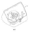
- Fig. 5 is a top plan view of an ice manipulation reservoir
- Fig. 6 is a top plan view of the ice manipulation reservoir
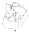
- Fig. 7 is a top plan view of the ice manipulation reservoir containing a plurality of ice pieces
- Fig. 8 is a top plan view of the ice manipulation reservoir having a plurality of blades
- Fig. 9 is a top plan view of the ice manipulation reservoir with the impeller removed from the shaft;
- Fig. 10 is a front elevational view of one embodiment of an impeller having a helical geometry
- Fig. 11 is a front elevational view of another embodiment of an impeller having a double helix geometry
- Fig. 12 is a front elevational view of another embodiment of an impeller having a shovel geometry
- Fig. 13 is a top plan view of the base of the ice manipulation reservoir
- Fig. 14A is a top plan view of the base of the ice manipulation reservoir illustrating the ice modification mechanism
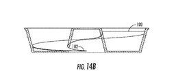
- Fig. 14B is an elevational side view of the ice manipulation reservoir illustrating a spiral descend from a first level of the base to a second level of the base;
- Fig. 15 is a front elevational view of the ice manipulation reservoir illustrating ice modification parameters
- Fig. 16A is a front elevational view of a trap door in an open position
- Fig. 16B is a front elevational view of a vertically oriented solenoid
- Fig. 16C is a front elevational view of a horizontally oriented solenoid
- Fig. 17A is a top perspective view of the base of the ice manipulation reservoir
- Fig. 17B is a side elevational view of a dispensing zone of the ice manipulation reservoir
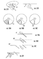
- Fig. 18A is a top plan view of the base illustrating the trap door rotated about a hinge zero degrees;
- Fig. 18B is a top plan view of the base illustrating the trap door rotated about a hinge ten degrees
- Fig. 18C is a top plan view of the base illustrating the trap door rotated about a hinge forty five degrees;
- Fig. 19A is a side elevational view of the base illustrating the trap door rotated about a hinge zero degrees;
- Fig. 19B is a side elevational view of the base illustrating the trap door rotated about a hinge ten degrees
- Fig. 19C is a side elevational view of the base illustrating the trap door rotated about a hinge forty five degrees;
- Fig. 20 is a side elevational view of a drop gap of the ice modification mechanism.
- the terms "upper,” “lower,” “right,” “left,” “rear,” “front,” “vertical,” “horizontal,” and derivatives thereof shall relate to the invention a refrigerator having a secondary cooling loop, and method thereof.
- the invention may assume various alternative orientations, except where expressly specified to the contrary.
- the specific devices and processes illustrated in the attached drawings, and described in the following specification are simply exemplary embodiments of the inventive concepts defined in the appended claims. Hence, specific dimensions and other physical characteristics relating to the embodiments disclosed herein are not to be considered as limiting, unless the claims expressly state otherwise.
- the reference number 10 generally designates an ice modification mechanism that includes an ice manipulation reservoir 12 having a base 14, wherein the base 14 includes a first level 100 and a second level 102, the first level 100 descending gradually to the second level 102.
- At least one ice modification component 70 is disposed inside the ice manipulation reservoir 12.
- the at least one ice modification component 72 is disposed substantially between the first level 100 and the second level 102 of the base 14.
- a motor 90 is operably connected with the ice manipulation reservoir 12 and includes an output shaft 92.
- An impeller 76 is connected with the output shaft 92 proximate to the at least one ice modification component 70, 72, the impeller 76 being operable between a first directional rotation A, and a second directional rotation B.
- the present invention provides an ice modification mechanism 10 for delivering ice in each of the three selected forms, namely, cubed, crushed, and shaved.
- ice cubes or bodies of ice having a three dimensional (3D) shape wherein a length in any of the dimensions is typically not less than about two centimeters (2cm).
- Shaved ice comprises bodies of ice having a three dimensional shape, in which at least one of the dimensions has a length of no greater than about five millimeters (5mm).
- Crushed ice comprises bodies of ice having a three dimensional shape, in which at least one of the dimensions has a length greater than about five millimeters (5mm), but less than about two centimeters (2cm), and no dimension has a length greater than about five centimeters (5cm).
- This ice modification mechanism 10 can be arranged within an appliance 20 such as a domestic refrigerator having a refrigerated compartment, or other types of appliances, including freezers and ice makers.
- a refrigerator 20 includes a cabinet 22 forming a freezer compartment 24 and an above-freezing refrigeration compartment 26. Both the freezer compartment 24 and the above-freezing refrigeration compartment 26 are provided with access openings 25.
- a freezer door 28 and an above-freezing door 30 are hingedly mounted to the cabinet 22 for closing the access openings 25.
- the doors 28, 30 of the appliance 20 have an exterior surface 32 and an interior surface 34 typically having a door liner 27.
- the refrigerator 20 also includes a rear wall section 36, a first side wall section 38, a second side wall section 40, a top 42, and a bottom 44. Although a side by side refrigerator is shown, it will be understood that the invention is not limited to such an arrangement.
- An ice maker 50 is disposed within the freezer compartment 24.
- the ice maker 50 is an ice piece making apparatus which forms ice pieces, typically crescent shaped, although other shapes are conceivable.
- Such an ice maker 50 is taught in U.S. Patent No. 7,278,275 entitled, "MECHANISM FOR DISPENSING SHAVED ICE FROM A REFRIGERATION APPLIANCE".
- ice in the form of cubes, which may have been made in the ice maker 50 disposed within the appliance 20 that the ice modification mechanism 10 is located within, is dispensed from the ice maker 50 to an ice manipulation reservoir 12.
- the ice may be transported to the ice manipulation reservoir 12 from the ice maker 50 by gravity or some other known delivering mechanism.
- the ice accumulates in the ice manipulation reservoir 12 until the user makes a demand for the ice.
- Known shut off mechanisms prevent ice harvesting or transfer of ice from the ice maker 50 to the ice manipulation reservoir 12 when the ice manipulation reservoir 12 is full of ice pieces. If ice harvesting is not appropriately controlled, the ice maker 50 may make an excessive quantity of ice and overflow the ice manipulation reservoir 12. In addition to limiting the quantity of ice produced, it may be desirable to prevent harvesting of ice when the freezer door 28 is open, based on the ice manipulation reservoir 12 being mounted to the door 28. If ice pieces are discharged when the door 28 is open, the ice pieces will fall onto the floor.
- the appliance 20 includes components such as those described in U.S. Patent No. 6,050,097 entitled, "ICE MAKING AND STORAGE SYSTEM FOR A REFRIGERATOR".
- the ice manipulation reservoir 12 mounted to the freezer door 28 is typically provided below the ice maker 50 for receiving ice pieces therefrom in a substantially vertical transfer, however, a substantially horizontal transfer of ice pieces from the ice maker 50 to the ice manipulation reservoir 12 is conceivable ( Figs. 3A and 3B ).
- the ice manipulation reservoir 12 includes a base 14 and at least one side wall 16.
- the side wall(s) 16 may form a cylindrical reservoir or another geometrically shaped reservoir.
- the user may prompt dispensing via a user interface 62 and/or a control mechanism 64 (not shown) arranged to effect dispensing ice from the ice manipulation reservoir 12 to the dispensing zone 60.
- the user interface 62 and the control mechanism 64 also allow the user to selectively control the form of preferred ice to be dispensed. Specifically, the user may select dispensing of ice cubes, crushed ice, or shaved ice, either singularly or in combination.
- Figs. 4-9 The capability to provide at least three forms of ice in a single well or ice manipulation reservoir 12 is illustrated in Figs. 4-9 .
- a first ice modification member or a crushing blade 70 Positioned within the ice manipulation reservoir 12 is a first ice modification member or a crushing blade 70, as well as a second ice modification member or a shaving blade 72.
- the crushing blade 70 and the shaving blade 72 are located proximate the base 14 of the ice manipulation reservoir 12.
- the blades 70, 72 may be formed as one piece or may be completely separated.
- the illustrated examples show attachment of the blades 70, 72 to the base 14, but they may also be placed proximate, yet not attached, to the base 14, such that they are positioned to perform their crushing and shaving functions.
- the base 14 of the ice manipulation reservoir 12 also includes an integrally formed trap door 80 or provides an operable connection to the trap door 80.
- the blades 70, 72 are positioned such that a leading edge 74 of each blade 70, 72 is configured to modify ice upon interaction with the ice pieces.
- Disposed within the ice manipulation reservoir 12 is an impeller 76 that assists in facilitating the interaction of the ice pieces with the blades 70, 72. Specifically, the impeller 76 pushes the ice over the crushing or shaving blade 70, 72.
- the impeller 76 may have a variety of geometric configurations, including, but not limited to, a shovel type shape 77, a single helical shape 78, or a multiple helical shape 79 ( Figs. 10-12 ).
- the shovel type shape 77 is similar to a shovel blade.
- the shovel type shape 77 may include slight arcuate angles, but a substantially level blade may be employed.
- the substantially symmetrical shape allows for efficient ice manipulation in two directions.
- the helical embodiments function differently when the impeller 76 is rotated in opposite directions. This may be advantageous, depending upon the reservoir 12 geometry or function desired.
- the impeller 76 is driven by a motor 90 located within the appliance 20.
- the impeller 76 and the motor 90 may be connected directly or via an output shaft 92 that extends between the motor 90 and the impeller 76. This connection provides the impeller 76 the ability to rotate in two directions.
- the motor 90 rotates the impeller 76 in a first direction A and the geometry of the impeller 76 pushes the ice pieces in the first direction A, while simultaneously applying a downward force. This motion initiates the interaction of the ice pieces with the leading edge 74 of the crushing blade 70, thereby modifying the ice pieces to crushed ice, as previously defined.
- the motor 90 turns the impeller 76 in a second direction B and the geometry of the impeller 76 pushes the ice pieces in the second direction B, while simultaneously applying a downward force ( Figs. 13 and 14 ). This motion initiates interaction of the ice pieces with the leading edge 74 of the shaving blade 72, thereby modifying the ice pieces to shaved ice, as previously defined.
- the crushing blade 70 has a larger volume than that of the shaving blade 72, based on the need to protrude deeper into ice pieces to effectively perform the crushing function.
- the shaving blade 72 may only protrude slightly into the ice pieces, whereas too deep of a protrusion would result in an ice form not meeting the shaved ice parameter limitations as previously defined.
- the base 14 of the ice manipulation reservoir 12 descends from a base first level 100 to a base second level 102, as opposed to having a horizontally level base.
- a non-level base 14 allows for the accommodation of a larger crushing blade 70 to be placed at a position of the base 14 with a deeper or lower level than that of the shaving blade 72 position level.
- a base 14 configuration is illustrated in Figs. 13 and 14 .
- the base 14 may descend gradually in a helical or spiral manner, as shown in Fig. 14A .
- the shaving blade 72 is positioned proximate the first level 100, with the leading blade edge 74 facing in the direction of the base 14 descending direction.
- the base 14 descends gradually until reaching a lower most second level 102.
- the crushing blade 70 is positioned proximate the second level 102, with the crushing blade 70 top edge positioned proximate the same height and/or plane of that of the shaving blade 72 top edge.
- the ice may be dispensed under the blade 70, 72, into the dispensing zone 60.
- the reservoir base 14 may accommodate the crushing blade 70 by having at least one step down from the base first level 100 to the base second level 102.
- the positioning and geometry of the blades 70, 72 are critical factors in the shaving and crushing system.
- the physics behind such a system is illustrated in Fig. 15 .
- the blade height (I) determines the thickness of the crushed piece, such that the greater the blade height, the thicker the crushed piece. Testing has determined that shaved ice is effectively produced with a blade height (I) of approximately two millimeters (2mm), while crushed ice is effectively produced with a blade height (I) of approximately seven to nine millimeters (7-9mm).
- the drop gap (D) regulates the piece size. Such regulation is accomplished based on the fact that no piece larger than the drop gap (D) may be dispensed to the user.
- Shaved ice will typically have a drop gap (D) of approximately six millimeters (6mm), when used in conjunction with the aforementioned two millimeter (2mm) blade, while crushed ice may require a drop gap (D) of approximately fourteen to eighteen millimeters (14-18mm).
- An impeller gap (H) defines the minimum ice height available to push the ice around the ice manipulation reservoir 12.
- the base 14 also includes the trap door 80 that allows for the dispensing of ice.
- the trap door 80 will lead to the dispensing zone 60, such as a chute 68.
- the trap door 80 may be hingedly attached about a substantially vertical or a substantially horizontal axis. During the crushing or shaving mode, the trap door 80 remains in a closed position, whereas the trap door 80 is opened during dispensing of ice in a cubed form.
- a solenoid or some other mechanical or electromechanical device 104 may be used to open the trap door 80, as controlled by the user interface 62 and/or the control mechanism 64.
- the ability of the motor 90 to drive the impeller 76 in at least two speeds, as well as in two directions A and B, provides the capability to produce at least three forms of ice in the single ice manipulation reservoir 12.
- the two directional capability forces an interaction with the ice pieces and the blades 70, 72.
- the direction of rotation determines whether the ice pieces are modified into crushed or shaved ice. This interaction only forces the modification of the ice pieces when the impeller 76 is driven by the motor 90 at a rate of speed X, which is greater than another speed Y.
- the lower speed Y pushes the ice around the ice manipulation reservoir 12 at a lower speed Y, thereby avoiding shaving or crushing.
- the trap door 80 will open and the ice pieces are rotated at the lower speed Y. During this motion, ice cubes are dispensed to the user.
- the impeller 76 is rotated at the higher speed X, the ice pieces are modified into shaved or crushed ice and dispensed to the user via an appropriate drop gap (D), the dimensions of which were previously defined.
- the present invention further provides a method of making the ice modification mechanism 10.
- the method involves providing the ice manipulation reservoir 12 and forming a first level 100 and a second level 102 in the base 14, the dimensions of which are dependent on the blade sizes 70, 72 that must be accommodated.
- a motor 90 having the ability to drive an impeller 76 is installed.
- the impeller 76 may be directly connected to the motor 90 or operably connected via one or more output shafts. Appropriate positioning of the impeller 76 in the ice manipulation reservoir 12 provides the ability to manipulate the ice pieces, as desired.
- the present invention provides the ability to dispense three forms of ice to a user from a single source. This ability improves on issues of spatial restraints within appliances.
Landscapes
- Engineering & Computer Science (AREA)
- Physics & Mathematics (AREA)
- Mechanical Engineering (AREA)
- Thermal Sciences (AREA)
- General Engineering & Computer Science (AREA)
- Confectionery (AREA)
- Mixers Of The Rotary Stirring Type (AREA)
- Structures Of Non-Positive Displacement Pumps (AREA)
- Toys (AREA)
- Production, Working, Storing, Or Distribution Of Ice (AREA)
Priority Applications (1)
| Application Number | Priority Date | Filing Date | Title |
|---|---|---|---|
| PL10193790T PL2333462T3 (pl) | 2009-12-14 | 2010-12-06 | Trzy postacie lodu z pojedynczego wgłębienia |
Applications Claiming Priority (1)
| Application Number | Priority Date | Filing Date | Title |
|---|---|---|---|
| US12/636,905 US20110138836A1 (en) | 2009-12-14 | 2009-12-14 | Three functions in a single well |
Publications (3)
| Publication Number | Publication Date |
|---|---|
| EP2333462A2 true EP2333462A2 (de) | 2011-06-15 |
| EP2333462A3 EP2333462A3 (de) | 2015-04-01 |
| EP2333462B1 EP2333462B1 (de) | 2017-02-01 |
Family
ID=43821956
Family Applications (1)
| Application Number | Title | Priority Date | Filing Date |
|---|---|---|---|
| EP10193790.2A Not-in-force EP2333462B1 (de) | 2009-12-14 | 2010-12-06 | Drei Eissorte aus einem einzelnen Quelle |
Country Status (4)
| Country | Link |
|---|---|
| US (1) | US20110138836A1 (de) |
| EP (1) | EP2333462B1 (de) |
| BR (1) | BRPI1005592A2 (de) |
| PL (1) | PL2333462T3 (de) |
Cited By (3)
| Publication number | Priority date | Publication date | Assignee | Title |
|---|---|---|---|---|
| CN103925757A (zh) * | 2014-05-06 | 2014-07-16 | 合肥晶弘电器有限公司 | 一种冰箱用刨冰装置及具有该刨冰装置的冰箱 |
| CN105402970A (zh) * | 2015-12-08 | 2016-03-16 | 合肥华凌股份有限公司 | 冰箱门上制冰系统 |
| CN105546899A (zh) * | 2016-01-29 | 2016-05-04 | 合肥华凌股份有限公司 | 一种冰箱自动制冰机用选冰桶及制冰机 |
Families Citing this family (3)
| Publication number | Priority date | Publication date | Assignee | Title |
|---|---|---|---|---|
| US9212840B2 (en) * | 2010-06-21 | 2015-12-15 | General Electric Company | Apparatus for pelletizing ice within a refrigerator |
| US8955350B2 (en) * | 2012-05-18 | 2015-02-17 | General Electric Company | Ice dispenser with crusher and shaver for a refrigerator appliance |
| CN104329844B (zh) * | 2014-05-21 | 2017-01-11 | 青岛海尔股份有限公司 | 刨冰机 |
Citations (2)
| Publication number | Priority date | Publication date | Assignee | Title |
|---|---|---|---|---|
| US6050097A (en) | 1998-12-28 | 2000-04-18 | Whirlpool Corporation | Ice making and storage system for a refrigerator |
| US7278275B2 (en) | 2005-03-15 | 2007-10-09 | Whirlpool Corporation | Mechanism for dispensing shaved ice from a refrigeration appliance |
Family Cites Families (21)
| Publication number | Priority date | Publication date | Assignee | Title |
|---|---|---|---|---|
| US3602441A (en) * | 1970-02-20 | 1971-08-31 | Gen Electric | Combination ice cube and crushed ice dispenser |
| US3824805A (en) * | 1973-04-09 | 1974-07-23 | Gen Electric | Combination ice cube and crushed ice dispenser selector means |
| US3889888A (en) * | 1973-04-09 | 1975-06-17 | Gen Electric | Combination ice cube and crushed ice dispenser |
| US4972999A (en) * | 1990-01-02 | 1990-11-27 | Amana Refrigeration, Inc. | Ice piece barrier for selective ice crusher dispenser |
| US5056688A (en) * | 1990-01-02 | 1991-10-15 | Amana Refrigeration Inc. | Ice cube and crushed ice dispenser |
| US6109476A (en) * | 1998-07-30 | 2000-08-29 | Maytag Corporation | Ice dispensing system |
| KR20040074856A (ko) * | 2003-02-19 | 2004-08-26 | 엘지전자 주식회사 | 냉장고의 얼음 분쇄장치 |
| EP1491833A1 (de) * | 2003-06-25 | 2004-12-29 | Lg Electronics Inc. | Eisspeicher für einen Eiserzeuger eines Kühlschrankes |
| KR20060027146A (ko) * | 2004-09-22 | 2006-03-27 | 삼성전자주식회사 | 가루얼음공급장치를 구비하는 냉장고 |
| US7340905B2 (en) * | 2004-09-30 | 2008-03-11 | Samsung Electronics Co., Ltd. | Refrigerator and method of making shaved ice |
| KR100704480B1 (ko) * | 2005-01-06 | 2007-04-10 | 엘지전자 주식회사 | 냉장고의 얼음 분쇄장치 |
| JP4152958B2 (ja) * | 2005-02-01 | 2008-09-17 | サンデン株式会社 | 飲料自動販売機の氷削機 |
| KR100690671B1 (ko) * | 2005-03-11 | 2007-03-09 | 엘지전자 주식회사 | 냉장고의 아이스빈 |
| KR100748520B1 (ko) * | 2005-03-14 | 2007-08-13 | 엘지전자 주식회사 | 개방형 아이스빈의 셔터 개폐구조 |
| JP4195473B2 (ja) * | 2005-05-03 | 2008-12-10 | 三星電子株式会社 | 冷蔵庫 |
| KR20060125302A (ko) * | 2005-06-02 | 2006-12-06 | 삼성전자주식회사 | 냉장고 |
| KR101120325B1 (ko) * | 2005-08-18 | 2012-03-08 | 엘지전자 주식회사 | 아바타 냉장고 |
| US7395672B2 (en) * | 2005-10-18 | 2008-07-08 | General Electric Company | Ice dispenser assembly and method of assembling same |
| KR100719024B1 (ko) * | 2005-11-14 | 2007-05-17 | 삼성전자주식회사 | 냉장고 및 그 제어방법 |
| KR101275206B1 (ko) * | 2006-03-14 | 2013-06-18 | 엘지전자 주식회사 | 제빙장치 |
| KR100781269B1 (ko) * | 2006-12-31 | 2007-11-30 | 엘지전자 주식회사 | 얼음배출장치 |
-
2009
- 2009-12-14 US US12/636,905 patent/US20110138836A1/en not_active Abandoned
-
2010
- 2010-12-06 PL PL10193790T patent/PL2333462T3/pl unknown
- 2010-12-06 EP EP10193790.2A patent/EP2333462B1/de not_active Not-in-force
- 2010-12-13 BR BRPI1005592-4A patent/BRPI1005592A2/pt not_active IP Right Cessation
Patent Citations (2)
| Publication number | Priority date | Publication date | Assignee | Title |
|---|---|---|---|---|
| US6050097A (en) | 1998-12-28 | 2000-04-18 | Whirlpool Corporation | Ice making and storage system for a refrigerator |
| US7278275B2 (en) | 2005-03-15 | 2007-10-09 | Whirlpool Corporation | Mechanism for dispensing shaved ice from a refrigeration appliance |
Cited By (4)
| Publication number | Priority date | Publication date | Assignee | Title |
|---|---|---|---|---|
| CN103925757A (zh) * | 2014-05-06 | 2014-07-16 | 合肥晶弘电器有限公司 | 一种冰箱用刨冰装置及具有该刨冰装置的冰箱 |
| CN105402970A (zh) * | 2015-12-08 | 2016-03-16 | 合肥华凌股份有限公司 | 冰箱门上制冰系统 |
| CN105402970B (zh) * | 2015-12-08 | 2018-03-16 | 合肥华凌股份有限公司 | 冰箱门上制冰系统 |
| CN105546899A (zh) * | 2016-01-29 | 2016-05-04 | 合肥华凌股份有限公司 | 一种冰箱自动制冰机用选冰桶及制冰机 |
Also Published As
| Publication number | Publication date |
|---|---|
| EP2333462A3 (de) | 2015-04-01 |
| US20110138836A1 (en) | 2011-06-16 |
| BRPI1005592A2 (pt) | 2015-08-25 |
| EP2333462B1 (de) | 2017-02-01 |
| PL2333462T3 (pl) | 2017-06-30 |
Similar Documents
| Publication | Publication Date | Title |
|---|---|---|
| US10006689B2 (en) | Modular bucket and door architecture to deliver three ice functions | |
| EP2674702B1 (de) | Kühlschrank | |
| US6880355B2 (en) | Refrigerator with ice feeding unit | |
| EP2333462B1 (de) | Drei Eissorte aus einem einzelnen Quelle | |
| EP2679939B1 (de) | Kühlschrank | |
| US7278275B2 (en) | Mechanism for dispensing shaved ice from a refrigeration appliance | |
| EP1930672B1 (de) | Kühlschrank mit verbesserter Gestaltung des Eiserzeugungsteils | |
| KR102465860B1 (ko) | 냉장고 | |
| CN1752676A (zh) | 具有刨冰供给装置的电冰箱 | |
| US8955350B2 (en) | Ice dispenser with crusher and shaver for a refrigerator appliance | |
| MXPA04003411A (es) | Dispositivo para la fabricacion de hielos en gabinetes refrigerados. | |
| WO2008054161A2 (en) | Refrigerator and apparatus for ice discharging therein | |
| US20060065008A1 (en) | Refrigerator | |
| KR20060125302A (ko) | 냉장고 | |
| EP1722178A2 (de) | Eisausgabegerät und Kühlschrank mit einem solchen Gerät | |
| US7360377B2 (en) | Refrigerator | |
| EP2021706B1 (de) | Kühlvorrichtung | |
| US9903632B2 (en) | Ice well diverter wedge for ice container | |
| CN100337078C (zh) | 电冰箱 | |
| KR101069475B1 (ko) | 아이스 버킷 및 이를 구비한 냉장고 | |
| KR102640322B1 (ko) | 제빙기 및 이를 포함하는 냉장고 | |
| WO2008082194A1 (en) | Device for ice discharging | |
| US20250290679A1 (en) | Twist ice tray assembly for a refrigerator appliance | |
| US7765828B2 (en) | Method and apparatus for forming asymmetrical ice cubes | |
| KR100565620B1 (ko) | 냉장고용 제빙장치의 아이스뱅크 |
Legal Events
| Date | Code | Title | Description |
|---|---|---|---|
| PUAI | Public reference made under article 153(3) epc to a published international application that has entered the european phase |
Free format text: ORIGINAL CODE: 0009012 |
|
| AK | Designated contracting states |
Kind code of ref document: A2 Designated state(s): AL AT BE BG CH CY CZ DE DK EE ES FI FR GB GR HR HU IE IS IT LI LT LU LV MC MK MT NL NO PL PT RO RS SE SI SK SM TR |
|
| AX | Request for extension of the european patent |
Extension state: BA ME |
|
| PUAL | Search report despatched |
Free format text: ORIGINAL CODE: 0009013 |
|
| AK | Designated contracting states |
Kind code of ref document: A3 Designated state(s): AL AT BE BG CH CY CZ DE DK EE ES FI FR GB GR HR HU IE IS IT LI LT LU LV MC MK MT NL NO PL PT RO RS SE SI SK SM TR |
|
| AX | Request for extension of the european patent |
Extension state: BA ME |
|
| RIC1 | Information provided on ipc code assigned before grant |
Ipc: F25C 5/04 20060101AFI20150223BHEP Ipc: F25C 5/02 20060101ALN20150223BHEP Ipc: F25C 5/00 20060101ALI20150223BHEP Ipc: F25C 5/12 20060101ALN20150223BHEP |
|
| 17P | Request for examination filed |
Effective date: 20150930 |
|
| RBV | Designated contracting states (corrected) |
Designated state(s): AL AT BE BG CH CY CZ DE DK EE ES FI FR GB GR HR HU IE IS IT LI LT LU LV MC MK MT NL NO PL PT RO RS SE SI SK SM TR |
|
| 17Q | First examination report despatched |
Effective date: 20151214 |
|
| RIC1 | Information provided on ipc code assigned before grant |
Ipc: F25C 5/04 20060101AFI20160908BHEP Ipc: F25C 5/12 20060101ALI20160908BHEP |
|
| GRAP | Despatch of communication of intention to grant a patent |
Free format text: ORIGINAL CODE: EPIDOSNIGR1 |
|
| INTG | Intention to grant announced |
Effective date: 20161107 |
|
| GRAS | Grant fee paid |
Free format text: ORIGINAL CODE: EPIDOSNIGR3 |
|
| GRAA | (expected) grant |
Free format text: ORIGINAL CODE: 0009210 |
|
| AK | Designated contracting states |
Kind code of ref document: B1 Designated state(s): AL AT BE BG CH CY CZ DE DK EE ES FI FR GB GR HR HU IE IS IT LI LT LU LV MC MK MT NL NO PL PT RO RS SE SI SK SM TR |
|
| REG | Reference to a national code |
Ref country code: GB Ref legal event code: FG4D |
|
| REG | Reference to a national code |
Ref country code: CH Ref legal event code: EP Ref country code: AT Ref legal event code: REF Ref document number: 865931 Country of ref document: AT Kind code of ref document: T Effective date: 20170215 |
|
| REG | Reference to a national code |
Ref country code: IE Ref legal event code: FG4D |
|
| REG | Reference to a national code |
Ref country code: DE Ref legal event code: R096 Ref document number: 602010039917 Country of ref document: DE |
|
| REG | Reference to a national code |
Ref country code: NL Ref legal event code: MP Effective date: 20170201 |
|
| REG | Reference to a national code |
Ref country code: LT Ref legal event code: MG4D |
|
| REG | Reference to a national code |
Ref country code: AT Ref legal event code: MK05 Ref document number: 865931 Country of ref document: AT Kind code of ref document: T Effective date: 20170201 |
|
| PG25 | Lapsed in a contracting state [announced via postgrant information from national office to epo] |
Ref country code: LT Free format text: LAPSE BECAUSE OF FAILURE TO SUBMIT A TRANSLATION OF THE DESCRIPTION OR TO PAY THE FEE WITHIN THE PRESCRIBED TIME-LIMIT Effective date: 20170201 Ref country code: IS Free format text: LAPSE BECAUSE OF FAILURE TO SUBMIT A TRANSLATION OF THE DESCRIPTION OR TO PAY THE FEE WITHIN THE PRESCRIBED TIME-LIMIT Effective date: 20170601 Ref country code: GR Free format text: LAPSE BECAUSE OF FAILURE TO SUBMIT A TRANSLATION OF THE DESCRIPTION OR TO PAY THE FEE WITHIN THE PRESCRIBED TIME-LIMIT Effective date: 20170502 Ref country code: FI Free format text: LAPSE BECAUSE OF FAILURE TO SUBMIT A TRANSLATION OF THE DESCRIPTION OR TO PAY THE FEE WITHIN THE PRESCRIBED TIME-LIMIT Effective date: 20170201 Ref country code: HR Free format text: LAPSE BECAUSE OF FAILURE TO SUBMIT A TRANSLATION OF THE DESCRIPTION OR TO PAY THE FEE WITHIN THE PRESCRIBED TIME-LIMIT Effective date: 20170201 Ref country code: NO Free format text: LAPSE BECAUSE OF FAILURE TO SUBMIT A TRANSLATION OF THE DESCRIPTION OR TO PAY THE FEE WITHIN THE PRESCRIBED TIME-LIMIT Effective date: 20170501 |
|
| PG25 | Lapsed in a contracting state [announced via postgrant information from national office to epo] |
Ref country code: AT Free format text: LAPSE BECAUSE OF FAILURE TO SUBMIT A TRANSLATION OF THE DESCRIPTION OR TO PAY THE FEE WITHIN THE PRESCRIBED TIME-LIMIT Effective date: 20170201 Ref country code: RS Free format text: LAPSE BECAUSE OF FAILURE TO SUBMIT A TRANSLATION OF THE DESCRIPTION OR TO PAY THE FEE WITHIN THE PRESCRIBED TIME-LIMIT Effective date: 20170201 Ref country code: SE Free format text: LAPSE BECAUSE OF FAILURE TO SUBMIT A TRANSLATION OF THE DESCRIPTION OR TO PAY THE FEE WITHIN THE PRESCRIBED TIME-LIMIT Effective date: 20170201 Ref country code: NL Free format text: LAPSE BECAUSE OF FAILURE TO SUBMIT A TRANSLATION OF THE DESCRIPTION OR TO PAY THE FEE WITHIN THE PRESCRIBED TIME-LIMIT Effective date: 20170201 Ref country code: PT Free format text: LAPSE BECAUSE OF FAILURE TO SUBMIT A TRANSLATION OF THE DESCRIPTION OR TO PAY THE FEE WITHIN THE PRESCRIBED TIME-LIMIT Effective date: 20170601 Ref country code: LV Free format text: LAPSE BECAUSE OF FAILURE TO SUBMIT A TRANSLATION OF THE DESCRIPTION OR TO PAY THE FEE WITHIN THE PRESCRIBED TIME-LIMIT Effective date: 20170201 Ref country code: ES Free format text: LAPSE BECAUSE OF FAILURE TO SUBMIT A TRANSLATION OF THE DESCRIPTION OR TO PAY THE FEE WITHIN THE PRESCRIBED TIME-LIMIT Effective date: 20170201 Ref country code: BG Free format text: LAPSE BECAUSE OF FAILURE TO SUBMIT A TRANSLATION OF THE DESCRIPTION OR TO PAY THE FEE WITHIN THE PRESCRIBED TIME-LIMIT Effective date: 20170501 |
|
| PG25 | Lapsed in a contracting state [announced via postgrant information from national office to epo] |
Ref country code: RO Free format text: LAPSE BECAUSE OF FAILURE TO SUBMIT A TRANSLATION OF THE DESCRIPTION OR TO PAY THE FEE WITHIN THE PRESCRIBED TIME-LIMIT Effective date: 20170201 Ref country code: EE Free format text: LAPSE BECAUSE OF FAILURE TO SUBMIT A TRANSLATION OF THE DESCRIPTION OR TO PAY THE FEE WITHIN THE PRESCRIBED TIME-LIMIT Effective date: 20170201 Ref country code: CZ Free format text: LAPSE BECAUSE OF FAILURE TO SUBMIT A TRANSLATION OF THE DESCRIPTION OR TO PAY THE FEE WITHIN THE PRESCRIBED TIME-LIMIT Effective date: 20170201 Ref country code: SK Free format text: LAPSE BECAUSE OF FAILURE TO SUBMIT A TRANSLATION OF THE DESCRIPTION OR TO PAY THE FEE WITHIN THE PRESCRIBED TIME-LIMIT Effective date: 20170201 |
|
| REG | Reference to a national code |
Ref country code: DE Ref legal event code: R097 Ref document number: 602010039917 Country of ref document: DE |
|
| REG | Reference to a national code |
Ref country code: FR Ref legal event code: PLFP Year of fee payment: 8 |
|
| PG25 | Lapsed in a contracting state [announced via postgrant information from national office to epo] |
Ref country code: DK Free format text: LAPSE BECAUSE OF FAILURE TO SUBMIT A TRANSLATION OF THE DESCRIPTION OR TO PAY THE FEE WITHIN THE PRESCRIBED TIME-LIMIT Effective date: 20170201 Ref country code: SM Free format text: LAPSE BECAUSE OF FAILURE TO SUBMIT A TRANSLATION OF THE DESCRIPTION OR TO PAY THE FEE WITHIN THE PRESCRIBED TIME-LIMIT Effective date: 20170201 |
|
| PLBE | No opposition filed within time limit |
Free format text: ORIGINAL CODE: 0009261 |
|
| STAA | Information on the status of an ep patent application or granted ep patent |
Free format text: STATUS: NO OPPOSITION FILED WITHIN TIME LIMIT |
|
| 26N | No opposition filed |
Effective date: 20171103 |
|
| PGFP | Annual fee paid to national office [announced via postgrant information from national office to epo] |
Ref country code: FR Payment date: 20171113 Year of fee payment: 8 Ref country code: DE Payment date: 20171129 Year of fee payment: 8 |
|
| PG25 | Lapsed in a contracting state [announced via postgrant information from national office to epo] |
Ref country code: SI Free format text: LAPSE BECAUSE OF FAILURE TO SUBMIT A TRANSLATION OF THE DESCRIPTION OR TO PAY THE FEE WITHIN THE PRESCRIBED TIME-LIMIT Effective date: 20170201 |
|
| PGFP | Annual fee paid to national office [announced via postgrant information from national office to epo] |
Ref country code: GB Payment date: 20171206 Year of fee payment: 8 |
|
| PGFP | Annual fee paid to national office [announced via postgrant information from national office to epo] |
Ref country code: IT Payment date: 20171221 Year of fee payment: 8 |
|
| REG | Reference to a national code |
Ref country code: CH Ref legal event code: PL |
|
| REG | Reference to a national code |
Ref country code: IE Ref legal event code: MM4A |
|
| PG25 | Lapsed in a contracting state [announced via postgrant information from national office to epo] |
Ref country code: LU Free format text: LAPSE BECAUSE OF NON-PAYMENT OF DUE FEES Effective date: 20171206 Ref country code: MT Free format text: LAPSE BECAUSE OF NON-PAYMENT OF DUE FEES Effective date: 20171206 |
|
| REG | Reference to a national code |
Ref country code: BE Ref legal event code: MM Effective date: 20171231 |
|
| PG25 | Lapsed in a contracting state [announced via postgrant information from national office to epo] |
Ref country code: IE Free format text: LAPSE BECAUSE OF NON-PAYMENT OF DUE FEES Effective date: 20171206 |
|
| PG25 | Lapsed in a contracting state [announced via postgrant information from national office to epo] |
Ref country code: CH Free format text: LAPSE BECAUSE OF NON-PAYMENT OF DUE FEES Effective date: 20171231 Ref country code: LI Free format text: LAPSE BECAUSE OF NON-PAYMENT OF DUE FEES Effective date: 20171231 Ref country code: BE Free format text: LAPSE BECAUSE OF NON-PAYMENT OF DUE FEES Effective date: 20171231 |
|
| PG25 | Lapsed in a contracting state [announced via postgrant information from national office to epo] |
Ref country code: PL Free format text: LAPSE BECAUSE OF NON-PAYMENT OF DUE FEES Effective date: 20171206 |
|
| PG25 | Lapsed in a contracting state [announced via postgrant information from national office to epo] |
Ref country code: HU Free format text: LAPSE BECAUSE OF FAILURE TO SUBMIT A TRANSLATION OF THE DESCRIPTION OR TO PAY THE FEE WITHIN THE PRESCRIBED TIME-LIMIT; INVALID AB INITIO Effective date: 20101206 Ref country code: MC Free format text: LAPSE BECAUSE OF FAILURE TO SUBMIT A TRANSLATION OF THE DESCRIPTION OR TO PAY THE FEE WITHIN THE PRESCRIBED TIME-LIMIT Effective date: 20170201 |
|
| REG | Reference to a national code |
Ref country code: DE Ref legal event code: R119 Ref document number: 602010039917 Country of ref document: DE |
|
| GBPC | Gb: european patent ceased through non-payment of renewal fee |
Effective date: 20181206 |
|
| PG25 | Lapsed in a contracting state [announced via postgrant information from national office to epo] |
Ref country code: IT Free format text: LAPSE BECAUSE OF NON-PAYMENT OF DUE FEES Effective date: 20181206 Ref country code: CY Free format text: LAPSE BECAUSE OF NON-PAYMENT OF DUE FEES Effective date: 20170201 Ref country code: FR Free format text: LAPSE BECAUSE OF NON-PAYMENT OF DUE FEES Effective date: 20181231 Ref country code: DE Free format text: LAPSE BECAUSE OF NON-PAYMENT OF DUE FEES Effective date: 20190702 |
|
| PG25 | Lapsed in a contracting state [announced via postgrant information from national office to epo] |
Ref country code: MK Free format text: LAPSE BECAUSE OF FAILURE TO SUBMIT A TRANSLATION OF THE DESCRIPTION OR TO PAY THE FEE WITHIN THE PRESCRIBED TIME-LIMIT Effective date: 20170201 |
|
| PG25 | Lapsed in a contracting state [announced via postgrant information from national office to epo] |
Ref country code: GB Free format text: LAPSE BECAUSE OF NON-PAYMENT OF DUE FEES Effective date: 20181206 |
|
| PG25 | Lapsed in a contracting state [announced via postgrant information from national office to epo] |
Ref country code: TR Free format text: LAPSE BECAUSE OF FAILURE TO SUBMIT A TRANSLATION OF THE DESCRIPTION OR TO PAY THE FEE WITHIN THE PRESCRIBED TIME-LIMIT Effective date: 20170201 |
|
| PG25 | Lapsed in a contracting state [announced via postgrant information from national office to epo] |
Ref country code: AL Free format text: LAPSE BECAUSE OF FAILURE TO SUBMIT A TRANSLATION OF THE DESCRIPTION OR TO PAY THE FEE WITHIN THE PRESCRIBED TIME-LIMIT Effective date: 20170201 |