EP2333436A2 - Supply air unit and method in ventilation - Google Patents
Supply air unit and method in ventilation Download PDFInfo
- Publication number
- EP2333436A2 EP2333436A2 EP10189926A EP10189926A EP2333436A2 EP 2333436 A2 EP2333436 A2 EP 2333436A2 EP 10189926 A EP10189926 A EP 10189926A EP 10189926 A EP10189926 A EP 10189926A EP 2333436 A2 EP2333436 A2 EP 2333436A2
- Authority
- EP
- European Patent Office
- Prior art keywords
- supply air
- chamber
- airflow
- distribution
- heat exchanger
- Prior art date
- Legal status (The legal status is an assumption and is not a legal conclusion. Google has not performed a legal analysis and makes no representation as to the accuracy of the status listed.)
- Pending
Links
Images



Classifications
-
- F—MECHANICAL ENGINEERING; LIGHTING; HEATING; WEAPONS; BLASTING
- F24—HEATING; RANGES; VENTILATING
- F24F—AIR-CONDITIONING; AIR-HUMIDIFICATION; VENTILATION; USE OF AIR CURRENTS FOR SCREENING
- F24F1/00—Room units for air-conditioning, e.g. separate or self-contained units or units receiving primary air from a central station
- F24F1/01—Room units for air-conditioning, e.g. separate or self-contained units or units receiving primary air from a central station in which secondary air is induced by injector action of the primary air
-
- F—MECHANICAL ENGINEERING; LIGHTING; HEATING; WEAPONS; BLASTING
- F24—HEATING; RANGES; VENTILATING
- F24F—AIR-CONDITIONING; AIR-HUMIDIFICATION; VENTILATION; USE OF AIR CURRENTS FOR SCREENING
- F24F1/00—Room units for air-conditioning, e.g. separate or self-contained units or units receiving primary air from a central station
- F24F1/0007—Indoor units, e.g. fan coil units
- F24F1/0043—Indoor units, e.g. fan coil units characterised by mounting arrangements
- F24F1/0047—Indoor units, e.g. fan coil units characterised by mounting arrangements mounted in the ceiling or at the ceiling
-
- F—MECHANICAL ENGINEERING; LIGHTING; HEATING; WEAPONS; BLASTING
- F24—HEATING; RANGES; VENTILATING
- F24F—AIR-CONDITIONING; AIR-HUMIDIFICATION; VENTILATION; USE OF AIR CURRENTS FOR SCREENING
- F24F1/00—Room units for air-conditioning, e.g. separate or self-contained units or units receiving primary air from a central station
- F24F1/0007—Indoor units, e.g. fan coil units
- F24F1/0011—Indoor units, e.g. fan coil units characterised by air outlets
-
- F—MECHANICAL ENGINEERING; LIGHTING; HEATING; WEAPONS; BLASTING
- F24—HEATING; RANGES; VENTILATING
- F24F—AIR-CONDITIONING; AIR-HUMIDIFICATION; VENTILATION; USE OF AIR CURRENTS FOR SCREENING
- F24F1/00—Room units for air-conditioning, e.g. separate or self-contained units or units receiving primary air from a central station
- F24F1/0007—Indoor units, e.g. fan coil units
- F24F1/0059—Indoor units, e.g. fan coil units characterised by heat exchangers
- F24F1/0063—Indoor units, e.g. fan coil units characterised by heat exchangers by the mounting or arrangement of the heat exchangers
Definitions
- the invention concerns a supply air unit in accordance with the preamble to claim 1.
- the invention also concerns a method in ventilation in accordance with the preamble to claim 3.
- Supply air units or air-conditioning beams comprise a supply air chamber, a mixing chamber and a heat exchanger.
- a flow of fresh air is brought from the supply air chamber into the mixing chamber, in which the fresh airflow is mixed with a circulated airflow, whereupon the combined airflow is conducted into the room space.
- the circulated airflow is conducted into the mixing chamber through the heat exchanger, in which the circulated airflow can be heated or cooled.
- the room air can be cooled in the summer time and the room air can be heated in the winter time. In the summer time, the room's circulated airflow is cooled, and in the winter time it is heated in the supply air unit's heat exchanger.
- the fresh airflow induces the circulated airflow to flow from the room through the heat exchanger into the mixing chamber.
- the problem is in the room's fringe spaces, such as the wall bordering on the outside air and having a window.
- the cold window surface causes a cold airflow downwards in the room space, and in the summer time air heated by the window surface tends to rise strongly up to the ceiling of the room space.
- An air-conditioning beam or air-conditioning beams are usually adjusted for the room's average need for cooling or heating, whereby the situation is not satisfactory in the room's fringe spaces.
- the air-conditioning beam located nearest to the window-wall can be dimensioned for a higher cooling or heating power.
- Passive air-conditioning beams have also been used close to the window-wall, whereby the air-conditioning beam sucks up the airflow directed upwards to the ceiling of the room from the window heated by the sun.
- the combined airflow can be guided into the air-conditioned room space from the supply air unit's mixing chambers, either so that the entire combined airflow is guided downwards into the air-conditioned room space or so that the entire combined airflow is guided in the direction of the ceiling in the air-conditioned room space to the side or so that a part of the combined airflow is guided downwards and a part of the combined airflow is guided in the direction of the ceiling in the air-conditioned room space to the side.
- the room conditions can be controlled so that the control takes into account the need for heating and/or cooling according to the season and the convection flow taking place from the window surface, which in the winter time is a cold airflow directed towards the floor and which in the summer time is a warm airflow directed towards the ceiling.
- the supply air unit's summer mode is used, in which a first part of the combined airflow is guided in the direction of the window-wall downwards, and a second part of the combined airflow is guided to the side in the direction of the ceiling in the room space.
- the winter mode is used, in which the combined airflow is guided in its entirety downwards in the direction of the window-wall.
- the supply air unit's spring mode is used, in which the combined airflow is guided in its entirety in the direction of the ceiling in the room space.
- the supply air unit's alignment can be controlled, for example, based on a measuring signal from a temperature sensor measuring the surface temperature of the window in the air-conditioned room space.
- the supply air unit's alignment can be controlled individually by the user.
- the user can control the supply air unit, for example, with a control device located on his work table, which control device co-operates with the window's surface temperature control and boosts the directing of the supply air jet in either direction, that is, in the direction of the ceiling or the window.
- the control can also be implemented in such a way that it is operated only by the user.
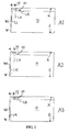
- Figure 1 shows a supply air unit in accordance with the invention in three different modes of operation A1, A2 and A3.
- a cross-section is shown of the room H to be air-conditioned, where the supply air unit 10 according to the invention can be seen.
- the supply air unit 10 is suspended from the room's H ceiling K, at a distance from the ceiling K and at a distance S 1 from the room's H window-wall W.
- the supply air unit 10 is parallel to the room's H window-wall W.
- FIG. 1 Topmost in Figure 1 the summer mode A1 of the supply air unit 10 is shown.
- the sun will heat the window W1, whereby a warm airflow LL is directed along the window surface W1 and the window-wall W upwards towards the ceiling K.
- a first airflow LA cooling the room H is hereby guided through the supply air unit 10 obliquely downwards towards the floor E, and a second airflow LB cooling the room is guided in the direction of ceiling K to the side.
- the warm airflow LL directed upwards from window W1 is guided along with the circulated airflow into the supply air unit's 10 heat exchanger, whereby said warm airflow LL cannot spread into the room space H.
- the cooling airflow LA directed towards floor E can be kept moderate, so that it will not cause any sense of draught.
- the winter mode A2 of the supply air unit 10 is shown.
- the window W1 emanates cold, which is directed as a cold airflow LK along window-wall W downwards towards floor E.
- a heating airflow LA is hereby guided through the supply air unit 10 only obliquely downwards towards floor E. In this manner the cold airflow LK directed downwards from the cold-emanating window W1 can be cut off, whereby cold is prevented from spreading along floor E into the room space H.
- FIG. 2 is an axonometric view of the supply air unit according to the invention.
- the supply air unit 10 comprises a supply air chamber 11 having a rectangular cross-section, into which a fresh airflow is conducted from outside through a duct system and a blowing fan.
- a side wall of supply air chamber 11 there are a first 12a and a second 12b flow opening, which are closed and opened by a damper 13 moving horizontally in the direction of the side wall.
- the first flow opening 12a connects a first elongated distribution chamber 14a with the supply air chamber 11, and the second flow opening 12b connects a second elongated distribution chamber 14b with the supply air chamber 11.
- the first 14a and the second 14b distribution chambers are parallel and they have a rectangular cross section.
- the damper 13 located in connection with a side wall in supply air chamber 11 is cooperative with the first 12a and the second 12b flow opening. Opening of the first flow opening 12a will close the second flow opening 12b and vice versa.
- the damper 13 is thus used to control the distribution between the distribution chambers 14a, 14b of the total fresh airflow supplied from supply air chamber 11 into the distribution chambers 14a, 14b.
- first nozzle row 16a In the bottom surface of the first distribution chamber 14a there is a first nozzle row 16a, through which fresh air can be conducted from the first distribution chamber 14a into a first mixing chamber 15a located below it.
- second nozzle row 16b there is in the bottom surface of the second distribution chamber 14b a second nozzle row 16b, through which fresh air can be conducted from the second distribution chamber 14b into a second mixing chamber 15b located below it.
- first distribution chamber 14a and the second distribution chamber 14b In between the first distribution chamber 14a and the second distribution chamber 14b an elongated heat exchanger 17 is fitted, which has a rectangular cross section. Under the heat exchanger 17 a first trapeze-shaped guiding component 18 is fitted. Under an outer side wall of the first distribution chamber 14a a vertical first side wall 19a is fitted, and under the second distribution chamber 14b a second guiding component 20 is fitted.
- first mixing chamber 15a In the lower part of the first mixing chamber 15a there is a first outlet opening 25a, from which the combined airflow formed in the first mixing chamber 15a is guided downwards towards the floor surface of the air-conditioned room space.
- second outlet opening 25b In the lower part of the second mixing chamber 15b there is a second outlet opening 25b, from which the combined airflow formed in the second mixing chamber 15b is guided to the side in the direction of the ceiling of the air-conditioned room space.
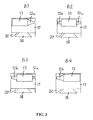
- Figure 3 is a cross-sectional view of Figure 2 showing the principle of controlling the supply air.
- the room's window-wall is here on the right side of the supply air unit.
- the damper 13 in the supply air chamber's 11 side wall is in its middle position.
- One-half of the supply air chamber's 11 fresh airflow is guided through the first flow opening 12a into the first distribution chamber 14a and the other half of the supply air chamber's 11 fresh airflow is guided through the second flow opening 12b into the second distribution chamber 14b.
- the damper 13 in the supply air chamber's 11 side wall is close to its second extreme position.
- a small part of the supply air chamber's 11 fresh airflow is guided through the first flow opening 12a into the first distribution chamber 14a, and a major part of the supply air chamber's 11 fresh airflow is guided through the second flow opening 12b into the second distribution chamber 14b.
- the flow openings 12a, 12b in the supply air chamber's 11 side wall are shaped in such a way that the total throttle in the fresh airflow conducted from supply air chamber 11 into distribution chambers 14a, 14b will remain constant all the time.
- the entire fresh airflow is guided from supply air chamber 11 through the nozzles 16a, 16b of either distribution chamber 14a, 14b into the corresponding mixing chamber 15a, 15b.
- one-half of the total number of nozzles 16a, 16b are located along the flow path of the fresh airflow, if the number of nozzles 16a, 16b is the same in each distribution chamber 14a, 14b.
- the whole number of nozzles 16a, 16b is along the flow path of the fresh airflow. This must be taken into account when designing the shape of the flow openings 12a, 12b.
- Figure 4 is a cross-sectional view of the supply air unit shown in Figure 2 .
- the room's window-wall is on the left side of supply air unit 10.
- the first mixing chamber 15 located on the left side of the supply air unit's 10 vertical central axis Y-Y is formed in a space limited by the bottom of the first distribution chamber 14a, the left side wall of heat exchanger 17, the left-hand oblique guiding surface F2 of the first guiding component 18 and the vertical first side wall 19a continuing downwards from the outer side wall of the first distribution chamber 14a.
- the second mixing chamber 15b located on the right side of the supply air unit's 10 vertical central axis Y-Y is formed in a space limited by the bottom of the second distribution chamber 14b, the right side wall of heat exchanger 17, the first guiding component's 18 right-hand oblique guiding surface F2 and the second guiding component 20 located under the second distribution chamber 14b.
- the fresh airflow L1 is guided downwards into the first mixing chamber 15a beside its left-hand vertical side wall 19a, to which the fresh airflow L1 is adhered due to the Coanda effect.
- the circulated airflow L2 arriving through heat exchanger 17 into the first mixing chamber 15a is combined with the fresh airflow L1 in the first mixing chamber 15a, and guided by the left side wall 19a and the left-hand oblique guiding surface F2 of the first guiding component 18, the combined airflow LA is directed from the first mixing chamber's 15a outlet opening 25a obliquely downwards towards the floor of the air-conditioned room space.
- the circulated airflow L2 arriving through heat exchanger 17 into the first mixing chamber 15a is combined with the fresh airflow L1 in the second mixing chamber 15b, and the combined airflow LB travels first downwards along the heat exchanger's 17 right side wall, whereupon it is guided through the channel between the first guiding component's 18 right-hand oblique guiding surface F2 and the second guiding component 20 from the second mixing chamber's 15b outlet opening 25b in a horizontal direction to the side along the ceiling of the air-conditioned room space and adhered to this under the Coanda effect.
- the circulated airflow L2 travels from the air-conditioned room space H into heat exchanger 17 and from this further into the first mixing chamber 15a located on the left side of heat exchanger 17 and into the second mixing chamber 15b located on the right side of heat exchanger 17.
- the circulated airflow L2 can be either heated or cooled in heat exchanger 17.
- the combined airflow LA discharging from the first mixing chamber 15a is guided only downwards, and the combined airflow LB discharging from the second mixing chamber 15a is guided only in a horizontal direction to the side.
- the supply air unit 10 is located in the ceiling K of the air-conditioned room space H in such a way that the supply air unit's 10 that edge, which has the first distribution chamber 14a, and the first mixing chamber 15a located under it will be located on the side of the window-wall W.
- the supply air unit 10 according to the invention can be located close to the ceiling of the room space, in the direction of the window-wall, at a distance from the window-wall or in a hotel room's false ceiling in the direction of the hotel room's door-wall, at a distance from the door-wall.
- the cross-sectional surfaces of supply air chambers 11, distribution chambers 14a, 14b and heat exchangers 17 form a rectangle.
- This is a cross-sectional shape which is advantageous in terms of manufacturing technique, but the cross-sectional shape of these devices may also be of a different kind, for example, round, a trapeze or a polygon.
Landscapes
- Engineering & Computer Science (AREA)
- Chemical & Material Sciences (AREA)
- Combustion & Propulsion (AREA)
- Mechanical Engineering (AREA)
- General Engineering & Computer Science (AREA)
- Physics & Mathematics (AREA)
- Thermal Sciences (AREA)
- Duct Arrangements (AREA)
- Central Air Conditioning (AREA)
- Heat-Exchange Devices With Radiators And Conduit Assemblies (AREA)
Abstract
Description
- The invention concerns a supply air unit in accordance with the preamble to claim 1.
- The invention also concerns a method in ventilation in accordance with the preamble to claim 3.
- Supply air units or air-conditioning beams comprise a supply air chamber, a mixing chamber and a heat exchanger. A flow of fresh air is brought from the supply air chamber into the mixing chamber, in which the fresh airflow is mixed with a circulated airflow, whereupon the combined airflow is conducted into the room space. The circulated airflow is conducted into the mixing chamber through the heat exchanger, in which the circulated airflow can be heated or cooled. With the same supply air unit the room air can be cooled in the summer time and the room air can be heated in the winter time. In the summer time, the room's circulated airflow is cooled, and in the winter time it is heated in the supply air unit's heat exchanger. The fresh airflow induces the circulated airflow to flow from the room through the heat exchanger into the mixing chamber.
- The problem is in the room's fringe spaces, such as the wall bordering on the outside air and having a window. In the winter time there is a cold draught, when the cold window surface causes a cold airflow downwards in the room space, and in the summer time air heated by the window surface tends to rise strongly up to the ceiling of the room space.
- An air-conditioning beam or air-conditioning beams are usually adjusted for the room's average need for cooling or heating, whereby the situation is not satisfactory in the room's fringe spaces. In a situation where the room has several air-conditioning beams, the air-conditioning beam located nearest to the window-wall can be dimensioned for a higher cooling or heating power. Passive air-conditioning beams have also been used close to the window-wall, whereby the air-conditioning beam sucks up the airflow directed upwards to the ceiling of the room from the window heated by the sun.
- Known solutions have not been able to solve in a satisfactory manner this above-mentioned problem relating to the room's fringe spaces.
- With the supply air unit according to the invention the above-mentioned airflows resulting from the temperature of the window surface can be better taken into account.
- The main characteristics of the air-conditioning device according to the invention are presented in the characterising part of
claim 1. - The main characteristics of the method according to the invention are presented in the characterising part of claim 3.
- With the aid of a guiding arrangement for the supply air unit according to the invention the combined airflow can be guided into the air-conditioned room space from the supply air unit's mixing chambers, either so that the entire combined airflow is guided downwards into the air-conditioned room space or so that the entire combined airflow is guided in the direction of the ceiling in the air-conditioned room space to the side or so that a part of the combined airflow is guided downwards and a part of the combined airflow is guided in the direction of the ceiling in the air-conditioned room space to the side.
- With the supply air unit according to the invention the room conditions can be controlled so that the control takes into account the need for heating and/or cooling according to the season and the convection flow taking place from the window surface, which in the winter time is a cold airflow directed towards the floor and which in the summer time is a warm airflow directed towards the ceiling.
- In the summer, the supply air unit's summer mode is used, in which a first part of the combined airflow is guided in the direction of the window-wall downwards, and a second part of the combined airflow is guided to the side in the direction of the ceiling in the room space. In the winter, the winter mode is used, in which the combined airflow is guided in its entirety downwards in the direction of the window-wall. In the spring, the supply air unit's spring mode is used, in which the combined airflow is guided in its entirety in the direction of the ceiling in the room space.
- The supply air unit's alignment can be controlled, for example, based on a measuring signal from a temperature sensor measuring the surface temperature of the window in the air-conditioned room space. In addition to or instead of this automatic control, the supply air unit's alignment can be controlled individually by the user. The user can control the supply air unit, for example, with a control device located on his work table, which control device co-operates with the window's surface temperature control and boosts the directing of the supply air jet in either direction, that is, in the direction of the ceiling or the window. The control can also be implemented in such a way that it is operated only by the user.
- The invention will be described in the following by referring to some advantageous embodiments shown in the figures of the appended drawings, but there is no intention to restrict the invention to these embodiments alone.
-
-
Figure 1 shows the supply air unit according to the invention in its various modes of operation. -
Figure 2 is an axonometric view of the supply air unit according to the invention. -
Figure 3 is a cross-section ofFigure 2 showing the supply air control principle. -
Figure 4 is a cross-section of the supply air unit shown inFigure 2 . -
Figure 1 shows a supply air unit in accordance with the invention in three different modes of operation A1, A2 and A3. In each mode of operation A1, A2 and A3 a cross-section is shown of the room H to be air-conditioned, where thesupply air unit 10 according to the invention can be seen. Thesupply air unit 10 is suspended from the room's H ceiling K, at a distance from the ceiling K and at adistance S 1 from the room's H window-wall W. Thesupply air unit 10 is parallel to the room's H window-wall W. - Topmost in
Figure 1 the summer mode A1 of thesupply air unit 10 is shown. In the summer, the sun will heat the window W1, whereby a warm airflow LL is directed along the window surface W1 and the window-wall W upwards towards the ceiling K. A first airflow LA cooling the room H is hereby guided through thesupply air unit 10 obliquely downwards towards the floor E, and a second airflow LB cooling the room is guided in the direction of ceiling K to the side. With this arrangement the warm airflow LL directed upwards from window W1 is guided along with the circulated airflow into the supply air unit's 10 heat exchanger, whereby said warm airflow LL cannot spread into the room space H. By guiding a part of the cooling airflow LB discharging fromsupply air unit 10 to flow in the direction of ceiling K the cooling airflow LA directed towards floor E can be kept moderate, so that it will not cause any sense of draught. - In the middle of
Figure 1 the winter mode A2 of thesupply air unit 10 is shown. In the winter, the window W1 emanates cold, which is directed as a cold airflow LK along window-wall W downwards towards floor E. A heating airflow LA is hereby guided through thesupply air unit 10 only obliquely downwards towards floor E. In this manner the cold airflow LK directed downwards from the cold-emanating window W1 can be cut off, whereby cold is prevented from spreading along floor E into the room space H. - Lowest in
Figure 1 the spring mode A3 of the supply air unit is shown. In the spring, window W1 is still cold, whereby a cold airflow LK is directed from window W1 downwards along the window-wall W. An airflow LB is hereby guided through thesupply air unit 10 only in the direction of ceiling K to the side. In the spring, the sun will heat the room H, but the window W1 is still cold. The airflow LB discharging from thesupply air unit 10 and cooling the room space is only guided in the direction of ceiling K to the side, whereby it will not strengthen the cold airflow LK directed downwards from the cold-emanating window W1. -
Figure 2 is an axonometric view of the supply air unit according to the invention. Thesupply air unit 10 comprises asupply air chamber 11 having a rectangular cross-section, into which a fresh airflow is conducted from outside through a duct system and a blowing fan. In a side wall ofsupply air chamber 11 there are a first 12a and a second 12b flow opening, which are closed and opened by adamper 13 moving horizontally in the direction of the side wall. The first flow opening 12a connects a firstelongated distribution chamber 14a with thesupply air chamber 11, and the second flow opening 12b connects a secondelongated distribution chamber 14b with thesupply air chamber 11. The first 14a and the second 14b distribution chambers are parallel and they have a rectangular cross section. - The
damper 13 located in connection with a side wall insupply air chamber 11 is cooperative with the first 12a and the second 12b flow opening. Opening of the first flow opening 12a will close the second flow opening 12b and vice versa. Thus the total throttle will remain constant in the fresh airflow conducted fromsupply air chamber 11 intodistribution chambers damper 13 is thus used to control the distribution between thedistribution chambers supply air chamber 11 into thedistribution chambers - In the bottom surface of the
first distribution chamber 14a there is afirst nozzle row 16a, through which fresh air can be conducted from thefirst distribution chamber 14a into afirst mixing chamber 15a located below it. In the same way, there is in the bottom surface of thesecond distribution chamber 14b asecond nozzle row 16b, through which fresh air can be conducted from thesecond distribution chamber 14b into asecond mixing chamber 15b located below it. - In between the
first distribution chamber 14a and thesecond distribution chamber 14b anelongated heat exchanger 17 is fitted, which has a rectangular cross section. Under theheat exchanger 17 a first trapeze-shaped guidingcomponent 18 is fitted. Under an outer side wall of thefirst distribution chamber 14a a verticalfirst side wall 19a is fitted, and under thesecond distribution chamber 14b a second guidingcomponent 20 is fitted. - In the lower part of the
first mixing chamber 15a there is a first outlet opening 25a, from which the combined airflow formed in thefirst mixing chamber 15a is guided downwards towards the floor surface of the air-conditioned room space. In the lower part of thesecond mixing chamber 15b there is a second outlet opening 25b, from which the combined airflow formed in thesecond mixing chamber 15b is guided to the side in the direction of the ceiling of the air-conditioned room space. -
Figure 3 is a cross-sectional view ofFigure 2 showing the principle of controlling the supply air. The room's window-wall is here on the right side of the supply air unit. - In the operating state B1 shown in
Figure 3 , thedamper 13 in the supply air chamber's 11 side wall is in its first extreme position, whereby the entire fresh airflow of thesupply air chamber 11 is guided through the first flow opening 12a into thefirst distribution chamber 14a. - In the operating state B2 shown in
Figure 3 , thedamper 13 in the supply air chamber's 11 side wall is in its middle position. One-half of the supply air chamber's 11 fresh airflow is guided through the first flow opening 12a into thefirst distribution chamber 14a and the other half of the supply air chamber's 11 fresh airflow is guided through the second flow opening 12b into thesecond distribution chamber 14b. - In the operating state B3 shown in
Figure 3 , thedamper 13 in the supply air chamber's 11 side wall is close to its second extreme position. A small part of the supply air chamber's 11 fresh airflow is guided through the first flow opening 12a into thefirst distribution chamber 14a, and a major part of the supply air chamber's 11 fresh airflow is guided through the second flow opening 12b into thesecond distribution chamber 14b. - In the operating state B4 shown in
Figure 3 , thedamper 13 in the supply air chamber's 11 side wall is in its second extreme position, whereby the entire fresh airflow of thesupply air chamber 11 is guided through the second flow opening 12b into thesecond distribution chamber 14b. - It can be seen in
Figure 3 , that theflow openings supply air chamber 11 intodistribution chambers supply air chamber 11 through thenozzles distribution chamber chamber nozzles nozzles distribution chamber nozzles flow openings -
Figure 4 is a cross-sectional view of the supply air unit shown inFigure 2 . Thus, the room's window-wall is on the left side ofsupply air unit 10. Thefirst mixing chamber 15 located on the left side of the supply air unit's 10 vertical central axis Y-Y is formed in a space limited by the bottom of thefirst distribution chamber 14a, the left side wall ofheat exchanger 17, the left-hand oblique guiding surface F2 of thefirst guiding component 18 and the verticalfirst side wall 19a continuing downwards from the outer side wall of thefirst distribution chamber 14a. Thesecond mixing chamber 15b located on the right side of the supply air unit's 10 vertical central axis Y-Y is formed in a space limited by the bottom of thesecond distribution chamber 14b, the right side wall ofheat exchanger 17, the first guiding component's 18 right-hand oblique guiding surface F2 and thesecond guiding component 20 located under thesecond distribution chamber 14b. - Through the first row of
nozzles 16a located in the bottom of thefirst distribution chamber 14a the fresh airflow L1 is guided downwards into thefirst mixing chamber 15a beside its left-handvertical side wall 19a, to which the fresh airflow L1 is adhered due to the Coanda effect. The circulated airflow L2 arriving throughheat exchanger 17 into thefirst mixing chamber 15a is combined with the fresh airflow L1 in thefirst mixing chamber 15a, and guided by theleft side wall 19a and the left-hand oblique guiding surface F2 of thefirst guiding component 18, the combined airflow LA is directed from the first mixing chamber's 15a outlet opening 25a obliquely downwards towards the floor of the air-conditioned room space. - Through the second row of
nozzles 16b in the bottom of thesecond distribution chamber 14b the fresh airflow L1 is blown downwards into thesecond mixing chamber 15b beside its left vertical side wall, that is, the heat exchanger's 17 right side wall, to which the fresh airflow is adhered due to the Coanda effect. The circulated airflow L2 arriving throughheat exchanger 17 into thefirst mixing chamber 15a is combined with the fresh airflow L1 in thesecond mixing chamber 15b, and the combined airflow LB travels first downwards along the heat exchanger's 17 right side wall, whereupon it is guided through the channel between the first guiding component's 18 right-hand oblique guiding surface F2 and thesecond guiding component 20 from the second mixing chamber's 15b outlet opening 25b in a horizontal direction to the side along the ceiling of the air-conditioned room space and adhered to this under the Coanda effect. - The circulated airflow L2 travels from the air-conditioned room space H into
heat exchanger 17 and from this further into thefirst mixing chamber 15a located on the left side ofheat exchanger 17 and into thesecond mixing chamber 15b located on the right side ofheat exchanger 17. The circulated airflow L2 can be either heated or cooled inheat exchanger 17. - In the
supply air unit 10 shown inFigures 2-4 , the combined airflow LA discharging from thefirst mixing chamber 15a is guided only downwards, and the combined airflow LB discharging from thesecond mixing chamber 15a is guided only in a horizontal direction to the side. Thesupply air unit 10 is located in the ceiling K of the air-conditioned room space H in such a way that the supply air unit's 10 that edge, which has thefirst distribution chamber 14a, and thefirst mixing chamber 15a located under it will be located on the side of the window-wall W. - The
supply air unit 10 according to the invention can be located close to the ceiling of the room space, in the direction of the window-wall, at a distance from the window-wall or in a hotel room's false ceiling in the direction of the hotel room's door-wall, at a distance from the door-wall. - In the embodiment shown in
Figures 2-4 , the cross-sectional surfaces ofsupply air chambers 11,distribution chambers heat exchangers 17 form a rectangle. This is a cross-sectional shape which is advantageous in terms of manufacturing technique, but the cross-sectional shape of these devices may also be of a different kind, for example, round, a trapeze or a polygon. - The embodiment shown in
Figures 2-4 uses onecommon damper 13 for the supply air chamber's 11 bothflow openings - The above was only a presentation of some advantageous embodiments of the invention and it is obvious to a person skilled in the art that numerous modifications can be made to these within the scope defined in the appended claims.
Claims (3)
- Supply air unit (10), which comprises:- a supply air chamber (11),- two flow openings (12a, 12b), which are located in the supply air chamber's (11) side wall,- two distribution chambers (14a, 14b), which are each one connected to their respective flow opening (12a, 12b) and which are located in parallel beside each other and which are formed by elongated components, in the bottom surface of which there is a row of nozzles (16a, 16b),- a heat exchanger (17), which is located in parallel partly in between the distribution chambers (14a, 14b) and which is formed by an elongated component, through which heat exchanger (17) a circulated airflow (L2) is brought into the supply air unit (10) from an air-conditioned room space (H), which circulated airflow can be heated or cooled in the heat exchanger (17),- a first mixing chamber (15a), which is located under the first distribution chamber (14a) and which comprises a first outlet opening (25), from which a combined airflow is directed downwards towards the floor surface of the air-conditioned room space,- a second mixing chamber (15b), which is located under the second distribution chamber (14b) and which comprises a second outlet opening (25b), from which a combined airflow is directed to the side in the direction of the ceiling of the air-conditioned room space,characterised in that the supply air unit (10) also comprises a guiding arrangement, which comprises:- a damper (13), which closes and opens the supply air chamber's (11) flow openings (12a, 12b), so that when the first flow opening (12a) leading into the first distribution chamber (14a) is closed the second flow opening (12b) leading into the second distribution chamber (14b) is opened, and vice versa,- whereby the rate of combined airflow conducted from each mixing chamber's (15a, 15b) outlet openings (25a, 25b) into the air-conditioned room space downwards (LA) and to the side (LB) can be controlled, so that the total throttle in the fresh airflow (L1) conducted from the supply air chamber (11) to the distribution chambers (14a, 14b) will remain constant and the total fresh airflow (L1) supplied into the air-conditioned room space (H) will remain constant.
- Supply air unit (10) according to claim 1, characterised in that the supply air unit (10) also comprises:- a first side wall (19a), which is directed vertically downwards from the first distribution chamber's (14a) outer side wall,- a first guiding component (18), which is located under the heat exchanger (17) and which is formed by an elongated part having a trapeze-shaped cross section, where the shorter parallel wall of the trapeze is mounted to the planar bottom surface of the heat exchanger (17),- a second guiding component (20), which is located under the second distribution chamber (14b), whereby:- the first mixing chamber (15a) is formed in a space limited by the first distribution chamber (14a), the first side wall (19a), the heat exchanger (17) and the first guiding component (18),- the second mixing chamber (15b) is formed in a space limited by the second distribution chamber (14b), the heat exchanger (17), the first guiding component (18) and the second guiding component (20).
- Method in ventilation, in which close to the ceiling (K) of the room space (H), in the direction of the window-wall (W), at a distance from the window-wall (W), a supply air unit (10) is arranged, which comprises:- a supply air chamber (11),- two flow openings (12a, 12b), which are located in the supply air chamber's (11) side wall,- two distribution chambers (14a, 14b), which are connected each one to their respective flow opening (12a, 12b) and which are located in parallel beside each other and are formed by elongated components, in the bottom surface of which there is a row of nozzles (16a, 16b),- a heat exchanger (17), which is located in parallel partly in between the distribution chambers (14a, 14b) and which is formed by an elongated component, through which heat exchanger (17) a circulated airflow (L2) is brought into the supply air unit (10) from the air-conditioned room space (H), which circulated airflow can be heated or cooled in the heat exchanger (17),- a first mixing chamber (15a), which is located under the first distribution chamber (14a) and which comprises a first outlet opening (25), from which a combined airflow is directed downwards towards the floor surface of the air-conditioned room space,- a second mixing chamber (15b), which is located under the second distribution chamber (14b) and which comprises a second outlet opening (25b), from which a combined airflow is directed to the side in the direction of the ceiling of the air-conditioned room space,characterised in that:- the supply air chamber's (11) flow openings (12a, 12b) are closed and opened by a damper (13), so that when the first flow opening (12a) leading into the first distribution chamber (14a) is closed the second flow opening (12b) leading into the second distribution chamber (14b) is opened, and vice versa,- whereby the rate of combined airflow conducted from the outlet openings (25a, 25b) of each mixing chamber (15a, 15b) into the air-conditioned room space downwards (LA) and to the side (LB) can be controlled, so that the total throttle in the fresh airflow (L1) conducted from the supply air chamber (11) to the distribution chambers (14a, 14b) will remain constant and the total fresh airflow (L1) supplied into the air-conditioned room space (H) will remain constant.
Applications Claiming Priority (1)
| Application Number | Priority Date | Filing Date | Title |
|---|---|---|---|
| FI20096298A FI122965B (en) | 2009-12-09 | 2009-12-09 | Supply air device and method of ventilation |
Publications (2)
| Publication Number | Publication Date |
|---|---|
| EP2333436A2 true EP2333436A2 (en) | 2011-06-15 |
| EP2333436A3 EP2333436A3 (en) | 2016-07-27 |
Family
ID=41462764
Family Applications (1)
| Application Number | Title | Priority Date | Filing Date |
|---|---|---|---|
| EP10189926.8A Pending EP2333436A3 (en) | 2009-12-09 | 2010-11-04 | Supply air unit and method in ventilation |
Country Status (2)
| Country | Link |
|---|---|
| EP (1) | EP2333436A3 (en) |
| FI (1) | FI122965B (en) |
Cited By (3)
| Publication number | Priority date | Publication date | Assignee | Title |
|---|---|---|---|---|
| WO2013136177A3 (en) * | 2012-03-16 | 2014-01-09 | Oy Halton Group Ltd. | Chilled beam with multiple modes |
| EP3217106A1 (en) * | 2016-03-09 | 2017-09-13 | Halton OY | Supply air terminal device |
| TWI660146B (en) * | 2012-02-03 | 2019-05-21 | 美商阿奇塔控股公司 | Air treatment system |
Families Citing this family (1)
| Publication number | Priority date | Publication date | Assignee | Title |
|---|---|---|---|---|
| CN117073083B (en) * | 2023-08-18 | 2024-06-04 | 湖南省湘能舒适环境科技有限责任公司 | Full-effect air conditioner |
Family Cites Families (4)
| Publication number | Priority date | Publication date | Assignee | Title |
|---|---|---|---|---|
| JP3045159B2 (en) * | 1998-02-27 | 2000-05-29 | ダイキン工業株式会社 | Indoor unit of air conditioner and installation structure of the indoor unit |
| DE10010119A1 (en) * | 2000-03-03 | 2001-09-13 | Krantz Tkt Gmbh | Method and device for ventilation and temperature control of a room |
| FI118236B (en) * | 2000-11-24 | 2007-08-31 | Halton Oy | Supply Unit |
| FI113798B (en) * | 2000-11-24 | 2004-06-15 | Halton Oy | Supply air terminal device |
-
2009
- 2009-12-09 FI FI20096298A patent/FI122965B/en not_active IP Right Cessation
-
2010
- 2010-11-04 EP EP10189926.8A patent/EP2333436A3/en active Pending
Non-Patent Citations (1)
| Title |
|---|
| None |
Cited By (7)
| Publication number | Priority date | Publication date | Assignee | Title |
|---|---|---|---|---|
| TWI660146B (en) * | 2012-02-03 | 2019-05-21 | 美商阿奇塔控股公司 | Air treatment system |
| WO2013136177A3 (en) * | 2012-03-16 | 2014-01-09 | Oy Halton Group Ltd. | Chilled beam with multiple modes |
| GB2514510A (en) * | 2012-03-16 | 2014-11-26 | Halton Group Ltd Oy | Chilled beam with multiple modes |
| JP2015513367A (en) * | 2012-03-16 | 2015-05-11 | オーワイ ハルトン グループ リミテッド | Chilled beam with multiple modes |
| AU2013234030B2 (en) * | 2012-03-16 | 2017-08-17 | Oy Halton Group Ltd. | Chilled beam with multiple modes |
| US9920950B2 (en) | 2012-03-16 | 2018-03-20 | Oy Halton Group Ltd. | Chilled beam with multiple modes |
| EP3217106A1 (en) * | 2016-03-09 | 2017-09-13 | Halton OY | Supply air terminal device |
Also Published As
| Publication number | Publication date |
|---|---|
| FI20096298L (en) | 2011-06-10 |
| EP2333436A3 (en) | 2016-07-27 |
| FI122965B (en) | 2012-09-14 |
| FI20096298A0 (en) | 2009-12-09 |
Similar Documents
| Publication | Publication Date | Title |
|---|---|---|
| CA2797196C (en) | An air diffuser and an air circulation system | |
| EP2325571B1 (en) | Supply air unit | |
| JP2009063226A (en) | Computer room structure | |
| WO2002042691A1 (en) | Supply air terminal device | |
| US11060753B2 (en) | Air-conditioning system | |
| JP6960182B2 (en) | Air conditioning unit | |
| US20200045855A1 (en) | Multi-floor facility for cooling computing devices | |
| AU2008261322A1 (en) | Modular ventilation system | |
| JP2020169813A5 (en) | ||
| FI122965B (en) | Supply air device and method of ventilation | |
| JP6493997B2 (en) | Air conditioner | |
| JP6414891B2 (en) | Desk with air conditioner | |
| JP2017142010A (en) | Ventilation system and ventilation method | |
| JP2015194290A (en) | Ventilation system of building | |
| WO2015135025A2 (en) | Air conditioner | |
| US20120088445A1 (en) | Air distribution unit | |
| JP2000146275A (en) | Air conditioner | |
| JP2002039606A (en) | Air supply fan unit | |
| JP2009264638A (en) | Floor blowing type air conditioner | |
| JPH05172371A (en) | House with air conditioning system | |
| NL2005273C2 (en) | DEVICE AND METHOD FOR DECENTRALLY PUSHING VENTILATION OF A SPACE. | |
| JP3233818U (en) | Air conditioning system | |
| JP2018017499A (en) | Air conditioner | |
| JPH09243124A (en) | Ventilation device and method of controlling ventilation device | |
| JPH06221615A (en) | Heating method and heating system |
Legal Events
| Date | Code | Title | Description |
|---|---|---|---|
| PUAI | Public reference made under article 153(3) epc to a published international application that has entered the european phase |
Free format text: ORIGINAL CODE: 0009012 |
|
| 17P | Request for examination filed |
Effective date: 20101104 |
|
| AK | Designated contracting states |
Kind code of ref document: A2 Designated state(s): AL AT BE BG CH CY CZ DE DK EE ES FI FR GB GR HR HU IE IS IT LI LT LU LV MC MK MT NL NO PL PT RO RS SE SI SK SM TR |
|
| AX | Request for extension of the european patent |
Extension state: BA ME |
|
| PUAL | Search report despatched |
Free format text: ORIGINAL CODE: 0009013 |
|
| AK | Designated contracting states |
Kind code of ref document: A3 Designated state(s): AL AT BE BG CH CY CZ DE DK EE ES FI FR GB GR HR HU IE IS IT LI LT LU LV MC MK MT NL NO PL PT RO RS SE SI SK SM TR |
|
| AX | Request for extension of the european patent |
Extension state: BA ME |
|
| RIC1 | Information provided on ipc code assigned before grant |
Ipc: F24F 1/01 20060101ALI20160617BHEP Ipc: F24F 1/00 20110101AFI20160617BHEP |