EP2333412A1 - Burner unit for steel making facilities - Google Patents
Burner unit for steel making facilities Download PDFInfo
- Publication number
- EP2333412A1 EP2333412A1 EP09178385A EP09178385A EP2333412A1 EP 2333412 A1 EP2333412 A1 EP 2333412A1 EP 09178385 A EP09178385 A EP 09178385A EP 09178385 A EP09178385 A EP 09178385A EP 2333412 A1 EP2333412 A1 EP 2333412A1
- Authority
- EP
- European Patent Office
- Prior art keywords
- burner unit
- feed channels
- burner
- air
- fuel
- Prior art date
- Legal status (The legal status is an assumption and is not a legal conclusion. Google has not performed a legal analysis and makes no representation as to the accuracy of the status listed.)
- Withdrawn
Links
Images

Classifications
-
- F—MECHANICAL ENGINEERING; LIGHTING; HEATING; WEAPONS; BLASTING
- F23—COMBUSTION APPARATUS; COMBUSTION PROCESSES
- F23D—BURNERS
- F23D14/00—Burners for combustion of a gas, e.g. of a gas stored under pressure as a liquid
- F23D14/20—Non-premix gas burners, i.e. in which gaseous fuel is mixed with combustion air on arrival at the combustion zone
- F23D14/22—Non-premix gas burners, i.e. in which gaseous fuel is mixed with combustion air on arrival at the combustion zone with separate air and gas feed ducts, e.g. with ducts running parallel or crossing each other
-
- F—MECHANICAL ENGINEERING; LIGHTING; HEATING; WEAPONS; BLASTING
- F23—COMBUSTION APPARATUS; COMBUSTION PROCESSES
- F23C—METHODS OR APPARATUS FOR COMBUSTION USING FLUID FUEL OR SOLID FUEL SUSPENDED IN A CARRIER GAS OR AIR
- F23C2900/00—Special features of, or arrangements for combustion apparatus using fluid fuels or solid fuels suspended in air; Combustion processes therefor
- F23C2900/03005—Burners with an internal combustion chamber, e.g. for obtaining an increased heat release, a high speed jet flame or being used for starting the combustion
Definitions
- the present invention relates to a burner unit for steel making facilities. More particularly, the present invention relates to an external burner unit of a regenerative or recuperative heat generator.
- the regenerative heat generator may e.g. be a hot blast stove of a blast furnace.
- Such stoves generally comprise a combustion chamber and a heat-retention shaft.
- the combustion chamber and the heat-retention shaft are separated from one another by a wall constructed from refractory bricks.
- a burner unit is generally located in a bottom section of the combustion chamber.
- Combustion air and combustible fuel generally combustible gases, are supplied to the burner unit and a mixture of the combustion air and fuel is burned in the combustion chamber of the stove.
- the flue gases emanating from the combustion rise upwards in the combustion chamber, are diverted via a dome and then pass through the heat-retention shaft filled with checker bricks. Heat from the flue gases is absorbed by the checker bricks.
- the flue gasses which have now cooled down escape the stove via an exhaust gas chamber and at least one discharge port.
- the supply of combustion air and fuel is discontinued and air is blown through the stove in the opposite direction.
- the air is heated as it passes through the heat-retention shaft containing the hot checker bricks, diverted via a dome into the combustion chamber, where it leaves the stove via a hot blast outlet in the shell of the stove to be fed to the blast furnace.
- the burner unit comprises a ceramic burner arranged within the stove, i.e. in the bottom section of its combustion chamber. It is also possible to provide external burner units, which are installed outside the shell of the stove. One or more such external burner units may be used instead of an internal ceramic burner. Alternatively, such external burner units may be used as additional heaters if used in conjunction with an internal ceramic burner.
- the object of the present invention is to provide an improved burner unit for steel making facilities, in particular in connection with regenerative or recuperative heat generators. This object is achieved by a burner unit as claimed in claim 1.
- the present invention proposes a burner unit for steel making facilities, in particular for use in connection with a regenerative or recuperative heat generator, wherein the burner unit comprises a mixing zone, a plurality of fuel feed channels for feeding combustible fuel to the mixing zone; and a plurality of air feed channels for feeding combustion air to the mixing zone.
- the burner unit comprises a primary burner with an annular feed arrangement comprising circumferentially alternating fuel feed channels and air feed channels; a central channel through the annular feed arrangement and a secondary burner arranged in the central channel of the burner unit, the central channel being coaxial with the annular feed arrangement.
- the primary burner may be considered as main burner, dimensioned to generally work like a conventional burner.
- the secondary burner may be considered as auxiliary burner for carrying out additional tasks, such as e.g. heating up the burner unit before the primary burner is switched on or aiding the combustion of the primary burner.
- the secondary burner can be used as post combustion burner for using up any excess combustible fuel or combustion air from the primary burner, thereby altering the composition of the flue gasses exiting the burner unit.
- the secondary burner can be used as post combustion burner for using up any excess combustible fuel or combustion air from the primary burner, thereby altering the composition of the flue gasses exiting the burner unit.
- only one type of combustible fuel and one type of combustion air can be used at any one time, regulation of the flue gases composition may be difficult.
- a mixing of different types of combustible fuel or combustion air may be carried out before feeding it to the burner unit.
- the present invention allows, through the use of the secondary burner, to mix different types of combustible fuel or combustion air within the burner unit; i.e. two different types of combustible fuel or combustion air may be fed to the mixing zone, thereby altering the burning conditions and the flue gas temperature and/or composition.
- the burner unit according to the present invention is therefore much more flexible, where operation modes are concerned, than conventional burner units.
- the burner unit may also be used to directly supply fumes of a particular composition to the steel making facility to which it is connected.
- air feed channels may also be referred to as oxygen feed channels. Indeed, instead of combustion air, oxygen O 2 may be fed through the air feed channels to the mixing zone.
- the fuel feed channels and the air feed channels are preferably high flow rate channels.
- the combustible fuel fed through the fuel feed channels may be blast furnace gas and/or the combustion air fed through the air feed channels may be air or low calorific gas.
- the burner unit further comprises auxiliary fuel feed channels for feeding combustible fuel to the mixing zone.
- the burner unit may also further comprise auxiliary air feed channels for feeding combustion air to the mixing zone.
- Both the auxiliary fuel feed channels and the auxiliary air feed channels are preferably low flow rate channels.
- the combustible fuel fed through the auxiliary fuel feed channels may be high calorific gas, such as natural gas or coke oven gas and/or the combustion air fed through the auxiliary air feed channels may be oxygen.
- the auxiliary fuel or air feed channels allow feeding additional combustible fuel or combustion air to the mixing zone, thereby altering the combustion conditions of the primary burner.
- the additional combustible fuel or combustion air may be of the same type than that fed through the main fuel and air feed channels, thereby adjusting the burning combustion conditions of the primary burner.
- the additional combustible fuel or combustion air is of a different type than that fed through the main fuel and air feed channels, thereby also altering the composition of the flue gasses.
- the additional combustible fuel or combustion air may also provide the primary burner with a non-stoichiometric mixture, whereby the primary burner only achieves a partial combustion of the mixture. The secondary burner may then be used to complete the combustion of the mixture.
- the auxiliary fuel and air feed channels further contribute to the flexibility of the burner unit.
- the secondary burner preferably comprises air and fuel feed lines, thereby allowing the secondary burner to be used independently from the primary burner. It should be noted however that it is not excluded to provide the secondary burner with only one of the air and fuel feed lines. Indeed, the secondary burner may be used as post combustion burner, receiving air or fuel from the flue gasses from the primary burner.
- the secondary burner may be of any appropriate type, depending on the fuel to be used.
- Such fuel may be chosen from the non-exhaustive list comprising oil, coke oven gas, blast furnace gas or natural gas.
- the annular feed arrangement is preferably formed by an annular channel comprising a plurality of inner channels therein, wherein the annular channel is connected for conveying one of the combustible fuel or the combustion air and the inner channels are used for conveying the other one of the combustible fuel or the combustion air.
- the air feed channels and fuel feed channels are preferably parallel to the central axis if the burner unit. Other configurations should however not be excluded.
- the air and fuel feed channels may e.g. be twisted around the central axis, which may provide a swirling of the combustible fuel and the combustion air when entering the mixing zone. Although generally not desired, in some instances such a swirl may be advantageous. It should be noted that other means for achieving a swirl may also be used.
- the auxiliary fuel feed channels and/or the auxiliary air feed channels pass through a circumferential wall of the burner unit.
- Annular feed chambers may be arranged around an exterior wall of the burner unit, the annular feed chambers being arranged for feeding combustible fuel or combustion air to the auxiliary fuel feed channels and the auxiliary air feed channels.
- the auxiliary fuel feed channels and/or the auxiliary air feed channels pass through a rear wall of the burner unit, the auxiliary fuel feed channels and/or the auxiliary air feed channels being arranged parallel to the axis of the burner unit.
- the auxiliary fuel feed channels and/or the auxiliary air feed channels may be arranged between the annular feed arrangement of the primary burner and the secondary burner.
- the auxiliary fuel feed channels and/or the auxiliary air feed channels may be arranged within the annular feed arrangement of the primary burner.
- the burner unit may also be used in connection with other steel making facilities, such as e.g. pulverised coal injection (PCI) installations or direct recuperative heat exchangers.
- PCI pulverised coal injection
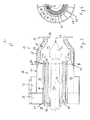
- Fig.1 shows a cut through a burner unit 10 according to a first embodiment of the present invention.
- the burner unit 10 comprises a front section 12 with a combustion chamber 14 and a rear section 16 with feed lines for feeding combustible fuel and combustion air to a mixing zone 18 of the combustion chamber 14.
- the front section 12 comprises an opening 20 for feeding flue gases from the burner unit 10 to a steel making facility such as e.g. a hot blast stove (not shown).
- the burner unit 10 is connected to the hot blast stove via a connection flange 22.
- refractory material 24 is applied against the inner surface 26 of the circumferential wall 28 to protect the latter from the heat generated in the combustion chamber 14.
- the rear section 16 which comprises the feed lines, is more easily described by referring to both Fig.1 and Fig.2 , the latter being a partial section view along line A-A of Fig.1 .
- the rear section 16 comprises an annular feed arrangement 30 alternately comprising fuel feed channels 32 and air feed channels 34.
- the fuel and air feed channels 32, 34 are arranged circumferentially, in alternating manner, preferably in regular sectors.
- the fuel feed channels 32 and air feed channels 34 respectively lead combustible fuel and combustion air from a fuel inlet 36 and an air inlet 38 to the mixing zone 18 of the combustion chamber 14.
- the combustible fuel and combustion air meet and the mixture thereof is ignited to form a first combustion, represented by flames 40.
- the annular feed arrangement 30 with its fuel and air feed channels 32, 34 forms a primary burner 42 of the burner unit 10.
- the annular feed arrangement 30 surrounds a central channel 44, which is configured so as to receive a secondary burner 46 therein.
- the annular feed arrangement 30 and central channel 44 are coaxial with a central axis 47 of the burner unit 10.
- the central channel 44 is lined with refractory material 48.
- the secondary burner 46 feeds combustible fuel and combustion air to the mixing zone 18, where a mixture thereof ignites to form a second combustion, represented by flame 50.
- the secondary burner 46 is inserted into the burner unit 10 though a socket 52 in a rear wall 54 of the burner unit 10.
- the construction of the annular feed arrangement 30 of the primary burner 42 can be more closely described by referring to Fig.2 .
- the annular feed arrangement 30 is formed by two coaxial pipes ⁇ an outer pipe 56 and an inner pipe 58 ⁇ between which an annular channel 60 is formed.
- a plurality of inner channels 61 are formed by inserting pipe-like elements 62 connected to the inner pipe 58.
- the pipe-like elements 62 form a gas tight separation wall between the inner channels 61 and the annular channel 60, thereby forming the fuel feed channels 32 and air feed channels 34.
- Auxiliary fuel feed channels 64 and auxiliary air feed channels 66 may be provided for feeding further combustible fuel and further combustion air to the mixing zone 18.
- Fig.1 shows both the auxiliary fuel feed channels 64 and the auxiliary air feed channels 66, it should be noted that it is also possible to provide the burner unit 10 with only one of these auxiliary feed channels 64, 66.
- the auxiliary fuel feed channels 64 are arranged so as to feed further combustible fuel from an annular fuel feed chamber 68 connected to a fuel inlet 70 through the circumferential wall 28 of the burner unit 10 into the mixing zone 18.
- the auxiliary air feed channels 66 are arranged so as to feed further combustion air from an annular air feed chamber 72 connected to an air inlet 74 through the circumferential wall 28 of the burner unit 10 into the mixing zone 18.
- the auxiliary fuel and air feed channels 64, 66 are low flow rate channels arranged so as to deliver high calorific gas, such as natural gas or coke oven gas or oxygen to the mixing zone 18, thereby altering the combustion conditions of the primary burner 42.
- the further fuel and/or air fed to the mixing zone 18 may be in quantities such that the mixture in the mixing zone 18 is non-stoichiometric, thereby only achieving a partial combustion with the primary burner 42. Further combustion of the flue gases from the first combustion may then be achieved with the aid of the secondary burner 46.
- Figs 3 and 4 show a burner unit 10 according to a second embodiment of the invention, wherein Fig.4 is a partial section view along line B-B of Fig.3 .
- This burner unit is very similar to the one shown in Figs 1 and 2 and will therefore not be described herein in detail. Same reference numerals refer to identical features in both embodiments.
- the burner unit of Fig. 2 and 3 differs from the first embodiment in the location of the auxiliary feed channels.
- An auxiliary air feed channel 76 is arranged between the fuel feed channels 32 and air feed channels 34 of the annular feed arrangement 30 and the refractory material 48 of the central channel 44. At one end, the auxiliary air feed channel 76 is connected to an air inlet 78 arranged in the rear wall 54 of the burner unit 10; at the opposite end, the auxiliary air feed channel 76 comprises a port 80 opening into the mixing zone 18 of the burner unit 10.
- Fig.2 shows an auxiliary air feed channel 76 only, it should be noted that it is also possible to provide the burner unit 10 with an auxiliary fuel feed channel in a similar manner.
- combustible fuel and combustion air are generally fed through the fuel feed channels 32 and air feed channels 34, so as to form a combustible mixture in the mixing zone 18.
- the flue gases from the combustion of this combustible mixture by the primary burner 42 is then fed through the opening 20 into the hot blast stove.
- the auxiliary fuel and air feed channels 64, 66 allow the introduction of additional combustible fuel and combustion air into the mixing zone 18, thereby creating a combustible mixture potentially comprising two distinctive types of combustible fuel and two distinctive types of combustion air.
- the flue gas composition can therefore be altered without having to resort to a potentially dangerous mixture upstream of the burner unit 10.
- the secondary burner not only allows burning any excess component in the flue gases from the primary burner, it also allows heating up the burner unit and any downstream equipment before the primary burner is switched on.
- the expressions "high flow rate” and “low flow rate” of the fuel and air feed channels and auxiliary fuel and air feed channels are relative to each other.
- the flow rate or section size of the feed channels will strongly depend on the combustion media used.
- Table 1 Operation mode Combustion air Combustible fuel Further combustion air Further combustible fuel Secondary burner Typical hot blast stove operation Air Blast furnace gas --- Coke oven gas --- Typical hot blast stove operation Air Blast furnace gas --- --- Post combustion burner 1 Hot blast stove heating-up operation --- --- --- Heating up burner 2 Hot blast stove temperature maintenance operation Air --- --- Natural gas --- Hot blast stove temperature maintenance operation Air --- --- Heat maintenance burner 3 Hot blast stove N2 free operation --- Blast furnace gas Oxygen --- --- Hot blast stove N2 free operation Flue gas Blast furnace gas Oxygen Natural gas Post combustion burner 4 1 post combustion burner using coke oven gas and flue gas from primary burner 2 heating up burner using coke oven gas and air 3 heat maintenance burner using oil and air 4 post combustion burner using blast furnace gas and flue gas from primary burner
Landscapes
- Engineering & Computer Science (AREA)
- Chemical & Material Sciences (AREA)
- Combustion & Propulsion (AREA)
- Mechanical Engineering (AREA)
- General Engineering & Computer Science (AREA)
- Combustion Of Fluid Fuel (AREA)
- Gas Burners (AREA)
- Pre-Mixing And Non-Premixing Gas Burner (AREA)
- Air Supply (AREA)
Abstract
Description
- The present invention relates to a burner unit for steel making facilities. More particularly, the present invention relates to an external burner unit of a regenerative or recuperative heat generator. The regenerative heat generator may e.g. be a hot blast stove of a blast furnace.
- The preheating of air for blast furnaces is conventionally carried out in adjacent regenerative heat generators known as hot blast stoves. Such stoves generally comprise a combustion chamber and a heat-retention shaft. In case of an internal combustion chamber stove, the combustion chamber and the heat-retention shaft are separated from one another by a wall constructed from refractory bricks. A burner unit is generally located in a bottom section of the combustion chamber. Combustion air and combustible fuel, generally combustible gases, are supplied to the burner unit and a mixture of the combustion air and fuel is burned in the combustion chamber of the stove. The flue gases emanating from the combustion rise upwards in the combustion chamber, are diverted via a dome and then pass through the heat-retention shaft filled with checker bricks. Heat from the flue gases is absorbed by the checker bricks. The flue gasses which have now cooled down escape the stove via an exhaust gas chamber and at least one discharge port.
- Once the checker bricks have been heated to a sufficient temperature, the supply of combustion air and fuel is discontinued and air is blown through the stove in the opposite direction. The air is heated as it passes through the heat-retention shaft containing the hot checker bricks, diverted via a dome into the combustion chamber, where it leaves the stove via a hot blast outlet in the shell of the stove to be fed to the blast furnace.
- Generally, the burner unit comprises a ceramic burner arranged within the stove, i.e. in the bottom section of its combustion chamber. It is also possible to provide external burner units, which are installed outside the shell of the stove. One or more such external burner units may be used instead of an internal ceramic burner. Alternatively, such external burner units may be used as additional heaters if used in conjunction with an internal ceramic burner.
- One advantage of such external burner units is that they are easily accessible, i.e. for maintenance or regulation purposes. Indeed, it may be advantageous to regulate the burner unit in order to achieve different temperatures or different flue gas compositions. This is of particular interest if the stove is used for experimental purposes.
- Consequently, the object of the present invention is to provide an improved burner unit for steel making facilities, in particular in connection with regenerative or recuperative heat generators. This object is achieved by a burner unit as claimed in
claim 1. - In order to achieve this object, the present invention proposes a burner unit for steel making facilities, in particular for use in connection with a regenerative or recuperative heat generator, wherein the burner unit comprises a mixing zone, a plurality of fuel feed channels for feeding combustible fuel to the mixing zone; and a plurality of air feed channels for feeding combustion air to the mixing zone. According to an important aspect of the invention, the burner unit comprises a primary burner with an annular feed arrangement comprising circumferentially alternating fuel feed channels and air feed channels; a central channel through the annular feed arrangement and a secondary burner arranged in the central channel of the burner unit, the central channel being coaxial with the annular feed arrangement.
- The primary burner may be considered as main burner, dimensioned to generally work like a conventional burner. The secondary burner may be considered as auxiliary burner for carrying out additional tasks, such as e.g. heating up the burner unit before the primary burner is switched on or aiding the combustion of the primary burner. Indeed, the secondary burner can be used as post combustion burner for using up any excess combustible fuel or combustion air from the primary burner, thereby altering the composition of the flue gasses exiting the burner unit. Whereas, in conventional burner units, only one type of combustible fuel and one type of combustion air can be used at any one time, regulation of the flue gases composition may be difficult. A mixing of different types of combustible fuel or combustion air may be carried out before feeding it to the burner unit. This is however generally cumbersome and sometimes dangerous. The present invention allows, through the use of the secondary burner, to mix different types of combustible fuel or combustion air within the burner unit; i.e. two different types of combustible fuel or combustion air may be fed to the mixing zone, thereby altering the burning conditions and the flue gas temperature and/or composition. The burner unit according to the present invention is therefore much more flexible, where operation modes are concerned, than conventional burner units.
- The burner unit may also be used to directly supply fumes of a particular composition to the steel making facility to which it is connected.
- It should be noted that the air feed channels may also be referred to as oxygen feed channels. Indeed, instead of combustion air, oxygen O2 may be fed through the air feed channels to the mixing zone.
- The fuel feed channels and the air feed channels are preferably high flow rate channels. The combustible fuel fed through the fuel feed channels may be blast furnace gas and/or the combustion air fed through the air feed channels may be air or low calorific gas.
- Advantageously, the burner unit further comprises auxiliary fuel feed channels for feeding combustible fuel to the mixing zone. Similarly, the burner unit may also further comprise auxiliary air feed channels for feeding combustion air to the mixing zone. Both the auxiliary fuel feed channels and the auxiliary air feed channels are preferably low flow rate channels. The combustible fuel fed through the auxiliary fuel feed channels may be high calorific gas, such as natural gas or coke oven gas and/or the combustion air fed through the auxiliary air feed channels may be oxygen.
- The auxiliary fuel or air feed channels allow feeding additional combustible fuel or combustion air to the mixing zone, thereby altering the combustion conditions of the primary burner.
- The additional combustible fuel or combustion air may be of the same type than that fed through the main fuel and air feed channels, thereby adjusting the burning combustion conditions of the primary burner. Preferably however, the additional combustible fuel or combustion air is of a different type than that fed through the main fuel and air feed channels, thereby also altering the composition of the flue gasses. The additional combustible fuel or combustion air may also provide the primary burner with a non-stoichiometric mixture, whereby the primary burner only achieves a partial combustion of the mixture. The secondary burner may then be used to complete the combustion of the mixture.
- The auxiliary fuel and air feed channels further contribute to the flexibility of the burner unit.
- The secondary burner preferably comprises air and fuel feed lines, thereby allowing the secondary burner to be used independently from the primary burner. It should be noted however that it is not excluded to provide the secondary burner with only one of the air and fuel feed lines. Indeed, the secondary burner may be used as post combustion burner, receiving air or fuel from the flue gasses from the primary burner.
- The secondary burner may be of any appropriate type, depending on the fuel to be used. Such fuel may be chosen from the non-exhaustive list comprising oil, coke oven gas, blast furnace gas or natural gas.
- The annular feed arrangement is preferably formed by an annular channel comprising a plurality of inner channels therein, wherein the annular channel is connected for conveying one of the combustible fuel or the combustion air and the inner channels are used for conveying the other one of the combustible fuel or the combustion air. By providing inner channels arranged in the annular channel, a gastight separation can be formed between the fuel feed channels and the air feed channels, thereby avoiding any leaks from one channel to the other within the annular feed arrangement.
- The air feed channels and fuel feed channels are preferably parallel to the central axis if the burner unit. Other configurations should however not be excluded. The air and fuel feed channels may e.g. be twisted around the central axis, which may provide a swirling of the combustible fuel and the combustion air when entering the mixing zone. Although generally not desired, in some instances such a swirl may be advantageous. It should be noted that other means for achieving a swirl may also be used.
- According to one embodiment of the invention, the auxiliary fuel feed channels and/or the auxiliary air feed channels pass through a circumferential wall of the burner unit. Annular feed chambers may be arranged around an exterior wall of the burner unit, the annular feed chambers being arranged for feeding combustible fuel or combustion air to the auxiliary fuel feed channels and the auxiliary air feed channels.
- According to another embodiment of the invention, the auxiliary fuel feed channels and/or the auxiliary air feed channels pass through a rear wall of the burner unit, the auxiliary fuel feed channels and/or the auxiliary air feed channels being arranged parallel to the axis of the burner unit. The auxiliary fuel feed channels and/or the auxiliary air feed channels may be arranged between the annular feed arrangement of the primary burner and the secondary burner. Alternatively, the auxiliary fuel feed channels and/or the auxiliary air feed channels may be arranged within the annular feed arrangement of the primary burner.
- It should be noted that, although the present application mainly describes a burner unit in connection with a hot blast stove, the burner unit may also be used in connection with other steel making facilities, such as e.g. pulverised coal injection (PCI) installations or direct recuperative heat exchangers.
- The present invention will be more apparent from the following description of a not limiting embodiment with reference to the attached drawings. In these drawings, wherein identical reference numerals are used to indicate identical or similar elements,
- Fig.1:
- is a cut through a burner unit according to a first embodiment of the present invention;
- Fig.2:
- is a partial section view across the burner unit along line A-A of
Fig.1 ; - Fig.3:
- is a cut through a burner unit according to a second embodiment of the present invention; and
- Fig.4:
- is a partial section view across the burner unit along line B-B of
Fig.3 . -
Fig.1 shows a cut through a burner unit 10 according to a first embodiment of the present invention. The burner unit 10 comprises afront section 12 with a combustion chamber 14 and arear section 16 with feed lines for feeding combustible fuel and combustion air to a mixing zone 18 of the combustion chamber 14. Thefront section 12 comprises an opening 20 for feeding flue gases from the burner unit 10 to a steel making facility such as e.g. a hot blast stove (not shown). The burner unit 10 is connected to the hot blast stove via aconnection flange 22. In thefront section 12,refractory material 24 is applied against the inner surface 26 of thecircumferential wall 28 to protect the latter from the heat generated in the combustion chamber 14. - The
rear section 16, which comprises the feed lines, is more easily described by referring to bothFig.1 and Fig.2 , the latter being a partial section view along line A-A ofFig.1 . Therear section 16 comprises anannular feed arrangement 30 alternately comprisingfuel feed channels 32 andair feed channels 34. The fuel andair feed channels fuel feed channels 32 andair feed channels 34 respectively lead combustible fuel and combustion air from afuel inlet 36 and anair inlet 38 to the mixing zone 18 of the combustion chamber 14. - In the mixing zone 18 the combustible fuel and combustion air meet and the mixture thereof is ignited to form a first combustion, represented by
flames 40. Theannular feed arrangement 30 with its fuel andair feed channels primary burner 42 of the burner unit 10. - The
annular feed arrangement 30 surrounds acentral channel 44, which is configured so as to receive asecondary burner 46 therein. Theannular feed arrangement 30 andcentral channel 44 are coaxial with acentral axis 47 of the burner unit 10. Thecentral channel 44 is lined withrefractory material 48. Thesecondary burner 46 feeds combustible fuel and combustion air to the mixing zone 18, where a mixture thereof ignites to form a second combustion, represented byflame 50. Thesecondary burner 46 is inserted into the burner unit 10 though asocket 52 in arear wall 54 of the burner unit 10. - The construction of the
annular feed arrangement 30 of theprimary burner 42 can be more closely described by referring toFig.2 . Theannular feed arrangement 30 is formed by two coaxial pipes ―anouter pipe 56 and aninner pipe 58 ―between which an annular channel 60 is formed. Within the annular channel 60, a plurality of inner channels 61 are formed by inserting pipe-like elements 62 connected to theinner pipe 58. The pipe-like elements 62 form a gas tight separation wall between the inner channels 61 and the annular channel 60, thereby forming thefuel feed channels 32 andair feed channels 34. - Auxiliary fuel feed channels 64 and auxiliary air feed channels 66 may be provided for feeding further combustible fuel and further combustion air to the mixing zone 18. Although,
Fig.1 shows both the auxiliary fuel feed channels 64 and the auxiliary air feed channels 66, it should be noted that it is also possible to provide the burner unit 10 with only one of these auxiliary feed channels 64, 66. - The auxiliary fuel feed channels 64 are arranged so as to feed further combustible fuel from an annular
fuel feed chamber 68 connected to afuel inlet 70 through thecircumferential wall 28 of the burner unit 10 into the mixing zone 18. Similarly, the auxiliary air feed channels 66 are arranged so as to feed further combustion air from an annularair feed chamber 72 connected to anair inlet 74 through thecircumferential wall 28 of the burner unit 10 into the mixing zone 18. - The auxiliary fuel and air feed channels 64, 66 are low flow rate channels arranged so as to deliver high calorific gas, such as natural gas or coke oven gas or oxygen to the mixing zone 18, thereby altering the combustion conditions of the
primary burner 42. The further fuel and/or air fed to the mixing zone 18 may be in quantities such that the mixture in the mixing zone 18 is non-stoichiometric, thereby only achieving a partial combustion with theprimary burner 42. Further combustion of the flue gases from the first combustion may then be achieved with the aid of thesecondary burner 46. -
Figs 3 and 4 show a burner unit 10 according to a second embodiment of the invention, whereinFig.4 is a partial section view along line B-B ofFig.3 . This burner unit is very similar to the one shown inFigs 1 and 2 and will therefore not be described herein in detail. Same reference numerals refer to identical features in both embodiments. The burner unit ofFig. 2 and3 differs from the first embodiment in the location of the auxiliary feed channels. - An auxiliary air feed channel 76 is arranged between the
fuel feed channels 32 andair feed channels 34 of theannular feed arrangement 30 and therefractory material 48 of thecentral channel 44. At one end, the auxiliary air feed channel 76 is connected to an air inlet 78 arranged in therear wall 54 of the burner unit 10; at the opposite end, the auxiliary air feed channel 76 comprises a port 80 opening into the mixing zone 18 of the burner unit 10. - Although
Fig.2 shows an auxiliary air feed channel 76 only, it should be noted that it is also possible to provide the burner unit 10 with an auxiliary fuel feed channel in a similar manner. - During typical operation of the burner unit 10, combustible fuel and combustion air are generally fed through the
fuel feed channels 32 andair feed channels 34, so as to form a combustible mixture in the mixing zone 18. The flue gases from the combustion of this combustible mixture by theprimary burner 42 is then fed through the opening 20 into the hot blast stove. - The auxiliary fuel and air feed channels 64, 66 allow the introduction of additional combustible fuel and combustion air into the mixing zone 18, thereby creating a combustible mixture potentially comprising two distinctive types of combustible fuel and two distinctive types of combustion air. The flue gas composition can therefore be altered without having to resort to a potentially dangerous mixture upstream of the burner unit 10.
- The secondary burner not only allows burning any excess component in the flue gases from the primary burner, it also allows heating up the burner unit and any downstream equipment before the primary burner is switched on.
- To adjust the temperature, flow rated or composition of the flue gases fed to the hot blast stove, numerous combinations of burners and combustion media are available due to the innovative design of the present burner unit.
- It should be noted that, in the context of the present invention, the expressions "high flow rate" and "low flow rate" of the fuel and air feed channels and auxiliary fuel and air feed channels are relative to each other. The flow rate or section size of the feed channels will strongly depend on the combustion media used. Purely for the purpose of providing an example, the high flow rate, fuel and
air feed channels - A non-exhaustive list of examples for operation modes of the burner unit according to the present invention is shown in Table 1.
Table 1 Operation mode Combustion air Combustible fuel Further combustion air Further combustible fuel Secondary burner Typical hot blast stove operation Air Blast furnace gas --- Coke oven gas --- Typical hot blast stove operation Air Blast furnace gas --- --- Post combustion burner1 Hot blast stove heating-up operation --- --- --- --- Heating up burner2 Hot blast stove temperature maintenance operation Air --- --- Natural gas --- Hot blast stove temperature maintenance operation Air --- --- --- Heat maintenance burner3 Hot blast stove N2 free operation --- Blast furnace gas Oxygen --- --- Hot blast stove N2 free operation Flue gas Blast furnace gas Oxygen Natural gas Post combustion burner4 1 post combustion burner using coke oven gas and flue gas from primary burner 2 heating up burner using coke oven gas and air 3 heat maintenance burner using oil and air 4 post combustion burner using blast furnace gas and flue gas from primary burner -
- 10
- burner unit
- 12
- front section
- 14
- combustion chamber
- 16
- rear section
- 18
- mixing zone
- 20
- opening
- 22
- connection flange
- 24
- refractory material
- 26
- inner surface
- 28
- circumferential wall
- 30
- annular feed arrangement
- 32
- fuel feed channels
- 34
- air feed channels
- 36
- fuel inlet
- 38
- air inlet
- 40
- flames
- 42
- primary burner
- 44
- central channel
- 46
- secondary burner
- 50
- flame
- 52
- socket
- 54
- rear wall
- 56
- outer pipe
- 58
- inner pipe
- 60
- annular channel
- 61
- inner channels
- 62
- pipe-like elements
- 64
- auxiliary fuel feed channels
- 66
- auxiliary air feed channels
- 68
- annular fuel feed chamber
- 70
- fuel inlet
- 72
- annular air feed chamber
- 74
- air inlet
- 76
- auxiliary air feed channel
- 78
- air inlet
- 80
- port
Claims (14)
- Burner unit for steel making facilities, in particular for use in connection with a regenerative or recuperative heat generator, wherein the burner unit comprises:a mixing zone;a plurality of fuel feed channels for feeding combustible fuel to said mixing zone; anda plurality of air feed channels for feeding combustion air to said mixing zonecharacterised bya primary burner with an annular feed arrangement comprising circumferentially alternating fuel feed channels and air feed channels;a central channel through said annular feed arrangement, said central channel being coaxial with said annular feed arrangement; anda secondary burner arranged in said central channel of said burner unit.
- Burner unit according to claim 1, wherein said fuel feed channels and said air feed channels are high flow rate channels.
- Burner unit according to claim 2, wherein said burner unit further comprises auxiliary fuel feed channels for feeding combustible fuel to said mixing zone, said auxiliary fuel feed channels being low flow rate channels.
- Burner unit according to claim 2 or 3, wherein said burner unit further comprises
auxiliary air feed channels for feeding combustion air to said mixing zone, said auxiliary air feed channels being low flow rate channels. - Burner unit according to claim 1 to 4, wherein
said combustible fuel is blast furnace gas, and/or
said combustion air is air or low calorific gas. - Burner unit according to claim 4 or 5, wherein
said combustible fuel fed through said auxiliary fuel feed channels is high calorific gas, such as natural gas or coke oven gas, and/or
said combustion air fed through said auxiliary air feed channels is oxygen. - Burner unit according to any one of the preceding claims, wherein said secondary burner comprises air and fuel feed lines.
- Burner unit according to any one of the preceding claims, wherein said annular feed arrangement is formed by an annular channel comprising a plurality of inner channels therein, said annular channel being connected for conveying one of said combustible fuel or said combustion air, said inner channels being used for conveying the other one of said combustible fuel or said combustion air.
- Burner unit according to any one of the preceding claims, wherein said air feed channels and fuel feed channels are parallel to the central axis of said burner unit.
- Burner unit according to any one of claims 3 to 9, wherein said auxiliary fuel feed channels and/or said auxiliary air feed channels pass through a circumferential wall of said burner unit.
- Burner unit according to claim 10, wherein annular feed chambers are arranged around an exterior wall of said burner unit, said annular feed chambers being arranged for feeding fuel or air to said auxiliary fuel feed channels and said auxiliary air feed channels.
- Burner unit according to any one of claims 3 to 9, wherein said auxiliary fuel feed channels and/or said auxiliary air feed channels pass through a rear wall of said burner unit, said auxiliary fuel feed channels and/or said auxiliary air feed channels being arranged parallel to the axis of said burner unit.
- Burner unit according to claim 12, wherein said auxiliary fuel feed channels and/or said auxiliary air feed channels are arranged between said annular feed arrangement of said primary burner and said secondary burner.
- Burner unit according to claim 12, wherein said auxiliary fuel feed channels and/or said auxiliary air feed channels are arranged within said annular feed arrangement of said primary burner.
Priority Applications (12)
| Application Number | Priority Date | Filing Date | Title |
|---|---|---|---|
| EP09178385A EP2333412A1 (en) | 2009-12-08 | 2009-12-08 | Burner unit for steel making facilities |
| DE9178385T DE09178385T1 (en) | 2009-12-08 | 2009-12-08 | Burner unit for steelworks |
| CA2782763A CA2782763A1 (en) | 2009-12-08 | 2010-12-08 | Burner unit for steel making facilities |
| CN201080055601.2A CN102713436B (en) | 2009-12-08 | 2010-12-08 | Combustion devices for steelmaking plants |
| EP10787770.6A EP2510283B1 (en) | 2009-12-08 | 2010-12-08 | Burner unit for steel making facilities |
| AU2010329886A AU2010329886B2 (en) | 2009-12-08 | 2010-12-08 | Burner unit for steel making facilities |
| IN4997DEN2012 IN2012DN04997A (en) | 2009-12-08 | 2010-12-08 | |
| PCT/EP2010/069177 WO2011070070A2 (en) | 2009-12-08 | 2010-12-08 | Burner unit for steel making facilities |
| JP2012542538A JP5636435B2 (en) | 2009-12-08 | 2010-12-08 | Burner equipment for steelmaking facilities |
| KR1020127017672A KR101732396B1 (en) | 2009-12-08 | 2010-12-08 | Burner uint for steel making facilities |
| RU2012128355/06A RU2533269C2 (en) | 2009-12-08 | 2010-12-08 | Burner module for steel-casting units |
| BR112012013643-7A BR112012013643B1 (en) | 2009-12-08 | 2010-12-08 | BURNING UNIT FOR STEEL INSTALLATIONS |
Applications Claiming Priority (1)
| Application Number | Priority Date | Filing Date | Title |
|---|---|---|---|
| EP09178385A EP2333412A1 (en) | 2009-12-08 | 2009-12-08 | Burner unit for steel making facilities |
Publications (1)
| Publication Number | Publication Date |
|---|---|
| EP2333412A1 true EP2333412A1 (en) | 2011-06-15 |
Family
ID=41563196
Family Applications (2)
| Application Number | Title | Priority Date | Filing Date |
|---|---|---|---|
| EP09178385A Withdrawn EP2333412A1 (en) | 2009-12-08 | 2009-12-08 | Burner unit for steel making facilities |
| EP10787770.6A Active EP2510283B1 (en) | 2009-12-08 | 2010-12-08 | Burner unit for steel making facilities |
Family Applications After (1)
| Application Number | Title | Priority Date | Filing Date |
|---|---|---|---|
| EP10787770.6A Active EP2510283B1 (en) | 2009-12-08 | 2010-12-08 | Burner unit for steel making facilities |
Country Status (11)
| Country | Link |
|---|---|
| EP (2) | EP2333412A1 (en) |
| JP (1) | JP5636435B2 (en) |
| KR (1) | KR101732396B1 (en) |
| CN (1) | CN102713436B (en) |
| AU (1) | AU2010329886B2 (en) |
| BR (1) | BR112012013643B1 (en) |
| CA (1) | CA2782763A1 (en) |
| DE (1) | DE09178385T1 (en) |
| IN (1) | IN2012DN04997A (en) |
| RU (1) | RU2533269C2 (en) |
| WO (1) | WO2011070070A2 (en) |
Cited By (2)
| Publication number | Priority date | Publication date | Assignee | Title |
|---|---|---|---|---|
| CN102408919A (en) * | 2011-10-11 | 2012-04-11 | 北京航天动力研究所 | Combustion nozzle combination device of multi-channel coal water slurry gasification furnace |
| WO2018148478A1 (en) * | 2017-02-13 | 2018-08-16 | Bloom Engineering Company Inc. | Dual mode regenerative burner system and a method of heating a furnace using a dual mode regenerative burner system |
Families Citing this family (5)
| Publication number | Priority date | Publication date | Assignee | Title |
|---|---|---|---|---|
| CN103044036B (en) * | 2013-01-07 | 2014-09-24 | 中钢集团洛阳耐火材料研究院有限公司 | Sintering method of self-combination silicon-carbide refractories |
| JP6073270B2 (en) * | 2014-09-18 | 2017-02-01 | ボルカノ株式会社 | Combustion device, boiler, and combustion method |
| JP6054349B2 (en) * | 2014-09-03 | 2016-12-27 | ボルカノ株式会社 | Combustion device, boiler, and combustion method |
| US10520221B2 (en) | 2015-04-06 | 2019-12-31 | Carrier Corporation | Refractory for heating system |
| WO2018195789A1 (en) * | 2017-04-26 | 2018-11-01 | Linde Aktiengesellschaft | Method and burner for heating a furnace for metal processing |
Citations (5)
| Publication number | Priority date | Publication date | Assignee | Title |
|---|---|---|---|---|
| US2942655A (en) * | 1955-04-27 | 1960-06-28 | Fisher Scientific Co | Gas burner |
| GB957110A (en) * | 1961-11-22 | 1964-05-06 | British Oxygen Co Ltd | Process and jet for the treatment of metal |
| US3834864A (en) * | 1972-03-29 | 1974-09-10 | Koppers Gmbh Heinrich | Regenerator construction |
| EP1205710A1 (en) * | 1999-08-17 | 2002-05-15 | Nippon Furnace Kogyo Kabushiki Kaisha | Combustion method and burner |
| WO2007045807A1 (en) * | 2005-10-21 | 2007-04-26 | Lafarge | Burner for a clinker furnace |
Family Cites Families (8)
| Publication number | Priority date | Publication date | Assignee | Title |
|---|---|---|---|---|
| SU964348A1 (en) * | 1981-01-05 | 1982-10-07 | Всесоюзный Научно-Исследовательский И Проектный Институт Вторичной Цветной Металлургии | Burner |
| US4403947A (en) * | 1981-08-12 | 1983-09-13 | Eclipse, Inc. | Gas mixing burner |
| SU1467322A1 (en) * | 1987-03-23 | 1989-03-23 | Предприятие П/Я Р-6603 | Burner device |
| US5454712A (en) * | 1993-09-15 | 1995-10-03 | The Boc Group, Inc. | Air-oxy-fuel burner method and apparatus |
| US5714113A (en) * | 1994-08-29 | 1998-02-03 | American Combustion, Inc. | Apparatus for electric steelmaking |
| JP4068041B2 (en) * | 2002-10-22 | 2008-03-26 | 日本碍子株式会社 | Low NOx burner |
| JP2005226850A (en) * | 2004-02-10 | 2005-08-25 | Ebara Corp | Combustion device |
| US7810333B2 (en) * | 2006-10-02 | 2010-10-12 | General Electric Company | Method and apparatus for operating a turbine engine |
-
2009
- 2009-12-08 EP EP09178385A patent/EP2333412A1/en not_active Withdrawn
- 2009-12-08 DE DE9178385T patent/DE09178385T1/en active Pending
-
2010
- 2010-12-08 KR KR1020127017672A patent/KR101732396B1/en active Active
- 2010-12-08 BR BR112012013643-7A patent/BR112012013643B1/en active IP Right Grant
- 2010-12-08 WO PCT/EP2010/069177 patent/WO2011070070A2/en not_active Ceased
- 2010-12-08 RU RU2012128355/06A patent/RU2533269C2/en active
- 2010-12-08 AU AU2010329886A patent/AU2010329886B2/en not_active Expired - Fee Related
- 2010-12-08 IN IN4997DEN2012 patent/IN2012DN04997A/en unknown
- 2010-12-08 CN CN201080055601.2A patent/CN102713436B/en active Active
- 2010-12-08 EP EP10787770.6A patent/EP2510283B1/en active Active
- 2010-12-08 CA CA2782763A patent/CA2782763A1/en not_active Abandoned
- 2010-12-08 JP JP2012542538A patent/JP5636435B2/en active Active
Patent Citations (5)
| Publication number | Priority date | Publication date | Assignee | Title |
|---|---|---|---|---|
| US2942655A (en) * | 1955-04-27 | 1960-06-28 | Fisher Scientific Co | Gas burner |
| GB957110A (en) * | 1961-11-22 | 1964-05-06 | British Oxygen Co Ltd | Process and jet for the treatment of metal |
| US3834864A (en) * | 1972-03-29 | 1974-09-10 | Koppers Gmbh Heinrich | Regenerator construction |
| EP1205710A1 (en) * | 1999-08-17 | 2002-05-15 | Nippon Furnace Kogyo Kabushiki Kaisha | Combustion method and burner |
| WO2007045807A1 (en) * | 2005-10-21 | 2007-04-26 | Lafarge | Burner for a clinker furnace |
Cited By (3)
| Publication number | Priority date | Publication date | Assignee | Title |
|---|---|---|---|---|
| CN102408919A (en) * | 2011-10-11 | 2012-04-11 | 北京航天动力研究所 | Combustion nozzle combination device of multi-channel coal water slurry gasification furnace |
| WO2018148478A1 (en) * | 2017-02-13 | 2018-08-16 | Bloom Engineering Company Inc. | Dual mode regenerative burner system and a method of heating a furnace using a dual mode regenerative burner system |
| US10895379B2 (en) | 2017-02-13 | 2021-01-19 | Bloom Engineering Company, Inc. | Dual mode regenerative burner system and a method of heating a furnace using a dual mode regenerative burner system |
Also Published As
| Publication number | Publication date |
|---|---|
| DE09178385T1 (en) | 2011-12-01 |
| AU2010329886A1 (en) | 2012-06-21 |
| BR112012013643B1 (en) | 2021-08-17 |
| EP2510283B1 (en) | 2013-07-03 |
| RU2533269C2 (en) | 2014-11-20 |
| BR112012013643A2 (en) | 2020-08-25 |
| IN2012DN04997A (en) | 2015-10-02 |
| EP2510283A2 (en) | 2012-10-17 |
| JP5636435B2 (en) | 2014-12-03 |
| AU2010329886B2 (en) | 2014-09-18 |
| KR101732396B1 (en) | 2017-05-24 |
| WO2011070070A3 (en) | 2011-08-11 |
| CN102713436B (en) | 2014-11-12 |
| KR20120101531A (en) | 2012-09-13 |
| CN102713436A (en) | 2012-10-03 |
| JP2013513084A (en) | 2013-04-18 |
| RU2012128355A (en) | 2014-01-20 |
| WO2011070070A2 (en) | 2011-06-16 |
| CA2782763A1 (en) | 2011-06-16 |
Similar Documents
| Publication | Publication Date | Title |
|---|---|---|
| EP2510283B1 (en) | Burner unit for steel making facilities | |
| US20090120338A1 (en) | Process and Apparatus for Low-NOx Combustion | |
| CN101446413A (en) | Combined type multi-injector burner | |
| US9574770B2 (en) | Start-up torch | |
| US20250327568A1 (en) | Low nox, high efficiency, high temperature, staged recirculating burner and radiant tube combustion system | |
| EP3173696A1 (en) | Top combustion stove | |
| US4156590A (en) | Combustion in a melting furnace | |
| CN115516265B (en) | Cement manufacturing equipment and method for producing cement clinker | |
| WO2018201259A1 (en) | Plasma heating blast air | |
| CN104541102B (en) | Method for operating a multi-gas burner and multi-gas burner | |
| WO2009047260A3 (en) | Burner for an industrial furnace | |
| RU2766115C2 (en) | Burner for combusting gaseous fuel in a shaft furnace, primarily for heat treatment of minerals in the granular form | |
| KR100761211B1 (en) | A partial combustion burner for preheating oxygen | |
| CA2490637C (en) | Method and burner for rotary kilns | |
| CN216384169U (en) | Pilot burner and hot-blast stove suitable for burning gas containing dust and tar | |
| CN101400810B (en) | Apparatus and method for gas heating in connection with sintering | |
| CN224033805U (en) | Process burner and reaction furnace | |
| RU32862U1 (en) | Gas-burner | |
| CN119665235A (en) | Process burner, reaction furnace and method for treating gaseous fuel with process burner | |
| JPS595541B2 (en) | Coal combustion method in vertical firing equipment | |
| TW201508225A (en) | Method for operating a multi-gas burner and a multi-gas burner |
Legal Events
| Date | Code | Title | Description |
|---|---|---|---|
| PUAI | Public reference made under article 153(3) epc to a published international application that has entered the european phase |
Free format text: ORIGINAL CODE: 0009012 |
|
| AK | Designated contracting states |
Kind code of ref document: A1 Designated state(s): AT BE BG CH CY CZ DE DK EE ES FI FR GB GR HR HU IE IS IT LI LT LU LV MC MK MT NL NO PL PT RO SE SI SK SM TR |
|
| AX | Request for extension of the european patent |
Extension state: AL BA RS |
|
| REG | Reference to a national code |
Ref country code: DE Ref legal event code: R210 Effective date: 20111201 |
|
| 17P | Request for examination filed |
Effective date: 20111104 |
|
| 17Q | First examination report despatched |
Effective date: 20111229 |
|
| STAA | Information on the status of an ep patent application or granted ep patent |
Free format text: STATUS: THE APPLICATION IS DEEMED TO BE WITHDRAWN |
|
| 18D | Application deemed to be withdrawn |
Effective date: 20120710 |