EP2333315A2 - System and method for arranging wind turbine blades - Google Patents
System and method for arranging wind turbine blades Download PDFInfo
- Publication number
- EP2333315A2 EP2333315A2 EP10191953A EP10191953A EP2333315A2 EP 2333315 A2 EP2333315 A2 EP 2333315A2 EP 10191953 A EP10191953 A EP 10191953A EP 10191953 A EP10191953 A EP 10191953A EP 2333315 A2 EP2333315 A2 EP 2333315A2
- Authority
- EP
- European Patent Office
- Prior art keywords
- wind turbine
- root
- turbine blades
- cradle
- blade
- Prior art date
- Legal status (The legal status is an assumption and is not a legal conclusion. Google has not performed a legal analysis and makes no representation as to the accuracy of the status listed.)
- Withdrawn
Links
Images



Classifications
-
- B—PERFORMING OPERATIONS; TRANSPORTING
- B60—VEHICLES IN GENERAL
- B60P—VEHICLES ADAPTED FOR LOAD TRANSPORTATION OR TO TRANSPORT, TO CARRY, OR TO COMPRISE SPECIAL LOADS OR OBJECTS
- B60P3/00—Vehicles adapted to transport, to carry or to comprise special loads or objects
- B60P3/40—Vehicles adapted to transport, to carry or to comprise special loads or objects for carrying long loads, e.g. with separate wheeled load supporting elements
-
- F—MECHANICAL ENGINEERING; LIGHTING; HEATING; WEAPONS; BLASTING
- F05—INDEXING SCHEMES RELATING TO ENGINES OR PUMPS IN VARIOUS SUBCLASSES OF CLASSES F01-F04
- F05B—INDEXING SCHEME RELATING TO WIND, SPRING, WEIGHT, INERTIA OR LIKE MOTORS, TO MACHINES OR ENGINES FOR LIQUIDS COVERED BY SUBCLASSES F03B, F03D AND F03G
- F05B2260/00—Function
- F05B2260/02—Transport, e.g. specific adaptations or devices for conveyance
-
- Y—GENERAL TAGGING OF NEW TECHNOLOGICAL DEVELOPMENTS; GENERAL TAGGING OF CROSS-SECTIONAL TECHNOLOGIES SPANNING OVER SEVERAL SECTIONS OF THE IPC; TECHNICAL SUBJECTS COVERED BY FORMER USPC CROSS-REFERENCE ART COLLECTIONS [XRACs] AND DIGESTS
- Y10—TECHNICAL SUBJECTS COVERED BY FORMER USPC
- Y10T—TECHNICAL SUBJECTS COVERED BY FORMER US CLASSIFICATION
- Y10T29/00—Metal working
- Y10T29/49—Method of mechanical manufacture
- Y10T29/49229—Prime mover or fluid pump making
-
- Y—GENERAL TAGGING OF NEW TECHNOLOGICAL DEVELOPMENTS; GENERAL TAGGING OF CROSS-SECTIONAL TECHNOLOGIES SPANNING OVER SEVERAL SECTIONS OF THE IPC; TECHNICAL SUBJECTS COVERED BY FORMER USPC CROSS-REFERENCE ART COLLECTIONS [XRACs] AND DIGESTS
- Y10—TECHNICAL SUBJECTS COVERED BY FORMER USPC
- Y10T—TECHNICAL SUBJECTS COVERED BY FORMER US CLASSIFICATION
- Y10T29/00—Metal working
- Y10T29/53—Means to assemble or disassemble
Definitions
- the present invention generally involves wind turbine blades.
- the present invention discloses and enables systems and methods for arranging at least two wind turbine blades for storage and/or transport.
- Wind turbines are well known in the art for converting kinetic energy from the wind to mechanical or electrical energy, and wind turbine blades exist in various shapes and sizes.
- some blades include a root at one end and a tip at the opposite end.
- the blade root attaches to a rotor, and the blade extends radially outward from the blade root to the blade tip.
- the blade may have a rounded or curved leading edge (i.e., the edge facing the direction of rotation) and a tapered or pointed trailing edge (i.e., the edge facing away from the direction of rotation), producing a blade with an aerodynamic or airfoil shape.
- the blade may be curved from the blade root to the blade tip, creating a convex surface on the top of the blade (i.e., the surface of the blade facing toward the oncoming wind) and a concave surface on the back of the blade (i.e., the surface of the blade facing away from the oncoming wind).
- wind turbine blades vary, depending on the size of the wind turbine, anticipated wind speeds, and other design considerations.
- wind turbine blades may extend greater than 100 feet, have an effective width of 9 feet or greater, curve more than 6 feet from blade root to blade tip, and weigh more than 13,000 pounds.
- State and local transportation regulations include limits regarding the maximum allowed width and height of items transported on public roads.
- the maximum allowable width is typically 81 ⁇ 2 feet, and the maximum allowable height ranges between 131 ⁇ 2 and 14 feet, depending on the location.
- the maximum allowable width is typically 11 feet 5 3 ⁇ 4 inches, and the maximum allowable height is 14 feet 7 inches.
- the size, shape, and weight of wind turbine blades generally requires that wind turbine blades be transported individually so as to not exceed the allowable size limits, increasing the cost of transporting wind turbine blades.
- a system for arranging first and second wind turbine blades includes a first root cradle and a second root cradle opposed to the first root cradle and separated from the first root cradle.
- the system further includes a first tip cradle proximate to the second root cradle, wherein the first tip cradle defines a first support plane angled approximately 30 to 60 degrees with respect to a horizontal line.
- the system also includes a second tip cradle proximate to the first root cradle, wherein the second tip cradle defines a second support plane angled approximately 30 to 60 degrees with respect to the horizontal line.
- Another embodiment of the present invention is a method for arranging at least two wind turbine blades.
- the method includes transferring a first wind turbine blade to a first root cradle and rotating the first wind turbine blade so that the first wind turbine blade is angled approximately 30 to 60 degrees with respect to a horizontal line.
- the method further includes transferring a second wind turbine blade to a second root cradle and rotating the second wind turbine blade so that the second wind turbine blade is angled approximately 30 to 60 degrees with respect to the horizontal line.
- Another method for arranging at least two wind turbine blades within the scope of the present invention includes transferring a first wind turbine blade to a first root cradle and transferring a second wind turbine blade to a second root cradle. The method further includes rotating at least a portion of the first wind turbine blade about at least a portion of the second wind turbine blade.
- FIGS 1 , 2 , and 3 provide perspective views of a system 10 for arranging first and second wind turbine blades 12, 14 for transport and/or storage according to one embodiment of the present invention.
- Each wind turbine blade 12, 14 generally includes a blade root 16, 18 at one end and a blade tip 20, 22 at the opposite end.
- Each blade root 16, 18 is generally round in cross-section and includes bolts, screws, studs 24, or other structure known in the art for attaching a wind turbine blade to a rotor of a wind turbine.
- the wind turbine blades 12, 14 typically extend up to 80-120 feet, or more, and gradually curve from the blade root to the blade tip, creating a convex surface 26 on one side and a concave surface 28 on the opposite side.
- the wind turbine blades 12, 14 may have a rounded leading edge 30 (i.e., the edge facing the direction of rotation) and a tapered trailing edge 32 (i.e., the edge facing away from the direction of rotation) that combine to give the wind turbine blades 12, 14 an aerodynamic or airfoil shape.
- wind turbine blades 12, 14 shown in Figures 1 , 2 , and 3 are arranged in an inverted position to one another with the concave surfaces 28 facing one another and the leading edges 30 down.
- each blade root 16, 18 is near or proximate to the blade tip 20, 22 of the opposite wind turbine blade, and the opposing concave surfaces 28 create a space 33 between the first and second wind turbine blades 12, 14 near the middle of the wind turbine blades.
- the system 10 generally includes first and second root cradles 34, 36 and first and second tip cradles 38, 40.
- the root and tip cradles provide support and cushioning for the blade roots and blade tips, respectively.
- the first root cradle 34 and the first tip cradle 38 refer to the structures that support the first wind turbine blade 12
- the second root cradle 36 and the second tip cradle 40 refer to the structures that support the second wind turbine blade 14.
- the first and second root cradles 34, 36 are opposed to each other and are separated by a distance that is approximately equal to the length of the wind turbine blades.
- the first tip cradle 38 is located closer to or proximate to the second root cradle 36 to support and cushion the blade tip 20 of the first wind turbine blade 12, and the second tip cradle 40 is located closer to or proximate to the first root cradle 34 to support and cushion the blade tip 22 of the second wind turbine blade 14.
- a frame 42 around the first and second root cradles 34, 36 may connect to and support the second and first tip cradles 40, 38, respectively, as shown in Figures 1 and 2 .
- the tip cradles may be structurally separate from the proximate root cradles.
- the root cradles 34, 36 and tip cradles 38, 40 generally include cushions 44 or pads that form a seating surface which conforms to the exterior surface of the blade root or blade tip.
- the weight of the wind turbine blades 12, 14 against the cushions 44 holds the wind turbine blades 12, 14 in place.
- the cushions 44 or pads may be configured to completely or partially surround the blade roots 16, 18 and/or blade tips 20, 22.
- a strap 46, banding, or other suitable device may be used to hold the wind turbine blades 12, 14 in place.
- the first and second tip cradles 38, 40 define first and second support planes 48, 50, respectively, that are angled approximately 30 to 60 degrees with respect to a horizontal line 49.
- the first and second support planes 48, 50 may be angled approximately 35 to 55 degrees, 40 to 50 degrees, or 45 degrees with respect to the horizontal line 49.
- the first and second tip cradles 38, 40 and associated first and second support planes 48, 50 thus position the first and second blade tips 20, 22 diagonally with respect to the second and first root cradles 18, 16, respectively.
- the first and second support planes 48, 50 may include a first surface formed from the cushions 44 or pads in the respective tip cradle, with or without a second surface opposed to the first surface.
- the second surface if present, may include additional cushions 44 or pads, or the second surface may simply be a strap 46, banding, or other suitable devices to secure the blade tips 20, 22 in the tip cradles 38, 40.
- the system 10 further includes a clamp 56 between the first and second root cradles 34, 36 and near or proximate to the middle of the first and second wind turbine blades 12, 14.
- Padded frames 58 may surround the first and second wind turbine blades 12, 14 and connect the clamp 56 to the first and second wind turbine blades 12, 14.
- the clamp 56 may include a turnbuckle 60, winch, pulley, ram, or other equivalent device known to one of ordinary skill in the art to provide a mechanical advantage for moving at least a portion of the first and second wind turbine blades 12, 14 together.
- rotation of the turnbuckle 60 may cause the clamp 56 to retract and move at least a portion of the first and second wind turbine blades 12, 14 together.
- the retracted clamp 56 thus at least partially straightens one or both of the wind turbine blades 12, 14 to reduce the space 33 between the wind turbine blades 12, 14.
- Other suitable and equivalent means for straightening at least one of the wind turbine blades 12, 14 may include counter-weights and/or hydraulic, pneumatic, or electromechanical presses.
- FIG 2 shows the embodiment of the system 10 and wind turbine blades 12, 14 shown in Figure 1 with the clamp 56 in a retracted position.
- the middle of the first and second wind turbine blades 12, 14 are drawn closer together, thereby reducing the space 33 between the wind turbine blades 12, 14.
- Figure 3 shows the embodiment of the system 10 and wind turbine blades 12, 14 shown in Figures 1 and 2 loaded on a commercial carrier 62 for transport and/or storage.
- the orientation of the system 10 and wind turbine blades 12, 14 in Figure 3 has been reversed from that shown in Figures 1 and 2 to show the opposite side of the system 10 not visible in Figures 1 and 2 .
- the first and second tip cradles 38, 40 and the first and second root cradles 34, 36 support the first and second wind turbine blades 12, 14 at an angle approximately 30 to 60 degrees with respect to the horizontal line 49.
- the first and second wind turbine blades 12, 14 may be angled approximately 35 to 55 degrees, 40 to 50 degrees, or 45 degrees with respect to the horizontal line 49.
- the system 10 arranges the wind turbine blades 12, 14 approximately diagonally with respect to the horizontal line 49 to reduce the width and height of the system 10 and wind turbine blades 12, 14 during transportation and/or storage.
- Figure 4 shows an end view of the system 10 (in phantom) and wind turbine blades shown in Figure 2 .
- a shipping area 64 for the system 10 and the wind turbine blades 12, 14 is defined as the maximum width and height of the outer perimeter of the system 10 and wind turbine blades 12, 14.
- the shipping area 64 is shown in Figure 4 as a dashed box circumscribing the outer perimeter of the system 10 and wind turbine blades 12, 14. With the wind turbine blades 12, 14 arranged within the system 10, the shipping area has a maximum width of 81 ⁇ 2 feet and a maximum height of 131 ⁇ 2 feet. It will be appreciated that the shipping area 64 defined by the system 10 and wind turbine blades 12, 14 may fit within or extend beyond the width and height of the commercial carrier 62. As a result, the system 10 arranges the wind turbine blades 12, 14 for transportation and/or storage without exceeding state and local transportation regulations regarding the maximum width and height of items transported on public roads.
- Figure 5 provides a perspective view of a system 66 for arranging the first and second wind turbine blades 12, 14 on the commercial carrier 62 according to a second embodiment of the present invention.
- the wind turbine blades 12, 14 again generally include blade roots 16, 18, blade tips 20, 22, convex 26 and concave 28 surfaces, and leading 30 and trailing 32 edges as previously described and illustrated with respect to the wind turbine blades 12, 14 shown in Figures 1 , 2 , and 3 .
- the wind turbine blades 12, 14 shown in Figure 5 are arranged in an inverted position to one another with the leading edges 30 down, similar to the orientation of the wind turbine blades 12, 14 shown in Figures 1 , 2 , and 3 .
- the wind turbine blades 12, 14 are oriented so that the convex surfaces 26 face one another.
- the opposing convex surfaces 26 are near or proximate to one another, and the curvature of the wind turbine blades 12, 14 initially creates a space between each blade root 16, 18 and the blade tip 22, 20 of the opposite wind turbine blade.
- the system 66 shown in Figure 5 again includes first and second root cradles 34, 36 and first and second tip cradles 38, 40 which define first and second support planes as previously described and illustrated with respect to the system 10 shown in Figures 1 , 2 , and 3 .
- the system 66 further includes one or more clamps 68 near or proximate to the end of the wind turbine blades 12, 14.
- Each clamp 68 provides a means for straightening a wind turbine blade by moving a tip cradle and blade tip toward the proximate root cradle and blade root.
- the clamp 68 may be near or proximate to the first blade root 16, first root cradle 34, second blade tip 22, and second blade cradle 40.
- the clamp 68 may connect to the first and second wind turbine blades 12, 14, either directly or indirectly.
- padded frames surrounding the first blade root 16 and/or second blade tip 22 may be used to connect the clamp 68 directly to the first and second wind turbine blades 12, 14.
- the clamp 68 may connect indirectly to the first and second wind turbine blades 12, 14 through connections to the first root cradle 34 and the second tip cradle 40.
- the clamp 68 may include a turnbuckle, winch, pulley, ram, or other equivalent device known to one of ordinary skill in the art to provide a mechanical advantage for moving the second tip cradle 40 (and second blade tip 22) toward the first root cradle 34 (and first blade root 16).
- rotation of the turnbuckle may cause the clamp 68 to retract and move the second tip cradle 40 (and second blade tip 22) toward the first root cradle 34 (and first blade root 16).
- the retracted clamp 68 thus straightens the second 12 wind turbine blade to reduce the space between the second tip cradle 40 (and second blade tip 22) and the first root cradle 34 (and first blade root 16).
- Other suitable and equivalent means for straightening the wind turbine blades or moving at least a portion of one wind turbine blade toward the other wind turbine blade include counter-weights and/or hydraulic, pneumatic, or electromechanical presses.
- the system 66 shown in Figure 5 is appropriately used when the wind turbine blades 12, 14 are arranged with the convex surfaces 26 facing one another, and it provides the same beneficial reduced shipping area 64 as previously discussed with respect to the system 10 described and illustrated in Figures 1 , 2 , and 3 .
- the shipping area 64 has a maximum width of 81 ⁇ 2 feet and a maximum height of 131 ⁇ 2 feet.
- the system 66 arranges the wind turbine blades 12, 14 for transportation and/or storage without exceeding state and local transportation regulations regarding the maximum width and height of items transported on public roads.
- the two embodiments shown in Figures 1-5 provide a method for arranging at least two wind turbine blades 12, 14 for transport and/or storage.
- the first wind turbine blade 12 may be transferred proximate to the first root cradle 34.
- the first wind turbine blade 12 may be rotated, as necessary, so that the first wind turbine blade 12 rests in the first root cradle 34 and the first tip cradle 38 at an angle approximately 30 to 60 degrees with respect to the horizontal line 49.
- the second wind turbine blade 14 may be transferred proximate to the second root cradle 36.
- the second wind turbine blade 14 may be rotated, as necessary, so that the second wind turbine blade 14 rests in the second root cradle 36 and the second tip cradle 40 at an angle of approximately 30 to 60 degrees with respect to the horizontal line 49.
- the first and second wind turbine blades 12, 14 may be angled approximately 35 to 55 degrees, 40 to 50 degrees, or 45 degrees with respect to the horizontal line 49.
- the clamp 56 or other suitable means for straightening at least one of the first or second wind turbine blades 12, 14, as shown in Figures 1 , 2 , and 3 may be used to straighten at least one of the wind turbine blades and move at least a portion of the first wind turbine blade 12 toward at least a portion of the second wind turbine blade 14.
- first and second wind turbine blades 12, 14 are oriented so that the convex surfaces 26 face one another, as shown in Figure 5 , one or more clamps 68 or other suitable means may be used to straighten at least one of the wind turbine blades and move at least a portion of the first wind turbine blade 12 toward at least a portion of the second wind turbine blade 14.
- Figures 6 and 7 provide perspective views of a system 70 for arranging the first and second wind turbine blades 12, 14 for transport and/or storage according to a third embodiment of the present invention.
- the wind turbine blades 12, 14 again generally include blade roots 16, 18, blade tips 20, 22, convex 26 and concave 28 surfaces, and leading 30 and trailing 32 edges as previously described and illustrated with respect to the wind turbine blades 12, 14 shown in Figures 1 , 2 , and 3 .
- the wind turbine blades 12, 14 shown in Figures 6 and 7 are arranged in an inverted position to one another with the convex surfaces 26 facing one another and the leading edges 30 down.
- the opposing convex surfaces 26 are near or proximate to one another, and the curvature of the wind turbine blades initially creates a space between each blade root 16, 18 and the blade tip 22, 20 of the opposite wind turbine blade.
- the wind turbine blades 12, 14 are initially oriented substantially vertically with respect to a horizontal line 71.
- the system 70 shown in Figures 6 and 7 again includes first and second root cradles 34, 36 and first and second tip cradles 38, 40 which define first and second support planes as previously described and illustrated with respect to the system 10 shown in Figures 1 , 2 , and 3 .
- first and second tip cradles 38, 40 and associated first and second support planes are also initially substantially vertical with respect to the horizontal line 71.
- the system 70 shown in Figures 6 and 7 additionally includes one or more clamps 68 near or proximate to the end of the wind turbine blades 12, 14 as previously described and illustrated with respect to the system 66 shown in Figure 5 .
- Retraction of the clamps 68, as shown by the arrows in Figure 7 straightens the first and second wind turbine blades 12, 14 to reduce the space between the first/second tip cradles 38, 40 (first/second blade tips 20, 22) and the proximate second/first root cradles 36, 34 (second/first blade roots 18, 16).
- the system 70 shown in Figures 6 and 7 further includes a pivotal connection 72 attached to the blade root 16, 18 of each wind turbine blade 12, 14.
- Figure 8 provides an end view of one embodiment of the pivotal connection 72 shown in Figures 6 and 7 .
- the pivotal connection 72 may include a bracket 74, a hinge pin 76, and a shaft 78.
- the bracket 74 and hinge pin 76 support the shaft 78 and allow the shaft 78 to freely rotate.
- the shaft 78 connects to the blade root 16, 18 of each wind turbine blade 12, 14 to enable the first and second wind turbine blades 12, 14 to be rotated at least partially about each other, either before or after retraction of the clamps 68.
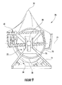
- Figures 9 shows an end view of the system 70 shown in Figure 7 .
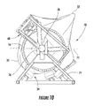
- the pivotal connection 72 supports the vertically oriented wind turbine blades 12, 14 slightly above the root cradles 34, 36. This allows the pivotal connection 72 to rotate the first and second wind turbine blades 12, 14 with respect to each other until each wind turbine blade is angled approximately 30 to 60 degrees with respect to the horizontal line 71, as shown in Figure 10 .
- the first and second wind turbine blades 12, 14 may be angled approximately 35 to 55 degrees, 40 to 50 degrees, or 45 degrees with respect to the horizontal line 71.
- the hinge pin 76 may be removed, and the shaft 78 lowered to allow the first and second wind turbine blades 12, 14 to rest in the first and second root cradles 34, 36, respectively.
- Figure 11 is a perspective view of the system 70 shown in Figure 10 loaded on the commercial carrier 62 for transport and/or storage.
- the first and second tip cradles 38, 40 and the first and second root cradles 34, 36 support the first and second wind turbine blades 12, 14 at an angle approximately 30 to 60 degrees with respect to the horizontal line 71.
- the system 70 arranges the first and second wind turbine blades 12, 14 approximately diagonally with respect to the horizontal line 71 to reduce width and height of the system 70 and wind turbine blades 12, 14 during transportation and/or storage.
- Figure 12 shows an end view of the system 70 (in phantom) and wind turbine blades 12, 14 shown in Figure 10 .
- the shipping area 64 is shown in Figure 12 as a dashed box circumscribing the outer perimeter of the system 70 and the wind turbine blades 12, 14. With the first and second wind turbine blades 12, 14 arranged approximately diagonally by the system 70, the shipping area 64 has a maximum width of 81 ⁇ 2 feet and a maximum height of 131 ⁇ 2 feet. It will be appreciated that the shipping area 64 defined by the system 70 and wind turbine blades 12, 14 may fit within or extend beyond the width and height of the commercial carrier 62. As a result, the system 70 arranges the wind turbine blades 12, 14 for transportation and/or storage without exceeding state and local transportation regulations regarding the maximum width and height of items transported on public roads.
- the system 70 described and shown in Figures 6-11 provides a method for arranging at least two wind turbine blades 12, 14 for transport and/or storage.
- the first wind turbine blade 12 may be transferred proximate to the first root cradle 34
- the second wind turbine blade 14 may be transferred proximate to the second root cradle 36.
- the clamp 56 or other suitable means for straightening at least one of the first or second wind turbine blades 12, 14, as shown in Figures 1 , 2 , and 3 may be used to straighten at least one of the wind turbine blades and move at least a portion of the first wind turbine blade 12 toward at least a portion of the second wind turbine blade 14.
- first and second wind turbine blades 12, 14 are oriented so that the convex surfaces 26 face one another, as shown in Figure 6 , one or more clamps 68 or other suitable means may be used to straighten at least one of the wind turbine blades and move at least a portion of the first wind turbine blade 12 toward at least a portion of the second wind turbine blade 14. At least a portion of the first and second wind turbine blades 12, 14 may be rotated about one another, as necessary, so that the first and second wind turbine blades rest 12, 14 in the respective root 34, 36 and tip 38, 40 cradles at an angle approximately 30 to 60 degrees with respect to the horizontal line 71. In particular embodiments, the first and second wind turbine blades 12, 14 may be angled approximately 35 to 55 degrees, 40 to 50 degrees, or 45 degrees with respect to the horizontal line 71.
Landscapes
- Engineering & Computer Science (AREA)
- Health & Medical Sciences (AREA)
- Public Health (AREA)
- Transportation (AREA)
- Mechanical Engineering (AREA)
- Wind Motors (AREA)
Abstract
Description
- The present invention generally involves wind turbine blades. In particular, the present invention discloses and enables systems and methods for arranging at least two wind turbine blades for storage and/or transport.
- Wind turbines are well known in the art for converting kinetic energy from the wind to mechanical or electrical energy, and wind turbine blades exist in various shapes and sizes. For example, some blades include a root at one end and a tip at the opposite end. The blade root attaches to a rotor, and the blade extends radially outward from the blade root to the blade tip. The blade may have a rounded or curved leading edge (i.e., the edge facing the direction of rotation) and a tapered or pointed trailing edge (i.e., the edge facing away from the direction of rotation), producing a blade with an aerodynamic or airfoil shape. In addition, the blade may be curved from the blade root to the blade tip, creating a convex surface on the top of the blade (i.e., the surface of the blade facing toward the oncoming wind) and a concave surface on the back of the blade (i.e., the surface of the blade facing away from the oncoming wind).
- The length, width, curvature, and weight of wind turbine blades varies, depending on the size of the wind turbine, anticipated wind speeds, and other design considerations. For example, wind turbine blades may extend greater than 100 feet, have an effective width of 9 feet or greater, curve more than 6 feet from blade root to blade tip, and weigh more than 13,000 pounds.
- State and local transportation regulations include limits regarding the maximum allowed width and height of items transported on public roads. For example, in the U.S., the maximum allowable width is typically 8½ feet, and the maximum allowable height ranges between 13½ and 14 feet, depending on the location. In Europe, the maximum allowable width is typically 11 feet 5 ¾ inches, and the maximum allowable height is 14 feet 7 inches. As a result, the size, shape, and weight of wind turbine blades generally requires that wind turbine blades be transported individually so as to not exceed the allowable size limits, increasing the cost of transporting wind turbine blades.
- Therefore, the need exists for an improved system and method for arranging wind turbine blades for transport and/or storage so that more than one wind turbine blade can be transported at the same time on public roads.
- Various aspects and advantages of the invention are set forth below in the following description, or may be obvious from the description, or may be learned through practice of the invention.
- In one embodiment of the present invention, a system for arranging first and second wind turbine blades includes a first root cradle and a second root cradle opposed to the first root cradle and separated from the first root cradle. The system further includes a first tip cradle proximate to the second root cradle, wherein the first tip cradle defines a first support plane angled approximately 30 to 60 degrees with respect to a horizontal line. The system also includes a second tip cradle proximate to the first root cradle, wherein the second tip cradle defines a second support plane angled approximately 30 to 60 degrees with respect to the horizontal line.
- Another embodiment of the present invention is a method for arranging at least two wind turbine blades. The method includes transferring a first wind turbine blade to a first root cradle and rotating the first wind turbine blade so that the first wind turbine blade is angled approximately 30 to 60 degrees with respect to a horizontal line. The method further includes transferring a second wind turbine blade to a second root cradle and rotating the second wind turbine blade so that the second wind turbine blade is angled approximately 30 to 60 degrees with respect to the horizontal line.
- Another method for arranging at least two wind turbine blades within the scope of the present invention includes transferring a first wind turbine blade to a first root cradle and transferring a second wind turbine blade to a second root cradle. The method further includes rotating at least a portion of the first wind turbine blade about at least a portion of the second wind turbine blade.
- Those of ordinary skill in the art will better appreciate the features and aspects of such embodiments, and others, upon review of the specification.
- Various aspects and embodiments of the present invention will now be described in connection with the accompanying drawings, in which:
-
Figure 1 is a perspective view of a system for arranging wind turbine blades according to one embodiment of the present invention; -
Figure 2 is a perspective view of the system and wind turbine blades shown inFigure 1 with the middle of the wind turbine blades drawn closer together; -
Figure 3 is a perspective view of the system and wind turbine blades shown inFigure 2 loaded on a commercial carrier; -
Figure 4 is an end view of the system and wind turbine blades shown inFigure 2 ; -
Figure 5 is a perspective view of a system for arranging wind turbine blades according to a second embodiment of the present invention; -
Figure 6 is a perspective view of a system for arranging wind turbine blades according to a third embodiment of the present invention; -
Figure 7 is a perspective view of the system shown inFigure 6 with the ends of the wind turbine blades drawn closer together; -
Figure 8 is an end view of a pivotal connection according to one embodiment of the present invention; -
Figure 9 is an end view of the system shown inFigure 7 with the wind turbine blades oriented in a substantially vertical position; -
Figure 10 is an end view of the system shown inFigure 7 with the wind turbine blades rotated approximately 30 to 60 degrees with respect to the horizon; -
Figure 11 is a perspective view of the system shown inFigure 10 loaded on a commercial carrier; and, -
Figure 12 is an end view of the system shown inFigure 10 . - Reference will now be made in detail to present embodiments of the invention, one or more examples of which are illustrated in the accompanying drawings. The detailed description uses numerical and letter designations to refer to features in the drawings. Like or similar designations in the drawings and description have been used to refer to like or similar parts of embodiments of the invention.
- Each example is provided by way of explanation of the invention, not as a limitation of the invention. In fact, it will be apparent to those skilled in the art that modifications and variations can be made in the present invention without departing from the scope or spirit thereof. For instance, features illustrated or described as part of one embodiment may be used on another embodiment to yield a still further embodiment. Thus, it is intended that the present invention covers such modifications and variations as come within the scope of the appended claims and their equivalents.
-
Figures 1 ,2 , and3 provide perspective views of asystem 10 for arranging first and secondwind turbine blades wind turbine blade blade root blade tip blade root studs 24, or other structure known in the art for attaching a wind turbine blade to a rotor of a wind turbine. Thewind turbine blades convex surface 26 on one side and aconcave surface 28 on the opposite side. In addition, thewind turbine blades wind turbine blades - The
wind turbine blades Figures 1 ,2 , and3 are arranged in an inverted position to one another with theconcave surfaces 28 facing one another and the leadingedges 30 down. As a result, eachblade root blade tip concave surfaces 28 create aspace 33 between the first and secondwind turbine blades - The
system 10 generally includes first andsecond root cradles second tip cradles first root cradle 34 and thefirst tip cradle 38 refer to the structures that support the firstwind turbine blade 12, and thesecond root cradle 36 and thesecond tip cradle 40 refer to the structures that support the secondwind turbine blade 14. As shown inFigures 1 ,2 , and3 , the first andsecond root cradles first tip cradle 38 is located closer to or proximate to thesecond root cradle 36 to support and cushion theblade tip 20 of the firstwind turbine blade 12, and thesecond tip cradle 40 is located closer to or proximate to thefirst root cradle 34 to support and cushion theblade tip 22 of the secondwind turbine blade 14. In particular embodiments, aframe 42 around the first andsecond root cradles first tip cradles Figures 1 and2 . In other particular embodiments, the tip cradles may be structurally separate from the proximate root cradles. - The
root cradles tip cradles cushions 44 or pads that form a seating surface which conforms to the exterior surface of the blade root or blade tip. The weight of thewind turbine blades cushions 44 holds thewind turbine blades cushions 44 or pads may be configured to completely or partially surround theblade roots blade tips strap 46, banding, or other suitable device may be used to hold thewind turbine blades - As illustrated in
Figure 2 , the first andsecond tip cradles second support planes horizontal line 49. In particular embodiments, the first andsecond support planes horizontal line 49. The first andsecond tip cradles second support planes second blade tips first root cradles cushions 44 or pads in the respective tip cradle, with or without a second surface opposed to the first surface. The second surface, if present, may includeadditional cushions 44 or pads, or the second surface may simply be astrap 46, banding, or other suitable devices to secure theblade tips - As shown in
Figures 1 ,2 , and3 , thesystem 10 further includes aclamp 56 between the first and second root cradles 34, 36 and near or proximate to the middle of the first and secondwind turbine blades Padded frames 58 may surround the first and secondwind turbine blades clamp 56 to the first and secondwind turbine blades clamp 56 may include aturnbuckle 60, winch, pulley, ram, or other equivalent device known to one of ordinary skill in the art to provide a mechanical advantage for moving at least a portion of the first and secondwind turbine blades clamp 56 to retract and move at least a portion of the first and secondwind turbine blades clamp 56 thus at least partially straightens one or both of thewind turbine blades space 33 between thewind turbine blades wind turbine blades -
Figure 2 shows the embodiment of thesystem 10 andwind turbine blades Figure 1 with theclamp 56 in a retracted position. As a result, the middle of the first and secondwind turbine blades space 33 between thewind turbine blades -
Figure 3 shows the embodiment of thesystem 10 andwind turbine blades Figures 1 and2 loaded on acommercial carrier 62 for transport and/or storage. The orientation of thesystem 10 andwind turbine blades Figure 3 has been reversed from that shown inFigures 1 and2 to show the opposite side of thesystem 10 not visible inFigures 1 and2 . As shown inFigure 3 , the first and second tip cradles 38, 40 and the first and second root cradles 34, 36 support the first and secondwind turbine blades horizontal line 49. In particular embodiments, the first and secondwind turbine blades horizontal line 49. As a result, thesystem 10 arranges thewind turbine blades horizontal line 49 to reduce the width and height of thesystem 10 andwind turbine blades -
Figure 4 shows an end view of the system 10 (in phantom) and wind turbine blades shown inFigure 2 . Ashipping area 64 for thesystem 10 and thewind turbine blades system 10 andwind turbine blades shipping area 64 is shown inFigure 4 as a dashed box circumscribing the outer perimeter of thesystem 10 andwind turbine blades wind turbine blades system 10, the shipping area has a maximum width of 8½ feet and a maximum height of 13½ feet. It will be appreciated that theshipping area 64 defined by thesystem 10 andwind turbine blades commercial carrier 62. As a result, thesystem 10 arranges thewind turbine blades -
Figure 5 provides a perspective view of asystem 66 for arranging the first and secondwind turbine blades commercial carrier 62 according to a second embodiment of the present invention. In this illustration, thewind turbine blades blade roots blade tips wind turbine blades Figures 1 ,2 , and3 . - The
wind turbine blades Figure 5 are arranged in an inverted position to one another with the leadingedges 30 down, similar to the orientation of thewind turbine blades Figures 1 ,2 , and3 . However, inFigure 5 , thewind turbine blades convex surfaces 26 face one another. As a result, the opposingconvex surfaces 26 are near or proximate to one another, and the curvature of thewind turbine blades blade root blade tip - The
system 66 shown inFigure 5 again includes first and second root cradles 34, 36 and first and second tip cradles 38, 40 which define first and second support planes as previously described and illustrated with respect to thesystem 10 shown inFigures 1 ,2 , and3 . In addition, thesystem 66 further includes one ormore clamps 68 near or proximate to the end of thewind turbine blades clamp 68 provides a means for straightening a wind turbine blade by moving a tip cradle and blade tip toward the proximate root cradle and blade root. For example, as shown inFigure 5 , theclamp 68 may be near or proximate to thefirst blade root 16,first root cradle 34,second blade tip 22, andsecond blade cradle 40. Theclamp 68 may connect to the first and secondwind turbine blades first blade root 16 and/orsecond blade tip 22 may be used to connect theclamp 68 directly to the first and secondwind turbine blades clamp 68 may connect indirectly to the first and secondwind turbine blades first root cradle 34 and thesecond tip cradle 40. Theclamp 68 may include a turnbuckle, winch, pulley, ram, or other equivalent device known to one of ordinary skill in the art to provide a mechanical advantage for moving the second tip cradle 40 (and second blade tip 22) toward the first root cradle 34 (and first blade root 16). For example, rotation of the turnbuckle may cause theclamp 68 to retract and move the second tip cradle 40 (and second blade tip 22) toward the first root cradle 34 (and first blade root 16). The retractedclamp 68 thus straightens the second 12 wind turbine blade to reduce the space between the second tip cradle 40 (and second blade tip 22) and the first root cradle 34 (and first blade root 16). Other suitable and equivalent means for straightening the wind turbine blades or moving at least a portion of one wind turbine blade toward the other wind turbine blade include counter-weights and/or hydraulic, pneumatic, or electromechanical presses. - The
system 66 shown inFigure 5 is appropriately used when thewind turbine blades convex surfaces 26 facing one another, and it provides the same beneficial reducedshipping area 64 as previously discussed with respect to thesystem 10 described and illustrated inFigures 1 ,2 , and3 . Specifically, with the first and secondwind turbine blades system 66, theshipping area 64 has a maximum width of 8½ feet and a maximum height of 13½ feet. As a result, thesystem 66 arranges thewind turbine blades - The two embodiments shown in
Figures 1-5 provide a method for arranging at least twowind turbine blades wind turbine blade 12 may be transferred proximate to thefirst root cradle 34. The firstwind turbine blade 12 may be rotated, as necessary, so that the firstwind turbine blade 12 rests in thefirst root cradle 34 and thefirst tip cradle 38 at an angle approximately 30 to 60 degrees with respect to thehorizontal line 49. The secondwind turbine blade 14 may be transferred proximate to thesecond root cradle 36. The secondwind turbine blade 14 may be rotated, as necessary, so that the secondwind turbine blade 14 rests in thesecond root cradle 36 and thesecond tip cradle 40 at an angle of approximately 30 to 60 degrees with respect to thehorizontal line 49. In particular embodiments, the first and secondwind turbine blades horizontal line 49. - If the first and second
wind turbine blades concave surfaces 28 face one another, theclamp 56 or other suitable means for straightening at least one of the first or secondwind turbine blades Figures 1 ,2 , and3 , may be used to straighten at least one of the wind turbine blades and move at least a portion of the firstwind turbine blade 12 toward at least a portion of the secondwind turbine blade 14. Alternatively, if the first and secondwind turbine blades convex surfaces 26 face one another, as shown inFigure 5 , one ormore clamps 68 or other suitable means may be used to straighten at least one of the wind turbine blades and move at least a portion of the firstwind turbine blade 12 toward at least a portion of the secondwind turbine blade 14. -
Figures 6 and7 provide perspective views of asystem 70 for arranging the first and secondwind turbine blades wind turbine blades blade roots blade tips wind turbine blades Figures 1 ,2 , and3 . - The
wind turbine blades Figures 6 and7 are arranged in an inverted position to one another with theconvex surfaces 26 facing one another and theleading edges 30 down. As a result, the opposingconvex surfaces 26 are near or proximate to one another, and the curvature of the wind turbine blades initially creates a space between eachblade root blade tip wind turbine blades horizontal line 71. - The
system 70 shown inFigures 6 and7 again includes first and second root cradles 34, 36 and first and second tip cradles 38, 40 which define first and second support planes as previously described and illustrated with respect to thesystem 10 shown inFigures 1 ,2 , and3 . However, because thewind turbine blades horizontal line 71, the first and second tip cradles 38, 40 and associated first and second support planes are also initially substantially vertical with respect to thehorizontal line 71. - The
system 70 shown inFigures 6 and7 additionally includes one ormore clamps 68 near or proximate to the end of thewind turbine blades system 66 shown inFigure 5 . Retraction of theclamps 68, as shown by the arrows inFigure 7 , straightens the first and secondwind turbine blades second blade tips 20, 22) and the proximate second/first root cradles 36, 34 (second/first blade roots 18, 16). - The
system 70 shown inFigures 6 and7 further includes apivotal connection 72 attached to theblade root wind turbine blade Figure 8 provides an end view of one embodiment of thepivotal connection 72 shown inFigures 6 and7 . As shown inFigure 8 , thepivotal connection 72 may include abracket 74, ahinge pin 76, and ashaft 78. Thebracket 74 andhinge pin 76 support theshaft 78 and allow theshaft 78 to freely rotate. Theshaft 78 connects to theblade root wind turbine blade wind turbine blades clamps 68. -
Figures 9 shows an end view of thesystem 70 shown inFigure 7 . As shown, thepivotal connection 72 supports the vertically orientedwind turbine blades pivotal connection 72 to rotate the first and secondwind turbine blades horizontal line 71, as shown inFigure 10 . In particular embodiments, the first and secondwind turbine blades horizontal line 71. When thewind turbine blades hinge pin 76 may be removed, and theshaft 78 lowered to allow the first and secondwind turbine blades -
Figure 11 is a perspective view of thesystem 70 shown inFigure 10 loaded on thecommercial carrier 62 for transport and/or storage. The first and second tip cradles 38, 40 and the first and second root cradles 34, 36 support the first and secondwind turbine blades horizontal line 71. As a result, thesystem 70 arranges the first and secondwind turbine blades horizontal line 71 to reduce width and height of thesystem 70 andwind turbine blades -
Figure 12 shows an end view of the system 70 (in phantom) andwind turbine blades Figure 10 . Theshipping area 64 is shown inFigure 12 as a dashed box circumscribing the outer perimeter of thesystem 70 and thewind turbine blades wind turbine blades system 70, theshipping area 64 has a maximum width of 8½ feet and a maximum height of 13½ feet. It will be appreciated that theshipping area 64 defined by thesystem 70 andwind turbine blades commercial carrier 62. As a result, thesystem 70 arranges thewind turbine blades - The
system 70 described and shown inFigures 6-11 provides a method for arranging at least twowind turbine blades wind turbine blade 12 may be transferred proximate to thefirst root cradle 34, and the secondwind turbine blade 14 may be transferred proximate to thesecond root cradle 36. If the first and secondwind turbine blades concave surfaces 28 face one another, theclamp 56 or other suitable means for straightening at least one of the first or secondwind turbine blades Figures 1 ,2 , and3 , may be used to straighten at least one of the wind turbine blades and move at least a portion of the firstwind turbine blade 12 toward at least a portion of the secondwind turbine blade 14. Alternatively, if the first and secondwind turbine blades convex surfaces 26 face one another, as shown inFigure 6 , one ormore clamps 68 or other suitable means may be used to straighten at least one of the wind turbine blades and move at least a portion of the firstwind turbine blade 12 toward at least a portion of the secondwind turbine blade 14. At least a portion of the first and secondwind turbine blades respective root tip horizontal line 71. In particular embodiments, the first and secondwind turbine blades horizontal line 71. - This written description uses examples to disclose the invention, including the preferred mode, and also to enable any person skilled in the art to practice the invention, including making and using any devices or systems and performing any incorporated methods. The patentable scope of the invention is defined by the claims, and may include other examples that occur to those skilled in the art. Such other examples are intended to be within the scope of the claims if they include structural elements that do not differ from the literal language of the claims, or if they include equivalent structural elements with insubstantial differences from the literal languages of the claims.
- Various aspects and embodiments of the present invention are defined by the following numbered clauses:
- 1. A system for arranging first and second wind turbine blades, comprising:
- a. a first root cradle;
- b. a second root cradle opposed to said first root cradle and separated from said first root cradle;
- c. a first tip cradle proximate to said second root cradle, wherein said first tip cradle defines a first support plane angled approximately 30 to 60 degrees with respect to a horizontal line; and,
- d. a second tip cradle proximate to said first root cradle, wherein said second tip cradle defines a second support plane angled approximately 30 to 60 degrees with respect to the horizontal line.
- 2. The system of clause 1, further including means for straightening at least one of the first or second wind turbine blades.
- 3. The system of any preceding clause, further including a clamp between said first and second root cradles and connected to the first and second wind turbine blades.
- 4. The system of any preceding clause, further including means for moving said second tip cradle toward said first root cradle.
- 5. The system of any preceding clause, further including a first clamp connected to said first root cradle and said second tip cradle.
- 6. The system of any preceding clause, further including a second clamp connected to said second root cradle and said first tip cradle.
- 7. The system of any preceding clause, further including a pivotal connection attached to the first and second wind turbine blades.
- 8. The system of any preceding clause, wherein at least one of said first support plane or said second support plane comprises a first surface and a second surface opposed to said first surface.
- 9. The system of any preceding clause, wherein said first and second root cradles and the first and second wind turbine blades define a shipping area having a width less than or equal to 8.5 feet.
- 10. The system of any preceding clause, wherein said first and second root cradles and the first and second wind turbine blades define a shipping area having a height less than or equal to 13.5 feet.
- 11. A method for arranging at least two wind turbine blades, comprising:
- a. transferring a first wind turbine blade to a first root cradle;
- b. rotating the first wind turbine blade so that the first wind turbine blade is angled approximately 30 to 60 degrees with respect to a horizontal line;
- c. transferring a second wind turbine blade to a second root cradle; and,
- d. rotating the second wind turbine blade so that the second wind turbine blade is angled approximately 30 to 60 degrees with respect to the horizon.
- 12. The method of any preceding clause, further including moving at least a portion of the first wind turbine blade toward at least a portion of the second wind turbine blade.
- 13. The method of any preceding clause, further including moving a tip of the first wind turbine blade toward a root of the second wind turbine blade.
- 14. The method of any preceding clause, further including moving a tip of the second wind turbine blade toward a root of the first wind turbine blade.
- 15. A method for arranging at least two wind turbine blades, comprising:
- a. transferring a first wind turbine blade to a first root cradle;
- b. transferring a second wind turbine blade to a second root cradle; and,
- c. rotating at least a portion of the first wind turbine blade about at least a portion of the second wind turbine blade.
- 16. The method of any preceding clause, further including moving at least a portion of the first wind turbine blade toward at least a portion of the second wind turbine blade.
- 17. The method of any preceding clause, further including moving a tip of the first wind turbine blade toward a root of the second wind turbine blade.
- 18. The method of any preceding clause, further including rotating at least a portion of the second wind turbine blade about at least a portion of the first wind turbine blade.
- 19. The method of any preceding clause, further including rotating a tip of the first wind turbine blade about a root of the second wind turbine blade.
- 20. The method of any preceding clause, further including rotating a tip of the second wind turbine blade about a root of the first wind turbine blade.
Claims (10)
- A system (10) for arranging first and second wind turbine blades (12, 14), comprising:a. a first root cradle (34);b. a second root cradle (36) opposed to said first root cradle (34) and separated from said first root cradle (34);c. a first tip cradle (38) proximate to said second root cradle (36), wherein said first tip cradle (38) defines a first support plane (48) angled approximately 30 to 60 degrees with respect to a horizontal line (49); and,d. a second tip cradle (40) proximate to said first root cradle (34), wherein said second tip cradle (40) defines a second support plane (50) angled approximately 30 to 60 degrees with respect to the horizontal line (49).
- The system (10) as in claim 1, further including means for straightening at least one of the first or second wind turbine blades (12, 14).
- The system (10) as in any of claims 1-2, further including means for moving said second tip cradle (40) toward said first root cradle (34).
- The system (10) as in any of claims 1-3, further including a pivotal connection (72) attached to the first and second wind turbine blades (12, 14).
- The system (10) as in any of claims 1-4, wherein said first and second root cradles (34, 36) and the first and second wind turbine blades (12, 14) define a shipping area (64) having a width less than or equal to 8.5 feet.
- The system (10) as in any of claims 1-5, wherein said first and second root cradles (34, 36) and the first and second wind turbine blades (12, 14) define a shipping area (64) having a height less than or equal to 13.5 feet.
- A method for arranging at least two wind turbine blades, comprising:a transferring a first wind turbine blade (12) to a first root cradle (34);b. rotating the first wind turbine blade (12) so that the first wind turbine blade (12) is angled approximately 30 to 60 degrees with respect to a horizontal line (49);c. transferring a second wind turbine blade (14) to a second root cradle (36); and,d. rotating the second wind turbine blade (14) so that the second wind turbine blade (36) is angled approximately 30 to 60 degrees with respect to the horizon.
- The method as in claim 7, further including moving at least a portion of the first wind turbine blade (12) toward at least a portion of the second wind turbine blade (14).
- The method as in any of claims 7-8, further including moving a tip (20) of the first wind turbine blade (12) toward a root (18) of the second wind turbine blade (14).
- The method as in any of claims 7-9, further including moving a tip (22) of the second wind turbine blade (14) toward a root (16) of the first wind turbine blade (12).
Applications Claiming Priority (1)
| Application Number | Priority Date | Filing Date | Title |
|---|---|---|---|
| US12/632,231 US8511921B2 (en) | 2009-12-07 | 2009-12-07 | System and method for arranging wind turbine blades |
Publications (2)
| Publication Number | Publication Date |
|---|---|
| EP2333315A2 true EP2333315A2 (en) | 2011-06-15 |
| EP2333315A3 EP2333315A3 (en) | 2016-09-28 |
Family
ID=43770584
Family Applications (1)
| Application Number | Title | Priority Date | Filing Date |
|---|---|---|---|
| EP10191953.8A Withdrawn EP2333315A3 (en) | 2009-12-07 | 2010-11-19 | System and method for arranging wind turbine blades |
Country Status (3)
| Country | Link |
|---|---|
| US (1) | US8511921B2 (en) |
| EP (1) | EP2333315A3 (en) |
| CN (1) | CN102092537B (en) |
Cited By (8)
| Publication number | Priority date | Publication date | Assignee | Title |
|---|---|---|---|---|
| DE102011113482A1 (en) | 2011-09-13 | 2013-03-14 | Nordex Energy Gmbh | Protective device for a rotor blade of a wind energy plant |
| EP2669507A1 (en) * | 2012-06-01 | 2013-12-04 | Siemens Aktiengesellschaft | Transportation and stacking of curved blades lying oppositely and above each other |
| WO2014064246A1 (en) * | 2012-10-26 | 2014-05-01 | Lm Wp Patent Holding A/S | Method and system for transporting and storing at least two wind turbine blades |
| WO2014064247A1 (en) * | 2012-10-26 | 2014-05-01 | Lm Wp Patent Holding A/S | Method and system for transporting and storing at least two wind turbine blades |
| WO2018041993A1 (en) * | 2016-09-02 | 2018-03-08 | Lm Wind Power International Technology Ii Aps | Transportation and storage system for a wind turbine blade |
| EP3620651A4 (en) * | 2018-06-28 | 2020-07-29 | Jiangsu Goldwind Science & Technology Co., Ltd. | BLADE TRANSPORT HOLDER |
| EP3169893B1 (en) | 2014-07-17 | 2021-01-13 | LM WP Patent Holding A/S | Modular system for transporting wind turbine blades |
| EP3718823B1 (en) | 2019-04-01 | 2023-05-31 | Scheuerle Fahrzeugfabrik GmbH | Device for holding an end of an elongated object, in particular a self-supporting load, and vehicle using this device |
Families Citing this family (12)
| Publication number | Priority date | Publication date | Assignee | Title |
|---|---|---|---|---|
| US8342491B2 (en) * | 2009-04-01 | 2013-01-01 | Vestas Wind Systems A/S | Transport system for transportation of a spar |
| DK2441950T3 (en) * | 2010-10-15 | 2014-06-10 | Alstom Renovables Espana Sl | Wing for a wind turbine |
| US20120201636A1 (en) * | 2011-02-07 | 2012-08-09 | Vestas Wind Systems A/S | Transportation device for a wind turbine component and method of using same |
| DK177951B1 (en) * | 2013-03-01 | 2015-02-02 | Envision Energy Denmark Aps | Two or three wind turbine blades as one unit |
| ES2784679T3 (en) * | 2013-09-16 | 2020-09-29 | Vestas Wind Sys As | Transportation and stacking of wind turbine blades |
| DK2857675T3 (en) * | 2013-10-07 | 2017-02-27 | Siemens Ag | Design of a curved rotor blade |
| GB201523123D0 (en) * | 2015-12-30 | 2016-02-10 | Vestas Wind Sys As | Transport frame for a wind turbine blade |
| EP3217011B1 (en) * | 2016-03-11 | 2020-11-18 | LM WP Patent Holding A/S | System for transport and/or storage of wind turbine blade shell half parts and related method |
| US10697437B1 (en) * | 2019-08-27 | 2020-06-30 | Bnsf Logistics, Llc | Rotatable support fixture for wind turbine blade |
| EP3885576A1 (en) * | 2020-03-27 | 2021-09-29 | Siemens Gamesa Renewable Energy A/S | Wind turbine component transport arrangement |
| CN113830428A (en) * | 2021-08-25 | 2021-12-24 | 南通艾郎风电科技发展有限公司 | Method for transferring and stacking large blades |
| CN114906483B (en) * | 2022-06-21 | 2023-05-16 | 江苏振江新能源装备股份有限公司 | Loading method for wind driven generator bracket |
Family Cites Families (12)
| Publication number | Priority date | Publication date | Assignee | Title |
|---|---|---|---|---|
| US2335692A (en) | 1943-01-30 | 1943-11-30 | Thomas W Murray | Supporting table and jack |
| US2725241A (en) | 1952-02-28 | 1955-11-29 | Jr Talbert A Leonard | Wing carrying device for transporting aircraft wings |
| US2808288A (en) | 1954-01-25 | 1957-10-01 | Spencer Safford Loadcraft Inc | Vehicle transportation and storage capsule |
| US5683213A (en) | 1996-04-29 | 1997-11-04 | High Concrete Structures, Inc. | Loading fixture |
| GB0109515D0 (en) | 2001-04-17 | 2001-06-06 | Neg Micon As | A method for transporting a set of large longitudinal items, a package system to be used by the method and use of such a package system |
| US20030175089A1 (en) | 2002-03-13 | 2003-09-18 | Preben Almind | Transport container for wind turbine blades |
| DK177128B1 (en) | 2003-07-10 | 2011-12-19 | Lm Glasfiber As | Transport and storage of cranked wind turbine blades |
| BRPI0405546F1 (en) * | 2004-12-10 | 2016-03-22 | Tecsis Tecnologia E Sist S Avançados Ltda | joint development of structures for handling, transporting and storing blades for wind turbine rotors |
| US20070177954A1 (en) * | 2006-01-31 | 2007-08-02 | General Electric Company | Method and apparatus for containing and/or transporting rotor blades |
| US7713007B2 (en) | 2007-05-31 | 2010-05-11 | General Electric Company | Method and apparatus for containing, storing and/or transporting curved wind turbine rotor blades |
| US8240962B2 (en) * | 2007-12-28 | 2012-08-14 | General Electric Company | Integrated shipping fixture and assembly method for jointed wind turbine blades |
| US7967536B2 (en) | 2008-05-02 | 2011-06-28 | Gamesa Innovation & Technology, S.L. | Blade transportation |
-
2009
- 2009-12-07 US US12/632,231 patent/US8511921B2/en active Active
-
2010
- 2010-11-19 EP EP10191953.8A patent/EP2333315A3/en not_active Withdrawn
- 2010-12-07 CN CN201010592412.0A patent/CN102092537B/en active Active
Non-Patent Citations (1)
| Title |
|---|
| None |
Cited By (17)
| Publication number | Priority date | Publication date | Assignee | Title |
|---|---|---|---|---|
| DE102011113482A1 (en) | 2011-09-13 | 2013-03-14 | Nordex Energy Gmbh | Protective device for a rotor blade of a wind energy plant |
| EP2570654A2 (en) | 2011-09-13 | 2013-03-20 | Nordex Energy GmbH | Protective device for a blade of a wind turbine |
| DE102011113482B4 (en) * | 2011-09-13 | 2013-04-18 | Nordex Energy Gmbh | Protective device for a rotor blade of a wind energy plant |
| EP2669507A1 (en) * | 2012-06-01 | 2013-12-04 | Siemens Aktiengesellschaft | Transportation and stacking of curved blades lying oppositely and above each other |
| US10781834B2 (en) | 2012-10-26 | 2020-09-22 | Lm Wp Patent Holding A/S | Method and system for transporting and storing at least two wind turbine blades |
| WO2014064247A1 (en) * | 2012-10-26 | 2014-05-01 | Lm Wp Patent Holding A/S | Method and system for transporting and storing at least two wind turbine blades |
| US9709025B2 (en) | 2012-10-26 | 2017-07-18 | Lm Wp Patent Holding A/S | Method and system for transporting and storing at least two wind turbine blades |
| US9874235B2 (en) | 2012-10-26 | 2018-01-23 | Lm Wp Patent Holding A/S | Method and system for transporting and storing at least two wind turbine blades |
| US10589941B2 (en) | 2012-10-26 | 2020-03-17 | LM WP Patent Holdings A/S | Method and system for transporting and storing at least two wind turbine blades |
| WO2014064246A1 (en) * | 2012-10-26 | 2014-05-01 | Lm Wp Patent Holding A/S | Method and system for transporting and storing at least two wind turbine blades |
| EP2912305B1 (en) | 2012-10-26 | 2021-03-03 | LM WP Patent Holding A/S | Method and system for transporting and storing at least two wind turbine blades |
| EP3169893B1 (en) | 2014-07-17 | 2021-01-13 | LM WP Patent Holding A/S | Modular system for transporting wind turbine blades |
| WO2018041993A1 (en) * | 2016-09-02 | 2018-03-08 | Lm Wind Power International Technology Ii Aps | Transportation and storage system for a wind turbine blade |
| US10731634B2 (en) | 2016-09-02 | 2020-08-04 | Lm Wind Power Us Technology Aps | Transportation and storage system for a wind turbine blade |
| EP3620651A4 (en) * | 2018-06-28 | 2020-07-29 | Jiangsu Goldwind Science & Technology Co., Ltd. | BLADE TRANSPORT HOLDER |
| US11486363B2 (en) | 2018-06-28 | 2022-11-01 | Jiangsu Goldwind Science & Technology Co., Ltd. | Blade transport holder |
| EP3718823B1 (en) | 2019-04-01 | 2023-05-31 | Scheuerle Fahrzeugfabrik GmbH | Device for holding an end of an elongated object, in particular a self-supporting load, and vehicle using this device |
Also Published As
| Publication number | Publication date |
|---|---|
| CN102092537B (en) | 2016-01-06 |
| EP2333315A3 (en) | 2016-09-28 |
| US8511921B2 (en) | 2013-08-20 |
| CN102092537A (en) | 2011-06-15 |
| US20110131809A1 (en) | 2011-06-09 |
Similar Documents
| Publication | Publication Date | Title |
|---|---|---|
| US8511921B2 (en) | System and method for arranging wind turbine blades | |
| EP2330291A2 (en) | System and method for arranging wind turbine blades | |
| US8562302B2 (en) | Wind turbine blade with integrated handling mechanism attachment bores | |
| CN106536919B (en) | Modular system for transporting wind turbine blades | |
| EP1644271B1 (en) | Transporting and storing curved wind turbine blades | |
| CN101314428B (en) | Method and apparatus for containing, storing and/or transporting curved wind turbine rotor blades | |
| EP2075467A2 (en) | Integrated shipping fixture and assembly method for jointed wind turbine blades | |
| US10781834B2 (en) | Method and system for transporting and storing at least two wind turbine blades | |
| US20110308205A1 (en) | Three aerogenerator blades packing system (packing method and packing system for three aerogenerator blades) | |
| CN104214053A (en) | System and method of moving a wind turbine rotor blade | |
| AU2012264751B2 (en) | Wind turbine rotor blade and method for installing a wind turbine rotor blade | |
| EP2669507A1 (en) | Transportation and stacking of curved blades lying oppositely and above each other | |
| EP2772390A2 (en) | Two or three wind turbine blades as one unit | |
| EP2669506A1 (en) | Handling of curved blades with displaced opposite root ends during stacking | |
| CN103318568B (en) | A kind of transportation resources of blades of large-scale wind driven generator | |
| CN217538904U (en) | Blades and Wind Turbines | |
| CN108482692B (en) | An unmanned helicopter rotor retractable device | |
| CN208218178U (en) | Hoisting fan blade protective device | |
| DK201771039A1 (en) | Methods and apparatus for handling wind turbine blades |
Legal Events
| Date | Code | Title | Description |
|---|---|---|---|
| PUAI | Public reference made under article 153(3) epc to a published international application that has entered the european phase |
Free format text: ORIGINAL CODE: 0009012 |
|
| AK | Designated contracting states |
Kind code of ref document: A2 Designated state(s): AL AT BE BG CH CY CZ DE DK EE ES FI FR GB GR HR HU IE IS IT LI LT LU LV MC MK MT NL NO PL PT RO RS SE SI SK SM TR |
|
| AX | Request for extension of the european patent |
Extension state: BA ME |
|
| PUAL | Search report despatched |
Free format text: ORIGINAL CODE: 0009013 |
|
| AK | Designated contracting states |
Kind code of ref document: A3 Designated state(s): AL AT BE BG CH CY CZ DE DK EE ES FI FR GB GR HR HU IE IS IT LI LT LU LV MC MK MT NL NO PL PT RO RS SE SI SK SM TR |
|
| AX | Request for extension of the european patent |
Extension state: BA ME |
|
| RIC1 | Information provided on ipc code assigned before grant |
Ipc: F03D 1/00 20060101AFI20160825BHEP Ipc: B60P 3/40 20060101ALI20160825BHEP |
|
| 17P | Request for examination filed |
Effective date: 20170328 |
|
| RBV | Designated contracting states (corrected) |
Designated state(s): AL AT BE BG CH CY CZ DE DK EE ES FI FR GB GR HR HU IE IS IT LI LT LU LV MC MK MT NL NO PL PT RO RS SE SI SK SM TR |
|
| GRAP | Despatch of communication of intention to grant a patent |
Free format text: ORIGINAL CODE: EPIDOSNIGR1 |
|
| INTG | Intention to grant announced |
Effective date: 20170727 |
|
| STAA | Information on the status of an ep patent application or granted ep patent |
Free format text: STATUS: THE APPLICATION IS DEEMED TO BE WITHDRAWN |
|
| 18D | Application deemed to be withdrawn |
Effective date: 20171207 |
|
| P01 | Opt-out of the competence of the unified patent court (upc) registered |
Effective date: 20230522 |