EP2333299A1 - Pipe fastening structure - Google Patents
Pipe fastening structure Download PDFInfo
- Publication number
- EP2333299A1 EP2333299A1 EP10191796A EP10191796A EP2333299A1 EP 2333299 A1 EP2333299 A1 EP 2333299A1 EP 10191796 A EP10191796 A EP 10191796A EP 10191796 A EP10191796 A EP 10191796A EP 2333299 A1 EP2333299 A1 EP 2333299A1
- Authority
- EP
- European Patent Office
- Prior art keywords
- metal pipe
- pipe
- end member
- nut
- fastening structure
- Prior art date
- Legal status (The legal status is an assumption and is not a legal conclusion. Google has not performed a legal analysis and makes no representation as to the accuracy of the status listed.)
- Granted
Links
Images


Classifications
-
- F—MECHANICAL ENGINEERING; LIGHTING; HEATING; WEAPONS; BLASTING
- F16—ENGINEERING ELEMENTS AND UNITS; GENERAL MEASURES FOR PRODUCING AND MAINTAINING EFFECTIVE FUNCTIONING OF MACHINES OR INSTALLATIONS; THERMAL INSULATION IN GENERAL
- F16L—PIPES; JOINTS OR FITTINGS FOR PIPES; SUPPORTS FOR PIPES, CABLES OR PROTECTIVE TUBING; MEANS FOR THERMAL INSULATION IN GENERAL
- F16L19/00—Joints in which sealing surfaces are pressed together by means of a member, e.g. a swivel nut, screwed on, or into, one of the joint parts
- F16L19/02—Pipe ends provided with collars or flanges, integral with the pipe or not, pressed together by a screwed member
- F16L19/025—Pipe ends provided with collars or flanges, integral with the pipe or not, pressed together by a screwed member the pipe ends having integral collars or flanges
-
- F—MECHANICAL ENGINEERING; LIGHTING; HEATING; WEAPONS; BLASTING
- F02—COMBUSTION ENGINES; HOT-GAS OR COMBUSTION-PRODUCT ENGINE PLANTS
- F02M—SUPPLYING COMBUSTION ENGINES IN GENERAL WITH COMBUSTIBLE MIXTURES OR CONSTITUENTS THEREOF
- F02M55/00—Fuel-injection apparatus characterised by their fuel conduits or their venting means; Arrangements of conduits between fuel tank and pump F02M37/00
- F02M55/004—Joints; Sealings
- F02M55/005—Joints; Sealings for high pressure conduits, e.g. connected to pump outlet or to injector inlet
-
- F—MECHANICAL ENGINEERING; LIGHTING; HEATING; WEAPONS; BLASTING
- F16—ENGINEERING ELEMENTS AND UNITS; GENERAL MEASURES FOR PRODUCING AND MAINTAINING EFFECTIVE FUNCTIONING OF MACHINES OR INSTALLATIONS; THERMAL INSULATION IN GENERAL
- F16L—PIPES; JOINTS OR FITTINGS FOR PIPES; SUPPORTS FOR PIPES, CABLES OR PROTECTIVE TUBING; MEANS FOR THERMAL INSULATION IN GENERAL
- F16L19/00—Joints in which sealing surfaces are pressed together by means of a member, e.g. a swivel nut, screwed on, or into, one of the joint parts
- F16L19/02—Pipe ends provided with collars or flanges, integral with the pipe or not, pressed together by a screwed member
- F16L19/0212—Pipe ends provided with collars or flanges, integral with the pipe or not, pressed together by a screwed member using specially adapted sealing means
- F16L19/0225—Pipe ends provided with collars or flanges, integral with the pipe or not, pressed together by a screwed member using specially adapted sealing means without sealing rings
Definitions
- the present invention relates to a pipe fastening structure for use in a fuel line on an internal combustion engine, such as a diesel or a gasoline engine. More particularly, the present invention relates to a pipe fastening structure for fastening a spherical end of an end member attached to an end part of a metal pipe to a counterpart with a nut.
- a fuel line on an internal combustion engine such as a diesel or a gasoline engine, includes a metal pipe having a spherical end for carrying high-pressure fuel.
- the spherical end of the metal pipe is fastened to a counterpart on the engine by a pipe fastening structure including a nut for fastening the spherical end to the counterpart on the engine.
- Fuel leakage can be surely prevented by pressing the spherical end of the metal pipe against a seat formed in the counterpart on the engine by the nut of the pipe fastening structure.
- the pipe fastening structure has been widely used in high-pressure fuel lines.
- pipe fastening structures disclosed in Patent documents 1, 2 and 3 are representative prior art pipe fastening structures.
- each of the prior art pipe fastening structures includes a sleeve (or a washer) placed between a nut and a spherical end.
- the sleeve is effective in applying high pressure to the spherical end to press the spherical end against the seat of a counterpart.
- the sleeve is thus used, local pressure reduction can be avoided and stable sealing can be achieved even if the nut is fastened with the respective axes of the spherical end and the counterpart are slightly misaligned because the respective axes of the spherical end and the sleeve are aligned.
- a reduced part having an inside diameter smaller than that of an outer part of the nut is formed in the inside surface of a part of the nut near the outer end of the nut.
- a shoulder that comes into contact with the outer end of the counterpart defining the open end of the sealing surface of the counterpart is formed at the boundary between the first and the second spherical part.
- a second shoulder with which an outer end of the first spherical part is brought into contact is formed in an open end part of the sealing surface of the counterpart.
- the inside surface of an end part of the first spherical part is protruded inward to form a thick end.
- the end member is welded or brazed to an end part of the metal pipe, and the outside surface of the joint of the end member, and metal pipe is flush with the outside surface of the metal pipe.
- the end member is formed by subjecting an end part of the metal pipe to press working.
- the metal pipe, the nut and the counterpart are made of stainless steels, respectively.
- the respective centers of spheres respectively defining the first and the second spherical parts are at the same point on the axis of the neck.
- the sliding surface of the nut has a hardness higher than that of the surface of the second spherical part.
- the sliding surface of the nut and the sealing surface of the counterpart are coated with oil.
- the respective centers of spheres respectively defining the first and the second spherical parts are at the same point on the axis of the neck.
- the diameter of the sphere defining the first spherical part is smaller than that of the sphere defining the second spherical part.
- the metal pipe and the end member are joined such that a joining part of the metal pipe and a joining part of the end member overlap each other, the joining part of the metal pipe is fitted in the joining part of the end member, the outside surface of the metal pipe is flush with the outside surface of the joining part of the end member, and the inside surface of the joining part of the metal pipe is flush with the inside surface of the end member.
- the metal pipe and the end member are joined together such that the respective joining part of the metal pipe and the end member overlap each other, the joining part of the end member is fitted in the joining part of the metal pipe, the outside surface of the joining part of the metal pipe is flush with the outside surface of the end member, and the inside surface of the metal pipe is flush with the inside surface of the joining part of the end member.
- the end part of the metal pipe and the nut do not turn together relative to the counterpart even if a toque necessary for producing a desired axial force is applied to the nut, so that damage to the sealing surface and the sliding surface can be prevented.
- a metal pipe 10 a nut 12, and a counterpart 14 to which the metal pipe 10 is to be fastened.
- the pipe fastening structure includes an end member 16 attached to an end part of the metal pipe 10, and the nut 12 for fastening the end member 16 to the counterpart 14.
- the counterpart 14 is a pipe joint.
- the end member 16 having spherical parts is attached to the end part of the metal pipe 10.
- the end member 16 is pressed directly against the counterpart 14 with the nut 12.
- This pipe fastening structure differs from the prior art pipe connector in that any part such as a sleeve or a washer, is not placed between the nut 12 and the end member 16.
- a joining part 17 is formed in an end part of the metal pipe 10.
- the end member 16 has a generally spherical bulged part having a first spherical part 20 and a second spherical part 21, and a neck 18 having the shape of a straight pipe and extending from the bulged part.
- the respective centers of spheres respectively defining the first spherical part 20 and the second spherical part 21 are on the axis of the neck 18.
- a joining part 19 is formed in the neck 18.
- the joining part 17 of the metal pipe 10 is fitted in the bore of the joining part 19.
- the joining part 19 surrounds the joining part 17 and is welded or brazed to the joining part 17.
- the outside diameter D 1 of the neck 18 is equal to the outside diameter D of the metal pipe 10 or substantially equal to the outside diameter D of the metal tube 10 with an error within a tolerance.
- the outside surface of the neck 18 is flush with that of the metal pipe 10.
- the outside surface of the metal pipe 10 is flush with that of the joining part 19, and the inside surface of the joining part 17 of the metal pipe 10 is flush with the inside surface of the end member 16.
- a through hole 23 is formed in the end wall of the nut 12. The diameter of the through hole 23 is slightly greater than the outside diameter D of the metal pipe 10.
- the neck 18 of the end member 16 is extended loosely through the through hole 23.
- a taper surface tapering toward the through hole 23 and a internal thread 24 are formed in the inside surface of the nut 12. The taper surface serves as a sliding surface 25 to be brought into contact with the second spherical part 21 of the end member 16.
- An external thread 26 capable of mating with the internal thread 24 of the nut 12 is formed in the outside surface of a joining part of the counterpart 14.
- a tapered sealing surface 27 is formed in the end part of the counterpart 14. The first spherical part 20 of the end member 16 is brought into contact with the sealing surface 27.
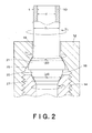
- Fig. 2 is a longitudinal sectional view of the pipe fastening structure shown in Fig. 1 , indicating dimensions of parts of the pipe fastening structure, and forces that act on parts of the pipe fastening structure when the nut 12 is fastened.
- the metal pipe 10 has the outside diameter D, an inside diameter d and a wall thickness t.
- a contact circle on the first spherical part 20 in contact with the sealing surface 27 has a diameter D 2
- a contact circle on the second spherical part 21 in contact with the sliding surface 25 has a diameter D 3 .
- the first spherical part 20 and the second spherical part 21 are defined by spheres respectively having different diameters and having the same centers O as shown in Fig. 3 .
- the radius of the sphere defining the second spherical part 21 is greater than that of the sphere defining the first spherical part 20.
- the centers O of the spheres respectively defining the first spherical part 20 and the second spherical part 21 are not necessarily at the same point on the axis of the neck 18.
- the ratio a D 2 /D, where D 2 is the diameter of the contact circle on the first spherical part 20 in contact with the sealing surface 27 and D is the outside diameter of the metal pipe 10
- Fig. 3 is a half sectional view showing components of forces that act on parts of the pipe fastening structure when the nut 12 is fastened.
- F is an axial force that presses the end member 16 against the sealing surface 27 of the counterpart 14 when the nut 12 is fastened.
- an axial force f 1 acts on a unit length of the contact circle on the first spherical part 20 in contact with the sealing surface 27, and an axial force f 2 acts on a unit length of the contact circle on the second spherical part 21 in contact with the sliding surface 25 of the nut 12.
- a normal component force acting on a point on the first spherical part 20 in contact with the sealing surface 27 is N 1
- the angle between a tangent at the contact point on the first spherical part 20 in contact with the sealing surface 27 and the axis is ⁇ 1
- a normal component force acting on a point on the second spherical part 21 in contact with the sliding surface 25 is N 2
- the angle between a tangent at the contact point on the second spherical part 21 in contact with the sliding surface 25 and the axis is ⁇ 2 .
- N 1 f 1 ⁇ sin ⁇ 1
- N 2 f 2 ⁇ sin ⁇ 2
- Torsional rigidity of the metal pipe 10 having the inside diameter d and the outside diameter D is expressed by the following expressions.
- T max T 3 / Z p
- D ⁇ max ⁇ ⁇ ⁇ D 3 ⁇ 1 - ⁇ 4 ) / 16
- Z p is the torsion section modulus.
- Z p ⁇ (D 4 -d 4 )/16D.
- T T 3 /Z p , where T is shearing stress. It is supposed that the maximum shearing stress T max is the maximum value of the shearing stress T.
- Expression (2) is obtained by substituting those expressions into Expression (1). ⁇ F ⁇ D / 2 ⁇ sin ⁇ 1 ⁇ ⁇ F ⁇ D / 2 ⁇ sin ⁇ 2 - ⁇ max ⁇ ⁇ D 3 ⁇ 1 - ⁇ 4 / 16
- the left side of Expression (2) represents frictional torque T 1
- the first member of the right side represents fastening torque T 2
- the second member of the right side represents torsional countertorque T 3 produced by the torsional rigidity of the metal pipe 10.
- the frictional torque T 1 is proportional to the force F.
- the fastening torque T 2 is proportional to the force F
- the torsional countertorque T 3 produced by the torsional rigidity is a constant dependent on the shape and the material of the metal pipe 10.
- the metal pipe 10 having characteristics perfectly meeting the condition expressed by Expression (2) can surely avoid being dragged for turning when the nut 12 fastens the end member 16 to the counterpart 14.
- a D 2 /D. Practically, the value of the ratio a is in the range of 0.9 to 1.1 as obvious from Fig. 2 . It is supposed that the ratio a is approximately equal to 1.
- Figs. 4 to 7 show results of analysis of variations of the frictional torque T 1 , and the difference between the fastening torque T 2 and the torsional countertorque T 3 (T 2 - T 3 ) for metal pipes 10 having different outside diameters D and different wall thicknesses t.
- Fig. 4 the variation of the frictional torque T 1 with the axial force is indicated by a thick straight line.
- T 2 - T 3 is greater than the frictional torque T 1 in a range of the axial force F excluding a range of the axial force F in which the axial force F is very low and Expression (2) is not satisfied.
- This condition will be explained in connection with Fig. 2 .
- the diameter D 3 of the contact circle on the second spherical part 21 in contact with the sliding surface 25 is considerably greater than the diameter D 2 of the contact circle on the first spherical part 20 in contact with the sealing surface 27, the torque exerted on the end member 16 by the nut 12 is higher than the frictional countertorque exerted on the end member 16 by the sealing surface 27. Consequently, the end member 16 will be dragged for turning by the nut 12.
- the fastening axial force F is, as mentioned above, on the order of 5 kN at the maximum.
- the axial force F is in the range of about 3 to about 4 kN.
- the end member 16 will not be practically dragged for turning by the nut 12 when a/ ⁇ > 0.78.
- a value of the ratio a/ ⁇ greater than 1 signifies that the sphere defining the first spherical part 20 is larger than that defining the second spherical part 21.
- a pipe fastening structure having a first spherical part 20 larger than a second spherical part 21 due to restrictive conditions of the counterpart 14.
- the maximum value of the ratio a/ ⁇ is 1, which signifies that the diameter D 2 of the contact circle on the first spherical part 20 in contact with the sealing surface 27 is equal to the diameter D 3 of the contact circle on the second spherical part 21 in contact with the sliding surface 25.
- the ratio a/ ⁇ effective in preventing the metal pipe 10 from being draggedfor turning when the metal pipe 10 has an outside diameter D of 8 mm and a wall thickness t of 1.2 mm determined from Fig. 5 by a procedure taken for determining the values of the ratio a/ ⁇ from Fig. 4 is expressed by: ⁇ / ⁇ ⁇ 0.80
- the ratio a/ ⁇ effective in preventing the dragged turning of the metal pipe 10 when the metal pipe 10 has an outside diameter D of 9.53 mm and a wall thickness t of 1.2 mm determined from Fig. 6 is: ⁇ / ⁇ ⁇ 0.75
- the ratio a/ ⁇ is expressed by: ⁇ / ⁇ ⁇ 0.72
- a range of values of the ratio a/ ⁇ is expressed by: 1.0 ⁇ ⁇ / ⁇ ⁇ 0.80 Practically, the dragging of the end member 16 for turning by the nut 12 can be suppressed when the ratio a/ ⁇ satisfies Expression (3).
- the hardness of the sliding surface 25 of the nut 12 is higher than that of the surface of the second spherical part 21 of the end member 16.
- the sliding surface 25 of the nut 12 is harder than the surface of the second spherical part 21 and the nut 12 and the second spherical part 21 are in line contact with each other, the nut 12 will not be galled, the line contact between the nut 12 and the second spherical part 21 is maintained even if the contact surface of the second spherical part 21 is galled, and torque necessary for producing a desired axial force F does not increase.
- the sliding surface 25 or the surface of the second spherical part 21, and the surface of the first spherical part 20 are coated with oil to avoid seizing.
- Fig. 8 shows a pipe fastening structure in a second embodiment according to the present invention.
- the second and third to sixth embodiments are similar to the first embodiment in that the ratio of the ratio a for determining the diameter D 2 of the contact circle on the first spherical part 20 in contact with the sealing surface 27 of the counterpart 14 to the ratio ⁇ for determining the diameter D 3 of a contact surface on the second spherical part 21 in contact with the sliding surface 25, namely, a/ ⁇ , is supposed to meet a expressiion: 1.0 ⁇ ⁇ / ⁇ ⁇ 0.80
- the diameter of a part of the inside surface of an outer part of a nut 12 is reduced to form a reduced part 30.
- the reduced part 30 is formed on the inside surface of the nut 12 defining a through hole 23 in the nut 12.
- the surface of the reduced part 30 merges into a sliding surface 25.
- the reduced part 30 brings a contact circle on a second spherical part 21 of an end member 16 into contact with the sliding surface 25 at a position near a neck 18. Consequently, the diameter D 3 of the contact circle on the second spherical part 21 is small and the ratio ⁇ is diminished and approaches the ratio a. Thus, the condition expressed by Expression (3) can be easily satisfied.
- the end member 16 can be fastened to the counterpart 14 even if the neck 18 is tilted relative to the counterpart 14 or the metal pipe 10 is joined somewhat incorrectly to the neck 18.
- Fig. 9 shows a pipe fastening structure in a third embodiment according to the present invention.
- an end member 16 is provided with a shoulder 32 at the boundary between a first spherical part 20 and a second spherical part 21.
- the shoulder 32 is brought into contact with the end surface of a counterpart 14 continuous with a sealing surface 27 formed in the counterpart 14.
- the shoulder 32 of the end member 16 is pressed against the end surface of the counterpart 14 when a nut 12 is fastened. Therefore, the end surface of the counterpart 14 exerts a countertorque on the end member 16.
- the countertorque enhances the certainty of meeting the condition expressed by Expression (2) and prevents the end member 16 from being dragged for turning by the nut 12 more surely.
- Fig. 10 shows a pipe fastening structure in a fourth embodiment according to the present invention:
- a second shoulder 34 is formed in a counterpart 14 between the inside surface of a bore formed in the counterpart 14 and a sealing surface 27 formed in an outer end of the counterpart 14.
- the end surface of a first spherical part 20 formed in an end member 16, namely, the end surface 35 of the end member 16, is brought into contact with the second shoulder 34.
- the second shoulder 34 is formed by cutting an inner end part of the sealing surface 27.
- the ratio a/ ⁇ diminishes below 0.8 as the nut 12 is fastened tighter. Consequently, the end member 16 becomes more likely to be dragged for turning by the nut 12. However, the end surface 35 of the end member 16 in contact with the second shoulder 34 can prevent the end member 16 from being dragged for turning by the nut 12.
- Fig. 11 shows a pipe fastening structure in a fifth embodiment according to the present invention.
- the inside surface of an end part of a first spherical part 20 of an end member 16 is bulged inward so as to form a thick end part 36 of an inside diameter smaller than that of the inside diameter of the first spherical part 20 by 10% to 80%.
- the end part of the first spherical part 20 has a high rigidity and will not be deformed even if the first spherical part 20 is pressed against the sealing surface 27 of the counterpart 14 by a high axial force F of, for example, 5 kN.
- Fig. 12 is a graph showing the variation of pressure loss and axial displacement of the end member 16 when a nut 12 is fastened excessively tightly with inside diameter reduction ratio, in which inside diameter reduction ratio is measured on the horizontal axis.
- the thick end part 36 formed in the end part of the end member 16 increases the rigidity of the end part of the end member 16. Therefore, the axial displacement of the end member 16 can be suppressed when the nut 12 is fastened excessively tightly.
- the thick end part 36 reduces sharply the inside diameter of the end member 16 equal to the inside diameter of the pipe 10 and functions as an orifice entailing pressure loss.
- Axial displacement is smaller when the inside diameter reduction ratio is higher, As mentioned above, increase in the inside diameter reduction ratio causes pressure loss to increase. Therefore, it is preferable, from the viewpoint of the enhancement of the rigidity only for the suppression of displacement, that the inside diameter reduction ratio is in the range of 10% to 60%.
- Fig. 13 shows a pipe fastening structure in a sixth embodiment according to the present invention.
- the joint of an end member 16 and a metal pipe 10 is different from that shown in Fig. 1 .
- the end member 16 has a neck 18 having a joining part 19 fitted in a joining part 17 of the metal pipe 10.
- the outside diameter D 1 of the neck 18, similarly to that of the neck 18 of the first embodiment, is equal to the outside diameter D of the pipe 10 or substantially equal to the outside diameter D of the metal tube 10 with an error within a tolerance.
- the outside surface of the joining part 17 of the metal pipe 10 is flush with that of the end member 16.
- the end member 16 can be easily formed such that the ratios a and ⁇ satisfy Expression (3).
Landscapes
- Engineering & Computer Science (AREA)
- General Engineering & Computer Science (AREA)
- Mechanical Engineering (AREA)
- Chemical & Material Sciences (AREA)
- Combustion & Propulsion (AREA)
- Joints With Pressure Members (AREA)
- Mutual Connection Of Rods And Tubes (AREA)
- Fuel-Injection Apparatus (AREA)
- Gasket Seals (AREA)
Abstract
Description
- The present invention relates to a pipe fastening structure for use in a fuel line on an internal combustion engine, such as a diesel or a gasoline engine. More particularly, the present invention relates to a pipe fastening structure for fastening a spherical end of an end member attached to an end part of a metal pipe to a counterpart with a nut.
- A fuel line on an internal combustion engine, such as a diesel or a gasoline engine, includes a metal pipe having a spherical end for carrying high-pressure fuel. The spherical end of the metal pipe is fastened to a counterpart on the engine by a pipe fastening structure including a nut for fastening the spherical end to the counterpart on the engine. Fuel leakage can be surely prevented by pressing the spherical end of the metal pipe against a seat formed in the counterpart on the engine by the nut of the pipe fastening structure. Thus, the pipe fastening structure has been widely used in high-pressure fuel lines.
- For example, pipe fastening structures disclosed in
Patent documents - Generally, each of the prior art pipe fastening structures includes a sleeve (or a washer) placed between a nut and a spherical end.
- The sleeve is effective in applying high pressure to the spherical end to press the spherical end against the seat of a counterpart. When the sleeve is thus used, local pressure reduction can be avoided and stable sealing can be achieved even if the nut is fastened with the respective axes of the spherical end and the counterpart are slightly misaligned because the respective axes of the spherical end and the sleeve are aligned.
- However the number of the component parts of the pipe fastening structure increases, the nut becomes necessarily large and the weight of the pipe fastening structure increases necessarily when the sleeve is used.
- Therefore, studies have been made to omit the sleeve and to fasten a metal pipe to a counterpart only with a nut and such pipe fastening structures have been practically used in recent years.
-
- Patent document 1:
JP-A H10-122454 - Patent document 2:
JP-A 2000-227183 - Patent document 3:
JP-A 2009-144668 - It is known that the following problems arise if the sleeve is omitted and the spherical end is fastened directly to the counterpart with the nut.
- It is the most significant problem that fastening toque applied to the nut is liable to act directly on the spherical end to turn the metal pipe together with the nut, that is, the turning nut is liable to drag the metal pipe, when the sleeve is omitted. If the metal pipe turns together with the nut, the sealing surface is galled and damaged due to intense friction between the spherical end and the sealing surface because the spherical end of the metal pipe pressed strongly against the sealing surface of the counterpart slides relative to the sealing surface, and fuel leakage results.
- If the nut and the spherical end seize due to abrasive damage to the contact surface of the nut by intense friction between the nut and the spherical end, the nut cannot be unfastened, and the connection of the metal pipe to and the disconnection of the metal pipe from the counterpart cannot be repeated.
- Such a problem arises conspicuously when stainless steel fastening parts are used. Since stainless steel parts are coated with a chromium oxide film, stainless steel parts are more frictional than steel parts and hence stainless steel parts are liable to turn together. A metal pipe needs to be fastened to a counterpart by a predetermined axial force so that the joint of the metal pipe and the counterpart may withstand high injection pressure for high-pressure injection. A torque higher than that needed to fasten steel parts by a predetermined axial force is needed to fasten stainless steel parts by the predetermined axial force. Therefore, stainless steel parts are liable to be dragged for turning. Since the thermal conductivity of stainless steels is lower than that of steel, heat is transferred at a low transfer rate in stainless steel parts, stainless steel parts are liable to cause seizure and sealing surfaces and sliding surfaces are liable to be damaged. The coefficient of thermal expansion of stainless steels is high as compared with that of steels, the thermal expansion of stainless steel parts caused by frictional heat increases pressure acting on contact surfaces and hence the contact surfaces are liable to be damaged.
- Steels have a problem in resistance to the corrosive action of deteriorated gasoline and alcohol fuel which contains moisture easily. Therefore, it is a strong request to use stainless steel parts instead of steel parts to cope with the recent trend to use biofuel.
- Accordingly, it is an object of the present invention to solve the problems in the prior art and to provide a pipe fastening structure capable of avoiding the turning of an end part of a metal pipe together with a nut relative to a counterpart to which the metal pipe is to be fastened when a torque necessary to produce a desired axial force is exerted on the nut and of preventing damaging a sealing surface or a sliding surface.
- The present invention has been made on the basis of knowledge obtained through earnest studies made by the inventors of the present invention.
A pipe fastening structure according to the present invention includes: an end member attached to an end part of a metal pipe; and a nut for fastening the end member attached to the metal pipe to a counterpart; wherein the end member has a first spherical part to be brought into contact with a sealing surface of the counterpart, a second spherical part formed integrally with the first spherical part so as to be in contact with a sliding surface formed in the nut, and a neck continuous with the second spherical part and having the shape of a straight pipe, the outside diameter D1 of the neck is approximately equal to the outside diameter D of the metal pipe, the respective centers of spheres respectively defining the first and the second spherical parts are on the axis of the neck, and the ratio a/β, where a = D2/D, β = D3/D, D is the outside diameter of the metal pipe, D2 is a diameter of a contact circle on the first spherical part in contact with the sealing surface and D3 is a diameter of a contact circle on the second spherical part in contact with the sliding surface of the nut, meets an expression:
- A reduced part having an inside diameter smaller than that of an outer part of the nut is formed in the inside surface of a part of the nut near the outer end of the nut.
A shoulder that comes into contact with the outer end of the counterpart defining the open end of the sealing surface of the counterpart is formed at the boundary between the first and the second spherical part.
A second shoulder with which an outer end of the first spherical part is brought into contact is formed in an open end part of the sealing surface of the counterpart. - The inside surface of an end part of the first spherical part is protruded inward to form a thick end.
The end member is welded or brazed to an end part of the metal pipe, and the outside surface of the joint of the end member, and metal pipe is flush with the outside surface of the metal pipe.
The end member is formed by subjecting an end part of the metal pipe to press working. - The metal pipe, the nut and the counterpart are made of stainless steels, respectively.
The respective centers of spheres respectively defining the first and the second spherical parts are at the same point on the axis of the neck.
The sliding surface of the nut has a hardness higher than that of the surface of the second spherical part.
The sliding surface of the nut and the sealing surface of the counterpart are coated with oil.
The respective centers of spheres respectively defining the first and the second spherical parts are at the same point on the axis of the neck.
The diameter of the sphere defining the first spherical part is smaller than that of the sphere defining the second spherical part. - The metal pipe and the end member are joined such that a joining part of the metal pipe and a joining part of the end member overlap each other, the joining part of the metal pipe is fitted in the joining part of the end member, the outside surface of the metal pipe is flush with the outside surface of the joining part of the end member, and the inside surface of the joining part of the metal pipe is flush with the inside surface of the end member.
The metal pipe and the end member are joined together such that the respective joining part of the metal pipe and the end member overlap each other, the joining part of the end member is fitted in the joining part of the metal pipe, the outside surface of the joining part of the metal pipe is flush with the outside surface of the end member, and the inside surface of the metal pipe is flush with the inside surface of the joining part of the end member.
According to the present invention, the end part of the metal pipe and the nut do not turn together relative to the counterpart even if a toque necessary for producing a desired axial force is applied to the nut, so that damage to the sealing surface and the sliding surface can be prevented. -
-
Fig. 1 is a longitudinal sectional view of a pipe fastening structure in a first embodiment according to the present invention; -
Fig. 2 is a longitudinal sectional view of the pipe fastening structure shown inFig. 1 , indicating dimensions of parts of the pipe fastening structure; -
Fig. 3 is a half sectional view of the pipe fastening structure shown inFig. 1 , indicating forces respectively acting on parts of the pipe fastening structure; -
Fig. 4 is a graph showing results of the analysis of the relation between axial force and torque conducted to fined conditions for designing a pipe fastening structure that does not cause dragging a metal pipe having an outside diameter of 8.0 mm and a wall thickness of 1.5 mm; -
Fig. 5 is a graph showing results of the analysis of the relation between axial force and torque conducted to fined conditions for designing a pipe fastening structure that does not cause dragging a metal pipe having an outside diameter of 8.0 mm and a wall thickness of 1.2 mm; -
Fig. 6 is a graph showing results of the analysis of the relation between axial force and torque conducted to fined conditions for designing a pipe fastening structure that does not cause dragging a metal pipe having an outside diameter of 9.53 mm and a wall thickness of 1.2 mm; -
Fig. 7 is a graph showing results of the analysis of the relation between axial force and torque conducted to fined conditions for designing a pipe fastening structure that does not cause dragging a metal pipe having an outside diameter of 10.0 mm and a wall thickness of 1.2 mm; -
Fig. 8 is a longitudinal sectional view of a pipe fastening structure in a second embodiment according to the present invention; -
Fig. 9 is a longitudinal sectional view of a pipe fastening structure in a third embodiment according to the present invention; -
Fig. 10 is a longitudinal sectional view of a pipe fastening structure in a fourth embodiment according to the present invention; -
Fig. 11 is a longitudinal sectional view of a pipe fastening structure in a fifth embodiment according to the present invention; -
Fig. 12 is a graph showing the variation of pressure loss and displacement of an end with inside diameter reduction ratio dependent on the dimension of a thick end; -
Fig. 13 is a longitudinal sectional view of a pipe fastening structure in a sixth embodiment according to the present invention. - Pipe fastening structures in preferred embodiments according to the present invention will be described with reference to the accompanying drawings.
- Referring to
Fig. 1 showing a pipe fastening structure in a first embodiment according to the present invention in a longitudinal sectional view, there are shown ametal pipe 10, anut 12, and acounterpart 14 to which themetal pipe 10 is to be fastened. The pipe fastening structure includes anend member 16 attached to an end part of themetal pipe 10, and thenut 12 for fastening theend member 16 to thecounterpart 14. In this embodiment, thecounterpart 14 is a pipe joint. Theend member 16 having spherical parts is attached to the end part of themetal pipe 10. Theend member 16 is pressed directly against thecounterpart 14 with thenut 12. This pipe fastening structure differs from the prior art pipe connector in that any part such as a sleeve or a washer, is not placed between thenut 12 and theend member 16. - A joining
part 17 is formed in an end part of themetal pipe 10. Theend member 16 has a generally spherical bulged part having a firstspherical part 20 and a secondspherical part 21, and aneck 18 having the shape of a straight pipe and extending from the bulged part. The respective centers of spheres respectively defining the firstspherical part 20 and the secondspherical part 21 are on the axis of theneck 18. - A joining
part 19 is formed in theneck 18. The joiningpart 17 of themetal pipe 10 is fitted in the bore of the joiningpart 19. Thus, the joiningpart 19 surrounds the joiningpart 17 and is welded or brazed to the joiningpart 17. The outside diameter D1 of theneck 18 is equal to the outside diameter D of themetal pipe 10 or substantially equal to the outside diameter D of themetal tube 10 with an error within a tolerance. The outside surface of theneck 18 is flush with that of themetal pipe 10. - Preferably, the outside surface of the
metal pipe 10 is flush with that of the joiningpart 19, and the inside surface of the joiningpart 17 of themetal pipe 10 is flush with the inside surface of theend member 16.
A throughhole 23 is formed in the end wall of thenut 12. The diameter of the throughhole 23 is slightly greater than the outside diameter D of themetal pipe 10. Theneck 18 of theend member 16 is extended loosely through the throughhole 23. A taper surface tapering toward the throughhole 23 and ainternal thread 24 are formed in the inside surface of thenut 12. The taper surface serves as a slidingsurface 25 to be brought into contact with the secondspherical part 21 of theend member 16. - An
external thread 26 capable of mating with theinternal thread 24 of thenut 12 is formed in the outside surface of a joining part of thecounterpart 14. A tapered sealingsurface 27 is formed in the end part of thecounterpart 14. The firstspherical part 20 of theend member 16 is brought into contact with the sealingsurface 27. -
Fig. 2 is a longitudinal sectional view of the pipe fastening structure shown inFig. 1 , indicating dimensions of parts of the pipe fastening structure, and forces that act on parts of the pipe fastening structure when thenut 12 is fastened.
Referring toFig. 2 , themetal pipe 10 has the outside diameter D, an inside diameter d and a wall thickness t.
A contact circle on the firstspherical part 20 in contact with the sealingsurface 27 has a diameter D2, and a contact circle on the secondspherical part 21 in contact with the slidingsurface 25 has a diameter D3. The firstspherical part 20 and the secondspherical part 21 are defined by spheres respectively having different diameters and having the same centers O as shown inFig. 3 . The radius of the sphere defining the secondspherical part 21 is greater than that of the sphere defining the firstspherical part 20. The centers O of the spheres respectively defining the firstspherical part 20 and the secondspherical part 21 are not necessarily at the same point on the axis of theneck 18. - In the tube fastening structure, the ratio a = D2/D, where D2 is the diameter of the contact circle on the first
spherical part 20 in contact with the sealingsurface 27 and D is the outside diameter of themetal pipe 10, and the ratio β = D3/D, where D3 is the diameter of the contact circle on the secondspherical part 21 in contact with the slidingsurface 25 meet an expression:

- Forces act on parts as shown in
Fig. 2 when thenut 12 is fastened
Normally, theend member 16 does not turn and is pressed against thecounterpart 14 when thenut 12 is fastened because friction between the sealingsurface 27 and the firstspherical part 20 of theend member 16 pressed against the sealingsurface 27 exerts a frictional torque T1 on the firstspherical part 20 to restrain theend member 16 from turning. - Suppose that a fastening torque T2 is exerted on the
nut 12 for fastening and themetal pipe 10 is fixed by a stay or the line not shown. When thenut 12 turned by the fastening torque T2 tries to drag theend member 16, torsion acts on themetal pipe 10. Then, the torsional rigidity of themetal pipe 10 produces torsional countertorque T3.
The following expression needs to be satisfied to avoid the turning of theend member 16 together with thenut 12 when thenut 12 is turned for fastening. -

spherical part 20 in contact with the sealingsurface 27 and the diameter βD of a contact circle on the secondspherical part 21 in contact with the slidingsurface 25 is known. A pipe fastening structure that does not drag a metal pipe for turning will be specified. -
Fig. 3 is a half sectional view showing components of forces that act on parts of the pipe fastening structure when thenut 12 is fastened.
InFig. 3 , F is an axial force that presses theend member 16 against the sealingsurface 27 of thecounterpart 14 when thenut 12 is fastened. When the axial force F acts on theend member 16, an axial force f1 acts on a unit length of the contact circle on the firstspherical part 20 in contact with the sealingsurface 27, and an axial force f2 acts on a unit length of the contact circle on the secondspherical part 21 in contact with the slidingsurface 25 of thenut 12. The axial forces f1 and f2 are expressed by:

- Suppose that a normal component force acting on a point on the first
spherical part 20 in contact with the sealingsurface 27 is N1, the angle between a tangent at the contact point on the firstspherical part 20 in contact with the sealingsurface 27 and the axis is θ1, a normal component force acting on a point on the secondspherical part 21 in contact with the slidingsurface 25 is N2, the angle between a tangent at the contact point on the secondspherical part 21 in contact with the slidingsurface 25 and the axis is θ2. - Then, the normal component forces N1 and N2 are expressed by:


- Suppose that the friction coefficient between the sealing
surface 27 and the firstspherical part 20 and between the slidingsurface 25 and the secondspherical part 21 is µ, friction forces acting on unit lengths of the contact circles respectively on the firstspherical part 20 and the secondspherical part 21 in contact with the sealingsurface 27 and the slidingsurface 25, respectively, are µN1 and µN2. Torque is (friction force) x (circumference) x (radius). Therefore, torques respectively exerted on the firstspherical part 20 and the secondspherical part 21 are expressed by the following expressions.

- Torsional rigidity of the
metal pipe 10 having the inside diameter d and the outside diameter D is expressed by the following expressions.

- In those expressions, Zp is the torsion section modulus. Generally, the torsion section modulus Zp of the
metal pipe 10 having the outside diameter D and the inside diameter d is expressed by: Zp = π(D4-d4)/16D. Generally T = T3/Zp, where T is shearing stress. It is supposed that the maximum shearing stress Tmax is the maximum value of the shearing stress T. - Expression (2) is obtained by substituting those expressions into Expression (1).

- The left side of Expression (2) represents frictional torque T1, the first member of the right side represents fastening torque T2, and the second member of the right side represents torsional countertorque T3 produced by the torsional rigidity of the
metal pipe 10.
The frictional torque T1 is proportional to the force F. The fastening torque T2 is proportional to the force F, and the torsional countertorque T3 produced by the torsional rigidity is a constant dependent on the shape and the material of themetal pipe 10.
Themetal pipe 10 having characteristics perfectly meeting the condition expressed by Expression (2) can surely avoid being dragged for turning when thenut 12 fastens theend member 16 to thecounterpart 14. - The relation expressed by Expression (2) will be shown in
Figs. 4 to 7 to determine a pipe fastening structure meeting the relation expressed by Expression (2). - As mentioned above, a = D2/D. Practically, the value of the ratio a is in the range of 0.9 to 1.1 as obvious from
Fig. 2 . It is supposed that the ratio a is approximately equal to 1. -
Figs. 4 to 7 show results of analysis of variations of the frictional torque T1, and the difference between the fastening torque T2 and the torsional countertorque T3(T2 - T3) formetal pipes 10 having different outside diameters D and different wall thicknesses t. - Since t = (D - d)/2, the ratio y = d/D is determined when the wall thickness t and the outside diameter D are specified.
The friction coefficient µ is a constant dependent on the materials of the metal pipe and the nut.
It is supposed that themetal pipe 10 and thecounterpart 14 are made of stainless steels, respectively. According to JIS, the friction constant µ = 0.64 with friction between parts respectively made of SUS304 and SUS630, According to JIS, the respective allowable tensile stresses of SUS304 and SUS630 are 108 MPa. Therefore, the maximum shearing stress Tmax = 108 MPa/31/2 = 62.35 MPa. - Typically, the angle θ1 = 30° and the angle θ2 = 45°. Even if the angle θ1 is a variable around 30° and the angle θ2 is a variable around 45°, there is not significant difference. Thus, it is proper to suppose that θ1 = 30° and θ2 = 45°.
- In
Fig. 4 , the outside diameter D and the wall thickness t of themetal pipe 10 are 8 mm and 1.5 mm, respectively, the ratio a (= D2/D) is fixed at 1, and the ratio β (= D3/D) is varied. - Frictional torque T1 exerted on the first
spherical part 20 to restrain theend member 16 from turning is calculated by substituting µ = 0.64, the value of sinθ1, a = 1 and the value of D into the left side of Expression (2). InFig. 4 , the variation of the frictional torque T1 with the axial force is indicated by a thick straight line. - Differences between the fastening torque T2 and the torsional countertorque T3, namely, T2 - T3, are calculated by substituting µ = 0.64, and values of sinθ2, the ratio β and the outside diameter D into the first term of the right side of Expression (2) and substituting values of the outside diameter D and the ratio γ (= d/D) and the maximum shearing stress Tmax of 62.35 MPa into the second term of the right side of Expression (2). In
Fig. 4 , the variation of T2 - T3 with axial force for values of α/β is indicated by straight broken lines. - It is considered that the axial force F exceeding 5 kN will not be applied to a pipe fastening structure consisting of stainless steel parts. In
Fig. 4 , values of the ratio a/β for the straight broken lines indicating the right side of Expression (2) and extending under the thick straight line indicating the left side of Expression (2) in a range of axial force not higher than 5 kN are obtained. - When the ratio β is large relative to the ratio a (α/β = 0.2, 0,3, 0.4 or 0.5), T2 - T3 is greater than the frictional torque T1 in a range of the axial force F excluding a range of the axial force F in which the axial force F is very low and Expression (2) is not satisfied. This condition will be explained in connection with
Fig. 2 . When the diameter D3 of the contact circle on the secondspherical part 21 in contact with the slidingsurface 25 is considerably greater than the diameter D2 of the contact circle on the firstspherical part 20 in contact with the sealingsurface 27, the torque exerted on theend member 16 by thenut 12 is higher than the frictional countertorque exerted on theend member 16 by the sealingsurface 27. Consequently, theend member 16 will be dragged for turning by thenut 12. - When α/β is 0.8 or 0.9, a range in which T2 - T3 is lower than the frictional torque T1 and Expression (2) is satisfied is wide. This condition signifies that a countertorque produced by friction between the first
spherical part 20 and the sealingsurface 27 of thecounterpart 14 is higher than the torque exerted by thenut 12 on the secondspherical part 21 and working to turn theend member 16 and hence theend member 16 will not be dragged for turning by thenut 12 when the diameter D3 of the contact circle on the secondspherical part 21 in contact with the slidingsurface 25 is greater to some extent than the diameter D2 of the contact circle on the firstspherical part 20 in contact with the sealingsurface 27 of thecounterpart 14. - When the
metal pipe 10 has an outside diameter in the range of 8 to 10 mm and a wall thickness in the range of 1.0 to 1.5 mm, the fastening axial force F is, as mentioned above, on the order of 5 kN at the maximum. Normally, the axial force F is in the range of about 3 to about 4 kN. The value of the ratio a/β for the straight broken line indicating T2 - T3 and crossing the thick straight line indicating the frictional torque T1 at an axial force F of 5 kN will be estimated by proportionally distributing the straight lines for a/β = 0.80 and a/β = 0.60 shown inFig. 4 . Thus, it is known that theend member 16 will not be practically dragged for turning by thenut 12 when a/β > 0.78. - It is known from
Fig. 4 that, the dragged turning of theend member 16 can be more surely prevented when the ratio a/β increases further beyond 1. A value of the ratio a/β greater than 1 signifies that the sphere defining the firstspherical part 20 is larger than that defining the secondspherical part 21. In some cases, a pipe fastening structure having a firstspherical part 20 larger than a secondspherical part 21 due to restrictive conditions of thecounterpart 14. Therefore, the maximum value of the ratio a/β is 1, which signifies that the diameter D2 of the contact circle on the firstspherical part 20 in contact with the sealingsurface 27 is equal to the diameter D3 of the contact circle on the secondspherical part 21 in contact with the slidingsurface 25. - The ratio a/β effective in preventing the
metal pipe 10 from being draggedfor turning when themetal pipe 10 has an outside diameter D of 8 mm and a wall thickness t of 1.2 mm determined fromFig. 5 by a procedure taken for determining the values of the ratio a/β fromFig. 4 is expressed by:
- Similarly, the ratio a/β effective in preventing the dragged turning of the
metal pipe 10 when themetal pipe 10 has an outside diameter D of 9.53 mm and a wall thickness t of 1.2 mm determined fromFig. 6 is:
metal pipe 10 has an outside diameter D of 10.00 mm and a wall thickness t of 1.2 mm, the ratio a/β is expressed by:
- From the foregoing conditions for the value of the ratio a/β, a range of values of the ratio a/β is expressed by:

end member 16 for turning by thenut 12 can be suppressed when the ratio a/β satisfies Expression (3). - Preferably, the hardness of the sliding
surface 25 of thenut 12 is higher than that of the surface of the secondspherical part 21 of theend member 16. When the slidingsurface 25 of thenut 12 is harder than the surface of the secondspherical part 21 and thenut 12 and the secondspherical part 21 are in line contact with each other, thenut 12 will not be galled, the line contact between thenut 12 and the secondspherical part 21 is maintained even if the contact surface of the secondspherical part 21 is galled, and torque necessary for producing a desired axial force F does not increase. Thus, when thenut 12 and the secondspherical part 21 are in line contact with each other, increase in the area of the surface of the secondspherical part 21 in contact with thenut 12 resulting from the deformation of the slidingsurface 25 can be prevented and the dragging of theend member 16 for turning by thenut 12 can be surely prevented. - Preferably, the sliding
surface 25 or the surface of the secondspherical part 21, and the surface of the firstspherical part 20 are coated with oil to avoid seizing. -
Fig. 8 shows a pipe fastening structure in a second embodiment according to the present invention. - The second and third to sixth embodiments are similar to the first embodiment in that the ratio of the ratio a for determining the diameter D2 of the contact circle on the first
spherical part 20 in contact with the sealingsurface 27 of thecounterpart 14 to the ratio β for determining the diameter D3 of a contact surface on the secondspherical part 21 in contact with the slidingsurface 25, namely, a/β, is supposed to meet a expressiion:
nut 12 is reduced to form areduced part 30. The reducedpart 30 is formed on the inside surface of thenut 12 defining a throughhole 23 in thenut 12. The surface of the reducedpart 30 merges into a slidingsurface 25. - The reduced
part 30 brings a contact circle on a secondspherical part 21 of anend member 16 into contact with the slidingsurface 25 at a position near aneck 18. Consequently, the diameter D3 of the contact circle on the secondspherical part 21 is small and the ratio β is diminished and approaches the ratio a. Thus, the condition expressed by Expression (3) can be easily satisfied. - When the
nut 12 is provided with the reducedpart 30, theend member 16 can be fastened to thecounterpart 14 even if theneck 18 is tilted relative to thecounterpart 14 or themetal pipe 10 is joined somewhat incorrectly to theneck 18. -
Fig. 9 shows a pipe fastening structure in a third embodiment according to the present invention. - In the pipe fastening structure in the third embodiment, an
end member 16 is provided with a shoulder 32 at the boundary between a firstspherical part 20 and a secondspherical part 21. The shoulder 32 is brought into contact with the end surface of acounterpart 14 continuous with a sealingsurface 27 formed in thecounterpart 14. - The shoulder 32 of the
end member 16 is pressed against the end surface of thecounterpart 14 when anut 12 is fastened. Therefore, the end surface of thecounterpart 14 exerts a countertorque on theend member 16. The countertorque enhances the certainty of meeting the condition expressed by Expression (2) and prevents theend member 16 from being dragged for turning by thenut 12 more surely. -
Fig. 10 shows a pipe fastening structure in a fourth embodiment according to the present invention:
In the pipe fastening structure in the fourth embodiment, asecond shoulder 34 is formed in acounterpart 14 between the inside surface of a bore formed in thecounterpart 14 and a sealingsurface 27 formed in an outer end of thecounterpart 14. The end surface of a firstspherical part 20 formed in anend member 16, namely, theend surface 35 of theend member 16, is brought into contact with thesecond shoulder 34. Thesecond shoulder 34 is formed by cutting an inner end part of the sealingsurface 27. - Since the
end surface 35 of theend member 16 is pressed against thesecond shoulder 34 formed in the end part of the sealingsurface 27, theend member 16 and thecounterpart 14 are united together, so that damaging the sealingsurface 27 can be avoided. - If a
nut 12 is fastened excessively tightly, the firstspherical part 20 is axially sunken into the sealingsurface 27. Thus, the ratio a/β diminishes below 0.8 as thenut 12 is fastened tighter. Consequently, theend member 16 becomes more likely to be dragged for turning by thenut 12. However, theend surface 35 of theend member 16 in contact with thesecond shoulder 34 can prevent theend member 16 from being dragged for turning by thenut 12. -
Fig. 11 shows a pipe fastening structure in a fifth embodiment according to the present invention.
In the pipe fastening structure in the fifth embodiment, the inside surface of an end part of a firstspherical part 20 of anend member 16 is bulged inward so as to form athick end part 36 of an inside diameter smaller than that of the inside diameter of the firstspherical part 20 by 10% to 80%. - When the first
spherical part 20 is provided with thethick end part 36, the end part of the firstspherical part 20 has a high rigidity and will not be deformed even if the firstspherical part 20 is pressed against the sealingsurface 27 of thecounterpart 14 by a high axial force F of, for example, 5 kN. -
Fig. 12 is a graph showing the variation of pressure loss and axial displacement of theend member 16 when anut 12 is fastened excessively tightly with inside diameter reduction ratio, in which inside diameter reduction ratio is measured on the horizontal axis. - The
thick end part 36 formed in the end part of theend member 16 increases the rigidity of the end part of theend member 16. Therefore, the axial displacement of theend member 16 can be suppressed when thenut 12 is fastened excessively tightly. Thethick end part 36 reduces sharply the inside diameter of theend member 16 equal to the inside diameter of thepipe 10 and functions as an orifice entailing pressure loss. - As obvious from
Fig. 12 , pressure loss tends to increase when the inside diameter reduction ratio increases beyond 60%. - Axial displacement is smaller when the inside diameter reduction ratio is higher, As mentioned above, increase in the inside diameter reduction ratio causes pressure loss to increase. Therefore, it is preferable, from the viewpoint of the enhancement of the rigidity only for the suppression of displacement, that the inside diameter reduction ratio is in the range of 10% to 60%.
-
Fig. 13 shows a pipe fastening structure in a sixth embodiment according to the present invention. - In the pipe fastening structure in the sixth embodiment, the joint of an
end member 16 and ametal pipe 10 is different from that shown inFig. 1 . - The
end member 16 has aneck 18 having a joiningpart 19 fitted in a joiningpart 17 of themetal pipe 10. The outside diameter D1 of theneck 18, similarly to that of theneck 18 of the first embodiment, is equal to the outside diameter D of thepipe 10 or substantially equal to the outside diameter D of themetal tube 10 with an error within a tolerance. - Preferably, the outside surface of the joining
part 17 of themetal pipe 10 is flush with that of theend member 16. - When the outside diameter D1 of the
neck 18 of theend member 16 is substantially equal to the outside diameter D of themetal pipe 10, theend member 16 can be easily formed such that the ratios a and β satisfy Expression (3).
Claims (14)
- A pipe fastening structure comprising:an end member attached to an end part of a metal pipe; anda nut for fastening the end part of the metal pipe to a counterpart;wherein the end member has a first spherical part to be brought into contact with a sealing surface formed in the counterpart, a second spherical part formed integrally with the first spherical part so as to be in contact with a sliding surface formed in the nut, and a neck continuous with the second spherical part and having the shape of a straight pipe, an outside diameter D1 of the neck is approximately equal to an outside diameter D of the metal pipe, respective centers of spheres respectively defining the first and the second spherical parts are on the axis of the neck, and the ratio α/β, where α = D2/D, β = D3/D, D is the outside diameter of the metal pipe, D2 is a diameter of a contact circle on the first spherical part in contact with the sealing surface and D3 is a diameter of a contact circle on the second spherical part in contact with the sliding surface of the nut, meets an expression:

- The pipe fastening structure according to claim 1, wherein a reduced part having an inside diameter smaller than that of an inside surface of an outer part of the nut is formed in an inside surface of a part of a nut near an outer end of the nut.
- The pipe fastening structure according to claim 1 or 2, wherein a shoulder that comes into contact with an outer end of the counterpart defining an open end of the sealing surface of the counterpart is formed at a boundary between the first and the second spherical part.
- The pipe fastening structure according to one of the preceding claims, wherein a second shoulder with which an end part of the first spherical part is brought into contact is formed in an open end part of the sealing surface of the counterpart.
- The pipe fastening structure according to one of the preceding claims, wherein an inside surface of an end part of the first spherical part is bulged inward to form a thick end.
- The pipe fastening structure according to one of the preceding claims, wherein an end part of the end member is welded or brazed to an end part of the metal pipe, and an outside surface of a joint of the end member attached to the metal pipe is flush with an outside surface of the metal pipe.
- The pipe fastening structure according to one of the preceding claims, wherein the end member is formed by subjecting an end part of the metal pipe to press working.
- The pipe fastening structure according to one of the preceding claims, wherein the metal pipe, the nut and the counterpart are made of stainless steels, respectively.
- The pipe fastening structure according to one of the preceding claims, wherein the sliding surface of the nut has a hardness higher than that of the surface of the second spherical part.
- The pipe fastening structure according to one of the preceding claims, wherein the sliding surface of the nut and the sealing surface of the counterpart are coated with oil.
- The pipe fastening structure according to one of the preceding claims, wherein respective centers of spheres respectively defining the first and the second spherical parts are at the same point on the axis of the neck.
- The pipe fastening structure according to one of the preceding claims, wherein a diameter of a sphere defining the first spherical part is smaller than that of a sphere defining the second spherical part.
- The pipe fastening structure according to one of the preceding claims, wherein the metal pipe and the end member are joined such that a joining part of the metal pipe and a joining part of the end member overlap each other, the joining part of the metal pipe is fitted in the joining part of the end member, the outside surface of the metal pipe is flush with the outside surface of the joining part of the end member, and the inside surface of the joining part of the metal pipe is flush with the inside surface of the end member.
- The pipe fastening structure according to one of claims 1 to 12, wherein the metal pipe and the end member are joined such that a joining part of the metal pipe and a joining part of the end member overlap each other, the joining part of the end member is fitted in the joining part of the metal pipe, the outside surface of the joining part of the metal pipe is flush with the outside surface of the end member, and the inside surface of the metal pipe is flush with the inside surface of the joining part of the end member.
Applications Claiming Priority (1)
| Application Number | Priority Date | Filing Date | Title |
|---|---|---|---|
| JP2009265030A JP5394206B2 (en) | 2009-11-20 | 2009-11-20 | Piping fastening structure |
Publications (2)
| Publication Number | Publication Date |
|---|---|
| EP2333299A1 true EP2333299A1 (en) | 2011-06-15 |
| EP2333299B1 EP2333299B1 (en) | 2014-08-06 |
Family
ID=43638869
Family Applications (1)
| Application Number | Title | Priority Date | Filing Date |
|---|---|---|---|
| EP10191796.1A Active EP2333299B1 (en) | 2009-11-20 | 2010-11-19 | Pipe fastening structure |
Country Status (4)
| Country | Link |
|---|---|
| US (1) | US9004542B2 (en) |
| EP (1) | EP2333299B1 (en) |
| JP (1) | JP5394206B2 (en) |
| CN (1) | CN102095031B (en) |
Cited By (3)
| Publication number | Priority date | Publication date | Assignee | Title |
|---|---|---|---|---|
| FR2991023A1 (en) * | 2012-05-24 | 2013-11-29 | Centre Nat Rech Scient | Connection device for transmitting pressurized fluid in cooling system utilized in particle physics application, has male element, female element and ring that are made of titanium or titanium alloy, where ring forms contact seal |
| FR3081961A1 (en) * | 2018-06-05 | 2019-12-06 | Psa Automobiles Sa | HIGH PRESSURE FUEL HOSE AND ASSEMBLY FORMED FROM SUCH A PIPE AND A CONNECTING END |
| WO2020251770A1 (en) * | 2019-06-13 | 2020-12-17 | Parker-Hannifin Corporation | Threaded coupling assemblies for interconnecting fluid-carrying conduits |
Families Citing this family (17)
| Publication number | Priority date | Publication date | Assignee | Title |
|---|---|---|---|---|
| CN102705122A (en) * | 2012-06-27 | 2012-10-03 | 无锡开普动力有限公司 | Combined type accumulator tube for high-pressure common rail system |
| JP2016070197A (en) * | 2014-09-30 | 2016-05-09 | 臼井国際産業株式会社 | Terminal structure of fuel pipe for engine |
| CA2875512C (en) * | 2014-12-18 | 2015-12-08 | Westport Power Inc. | Sealing structure for gaseous fuel |
| EP3165450B1 (en) * | 2015-11-05 | 2019-10-16 | Airbus Operations GmbH | Rotary joint, framework construction kit and framework |
| JP6713755B2 (en) * | 2015-11-18 | 2020-06-24 | 三桜工業株式会社 | Fuel distribution pipe |
| JP6579656B2 (en) * | 2015-12-04 | 2019-09-25 | 臼井国際産業株式会社 | High pressure fuel injection pipe having connecting head and head forming method thereof |
| CN106150802A (en) * | 2016-07-29 | 2016-11-23 | 中国北方发动机研究所(天津) | A kind of high pressure seal structure |
| GB2554662A (en) | 2016-09-30 | 2018-04-11 | Perkins Engines Co Ltd | Joint assembly |
| JP6734179B2 (en) | 2016-10-31 | 2020-08-05 | 三桜工業株式会社 | Fuel piping |
| JP2019113004A (en) * | 2017-12-25 | 2019-07-11 | 臼井国際産業株式会社 | Rail for high-pressure direct injection |
| KR102087369B1 (en) * | 2018-03-30 | 2020-05-27 | 주식회사 피에스하이텍 | swivel joint |
| US10627028B2 (en) * | 2018-05-14 | 2020-04-21 | Freudenberg Oil & Gas, Llc | Misalignment flange for pipeline installations |
| JP7337725B2 (en) * | 2020-02-14 | 2023-09-04 | 臼井国際産業株式会社 | Fuel pressure sensor connection structure |
| CN111946511B (en) * | 2020-03-05 | 2024-01-23 | 赛沃智造(上海)科技有限公司 | Stainless steel fuel oil high-pressure oil pipe and manufacturing process thereof |
| CN112012993B (en) * | 2020-08-28 | 2021-10-26 | 陆永生 | Novel double-plug double-lock connector |
| JP7638665B2 (en) * | 2020-11-02 | 2025-03-04 | 株式会社ジャパンエンジンコーポレーション | Pipe Joint Structure |
| DE102023122300A1 (en) * | 2023-08-21 | 2025-02-27 | Veritas Ag | METALLIC FLUID TUBE |
Citations (11)
| Publication number | Priority date | Publication date | Assignee | Title |
|---|---|---|---|---|
| US3273917A (en) * | 1961-08-25 | 1966-09-20 | Richard O Chakroff | Coupling having concentric spherical surfaces sealed by line contact |
| DE1989249U (en) * | 1968-02-22 | 1968-07-11 | Walter Wendt | PIPE TUBE WITH UNION NUT FOR RADIATOR VALVES AND RADIATOR SCREWS. |
| JPS52122720A (en) * | 1977-01-18 | 1977-10-15 | Usui Kokusai Sangyo Kk | Buckling formed high pressure fuel injection pipe having smooth head on inner periphery |
| DE4407306C1 (en) * | 1994-03-04 | 1995-09-07 | Guido Juergen Dipl Ing | Pressure pipe connection for fuel injection system |
| DE29521617U1 (en) * | 1994-05-07 | 1997-11-20 | Walterscheid Rohrverbindungstechnik GmbH, 53797 Lohmar | Pipe with a connection section and pipe connection |
| JPH10122454A (en) | 1996-10-15 | 1998-05-15 | Usui Internatl Ind Co Ltd | Connected head part structure of high pressure fuel injection pipe |
| JP2000227183A (en) | 1999-02-05 | 2000-08-15 | Usui Internatl Ind Co Ltd | Connecting structure of metal pipe and mating part |
| US20060284421A1 (en) * | 2005-06-15 | 2006-12-21 | Fonville Carl E | High-pressure fuel line end fitting and method |
| DE102007046203A1 (en) * | 2007-09-27 | 2008-05-15 | Audi Ag | Connecting arrangement for connecting front ends of pipe line to distributor of fuel or hydraulic system, has nut pressing during tightening against pressing surface, where sealing surface and pressing surface have center of curvature |
| JP2009144668A (en) | 2007-12-17 | 2009-07-02 | Usui Kokusai Sangyo Kaisha Ltd | Connecting head structure of high-pressure fuel injection pipe |
| DE102010004918A1 (en) * | 2009-02-04 | 2010-08-05 | Robert Bosch Gmbh | Improvements to high-pressure fuel fittings |
Family Cites Families (35)
| Publication number | Priority date | Publication date | Assignee | Title |
|---|---|---|---|---|
| US797418A (en) * | 1905-04-08 | 1905-08-15 | Harry J Everson | Pipe-joint. |
| US954496A (en) * | 1909-07-27 | 1910-04-12 | George F Barron | Flexible pipe-joint. |
| US1076921A (en) * | 1911-03-29 | 1913-10-28 | Wayne Stafford | Ball-and-socket pipe-union. |
| US1187642A (en) * | 1914-10-17 | 1916-06-20 | Max J Milz | Pipe-joint |
| US1825825A (en) * | 1927-03-16 | 1931-10-06 | Schulder Fred | Coupling connection |
| US1695263A (en) * | 1927-06-07 | 1928-12-11 | Adams Ind Inc | Flexible tubular conduit |
| US1883279A (en) * | 1929-10-21 | 1932-10-18 | Alemite Corp | Lubricating coupler |
| US1929854A (en) * | 1932-05-07 | 1933-10-10 | Gerald S Rogers | Coupling |
| US2034808A (en) * | 1933-10-05 | 1936-03-24 | James B Graham | Drill tube joint |
| US2085854A (en) * | 1935-04-18 | 1937-07-06 | Mueller Co | Shower head and method of making the same |
| US2457384A (en) * | 1947-02-17 | 1948-12-28 | Ace Glass Inc | Clamp for spherical joints |
| US3292955A (en) * | 1964-02-17 | 1966-12-20 | Anchor Coupling Co Inc | Adjustable pressure line coupling |
| DE1271472B (en) * | 1964-08-08 | 1968-06-27 | Maschf Augsburg Nuernberg Ag | Pipe sealing element for pressure lines |
| US3332709A (en) * | 1965-12-14 | 1967-07-25 | Marotta Valve Corp | Union with provision for misalignment |
| US3454288A (en) * | 1967-12-22 | 1969-07-08 | Joseph J Mancusi Jr | Pressure-balanced swivel pipe coupling |
| US3572775A (en) * | 1969-03-10 | 1971-03-30 | Mc Donnell Douglas Corp | Brazed fittings |
| FR2129255A5 (en) * | 1971-03-19 | 1972-10-27 | Commissariat Energie Atomique | |
| US3746372A (en) * | 1971-05-27 | 1973-07-17 | Vetco Offshore Ind Inc | Flexible pipe joints |
| US4182950A (en) * | 1973-10-11 | 1980-01-08 | Boros Lawrence A | Deep fill welding joint configuration and welding method |
| US3891246A (en) * | 1973-12-03 | 1975-06-24 | Mc Donnell Douglas Corp | Fluid line coupling |
| DE3937697A1 (en) * | 1989-11-13 | 1991-05-16 | Hilti Ag | HOLLOW DRILLING TOOL |
| US5290075A (en) * | 1992-06-15 | 1994-03-01 | Aeroquip Corporation | Connector and ball joint assembly |
| DE19511063C2 (en) | 1994-05-07 | 2000-01-13 | Walterscheid Gmbh Jean | Pipe connection with a pipe with a connecting section and method for producing the same |
| US5975588A (en) * | 1997-09-06 | 1999-11-02 | Hesseln; Joerg | Turnable pipe and hose connections |
| JP3307345B2 (en) * | 1998-10-29 | 2002-07-24 | トヨタ自動車株式会社 | Connection structure of tube |
| GB2350410A (en) | 1999-04-13 | 2000-11-29 | Lucas France | Connector arrangement for a pipe with a part-spherical surface |
| US6736431B2 (en) * | 2000-03-06 | 2004-05-18 | Robert Bosch Gmbh | High-pressure fuel accumulator |
| US6705647B1 (en) * | 2000-11-22 | 2004-03-16 | Strahman Valves, Inc. | Fluid coupling device |
| CA2338814C (en) * | 2001-02-27 | 2009-09-15 | Canplas Industries Ltd. | P-trap for plumbing drainage systems |
| DE10143740B4 (en) * | 2001-09-06 | 2005-07-21 | Siemens Ag | Pressure pipe connection |
| FR2872252B1 (en) * | 2004-06-25 | 2008-03-14 | Senior Automotive Blois Sas So | CONNECTING DEVICE |
| EP1752655B1 (en) * | 2005-07-08 | 2007-09-05 | C.R.F. Società Consortile per Azioni | A device for connection between a rail for fuel under pressure and at least one injector, for an internal-combustion engine |
| KR100999025B1 (en) * | 2006-03-14 | 2010-12-09 | 우수이 고쿠사이 산교 가부시키가이샤 | Connection head structure of high pressure fuel injection pipe |
| JP2007309232A (en) * | 2006-05-18 | 2007-11-29 | Usui Kokusai Sangyo Kaisha Ltd | High pressure fuel injection pipe including connecting head part and method for manufacturing same |
| JP5534495B2 (en) * | 2007-08-26 | 2014-07-02 | 臼井国際産業株式会社 | Sealing method in pressure resistance inspection including auto-frettage treatment of high-pressure fuel injection pipe |
-
2009
- 2009-11-20 JP JP2009265030A patent/JP5394206B2/en active Active
-
2010
- 2010-11-18 US US12/948,860 patent/US9004542B2/en active Active
- 2010-11-19 EP EP10191796.1A patent/EP2333299B1/en active Active
- 2010-11-19 CN CN201010566759.8A patent/CN102095031B/en active Active
Patent Citations (11)
| Publication number | Priority date | Publication date | Assignee | Title |
|---|---|---|---|---|
| US3273917A (en) * | 1961-08-25 | 1966-09-20 | Richard O Chakroff | Coupling having concentric spherical surfaces sealed by line contact |
| DE1989249U (en) * | 1968-02-22 | 1968-07-11 | Walter Wendt | PIPE TUBE WITH UNION NUT FOR RADIATOR VALVES AND RADIATOR SCREWS. |
| JPS52122720A (en) * | 1977-01-18 | 1977-10-15 | Usui Kokusai Sangyo Kk | Buckling formed high pressure fuel injection pipe having smooth head on inner periphery |
| DE4407306C1 (en) * | 1994-03-04 | 1995-09-07 | Guido Juergen Dipl Ing | Pressure pipe connection for fuel injection system |
| DE29521617U1 (en) * | 1994-05-07 | 1997-11-20 | Walterscheid Rohrverbindungstechnik GmbH, 53797 Lohmar | Pipe with a connection section and pipe connection |
| JPH10122454A (en) | 1996-10-15 | 1998-05-15 | Usui Internatl Ind Co Ltd | Connected head part structure of high pressure fuel injection pipe |
| JP2000227183A (en) | 1999-02-05 | 2000-08-15 | Usui Internatl Ind Co Ltd | Connecting structure of metal pipe and mating part |
| US20060284421A1 (en) * | 2005-06-15 | 2006-12-21 | Fonville Carl E | High-pressure fuel line end fitting and method |
| DE102007046203A1 (en) * | 2007-09-27 | 2008-05-15 | Audi Ag | Connecting arrangement for connecting front ends of pipe line to distributor of fuel or hydraulic system, has nut pressing during tightening against pressing surface, where sealing surface and pressing surface have center of curvature |
| JP2009144668A (en) | 2007-12-17 | 2009-07-02 | Usui Kokusai Sangyo Kaisha Ltd | Connecting head structure of high-pressure fuel injection pipe |
| DE102010004918A1 (en) * | 2009-02-04 | 2010-08-05 | Robert Bosch Gmbh | Improvements to high-pressure fuel fittings |
Cited By (4)
| Publication number | Priority date | Publication date | Assignee | Title |
|---|---|---|---|---|
| FR2991023A1 (en) * | 2012-05-24 | 2013-11-29 | Centre Nat Rech Scient | Connection device for transmitting pressurized fluid in cooling system utilized in particle physics application, has male element, female element and ring that are made of titanium or titanium alloy, where ring forms contact seal |
| FR3081961A1 (en) * | 2018-06-05 | 2019-12-06 | Psa Automobiles Sa | HIGH PRESSURE FUEL HOSE AND ASSEMBLY FORMED FROM SUCH A PIPE AND A CONNECTING END |
| WO2020251770A1 (en) * | 2019-06-13 | 2020-12-17 | Parker-Hannifin Corporation | Threaded coupling assemblies for interconnecting fluid-carrying conduits |
| US12173817B2 (en) | 2019-06-13 | 2024-12-24 | Parker-Hannifin Corporation | Threaded coupling assemblies for interconnecting fluid-carrying conduits |
Also Published As
| Publication number | Publication date |
|---|---|
| US20110121563A1 (en) | 2011-05-26 |
| CN102095031A (en) | 2011-06-15 |
| US9004542B2 (en) | 2015-04-14 |
| JP5394206B2 (en) | 2014-01-22 |
| EP2333299B1 (en) | 2014-08-06 |
| JP2011106641A (en) | 2011-06-02 |
| CN102095031B (en) | 2014-12-10 |
Similar Documents
| Publication | Publication Date | Title |
|---|---|---|
| EP2333299B1 (en) | Pipe fastening structure | |
| KR100999025B1 (en) | Connection head structure of high pressure fuel injection pipe | |
| JP5758640B2 (en) | Tube fitting | |
| CN100380043C (en) | Ferrule with relief to reduce galling | |
| US6557906B1 (en) | Tubular members | |
| JP5100755B2 (en) | Threaded joints for steel pipes | |
| EP2521874B1 (en) | Mechanically attached fitting for use in a sour environment | |
| EP0480478A1 (en) | Tube coupling | |
| KR20090065452A (en) | Connection head structure of high pressure fuel injection pipe | |
| US7568736B2 (en) | Joint structure of branch connector for common rail | |
| KR101945656B1 (en) | Threaded connection for pipes, such as oil and gas pipes | |
| US20200182383A1 (en) | Conduit fitting with stroke resisting features | |
| US9841128B2 (en) | Tube fitting assembly | |
| EP1710483A1 (en) | Flare-shaped end structure for tube | |
| CN101389851B (en) | Structure for connecting head portion of high-pressure fuel injection tube | |
| JP5607129B2 (en) | Piping fastening structure | |
| JP2001124253A (en) | Screw joints for steel pipes | |
| JP4005114B1 (en) | Flare fastening structure of tube | |
| EP1870603A1 (en) | Fastener having controllably variable preload and method of forming same | |
| CN114729718A (en) | Threaded joint for pipe | |
| JPH10259889A (en) | Connection head part of high pressure metallic piping | |
| JP2002130076A (en) | High-pressure fuel injection pipe having connection head part | |
| KR20180032430A (en) | High pressure fuel injection tube for vehicle and assembly thereof | |
| JP2011133006A (en) | Pipe joint structure |
Legal Events
| Date | Code | Title | Description |
|---|---|---|---|
| PUAI | Public reference made under article 153(3) epc to a published international application that has entered the european phase |
Free format text: ORIGINAL CODE: 0009012 |
|
| AK | Designated contracting states |
Kind code of ref document: A1 Designated state(s): AL AT BE BG CH CY CZ DE DK EE ES FI FR GB GR HR HU IE IS IT LI LT LU LV MC MK MT NL NO PL PT RO RS SE SI SK SM TR |
|
| AX | Request for extension of the european patent |
Extension state: BA ME |
|
| 17P | Request for examination filed |
Effective date: 20111208 |
|
| 17Q | First examination report despatched |
Effective date: 20120427 |
|
| RAP1 | Party data changed (applicant data changed or rights of an application transferred) |
Owner name: SANOH KOGYO KABUSHIKI KAISHA |
|
| GRAP | Despatch of communication of intention to grant a patent |
Free format text: ORIGINAL CODE: EPIDOSNIGR1 |
|
| INTG | Intention to grant announced |
Effective date: 20140310 |
|
| GRAS | Grant fee paid |
Free format text: ORIGINAL CODE: EPIDOSNIGR3 |
|
| GRAA | (expected) grant |
Free format text: ORIGINAL CODE: 0009210 |
|
| AK | Designated contracting states |
Kind code of ref document: B1 Designated state(s): AL AT BE BG CH CY CZ DE DK EE ES FI FR GB GR HR HU IE IS IT LI LT LU LV MC MK MT NL NO PL PT RO RS SE SI SK SM TR |
|
| REG | Reference to a national code |
Ref country code: GB Ref legal event code: FG4D |
|
| REG | Reference to a national code |
Ref country code: AT Ref legal event code: REF Ref document number: 681188 Country of ref document: AT Kind code of ref document: T Effective date: 20140815 Ref country code: CH Ref legal event code: EP |
|
| REG | Reference to a national code |
Ref country code: IE Ref legal event code: FG4D |
|
| REG | Reference to a national code |
Ref country code: DE Ref legal event code: R096 Ref document number: 602010018008 Country of ref document: DE Effective date: 20140918 |
|
| REG | Reference to a national code |
Ref country code: AT Ref legal event code: MK05 Ref document number: 681188 Country of ref document: AT Kind code of ref document: T Effective date: 20140806 |
|
| REG | Reference to a national code |
Ref country code: NL Ref legal event code: VDEP Effective date: 20140806 |
|
| REG | Reference to a national code |
Ref country code: LT Ref legal event code: MG4D |
|
| PG25 | Lapsed in a contracting state [announced via postgrant information from national office to epo] |
Ref country code: NO Free format text: LAPSE BECAUSE OF FAILURE TO SUBMIT A TRANSLATION OF THE DESCRIPTION OR TO PAY THE FEE WITHIN THE PRESCRIBED TIME-LIMIT Effective date: 20141106 Ref country code: PT Free format text: LAPSE BECAUSE OF FAILURE TO SUBMIT A TRANSLATION OF THE DESCRIPTION OR TO PAY THE FEE WITHIN THE PRESCRIBED TIME-LIMIT Effective date: 20141209 Ref country code: LT Free format text: LAPSE BECAUSE OF FAILURE TO SUBMIT A TRANSLATION OF THE DESCRIPTION OR TO PAY THE FEE WITHIN THE PRESCRIBED TIME-LIMIT Effective date: 20140806 Ref country code: ES Free format text: LAPSE BECAUSE OF FAILURE TO SUBMIT A TRANSLATION OF THE DESCRIPTION OR TO PAY THE FEE WITHIN THE PRESCRIBED TIME-LIMIT Effective date: 20140806 Ref country code: GR Free format text: LAPSE BECAUSE OF FAILURE TO SUBMIT A TRANSLATION OF THE DESCRIPTION OR TO PAY THE FEE WITHIN THE PRESCRIBED TIME-LIMIT Effective date: 20141107 Ref country code: FI Free format text: LAPSE BECAUSE OF FAILURE TO SUBMIT A TRANSLATION OF THE DESCRIPTION OR TO PAY THE FEE WITHIN THE PRESCRIBED TIME-LIMIT Effective date: 20140806 Ref country code: BG Free format text: LAPSE BECAUSE OF FAILURE TO SUBMIT A TRANSLATION OF THE DESCRIPTION OR TO PAY THE FEE WITHIN THE PRESCRIBED TIME-LIMIT Effective date: 20141106 Ref country code: SE Free format text: LAPSE BECAUSE OF FAILURE TO SUBMIT A TRANSLATION OF THE DESCRIPTION OR TO PAY THE FEE WITHIN THE PRESCRIBED TIME-LIMIT Effective date: 20140806 |
|
| PG25 | Lapsed in a contracting state [announced via postgrant information from national office to epo] |
Ref country code: RS Free format text: LAPSE BECAUSE OF FAILURE TO SUBMIT A TRANSLATION OF THE DESCRIPTION OR TO PAY THE FEE WITHIN THE PRESCRIBED TIME-LIMIT Effective date: 20140806 Ref country code: CY Free format text: LAPSE BECAUSE OF FAILURE TO SUBMIT A TRANSLATION OF THE DESCRIPTION OR TO PAY THE FEE WITHIN THE PRESCRIBED TIME-LIMIT Effective date: 20140806 Ref country code: NL Free format text: LAPSE BECAUSE OF FAILURE TO SUBMIT A TRANSLATION OF THE DESCRIPTION OR TO PAY THE FEE WITHIN THE PRESCRIBED TIME-LIMIT Effective date: 20140806 Ref country code: HR Free format text: LAPSE BECAUSE OF FAILURE TO SUBMIT A TRANSLATION OF THE DESCRIPTION OR TO PAY THE FEE WITHIN THE PRESCRIBED TIME-LIMIT Effective date: 20140806 Ref country code: IS Free format text: LAPSE BECAUSE OF FAILURE TO SUBMIT A TRANSLATION OF THE DESCRIPTION OR TO PAY THE FEE WITHIN THE PRESCRIBED TIME-LIMIT Effective date: 20141206 Ref country code: PL Free format text: LAPSE BECAUSE OF FAILURE TO SUBMIT A TRANSLATION OF THE DESCRIPTION OR TO PAY THE FEE WITHIN THE PRESCRIBED TIME-LIMIT Effective date: 20140806 Ref country code: LV Free format text: LAPSE BECAUSE OF FAILURE TO SUBMIT A TRANSLATION OF THE DESCRIPTION OR TO PAY THE FEE WITHIN THE PRESCRIBED TIME-LIMIT Effective date: 20140806 Ref country code: AT Free format text: LAPSE BECAUSE OF FAILURE TO SUBMIT A TRANSLATION OF THE DESCRIPTION OR TO PAY THE FEE WITHIN THE PRESCRIBED TIME-LIMIT Effective date: 20140806 |
|
| PG25 | Lapsed in a contracting state [announced via postgrant information from national office to epo] |
Ref country code: SK Free format text: LAPSE BECAUSE OF FAILURE TO SUBMIT A TRANSLATION OF THE DESCRIPTION OR TO PAY THE FEE WITHIN THE PRESCRIBED TIME-LIMIT Effective date: 20140806 Ref country code: EE Free format text: LAPSE BECAUSE OF FAILURE TO SUBMIT A TRANSLATION OF THE DESCRIPTION OR TO PAY THE FEE WITHIN THE PRESCRIBED TIME-LIMIT Effective date: 20140806 Ref country code: CZ Free format text: LAPSE BECAUSE OF FAILURE TO SUBMIT A TRANSLATION OF THE DESCRIPTION OR TO PAY THE FEE WITHIN THE PRESCRIBED TIME-LIMIT Effective date: 20140806 Ref country code: IT Free format text: LAPSE BECAUSE OF FAILURE TO SUBMIT A TRANSLATION OF THE DESCRIPTION OR TO PAY THE FEE WITHIN THE PRESCRIBED TIME-LIMIT Effective date: 20140806 Ref country code: RO Free format text: LAPSE BECAUSE OF FAILURE TO SUBMIT A TRANSLATION OF THE DESCRIPTION OR TO PAY THE FEE WITHIN THE PRESCRIBED TIME-LIMIT Effective date: 20140806 Ref country code: DK Free format text: LAPSE BECAUSE OF FAILURE TO SUBMIT A TRANSLATION OF THE DESCRIPTION OR TO PAY THE FEE WITHIN THE PRESCRIBED TIME-LIMIT Effective date: 20140806 |
|
| REG | Reference to a national code |
Ref country code: DE Ref legal event code: R097 Ref document number: 602010018008 Country of ref document: DE |
|
| PLBE | No opposition filed within time limit |
Free format text: ORIGINAL CODE: 0009261 |
|
| STAA | Information on the status of an ep patent application or granted ep patent |
Free format text: STATUS: NO OPPOSITION FILED WITHIN TIME LIMIT |
|
| PG25 | Lapsed in a contracting state [announced via postgrant information from national office to epo] |
Ref country code: LU Free format text: LAPSE BECAUSE OF FAILURE TO SUBMIT A TRANSLATION OF THE DESCRIPTION OR TO PAY THE FEE WITHIN THE PRESCRIBED TIME-LIMIT Effective date: 20141119 Ref country code: MC Free format text: LAPSE BECAUSE OF FAILURE TO SUBMIT A TRANSLATION OF THE DESCRIPTION OR TO PAY THE FEE WITHIN THE PRESCRIBED TIME-LIMIT Effective date: 20140806 Ref country code: BE Free format text: LAPSE BECAUSE OF NON-PAYMENT OF DUE FEES Effective date: 20141130 |
|
| REG | Reference to a national code |
Ref country code: CH Ref legal event code: PL |
|
| 26N | No opposition filed |
Effective date: 20150507 |
|
| GBPC | Gb: european patent ceased through non-payment of renewal fee |
Effective date: 20141119 |
|
| PG25 | Lapsed in a contracting state [announced via postgrant information from national office to epo] |
Ref country code: LI Free format text: LAPSE BECAUSE OF NON-PAYMENT OF DUE FEES Effective date: 20141130 Ref country code: CH Free format text: LAPSE BECAUSE OF NON-PAYMENT OF DUE FEES Effective date: 20141130 |
|
| REG | Reference to a national code |
Ref country code: IE Ref legal event code: MM4A |
|
| REG | Reference to a national code |
Ref country code: FR Ref legal event code: ST Effective date: 20150731 |
|
| PG25 | Lapsed in a contracting state [announced via postgrant information from national office to epo] |
Ref country code: IE Free format text: LAPSE BECAUSE OF NON-PAYMENT OF DUE FEES Effective date: 20141119 Ref country code: GB Free format text: LAPSE BECAUSE OF NON-PAYMENT OF DUE FEES Effective date: 20141119 |
|
| PG25 | Lapsed in a contracting state [announced via postgrant information from national office to epo] |
Ref country code: SI Free format text: LAPSE BECAUSE OF FAILURE TO SUBMIT A TRANSLATION OF THE DESCRIPTION OR TO PAY THE FEE WITHIN THE PRESCRIBED TIME-LIMIT Effective date: 20140806 Ref country code: FR Free format text: LAPSE BECAUSE OF NON-PAYMENT OF DUE FEES Effective date: 20141201 |
|
| PG25 | Lapsed in a contracting state [announced via postgrant information from national office to epo] |
Ref country code: SM Free format text: LAPSE BECAUSE OF FAILURE TO SUBMIT A TRANSLATION OF THE DESCRIPTION OR TO PAY THE FEE WITHIN THE PRESCRIBED TIME-LIMIT Effective date: 20140806 |
|
| PG25 | Lapsed in a contracting state [announced via postgrant information from national office to epo] |
Ref country code: TR Free format text: LAPSE BECAUSE OF FAILURE TO SUBMIT A TRANSLATION OF THE DESCRIPTION OR TO PAY THE FEE WITHIN THE PRESCRIBED TIME-LIMIT Effective date: 20140806 Ref country code: BE Free format text: LAPSE BECAUSE OF FAILURE TO SUBMIT A TRANSLATION OF THE DESCRIPTION OR TO PAY THE FEE WITHIN THE PRESCRIBED TIME-LIMIT Effective date: 20140806 Ref country code: HU Free format text: LAPSE BECAUSE OF FAILURE TO SUBMIT A TRANSLATION OF THE DESCRIPTION OR TO PAY THE FEE WITHIN THE PRESCRIBED TIME-LIMIT; INVALID AB INITIO Effective date: 20101119 Ref country code: MT Free format text: LAPSE BECAUSE OF FAILURE TO SUBMIT A TRANSLATION OF THE DESCRIPTION OR TO PAY THE FEE WITHIN THE PRESCRIBED TIME-LIMIT Effective date: 20140806 |
|
| PG25 | Lapsed in a contracting state [announced via postgrant information from national office to epo] |
Ref country code: MK Free format text: LAPSE BECAUSE OF FAILURE TO SUBMIT A TRANSLATION OF THE DESCRIPTION OR TO PAY THE FEE WITHIN THE PRESCRIBED TIME-LIMIT Effective date: 20140806 |
|
| PG25 | Lapsed in a contracting state [announced via postgrant information from national office to epo] |
Ref country code: AL Free format text: LAPSE BECAUSE OF FAILURE TO SUBMIT A TRANSLATION OF THE DESCRIPTION OR TO PAY THE FEE WITHIN THE PRESCRIBED TIME-LIMIT Effective date: 20140806 |
|
| PGFP | Annual fee paid to national office [announced via postgrant information from national office to epo] |
Ref country code: DE Payment date: 20250930 Year of fee payment: 16 |