EP2333154A1 - Schraubdübel für Schienenbefestigungen - Google Patents
Schraubdübel für Schienenbefestigungen Download PDFInfo
- Publication number
- EP2333154A1 EP2333154A1 EP09178497A EP09178497A EP2333154A1 EP 2333154 A1 EP2333154 A1 EP 2333154A1 EP 09178497 A EP09178497 A EP 09178497A EP 09178497 A EP09178497 A EP 09178497A EP 2333154 A1 EP2333154 A1 EP 2333154A1
- Authority
- EP
- European Patent Office
- Prior art keywords
- screw
- sleeper
- upper portion
- dowel
- cylindrical portion
- Prior art date
- Legal status (The legal status is an assumption and is not a legal conclusion. Google has not performed a legal analysis and makes no representation as to the accuracy of the status listed.)
- Granted
Links
Images


Classifications
-
- E—FIXED CONSTRUCTIONS
- E01—CONSTRUCTION OF ROADS, RAILWAYS, OR BRIDGES
- E01B—PERMANENT WAY; PERMANENT-WAY TOOLS; MACHINES FOR MAKING RAILWAYS OF ALL KINDS
- E01B9/00—Fastening rails on sleepers, or the like
- E01B9/02—Fastening rails, tie-plates, or chairs directly on sleepers or foundations; Means therefor
- E01B9/04—Fastening on wooden or concrete sleepers or on masonry without clamp members
- E01B9/14—Plugs, sleeves, thread linings, or other inserts for holes in sleepers
- E01B9/18—Plugs, sleeves, thread linings, or other inserts for holes in sleepers for concrete sleepers
-
- F—MECHANICAL ENGINEERING; LIGHTING; HEATING; WEAPONS; BLASTING
- F16—ENGINEERING ELEMENTS AND UNITS; GENERAL MEASURES FOR PRODUCING AND MAINTAINING EFFECTIVE FUNCTIONING OF MACHINES OR INSTALLATIONS; THERMAL INSULATION IN GENERAL
- F16B—DEVICES FOR FASTENING OR SECURING CONSTRUCTIONAL ELEMENTS OR MACHINE PARTS TOGETHER, e.g. NAILS, BOLTS, CIRCLIPS, CLAMPS, CLIPS OR WEDGES; JOINTS OR JOINTING
- F16B13/00—Dowels or other devices fastened in walls or the like by inserting them in holes made therein for that purpose
- F16B13/02—Dowels or other devices fastened in walls or the like by inserting them in holes made therein for that purpose in one piece with protrusions or ridges on the shaft
Definitions
- the invention relates to a screw plug for setting in concrete in a railway sleeper or slab track and the non-positive connection with a sleeper screw according to the preamble of claim 1. Furthermore, the invention relates to a railway sleeper or slab track with at least one screw according to the invention and an associated sleeper screw.
- Screw anchors for setting in concrete in a railway sleeper are used in railway construction to connect rail and sleeper.
- the rail fastening is connected to the threshold via sleeper screws.
- Screw dowels are often made of plastic and can be poured in the production of a concrete sleeper or a slab track in this.
- One reason for the provision of a plastic anchor is that an electrical insulation of the sleeper screw against the threshold should be made.
- the invention has for its object to propose a screw plug for the concreting in a railway sleeper and a railway sleeper or slab track with at least one such screw anchor with improved reliability.
- This object is achieved by a screw plug with the features of claim 1 and a railway sleeper or slab track with the features of claim 9.
- Preferred embodiments of the invention follow from the remaining claims.
- the invention comprises a screw plug for setting in concrete in a railway sleeper or slab track and the frictional connection with a sleeper screw a threaded portion with externally arranged on the screw dowel external threads and internally arranged in the screw dowel internal threads. Furthermore, the screw plug comprises a in the installed state near the dowel opening upper portion without external thread.
- the screw anchor is characterized in that a material with high elasticity is arranged in the upper portion, which extends in the installed state to form an upwardly projecting bead-like elevation beyond the plane of the dowel opening upwards and reduces the free opening cross-section of the interior of the upper portion.
- the material with high elasticity is thus not only located in the interior of the dowel opening to seal a tolerance gap between the threshold screw and dowel, but extends upwardly beyond the plane of the dowel opening, whereby at flush with the top of the threshold final upper portion of the Dowels the valuable material with high elasticity extends beyond the top of the threshold also upwards. In this way, a barrier is created which prevents water located on top of the threshold from flowing into the plug hole. In contrast to DE-U-87 06 556 in which the sealing ring is located only below the dowel opening in the dowel cavity, the wetting of the sleeper screw is thus prevented in a very effective manner with water.
- the material with high elasticity is a separate component, which is attached to the upper portion. It may thus be the material with high elasticity to a sealing ring, which in a suitable manner with the upper Part section is connected, such as glued or welded to this.
- the separate component has a dovetail-shaped projection which engages positively in an annular groove on the upper portion. In this way, the screw can already be prefabricated as a preassembled unit and a further manufacturing step for generating a non-positive connection between the separate component with high elasticity and the upper portion omitted.
- a dovetail-shaped approach can also be selected in the case of an annular groove, since the material is sufficiently compressible to be inserted into such a groove, to be expanded again therein and to be held positively in the groove.
- the separate component is mounted on the upper section.
- the provided as a separate component material can be expanded with high elasticity and plugged as a sleeve on the upper portion and frictionally holds by its own elasticity, which generates a restoring force in the radial direction.
- the material with high elasticity is molded onto the upper section.
- the assembly cost can be further reduced, however, higher investment costs for a two-component injection molding process are required, but this is justified in mass products such as threaded plugs with reduced pre-assembly costs.
- the external thread is a round thread, which has proven to be very favorable in terms of traction at radial stresses between dowels and concrete material.
- the screw anchor further comprises at least one provided in the longitudinal direction on the outside of the screw plug positive-locking element, preferably in the form of a plurality of webs.
- Such form-fitting elements serve to prevent unwanted rotation of the screw plug relative to the concrete sleeper and contribute to the reliability of the invention Scbraubdübels.
- the material with high elasticity is additionally arranged, at least in regions, on the outer circumference of the upper section as a resilient sheathing.
- This measure has the advantage that cracking around the upper portion of the screw can be reduced. On the one hand occur due to thermal expansion stresses that can lead to cracking in the concrete, on the other hand, cracks can also occur due to the overuse of the edge region due to the introduced from the rail on the sleeper screw in the dowel horizontal forces.
- the railway sleeper or slab according to the invention with at least one screw anchor according to the invention is designed so that the force engagement between the sleeper screw and dowel is displaced into the deeper dowel area and accordingly also in the deeper area of the threshold or slab track. In this way the tension can be reduced.
- the railway sleeper or slab track includes a sleeper screw having a cylindrical portion having an external thread, wherein the screw plug has a widening to the insertion opening conical portion. In this way, the engagement between the thread of the sleeper screw and the fferd3äbel is displaced in the lower region of the dowel, ie in the deeper dowel area, which is farther away from the insertion.
- the sleeper screw so that this having a first and a second cylindrical portion.
- the first cylindrical portion has a larger core diameter than the second cylindrical portion and is closer to the screw head than the second cylindrical portion.
- the core diameter is understood to mean that diameter which is defined by the deepest thread grooves.
- a third possibility is to reduce the force engagement by the design of the dowel thread, e.g. to influence by the provision of different dowel threads in the upper and lower dowel area that the force engagement is shifted to the deeper dowel area.
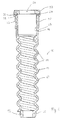
- the in Fig. 1 illustrated screw anchor 10 is made of plastic material and is divided into several sections. These are, for the first, a lower section 12 with a substantially cylindrical shape, a threaded section 14 and an upper section 16. In the region of the threaded section 14 are numerous threads 18, which are provided in the region of the external thread as a round thread. Inside the threaded portion 14 there is an internal thread 19, which may also be designed as a round thread, but may differ from the external thread 18 with respect to the thread pitch and thread pitch.
- the upper portion 16 is substantially cylindrical in shape and formed integrally with the threaded portion 14 as well as the lower portion 12.
- form-fitting elements may be provided in the form of extending in the longitudinal direction of the screw dowel ribs 20, which after casting around the screw with the concrete mass of a railway sleeper or slab track radial rotation of the screw dowel relative to prevent the surrounding concrete material.
- the in Fig. 1 illustrated screw anchor is provided with a sealing element 22 which extends from the upper end surface 24 of the upper portion 16 upwards. If the end face 24 is flush with the top of a railway sleeper, thus the sealing element 22 extends beyond the top of the threshold upwards.
- the sealing element 22 also narrows the opening 26 of the screw plug, so that after screwing in a sleeper screw, the sealing element 22 rests elastically on the sleeper screw.
- the extension of the sealing element 22 is from the sectional view of Fig. 1 which makes it clear that the sealing element 22 extends into the clear opening width of the upper section 16, so that the opening 26 has a smaller diameter than the cylindrical inner wall 28 of the upper section 16.
- the sealing element 22 has a dovetailed annular web 30 which engages positively in a dovetail-shaped annular groove 32 in an upper flange portion of the upper portion 16.
- the sealing element 22 is made of a material having high elasticity and thus also high deformation capacity, so that this can adapt to the outer contour of the screw when screwing the sleeper screw into the screw plug and can rest against it.
- the sealing element 22 extends beyond the top end face 24 and thus can not only prevent the ingress of moisture and dirt in the screw plug with inserted sleeper screw, but already serve as an overcurrent barrier for accumulated on the threshold top water.
- the sealing element 22 extends to the upper-side end surface 24 of the upper portion of the screw plug and has an opening 26, whose Cross-section corresponding to the outer wall of the upper section.
- the in Fig. 2 illustrated sealing element on the outer periphery of the upper portion adjacent fitting cylindrical skirt 38.
- the cylindrical skirt is made in one piece with the sealing element 22 and also made of a material with high elasticity.
- the advantage of the provided on the outer circumference cylindrical skirt 38 is that it can compensate for the inevitable occurring in a concrete sleeper contractions, and helps prevent radial stresses go out with any radial cracks from the dowel.
- the sealing element 22 bulges at radial pressure upwards and forms there as an overcurrent barrier for accumulated on top of the threshold or slab track water.
- the attachment of the in Fig. 2 illustrated sealing element can be done in different ways. On the one hand, a positive connection as in Fig. 1 be present between the upper portion of the dowel and the sealing element. Alternatively, it is also possible to attach the sealing element by the elastic, cylindrical skirt 38 is widened and attached to the upper portion of the screw plug where it produces a sufficiently viable frictional connection with the upper portion of the screw through its elasticity.
- Fig. 2 shown solution with a separate component attached sealing element or molded sealing element offers the possibility not only the To seal opening cross-section between the threshold screw and dowel, but to extend over the top of the concrete threshold and thus to provide an overcurrent barrier for water on the concrete sleeper.
- FIG. 3 illustrated embodiment combines features of in FIGS. 1 and 2 already explained embodiments. Similarities with respect to the embodiment according to Fig. 2 exist with respect to the provision of a cylindrical skirt 38, which is designed in one piece with the sealing element 22.
- the conformity to the embodiment according to Fig. 1 exists with respect to the opening cross-section 24, which is less than the cylindrical inner wall 28 of the upper portion 16.
- the sealing element extends over the end face 24 upwards and thus forms in the not yet compressed state of the sealing element and when installing the screw with the face 24 flush with the top of a railway sleeper or slab track already the desired overcurrent barrier to prevent or at least reduce the ingress of water or foreign particles in the dowel hole.
- FIGS. 1 . 2 and 3 the screw anchor 10 each have a substantially cylindrical outer shape.
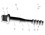
- the screw 50 has a screw head 52 with a square 54 and a cylindrical portion 56 with an external thread 58.
- the external thread 58 is in the portion 14 of the dowel in engagement with the internal thread 19 of the dowel, whereas in the conically widening portion 16 of the dowel 10, the screw thread 58 only slightly or not at all touches the inner wall of the dowel. In this way, the force engagement between the sleeper screw and the surrounding dowel is displaced into the lower dowel area 14 in order to reduce the near-surface stresses in the threshold area or in the region of the slab track.
- Fig. 4 illustrated embodiment provides the distance between the screw thread and dowels ago by the screw thread is substantially cylindrical, but the surrounding dowel is widened.
- the sleeper screw can be designed so that the thread is provided only in a certain area of the sleeper screw, whereby also the force engagement between the sleeper screw and dowels can be moved to the deeper dowel area.
- illustrated threshold screw is an example of this and has several sections.
- a first cylindrical portion 60 connects to the screw head 52 and has no external thread.
- the first section 60 merges via an intermediate section 62 into a second section 64, which is likewise cylindrical, but has thread elevations 66 of the external thread 58 in certain regions. Is the recording plug to the in Fig.
Landscapes
- Engineering & Computer Science (AREA)
- General Engineering & Computer Science (AREA)
- Mechanical Engineering (AREA)
- Architecture (AREA)
- Civil Engineering (AREA)
- Structural Engineering (AREA)
- Joining Of Building Structures In Genera (AREA)
- Connection Of Plates (AREA)
- Bridges Or Land Bridges (AREA)
- Machines For Laying And Maintaining Railways (AREA)
- Manufacturing Of Tubular Articles Or Embedded Moulded Articles (AREA)
- Gasket Seals (AREA)
Abstract
Description
- Die Erfindung betrifft einen Schraubdübel für das Einbetonieren in eine Eisenbahnschwelle oder Feste Fahrbahn und die kraftschlüssige Verbindung mit einer Schwellenschraube gemäß dem Oberbegriff des Anspruchs 1. Weiterhin betrifft die Erfindung eine Eisenbahnschwelle oder Feste Fahrbahn mit mindestens einem erfindungsgemäßen Schraubdübel und einer zugehörigen Schwellenschraube.
- Schraubdübel für das Einbetonieren in eine Eisenbahnschwelle dienen beim Eisenbahnbau zur Verbindung von Schiene und Schwelle. Dabei wird die Schienenbefestigung über Schwellenschrauben mit der Schwelle verbunden. Schraubdübel bestehen häufig aus Kunststoff und können bei der Herstellung einer Betonschwelle oder einer Festen Fahrbahn in diese eingegossen werden. Ein Grund für das Vorsehen eines Dübels aus Kunststoff besteht darin, dass eine elektrische Isolierung der Schwellenschraube gegenüber der Schwelle erfolgen soll.
- Der Nachteil einer Paarung aus Bauelementen unterschiedlicher Materialien, wie Schraubdübel aus Kunststoff und Eisenbahnschwellen aus Beton, besteht aber darin, dass diese unterschiedliche Wärmeausdehnungen besitzen, so dass es aufgrund der gegenüber Beton größeren Wärmeausdehnung des für Dübel üblicherweise verwendeten Kunststoffmaterials zum einen zur Bildung von Spalten zwischen Dübel und dem umgebenden Beton der Schwelle kommen kann, gleichzeitig aber auch bei höheren Temperaturen hohe Radialspannungen im Dübel und umgebenden Beton entstehen, die sogar zu Radialrissen im Beton führen können. Aufgrund der Toleranzlage zwischen Schraube und Dübel besteht in der Regel dort ein Luftspalt, in welchen Wasser, Sand und Schmutzpartikel eindringen können. Insbesondere beim Eindringen von Wasser wird der elektrische Widerstand des Befestigungssystems stark herabgesetzt und können die immer höher werdenden technischen Anforderungen der Signaltechnik nicht mehr erfüllt werden. Andererseits führt gefrorenes Wasser im Winter zu erhöhten Radialspannungen.
- Aus dem deutschen Gebrauchsmuster 87 06 556 ist ein Schraubdübel bekannt, in dessen Hohlraum in einer Ringnut ein Dichtring angeordnet ist. Der Dichtring liegt mit einer Dichtlippe am Außenumfang der eingeschraubten Schwellenschraube an und verhindert das Eindringen von Feuchtigkeit über die Ebene des Dichtrings hinaus.
- Der Erfindung liegt die Aufgabe zugrunde, einen Schraubdübel für das Einbetonieren in eine Eisenbahnschwelle sowie eine Eisenbahnschwelle oder Feste Fahrbahn mit mindestens einem derartigen Schraubdübel mit einer verbesserten Betriebssicherheit vorzuschlagen. Diese Aufgabe wird durch einen Schraubdübel mit den Merkmalen des Anspruchs 1 sowie eine Eisenbahnschwelle oder Feste Fahrbahn mit den Merkmalen des Anspruchs 9 gelöst. Bevorzugte Ausführungsformen der Erfindung folgen aus den übrigen Ansprüchen.
- Erfindungsgemäß umfasst ein Schraubdübel für das Einbetonieren in eine Eisenbahnschwelle oder Feste Fahrbahn und die kraftschlüssige Verbindung mit einer Schwellenschraube einen Gewindeabschnitt mit außen am Schraubdübel angeordneten Außengewindegängen sowie innen im Schraubdübel angeordneten Innengewindegängen. Weiterhin umfasst der Schraubdübel einen im Einbauzustand nahe der Dübelöffnung gelegenen oberen Teilabschnitt ohne Außengewinde. Der Schraubdübel ist dadurch gekennzeichnet, dass im oberen Teilabschnitt ein Werkstoff mit hoher Elastizität angeordnet ist, der sich im Einbauzustand unter Bildung einer nach oben herauskragenden wulstartigen Erhebung über die Ebene der Dübelöffnung hinaus nach oben erstreckt sowie den freien Öffnungsquerschnitt des Innenraums des oberen Teilabschnitts verringert.
- Der Werkstoff mit hoher Elastizität ist somit nicht nur in dem Inneren der Dübelöffnung angeordnet, um einen toleranzbedingten Spalt zwischen Schwellenschraube und Dübel abzudichten, sondern erstreckt sich nach oben über die Ebene der Dübelöffnung hinaus, wodurch bei bündig mit der Oberseite der Schwelle abschließendem oberen Teilabschnitt des Dübels der Wertstoff mit hoher Elastizität sich über die Oberseite der Schwelle hinaus nach oben erstreckt. Auf diese Weise wird eine Barriere geschaffen, welche verhindert, dass auf der Oberseite der Schwelle befindliches Wasser in die Dübelöffnung hineinfließen kann. Im Unterschied zu
DE-U-87 06 556 , bei der sich der Dichtring erst unterhalb der Dübelöffnung im Dübelhohlraum befindet, wird somit auf sehr wirksame Weise die Benetzung der Schwellenschraube mit Wasser verhindert. - Nach einer bevorzugten Ausführungsform der Erfindung ist der Werkstoff mit hoher Elastizität ein separates Bauteil, das an dem oberen Teilabschnitt befestigt ist. Es kann sich somit bei dem Werkstoff mit hoher Elastizität um einen Dichtring handeln, der in einer geeigneten Weise mit dem oberen Teilabschnitt verbunden ist, wie beispielsweise mit diesem verklebt oder verschweißt ist. Bevorzugt ist es allerdings, dass das separate Bauteil einen schwalbenschwanzförmigen Ansatz aufweist, der formschlüssig in eine Ringnut am oberen Teilabschnitt eingreift. Auf diese Weise kann der Schraubdübel bereits als eine vormontierte Baueinheit vorkonfektioniert werden und ein weiterer Herstellschritt für das Erzeugen einer kraftschlüssigen Verbindung zwischen dem separaten Bauteil mit hoher Elastizität und dem oberen Teilabschnitt entfallen. Aufgrund der hohen Elastizität des separaten Bauteils kann auch im Falle einer Ringnut ein schwalbenschwanzförmiger Ansatz gewählt werden, da das Material ausreichend komprimierbar ist, um in eine derartige Nut eingesteckt zu werden, sich darin wieder aufzuweiten und in der Nut formschlüssig gehalten zu werden.
- Nach einer alternativen Ausführungsform ist das separate Bauteil auf dem oberen Teilabschnitt aufgesteckt. Bei dieser Ausgestaltung kann der als separates Bauteil vorgesehene Werkstoff mit hoher Elastizität aufgeweitet und als Hülse auf den oberen Teilabschnitt aufgesteckt werden und hält reibschlüssig durch seine eigene Elastizität, die eine Rückstellkraft in radialer Richtung erzeugt.
- Nach einer alternativen bevorzugten Ausführungsform ist der Werkstoff mit hoher Elastizität an dem oberen Teilabschnitt angespritzt. Auf diese Weise lässt sich der Montageaufwand weiter reduzieren, jedoch sind höhere Investitionsaufwendungen für ein Zwei-Komponenten-Spritzgießverfahren erforderlich, was allerdings bei Massenprodukten wie Schraubdübeln mit verringertem Vormontageaufwand gerechtfertigt ist.
- Vorzugsweise ist das Außengewinde ein Rundgewinde, was sich in Bezug auf den Kraftschluss bei Radialspannungen zwischen Dübel und Betonmaterial als sehr günstig erwiesen hat.
- Nach einer bevorzugten Ausführungsform umfasst der Schraubdübel weiterhin mindestens ein in Längsrichtung außen an dem Schraubdübel vorgesehenes Formschlusselement, vorzugsweise in Form mehrerer Stege. Derartige Formschlusselemente dienen dazu, ein unerwünschtes Verdrehen des Schraubdübels relativ zur Betonschwelle zu verhindern und tragen zur Funktionssicherheit des erfindungsgemäßen Scbraubdübels bei.
- Vorzugsweise ist der Werkstoff mit hoher Elastizität zusätzlich zumindest bereichsweise am Außenumfang des oberen Teilabschnitts als nachgiebige Ummantelung angeordnet. Diese Maßnahme besitzt den Vorteil, dass Rissbildung um den oberen Teilabschnitt des Schraubdübels verringert werden kann. Zum einen treten durch Wärmeausdehnungen Spannungen auf, die zur Rissbildung im Beton führen können, zum anderen aber können Risse auch durch die Überbeanspruchung des Randbereichs infolge der von der Schiene über die Schwellenschraube in den Dübel eingeleiteten Horizontalkräfte auftreten.
- Die erfindungsgemäße Eisenbahnschwelle oder Feste Fahrbahn mit mindestens einem Schraubdübel nach der Erfindung ist so gestaltet, dass der Krafteingriff zwischen Schwellenschraube und Dübel in den tieferen Dübelbereich verlagert wird und entsprechend auch in den tieferen Bereich der Schwelle oder Festen Fahrbahn. Auf diese Weise lässt sich die Spannung reduzieren. Nach einer ersten Alternative umfasst die Eisenbahnschwelle oder Feste Fahrbahn dazu eine Schwellenschraube, die einen zylinderförmigen Abschnitt besitzt, der ein Außengewinde aufweist, wobei der Schraubdübel einen sich zur Einstecköffnung hin aufweitenden kegelförmigen Bereich aufweist. Auf diese Weise wird der Eingriff zwischen dem Gewinde der Schwellenschraube und dem Schraubd3äbel in den unteren Bereich des Dübels verlagert, d.h. in den tieferen Dübelbereich, der weiter von der Einstecköffnung entfernt liegt. Alternativ ist es auch möglich, die Schwellenschraube so zu gestalten, dass diese einen ersten und einen zweiten zylindrischen Abschnitt aufweist. Der erste zylindrische Abschnitt hat einen größeren Kerndurchmesser als der zweite zylindrische Abschnitt und liegt näher zum Schraubenkopf als der zweite zylindrische Abschnitt. Indem nur der zweite zylindrische Abschnitt zumindest bereichsweise ein Außengewinde aufweist wird ebenfalls der Krafteingriff zwischen Schwellenschraube und Schraubdübel in den tieferen Dübelbereich und damit in den tieferen Bereich der Schwelle oder Festen Fahrbahn verlagert. Unter dem Kerndurchmesser wird dabei derjenige Durchmesser verstanden, der durch die tiefsten Gewindenuten definiert wird.
- Eine dritte Möglichkeit besteht darin, den Krafteingriff durch die Gestaltung des Dübelgewindes, z.B. durch das Vorsehen unterschiedlicher Dübelgewinde im oberen und im unteren Dübelbereich dahingehen zu beeinflussen, dass der Krafteingriff in den tieferen Dübelbereich verlagert wird.
- Nachfolgend wird die Erfindung rein beispielhaft anhand der beiliegenden Figuren beschrieben, in denen
- Figur 1
- eine erste Ausführungsform eines erfindungsgemäßen Schraubdübels zeigt;
- Figur 2
- eine zweite Ausführungsform eines erfindungsgemäßen Schraubdübels zeigt;
- Figur 3
- eine dritte Ausführungsform eines erfindungsgemäßen Schraubdübels zeigt;
- Figur 4
- einen erfindungsgemäßen Schraubdübel mit eingedrehter Schwellenschraube darstellt; und
- Figur 5
- eine alternative Gestaltung einer Schwellenschraube zur Verwendung mit einem erfindungsgemäßen Schraubdübel zeigt.
- Der in
Fig. 1 dargestellte Schraubdübel 10 besteht aus Kunststoffmaterial und gliedert sich in mehrere Abschnitte. Diese sind zum ersten ein unterer Teilabschnitt 12 mit im Wesentlichen zylindrischer Form, ein Gewindeabschnitt 14 sowie ein oberer Teilabschnitt 16. Im Bereich des Gewindeabschnitts 14 befinden sich zahlreiche Gewindegänge 18, die im Bereich des Außengewindes als Rundgewinde vorgesehen sind. Im Inneren des Gewindeabschnitts 14 besteht ein Innengewinde 19, das ebenfalls als Rundgewinde ausgeführt sein kann, sich jedoch in Bezug auf die Gewindesteigung sowie Gewindeteilung von dem Außengewinde 18 unterscheiden kann. - Der obere Teilabschnitt 16 ist im Wesentlichen zylinderförmig ausgeführt und einstückig mit dem Gewindeabschnitt 14 wie auch dem unteren Teilabschnitt 12 ausgebildet. Am Außenumfang des unteren Teilabschnitts 12 und/oder am Außenumfang des oberen Teilabschnitts 16 können Formschlusselemente in Form von in Längsrichtung des Schraubdübels verlaufenden Rippen 20 vorgesehen sein, welche nach dem Umgießen des Schraubdübels mit der Betonmasse einer Eisenbahnschwelle oder Festen Fahrbahn ein radiales Verdrehen des Schraubdübels relativ zu dem umgebenden Betonmaterial verhindern.
- Der in
Fig. 1 dargestellte Schraubdübel ist mit einem Dichtelement 22 versehen, das sich von der oberen Stirnfläche 24 des oberen Teilabschnitts 16 nach oben erstreckt. Wenn die Stirnfläche 24 bündig mit der Oberseite einer Eisenbahnschwelle abschließt, erstreckt sich somit das Dichtelement 22 über die Oberseite der Schwelle hinaus nach oben. - Das Dichtelement 22 verengt zudem die Öffnung 26 des Schraubdübels, so dass nach dem Eindrehen einer Schwellenschraube das Dichtelement 22 elastisch an der Schwellenschraube anliegt.
- Die Erstreckung des Dichtelements 22 ist aus der Schnittansicht der
Fig. 1 ersichtlich, die deutlich macht, dass sich das Dichtelement 22 in die lichte Öffnungsweite des oberen Teilabschnitts 16 hineinerstreckt, so dass die Öffnung 26 einen geringeren Durchmesser aufweist als die zylindrische Innenwand 28 des oberen Teilabschnitts 16. - Aus
Fig. 1 ist zusätzlich ersichtlich, dass das Dichtelement 22 einen schwalbenschwanzförmigen Ringsteg 30 aufweist, der in eine schwalbenschwanzförmige Ringnut 32 in einem oberen Flanschabschnitt des oberen Teilabschnitts 16 formschlüssig eingreift. - Das Dichtelement 22 ist aus einem Werkstoff mit hoher Elastizität und somit auch hohem Verformungsvermögen hergestellt, so dass dieses beim Eindrehen der Schwellenschraube in den Schraubdübel sich der Außenkontur der Schraube anpassen und an diese anlegen kann. Darüber hinaus erstreckt sich das Dichtelement 22 über die oberseitige Stirnfläche 24 hinaus und kann somit nicht nur das Eindringen von Feuchtigkeit und Schmutz in den Schraubdübel mit eingesetzter Schwellenschraube unterbinden, sondern bereits als eine Überstrombarriere für auf der Schwellenoberseite angesammeltes Wasser dienen.
- Die in
Fig. 2 dargestellte Ausführungsform entspricht im Wesentlichen derjenigen nachFigur 1 , unterscheidet sich jedoch durch die Gestaltung des Dichtelements 22. Hier erstreckt sich das Dichtelement bis zur oberseitigen Abschlussfläche 24 des oberen Teilabschnitts des Schraubdübels und weist eine Öffnung 26 auf, deren Querschnitt dem der Außenwand des oberen Teilabschnitts entspricht. Zusätzlich weist aber das inFig. 2 dargestellte Dichtelement eine am Außenumfang des oberen Teilabschnitts anliegende, zylindrische Schürze 38 auf. Die zylindrische Schürze ist dabei einstückig mit dem Dichtelement 22 ausgeführt und ebenfalls aus einem Material mit hoher Elastizität hergestellt. Der Vorteil der am Außenumfang vorgesehenen zylindrischen Schürze 38 besteht darin, dass diese die in einer Betonschwelle unweigerlich auftretenden Kontraktionen kompensieren kann, und verhindern hilft, dass Radialspannungen mit eventuellen Radialrissen vom Dübel ausgehen. Darüber hinaus wölbt sich das Dichtelement 22 bei radialem Druck nach oben und bildet da eine Überstrombarriere für auf der Oberseite der Schwelle oder Festen Fahrbahn angesammeltes Wasser. - Die Befestigung des in
Fig. 2 dargestellten Dichtelements kann auf unterschiedliche Weise erfolgen. Zum einen kann eine formschlüssige Verbindung wie inFig. 1 dargestellt zwischen dem oberen Teilabschnitt des Dübels und dem Dichtelement vorhanden sein. Alternativ ist es auch möglich, das Dichtelement zu befestigen, indem die elastische, zylindrische Schürze 38 aufgeweitet und auf den oberen Teilabschnitt des Schraubdübels aufgesteckt wird, wo diese durch ihre Elastizität eine ausreichend tragfähige reibschlüssige Verbindung mit dem oberen Teilabschnitt des Schraubdübels herstellt. - Alternativ ist es sowohl bei der in
Fig. 2 wie auch der inFigur 1 dargestellten Ausführungsform möglich, das Dichtelement 22 bei der Herstellung des Schraubdübels anzuspritzen, wozu eine bekannte 2K-Spritzgießtechnologie zur Anwendung gelangt. - Auch die in
Fig. 2 dargestellte Lösung mit als separates Bauteil befestigtem Dichtelement oder angespritztem Dichtelement bietet die Möglichkeit, nicht nur den Öffnungsquerschnitt zwischen Schwellenschraube und Dübel abzudichten, sondern sich über die Oberseite der Betonschwelle zu erstrecken und damit eine Überstrombarriere für Wasser auf der Betonschwelle zu bieten. - Die in
Fig. 3 dargestellte Ausführungsform kombiniert Merkmale der inFiguren 1 und2 bereits erläuterten Ausführungsformen. Ähnlichkeiten in Bezug auf die Ausführungsform nachFig. 2 bestehen in Bezug auf das Vorsehen einer zylindrischen Schürze 38, die einstückig mit dem Dichtelement 22 ausgestaltet ist. Die Übereinstimmung zur Ausführungsform nachFig. 1 besteht in Bezug auf den Öffnungsquerschnitt 24, der geringer ist als die zylindrische Innenwand 28 des oberen Teilabschnitts 16. Darüber hinaus erstreckt sich das Dichtelement über die Stirnfläche 24 nach oben und bildet somit auch im noch nicht komprimierten Zustand des Dichtelements und bei Einbau des Schraubdübels mit der Stirnfläche 24 bündig mit der Oberseite einer Eisenbahnschwelle oder Festen Fahrbahn bereits die gewünschte Überstrombarriere, die das Eindringen von Wasser oder Fremdpartikeln in die Dübelöffnung verhindern oder zumindest reduzieren soll. - Bei den oben beschriebenen Ausführungsformen nach
Figuren 1 ,2 und3 weist der Schraubdübel 10 jeweils eine im Wesentlichen zylinderförmige Außenform auf. Hiervon unterscheidet sich die Ausführungsform nachFig. 4 , bei welcher der Abschnitt 16 des Schraubdübels keine zylindrische Form besitzt, sondern konisch zur Öffnung 26 hin aufgeweitet ist. Das inFig. 4 dargestellte Dichtelement 22 entspricht im Wesentlichen dem nachFig. 3 , wobei ersichtlich ist, dass sich durch die elastische Verformung der Öffnung 26 im Bereich des Schraubenschafts ein Wulst 40 bildet, der ringförmig den Schraubenschaft umgibt und sich nach oben erstreckt. - Die Schraube 50 weist einen Schraubenkopf 52 mit einem Vierkant 54 sowie einen zylinderförmigen Abschnitt 56 mit einem Außengewinde 58 auf. Das Außengewinde 58 ist im Abschnitt 14 des Dübels in Eingriff mit dem Innengewinde 19 des Dübels, wohingegen in dem sich konisch aufweitenden Abschnitt 16 des Dübels 10 das Schraubengewinde 58 nur noch geringfügig oder aber überhaupt nicht mehr die Innenwandung des Dübels berührt. Auf diese Weise wird der Krafteingriff zwischen Schwellenschraube und dem umgebenden Dübel in den tieferen Dübelbereich 14 verlagert, um die oberflächennahen Spannungen im Schwellenbereich oder im Bereich der Festen Fahrbahn zu reduzieren.
- Die in
Fig. 4 dargestellte Ausführungsform stellt den Abstand zwischen Schraubengewinde und Dübel her, indem das Schraubengewinde im Wesentlichen zylinderförmig ist, der umgebende Dübel aber aufgeweitet ist. - Alternativ hierzu kann aber auch die Schwellenschraube so gestaltet werden, dass das Gewinde nur in einem bestimmten Bereich der Schwellenschraube vorgesehen ist, wodurch ebenfalls der Krafteingriff zwischen Schwellenschraube und Dübel in den tieferen Dübelbereich verlagert werden kann. Die in
Fig. 5 dargestellte Schwellenschraube stellt ein Beispiel hierfür dar und weist mehrere Abschnitte auf. Ein erster zylinderförmiger Abschnitt 60 schließt sich an den Schraubenkopf 52 an und weist kein Außengewinde auf. Der erste Abschnitt 60 geht über einen Zwischenabschnitt 62 in einen zweiten Abschnitt 64 über, der ebenfalls zylinderförmig ist, aber bereichsweise Gewindeerhebungen 66 des Außengewindes 58 aufweist. Ist der Aufnahmedübel zu der inFig. 5 dargestellten Schwellenschraube 50 entsprechend geformt, so wird deutlich, dass die Gewindegänge 66 nur im unteren Bereich des Dübels in ein entsprechendes Innengewinde des Dübels eingreifen, während der erste Abschnitt 60 an einer glatten, d.h. nicht mit einem Innengewinde versehenen Wand des Dübels anliegt. Auch diese Maßnahme dient dazu, den Krafteingriff in den tieferen Bereich des Dübels und damit der umgebenden Schwelle oder Festen Fahrbahn zu verlagern. Allen Ausführungsformen ist gemeinsam, dass durch die Gestaltung des Dübels eine Abdichtung nach oben und innen erfolgt, wodurch sich der elektrische Widerstand des Schienenbefestigangssystems erhöht. Darüber hinaus wird beim Vorsehen einer elastischen Schürze der äußere Dübelschaft umgriffen, wodurch sich eine Spannungsreduzierung in der Betonschwelle im Dübelbereich erzielen lässt. Eine weitere Spannungsreduzierung in der Betonschwelle oder Festen Fahrbahn im Dübelbereich kann durch die anhand der an zwei Beispielen erläuterten Verlagerung des Krafteingriffs zwischen Schwellenschraube und Dübel in einen oberflächenferneren Bereich erzielen.
Claims (11)
- Schraubdübel für das Einbetonieren in eine Eisenbahnschwelle oder Feste Fahrbahn und die kraftschlüssige Verbindung mit einer Schwellenschraube, umfassend:- einen Gewindeabschnitt (14) mit außen am Schraubdübel (10) angeordneten Außengewindegängen (18) sowie innen im Schraubdübel angeordneten Innengewindegängen (19); und- einen im Einbauzustand nahe der Dübelöffnung (26) gelegenen oberen Teilabschnitt (16) ohne Außengewinde;dadurch gekennzeichnet, dass- im oberen Teilabschnitt (16) ein Werkstoff mit hoher Elastizität angeordnet ist, der im Einbauzustand eine sich über die oberseitige Abschlussfläche (36) des oberen Teilabschnitts (16) hinaus nach oben erstreckende herauskragende Erhebung bildet sowie den freien Öffnungsquerschnitt des Innenraums des oberen Teilabschnitts (16) verringert.
- Schraubdübel nach Anspruch 1,
dadurch gekennzeichnet, dass der Werkstoff mit hoher Elastizität ein separates Bauteil (22) ist, das an dem oberen Teilabschnitt (16) befestigt ist. - Schraubdübel nach Anspruch 2,
dadurch gekennzeichnet, dass das separate Bauteil (22) einen schwalbenschwanzförmigen Ansatz (30) aufweist, der formschlüssig in eine Ringnut (32) am oberen Teilabschnitt (16) eingreift. - Schraubdübels nach Anspruch 2,
dadurch gekennzeichnet, dass das separate Bauteil (22) auf den oberen Teilabschnitt (16) aufgesteckt ist. - Schraubdübel nach Anspruch 1,
dadurch gekennzeichnet, dass der Werkstoff mit hoher Elastizität an dem oberen Teilabschnitt (16) angespritzt ist. - Schraubdübel nach einem der vorhergehenden Ansprüche,
dadurch gekennzeichnet, dass das Außengewinde (18) ein Rundgewinde ist. - Schraubdübel nach einem der vorhergehenden Ansprüche, weiterhin umfassend mindestens ein im Wesentlichen in Längsrichtung außen an dem Schraubdübel vorgesehenes Formschlusselement (20), vorzugsweise in Form mehrerer Stege.
- Schraubdübel nach einem der vorhergehenden Ansprüche, dadurch gekennzeichnet, dass der Werkstoff mit hoher Elastizität zusätzlich zumindest bereichsweise am Außenumfang des oberen Teilabschnitts als nachgiebige Ummantelung (38) angeordnet ist.
- Eisenbahnschwelle oder Feste Fahrbahn mit mindestens einem Schraubdübel nach einem der vorhergehenden Ansprüche.
- Eisenbahnschwelle oder Feste Fahrbahn nach Anspruch 9, weiter umfassend eine Schwellenschraube, die einen zylinderförmigen Abschnitt besitzt, der ein Außengewinde aufweist; wobei
der Schraubdübel einen sich zur Einstecköffnung hin aufweitenden kegelförmigen Bereich aufweist. - Eisenbahnschwelle oder Feste Fahrbahn nach Anspruch 9, weiter umfassend eine Schwellenschraube, die einen ersten zylindrischen Abschnitt und einen zweiten zylindrischen Abschnitt aufweist, wobei- der ersten zylindrische Abschnitt näher zum Schraubenkopf angeordnet ist als der zweite zylindrische Abschnitt und einen größeren Kerndurchmesser aufweist als der zweite zylindrische Abschnitt; und- nur der zweite zylindrische Abschnitt zumindest bereichsweise ein Außengewinde aufweist.
Priority Applications (7)
| Application Number | Priority Date | Filing Date | Title |
|---|---|---|---|
| EP09178497.5A EP2333154B1 (de) | 2009-12-09 | 2009-12-09 | Schraubdübel für Schienenbefestigungen |
| ES09178497T ES2571941T3 (es) | 2009-12-09 | 2009-12-09 | Taco roscado para fijaciones de carril |
| US13/515,027 US8840036B2 (en) | 2009-12-09 | 2010-12-08 | Screw anchor for rail attachments |
| PCT/EP2010/069160 WO2011070060A1 (de) | 2009-12-09 | 2010-12-08 | Schraubdübel für schienenbefestigungen |
| EP10794940A EP2510153A1 (de) | 2009-12-09 | 2010-12-08 | Schraubdübel für schienenbefestigungen |
| EA201290478A EA023292B1 (ru) | 2009-12-09 | 2010-12-08 | Винтовой дюбель для крепления рельса |
| CN201080055914.8A CN102713065B (zh) | 2009-12-09 | 2010-12-08 | 用于轨道固定件的螺旋榫 |
Applications Claiming Priority (1)
| Application Number | Priority Date | Filing Date | Title |
|---|---|---|---|
| EP09178497.5A EP2333154B1 (de) | 2009-12-09 | 2009-12-09 | Schraubdübel für Schienenbefestigungen |
Publications (2)
| Publication Number | Publication Date |
|---|---|
| EP2333154A1 true EP2333154A1 (de) | 2011-06-15 |
| EP2333154B1 EP2333154B1 (de) | 2016-02-24 |
Family
ID=42045457
Family Applications (2)
| Application Number | Title | Priority Date | Filing Date |
|---|---|---|---|
| EP09178497.5A Active EP2333154B1 (de) | 2009-12-09 | 2009-12-09 | Schraubdübel für Schienenbefestigungen |
| EP10794940A Withdrawn EP2510153A1 (de) | 2009-12-09 | 2010-12-08 | Schraubdübel für schienenbefestigungen |
Family Applications After (1)
| Application Number | Title | Priority Date | Filing Date |
|---|---|---|---|
| EP10794940A Withdrawn EP2510153A1 (de) | 2009-12-09 | 2010-12-08 | Schraubdübel für schienenbefestigungen |
Country Status (6)
| Country | Link |
|---|---|
| US (1) | US8840036B2 (de) |
| EP (2) | EP2333154B1 (de) |
| CN (1) | CN102713065B (de) |
| EA (1) | EA023292B1 (de) |
| ES (1) | ES2571941T3 (de) |
| WO (1) | WO2011070060A1 (de) |
Cited By (1)
| Publication number | Priority date | Publication date | Assignee | Title |
|---|---|---|---|---|
| EP3667105A1 (de) * | 2018-12-12 | 2020-06-17 | Adolf Würth GmbH & Co. KG | Kunststoffspreizdübel, verfahren zum befestigen einer schraube und eines kunststoffspreizdübels und anordnung mit einem kunststoffspreizdübel |
Families Citing this family (16)
| Publication number | Priority date | Publication date | Assignee | Title |
|---|---|---|---|---|
| CN103038421B (zh) * | 2010-05-26 | 2015-01-14 | 施维哈克股份公司 | 用于将轨道固定在枕木上的塑料螺旋销 |
| PL2431520T3 (pl) * | 2010-09-21 | 2015-11-30 | Vossloh Werke Gmbh | Kotwa śrubowa do zamocowania szyn |
| DE102011055797A1 (de) | 2011-11-29 | 2013-05-29 | Track Tec GmbH | Befestigungsvorrichtung mit Dübel und Bewehrung |
| DE102012107732A1 (de) * | 2012-08-22 | 2014-05-15 | Vossloh-Werke Gmbh | Kunststoffdübel für die Befestigung einer Schiene und Kombination aus einem solchen Kunststoffdübel und einer Schwellenschraube |
| DE102013110288A1 (de) * | 2013-09-18 | 2015-03-19 | Vossloh-Werke Gmbh | Plattenelement für einen Befestigungspunkt, in dem eine für Schienenfahrzeuge vorgesehene Schiene befestigt ist, und Befestigungspunkt |
| US9464653B2 (en) | 2014-03-28 | 2016-10-11 | Thanomsak Hongthong | Concrete wall anchor |
| CN104313958A (zh) * | 2014-08-25 | 2015-01-28 | 武汉闻歇纳科技有限公司 | 一种道岔立螺栓的取套工艺 |
| FR3031146B1 (fr) * | 2014-12-24 | 2017-01-13 | Airbus Defence & Space Sas | Dispositif de fixation amortissant entre deux elements a assembler, procede de fabrication d'un tel dispositif, ensemble de deux elements assembles a l'aide d'un tel dispositif, et procede d'assemblage |
| US10531052B2 (en) | 2017-01-27 | 2020-01-07 | Live Earth Imaging Enterprises, L.L.C. | Real-time satellite imaging system |
| RU2682440C2 (ru) * | 2017-04-24 | 2019-03-19 | Игорь Викторович Прохоров | Устройство для крепления теплоизоляции |
| RU177455U1 (ru) * | 2017-06-01 | 2018-02-21 | Акционерное Общество "Комплексное Сервисное Обслуживание Пути" | Дюбель крепежного узла рельсового скрепления |
| RU186869U1 (ru) * | 2018-09-11 | 2019-02-06 | Антон Владимирович Кривошеев | Дюбель путевой |
| RU202756U1 (ru) * | 2020-10-01 | 2021-03-04 | Открытое Акционерное Общество "Российские Железные Дороги" | Дюбель крепежного узла промежуточного рельсового скрепления |
| US20220154755A1 (en) * | 2020-11-13 | 2022-05-19 | Owens Corning Intellectual Capital, Llc | Acoustically attenuating fasteners |
| US20250116333A1 (en) * | 2023-10-04 | 2025-04-10 | Jamak Fabrication-Tex Llc | Rail fastener sealing systems and methods for sealing a rail fastening assembly |
| ES3054094A1 (es) | 2024-07-11 | 2026-01-29 | Hispanica De Componentes S L | Vaina para la fijacion de carriles ferroviarios |
Citations (3)
| Publication number | Priority date | Publication date | Assignee | Title |
|---|---|---|---|---|
| FR2105593A5 (de) * | 1970-09-14 | 1972-04-28 | Laeri Max | |
| DE8706556U1 (de) | 1987-05-07 | 1987-08-13 | Wirthwein, Udo, 6993 Creglingen | Schraubdübel |
| DE19845696A1 (de) | 1998-10-05 | 2000-04-06 | Grohe Kg Hans | Dübel mit Abdichtung |
Family Cites Families (7)
| Publication number | Priority date | Publication date | Assignee | Title |
|---|---|---|---|---|
| US1248007A (en) * | 1916-09-20 | 1917-11-27 | Henry B Newhall | Bolt-anchor. |
| DE4413743A1 (de) * | 1994-04-20 | 1995-10-26 | Hilti Ag | Befestigungsanker |
| CN2421312Y (zh) * | 1999-11-29 | 2001-02-28 | 铁道部鞍山工务器材厂 | 一种混凝土轨枕的预埋塑料套管及螺纹道钉 |
| DE10014688A1 (de) * | 2000-03-24 | 2001-09-27 | Emhart Inc | Halteelement zur Befestigung von Bauteilen an einem mit einem Durchbruch versehenen Träger |
| CN2661748Y (zh) * | 2003-01-23 | 2004-12-08 | 株洲时代新材料科技股份有限公司 | 混凝土轨枕用塑料套管 |
| JP4911275B2 (ja) * | 2005-06-24 | 2012-04-04 | Nok株式会社 | 密封構造 |
| CN201024359Y (zh) * | 2007-03-27 | 2008-02-20 | 铁道科学研究院通信信号研究所 | 钢螺纹尼龙螺旋套管 |
-
2009
- 2009-12-09 EP EP09178497.5A patent/EP2333154B1/de active Active
- 2009-12-09 ES ES09178497T patent/ES2571941T3/es active Active
-
2010
- 2010-12-08 US US13/515,027 patent/US8840036B2/en not_active Expired - Fee Related
- 2010-12-08 EP EP10794940A patent/EP2510153A1/de not_active Withdrawn
- 2010-12-08 WO PCT/EP2010/069160 patent/WO2011070060A1/de not_active Ceased
- 2010-12-08 CN CN201080055914.8A patent/CN102713065B/zh not_active Expired - Fee Related
- 2010-12-08 EA EA201290478A patent/EA023292B1/ru not_active IP Right Cessation
Patent Citations (3)
| Publication number | Priority date | Publication date | Assignee | Title |
|---|---|---|---|---|
| FR2105593A5 (de) * | 1970-09-14 | 1972-04-28 | Laeri Max | |
| DE8706556U1 (de) | 1987-05-07 | 1987-08-13 | Wirthwein, Udo, 6993 Creglingen | Schraubdübel |
| DE19845696A1 (de) | 1998-10-05 | 2000-04-06 | Grohe Kg Hans | Dübel mit Abdichtung |
Cited By (1)
| Publication number | Priority date | Publication date | Assignee | Title |
|---|---|---|---|---|
| EP3667105A1 (de) * | 2018-12-12 | 2020-06-17 | Adolf Würth GmbH & Co. KG | Kunststoffspreizdübel, verfahren zum befestigen einer schraube und eines kunststoffspreizdübels und anordnung mit einem kunststoffspreizdübel |
Also Published As
| Publication number | Publication date |
|---|---|
| CN102713065B (zh) | 2015-07-08 |
| EP2333154B1 (de) | 2016-02-24 |
| EA201290478A1 (ru) | 2012-11-30 |
| EA023292B1 (ru) | 2016-05-31 |
| US8840036B2 (en) | 2014-09-23 |
| US20120298765A1 (en) | 2012-11-29 |
| WO2011070060A1 (de) | 2011-06-16 |
| ES2571941T3 (es) | 2016-05-27 |
| CN102713065A (zh) | 2012-10-03 |
| EP2510153A1 (de) | 2012-10-17 |
Similar Documents
| Publication | Publication Date | Title |
|---|---|---|
| EP2333154B1 (de) | Schraubdübel für Schienenbefestigungen | |
| EP2196580B1 (de) | Schraubdübel mit konischer Form für Schienenbefestigungen | |
| EP2596172B1 (de) | Schienenbefestigungssystem | |
| EP2888407B1 (de) | Kunststoffdübel für die befestigung einer schiene | |
| DE102012101320A1 (de) | Schraube und damit hergestellte Dünnblechverbindung | |
| DE102010024870A1 (de) | Vorrichtung zum Befestigen eines Bauteils an einem Befestigungsbolzen | |
| EP2431520B1 (de) | Schraubdübel für Schienenbefestigung | |
| WO2013079210A2 (de) | Befestigungsvorrichtung mit dübel und bewehrung | |
| EP1899613B1 (de) | Schraubanker | |
| EP3042090A1 (de) | Verbindungseinsatz sowie ein einbettverfahren und ein herstellungsverfahren dafür | |
| EP2108545B1 (de) | Anordnung zur Befestigung eines Profils, insbesondere eines Hohlprofils, an einem Fahrzeugdach | |
| DE202013103906U1 (de) | Schwellenschraube für die Befestigung einer Schiene und Kombination aus einer solchen Schwellenschraube und einem Kunststoffdübel | |
| DE102011102825B4 (de) | Verbindungsanordnung und Verfahren zur Herstellung einer Durchstanzsicherung | |
| DE102013004392A1 (de) | Tülle und Befestigungselement zum Befestigen einer Materialschicht | |
| DE10311471A1 (de) | Gewindeformende Schraube für Untergründe aus harten Vollbaustoffen | |
| DE102013224459A1 (de) | Verbindungseinrichtung umfassend eine Abstandsbuchse und eine Schraube | |
| EP1394420A2 (de) | Einsatzteil für eine Wandöffnung, insbesondere an einer Fahrzeugkarosserie | |
| WO2014048989A1 (de) | Montageschraube zur befestigung von beschlagteilen an hohlkammerprofilen, bausatz einer montageschraube und anordnung eines mehrkammerprofils und einer montagschraube | |
| EP2895751B1 (de) | Schraube und ihre verwendung | |
| DE102009006207A1 (de) | Befestigungsanordnung und Befestigungselement | |
| DE102021127665A1 (de) | Abstandhaltesystem und Befestigungsanordnung | |
| DE102008057903A1 (de) | Nietteil mit geschlitztem Schaft | |
| DE3416784A1 (de) | Tuerblatt mit richtvorrichtung | |
| DE19652898B4 (de) | Ankerhülse | |
| EP2466008B1 (de) | Vorrichtung zur Verankerung eines zweiten Betonbauteils an einem ersten Betonbauteil, insbesondere einer Kappe am Überbau eines Brückentragwerks |
Legal Events
| Date | Code | Title | Description |
|---|---|---|---|
| PUAI | Public reference made under article 153(3) epc to a published international application that has entered the european phase |
Free format text: ORIGINAL CODE: 0009012 |
|
| 17P | Request for examination filed |
Effective date: 20100628 |
|
| AK | Designated contracting states |
Kind code of ref document: A1 Designated state(s): AT BE BG CH CY CZ DE DK EE ES FI FR GB GR HR HU IE IS IT LI LT LU LV MC MK MT NL NO PL PT RO SE SI SK SM TR |
|
| 17Q | First examination report despatched |
Effective date: 20121205 |
|
| GRAP | Despatch of communication of intention to grant a patent |
Free format text: ORIGINAL CODE: EPIDOSNIGR1 |
|
| INTG | Intention to grant announced |
Effective date: 20150715 |
|
| GRAS | Grant fee paid |
Free format text: ORIGINAL CODE: EPIDOSNIGR3 |
|
| GRAA | (expected) grant |
Free format text: ORIGINAL CODE: 0009210 |
|
| AK | Designated contracting states |
Kind code of ref document: B1 Designated state(s): AT BE BG CH CY CZ DE DK EE ES FI FR GB GR HR HU IE IS IT LI LT LU LV MC MK MT NL NO PL PT RO SE SI SK SM TR |
|
| REG | Reference to a national code |
Ref country code: GB Ref legal event code: FG4D Free format text: NOT ENGLISH |
|
| REG | Reference to a national code |
Ref country code: CH Ref legal event code: EP |
|
| REG | Reference to a national code |
Ref country code: AT Ref legal event code: REF Ref document number: 776815 Country of ref document: AT Kind code of ref document: T Effective date: 20160315 |
|
| REG | Reference to a national code |
Ref country code: IE Ref legal event code: FG4D Free format text: LANGUAGE OF EP DOCUMENT: GERMAN |
|
| REG | Reference to a national code |
Ref country code: SE Ref legal event code: TRGR |
|
| REG | Reference to a national code |
Ref country code: DE Ref legal event code: R096 Ref document number: 502009012165 Country of ref document: DE |
|
| REG | Reference to a national code |
Ref country code: NL Ref legal event code: FP |
|
| REG | Reference to a national code |
Ref country code: ES Ref legal event code: FG2A Ref document number: 2571941 Country of ref document: ES Kind code of ref document: T3 Effective date: 20160527 |
|
| REG | Reference to a national code |
Ref country code: LT Ref legal event code: MG4D |
|
| PG25 | Lapsed in a contracting state [announced via postgrant information from national office to epo] |
Ref country code: GR Free format text: LAPSE BECAUSE OF FAILURE TO SUBMIT A TRANSLATION OF THE DESCRIPTION OR TO PAY THE FEE WITHIN THE PRESCRIBED TIME-LIMIT Effective date: 20160525 Ref country code: NO Free format text: LAPSE BECAUSE OF FAILURE TO SUBMIT A TRANSLATION OF THE DESCRIPTION OR TO PAY THE FEE WITHIN THE PRESCRIBED TIME-LIMIT Effective date: 20160524 Ref country code: HR Free format text: LAPSE BECAUSE OF FAILURE TO SUBMIT A TRANSLATION OF THE DESCRIPTION OR TO PAY THE FEE WITHIN THE PRESCRIBED TIME-LIMIT Effective date: 20160224 Ref country code: FI Free format text: LAPSE BECAUSE OF FAILURE TO SUBMIT A TRANSLATION OF THE DESCRIPTION OR TO PAY THE FEE WITHIN THE PRESCRIBED TIME-LIMIT Effective date: 20160224 |
|
| PG25 | Lapsed in a contracting state [announced via postgrant information from national office to epo] |
Ref country code: LT Free format text: LAPSE BECAUSE OF FAILURE TO SUBMIT A TRANSLATION OF THE DESCRIPTION OR TO PAY THE FEE WITHIN THE PRESCRIBED TIME-LIMIT Effective date: 20160224 Ref country code: PT Free format text: LAPSE BECAUSE OF FAILURE TO SUBMIT A TRANSLATION OF THE DESCRIPTION OR TO PAY THE FEE WITHIN THE PRESCRIBED TIME-LIMIT Effective date: 20160624 Ref country code: LV Free format text: LAPSE BECAUSE OF FAILURE TO SUBMIT A TRANSLATION OF THE DESCRIPTION OR TO PAY THE FEE WITHIN THE PRESCRIBED TIME-LIMIT Effective date: 20160224 Ref country code: PL Free format text: LAPSE BECAUSE OF FAILURE TO SUBMIT A TRANSLATION OF THE DESCRIPTION OR TO PAY THE FEE WITHIN THE PRESCRIBED TIME-LIMIT Effective date: 20160224 |
|
| PG25 | Lapsed in a contracting state [announced via postgrant information from national office to epo] |
Ref country code: EE Free format text: LAPSE BECAUSE OF FAILURE TO SUBMIT A TRANSLATION OF THE DESCRIPTION OR TO PAY THE FEE WITHIN THE PRESCRIBED TIME-LIMIT Effective date: 20160224 Ref country code: DK Free format text: LAPSE BECAUSE OF FAILURE TO SUBMIT A TRANSLATION OF THE DESCRIPTION OR TO PAY THE FEE WITHIN THE PRESCRIBED TIME-LIMIT Effective date: 20160224 |
|
| REG | Reference to a national code |
Ref country code: DE Ref legal event code: R097 Ref document number: 502009012165 Country of ref document: DE |
|
| PG25 | Lapsed in a contracting state [announced via postgrant information from national office to epo] |
Ref country code: CZ Free format text: LAPSE BECAUSE OF FAILURE TO SUBMIT A TRANSLATION OF THE DESCRIPTION OR TO PAY THE FEE WITHIN THE PRESCRIBED TIME-LIMIT Effective date: 20160224 Ref country code: RO Free format text: LAPSE BECAUSE OF FAILURE TO SUBMIT A TRANSLATION OF THE DESCRIPTION OR TO PAY THE FEE WITHIN THE PRESCRIBED TIME-LIMIT Effective date: 20160224 Ref country code: SK Free format text: LAPSE BECAUSE OF FAILURE TO SUBMIT A TRANSLATION OF THE DESCRIPTION OR TO PAY THE FEE WITHIN THE PRESCRIBED TIME-LIMIT Effective date: 20160224 Ref country code: SM Free format text: LAPSE BECAUSE OF FAILURE TO SUBMIT A TRANSLATION OF THE DESCRIPTION OR TO PAY THE FEE WITHIN THE PRESCRIBED TIME-LIMIT Effective date: 20160224 |
|
| REG | Reference to a national code |
Ref country code: FR Ref legal event code: PLFP Year of fee payment: 8 |
|
| PLBE | No opposition filed within time limit |
Free format text: ORIGINAL CODE: 0009261 |
|
| STAA | Information on the status of an ep patent application or granted ep patent |
Free format text: STATUS: NO OPPOSITION FILED WITHIN TIME LIMIT |
|
| PGFP | Annual fee paid to national office [announced via postgrant information from national office to epo] |
Ref country code: NL Payment date: 20161215 Year of fee payment: 8 Ref country code: GB Payment date: 20161219 Year of fee payment: 8 |
|
| 26N | No opposition filed |
Effective date: 20161125 |
|
| PG25 | Lapsed in a contracting state [announced via postgrant information from national office to epo] |
Ref country code: SI Free format text: LAPSE BECAUSE OF FAILURE TO SUBMIT A TRANSLATION OF THE DESCRIPTION OR TO PAY THE FEE WITHIN THE PRESCRIBED TIME-LIMIT Effective date: 20160224 Ref country code: BG Free format text: LAPSE BECAUSE OF FAILURE TO SUBMIT A TRANSLATION OF THE DESCRIPTION OR TO PAY THE FEE WITHIN THE PRESCRIBED TIME-LIMIT Effective date: 20160524 |
|
| PGFP | Annual fee paid to national office [announced via postgrant information from national office to epo] |
Ref country code: FR Payment date: 20161220 Year of fee payment: 8 Ref country code: IT Payment date: 20161220 Year of fee payment: 8 Ref country code: SE Payment date: 20161220 Year of fee payment: 8 Ref country code: ES Payment date: 20161220 Year of fee payment: 8 |
|
| PG25 | Lapsed in a contracting state [announced via postgrant information from national office to epo] |
Ref country code: BE Free format text: LAPSE BECAUSE OF NON-PAYMENT OF DUE FEES Effective date: 20161231 |
|
| PG25 | Lapsed in a contracting state [announced via postgrant information from national office to epo] |
Ref country code: MC Free format text: LAPSE BECAUSE OF FAILURE TO SUBMIT A TRANSLATION OF THE DESCRIPTION OR TO PAY THE FEE WITHIN THE PRESCRIBED TIME-LIMIT Effective date: 20160224 |
|
| REG | Reference to a national code |
Ref country code: IE Ref legal event code: MM4A |
|
| PG25 | Lapsed in a contracting state [announced via postgrant information from national office to epo] |
Ref country code: LU Free format text: LAPSE BECAUSE OF NON-PAYMENT OF DUE FEES Effective date: 20161209 |
|
| PG25 | Lapsed in a contracting state [announced via postgrant information from national office to epo] |
Ref country code: IE Free format text: LAPSE BECAUSE OF NON-PAYMENT OF DUE FEES Effective date: 20161209 |
|
| REG | Reference to a national code |
Ref country code: BE Ref legal event code: MM Effective date: 20161231 |
|
| PG25 | Lapsed in a contracting state [announced via postgrant information from national office to epo] |
Ref country code: HU Free format text: LAPSE BECAUSE OF FAILURE TO SUBMIT A TRANSLATION OF THE DESCRIPTION OR TO PAY THE FEE WITHIN THE PRESCRIBED TIME-LIMIT; INVALID AB INITIO Effective date: 20091209 Ref country code: CY Free format text: LAPSE BECAUSE OF FAILURE TO SUBMIT A TRANSLATION OF THE DESCRIPTION OR TO PAY THE FEE WITHIN THE PRESCRIBED TIME-LIMIT Effective date: 20160224 |
|
| PG25 | Lapsed in a contracting state [announced via postgrant information from national office to epo] |
Ref country code: MK Free format text: LAPSE BECAUSE OF FAILURE TO SUBMIT A TRANSLATION OF THE DESCRIPTION OR TO PAY THE FEE WITHIN THE PRESCRIBED TIME-LIMIT Effective date: 20160224 Ref country code: IS Free format text: LAPSE BECAUSE OF FAILURE TO SUBMIT A TRANSLATION OF THE DESCRIPTION OR TO PAY THE FEE WITHIN THE PRESCRIBED TIME-LIMIT Effective date: 20160224 |
|
| REG | Reference to a national code |
Ref country code: NL Ref legal event code: MM Effective date: 20180101 |
|
| GBPC | Gb: european patent ceased through non-payment of renewal fee |
Effective date: 20171209 |
|
| PG25 | Lapsed in a contracting state [announced via postgrant information from national office to epo] |
Ref country code: SE Free format text: LAPSE BECAUSE OF NON-PAYMENT OF DUE FEES Effective date: 20171210 |
|
| PG25 | Lapsed in a contracting state [announced via postgrant information from national office to epo] |
Ref country code: NL Free format text: LAPSE BECAUSE OF NON-PAYMENT OF DUE FEES Effective date: 20180101 Ref country code: MT Free format text: LAPSE BECAUSE OF FAILURE TO SUBMIT A TRANSLATION OF THE DESCRIPTION OR TO PAY THE FEE WITHIN THE PRESCRIBED TIME-LIMIT Effective date: 20160224 |
|
| REG | Reference to a national code |
Ref country code: FR Ref legal event code: ST Effective date: 20180831 |
|
| PG25 | Lapsed in a contracting state [announced via postgrant information from national office to epo] |
Ref country code: IT Free format text: LAPSE BECAUSE OF NON-PAYMENT OF DUE FEES Effective date: 20171209 Ref country code: FR Free format text: LAPSE BECAUSE OF NON-PAYMENT OF DUE FEES Effective date: 20180102 |
|
| PG25 | Lapsed in a contracting state [announced via postgrant information from national office to epo] |
Ref country code: GB Free format text: LAPSE BECAUSE OF NON-PAYMENT OF DUE FEES Effective date: 20171209 |
|
| REG | Reference to a national code |
Ref country code: ES Ref legal event code: FD2A Effective date: 20190703 |
|
| PG25 | Lapsed in a contracting state [announced via postgrant information from national office to epo] |
Ref country code: ES Free format text: LAPSE BECAUSE OF NON-PAYMENT OF DUE FEES Effective date: 20171210 |
|
| PGFP | Annual fee paid to national office [announced via postgrant information from national office to epo] |
Ref country code: AT Payment date: 20231227 Year of fee payment: 15 |
|
| PGFP | Annual fee paid to national office [announced via postgrant information from national office to epo] |
Ref country code: DE Payment date: 20231228 Year of fee payment: 15 Ref country code: CH Payment date: 20240127 Year of fee payment: 15 |
|
| PGFP | Annual fee paid to national office [announced via postgrant information from national office to epo] |
Ref country code: TR Payment date: 20231220 Year of fee payment: 15 |
|
| REG | Reference to a national code |
Ref country code: DE Ref legal event code: R119 Ref document number: 502009012165 Country of ref document: DE |
|
| REG | Reference to a national code |
Ref country code: CH Ref legal event code: PL |
|
| REG | Reference to a national code |
Ref country code: AT Ref legal event code: MM01 Ref document number: 776815 Country of ref document: AT Kind code of ref document: T Effective date: 20241209 |
|
| PG25 | Lapsed in a contracting state [announced via postgrant information from national office to epo] |
Ref country code: DE Free format text: LAPSE BECAUSE OF NON-PAYMENT OF DUE FEES Effective date: 20250701 |
|
| PG25 | Lapsed in a contracting state [announced via postgrant information from national office to epo] |
Ref country code: AT Free format text: LAPSE BECAUSE OF NON-PAYMENT OF DUE FEES Effective date: 20241209 |
|
| PG25 | Lapsed in a contracting state [announced via postgrant information from national office to epo] |
Ref country code: CH Free format text: LAPSE BECAUSE OF NON-PAYMENT OF DUE FEES Effective date: 20241231 |
|
| PG25 | Lapsed in a contracting state [announced via postgrant information from national office to epo] |
Ref country code: TR Free format text: LAPSE BECAUSE OF NON-PAYMENT OF DUE FEES Effective date: 20241209 |