EP2332798B1 - Vehicle, vehicle control method and control device - Google Patents
Vehicle, vehicle control method and control device Download PDFInfo
- Publication number
- EP2332798B1 EP2332798B1 EP09811330.1A EP09811330A EP2332798B1 EP 2332798 B1 EP2332798 B1 EP 2332798B1 EP 09811330 A EP09811330 A EP 09811330A EP 2332798 B1 EP2332798 B1 EP 2332798B1
- Authority
- EP
- European Patent Office
- Prior art keywords
- battery
- electric power
- charge
- state
- vehicle
- Prior art date
- Legal status (The legal status is an assumption and is not a legal conclusion. Google has not performed a legal analysis and makes no representation as to the accuracy of the status listed.)
- Not-in-force
Links
Images


Classifications
-
- B—PERFORMING OPERATIONS; TRANSPORTING
- B60—VEHICLES IN GENERAL
- B60W—CONJOINT CONTROL OF VEHICLE SUB-UNITS OF DIFFERENT TYPE OR DIFFERENT FUNCTION; CONTROL SYSTEMS SPECIALLY ADAPTED FOR HYBRID VEHICLES; ROAD VEHICLE DRIVE CONTROL SYSTEMS FOR PURPOSES NOT RELATED TO THE CONTROL OF A PARTICULAR SUB-UNIT
- B60W20/00—Control systems specially adapted for hybrid vehicles
- B60W20/10—Controlling the power contribution of each of the prime movers to meet required power demand
- B60W20/13—Controlling the power contribution of each of the prime movers to meet required power demand in order to stay within battery power input or output limits; in order to prevent overcharging or battery depletion
-
- B—PERFORMING OPERATIONS; TRANSPORTING
- B60—VEHICLES IN GENERAL
- B60K—ARRANGEMENT OR MOUNTING OF PROPULSION UNITS OR OF TRANSMISSIONS IN VEHICLES; ARRANGEMENT OR MOUNTING OF PLURAL DIVERSE PRIME-MOVERS IN VEHICLES; AUXILIARY DRIVES FOR VEHICLES; INSTRUMENTATION OR DASHBOARDS FOR VEHICLES; ARRANGEMENTS IN CONNECTION WITH COOLING, AIR INTAKE, GAS EXHAUST OR FUEL SUPPLY OF PROPULSION UNITS IN VEHICLES
- B60K6/00—Arrangement or mounting of plural diverse prime-movers for mutual or common propulsion, e.g. hybrid propulsion systems comprising electric motors and internal combustion engines ; Control systems therefor, i.e. systems controlling two or more prime movers, or controlling one of these prime movers and any of the transmission, drive or drive units Informative references: mechanical gearings with secondary electric drive F16H3/72; arrangements for handling mechanical energy structurally associated with the dynamo-electric machine H02K7/00; machines comprising structurally interrelated motor and generator parts H02K51/00; dynamo-electric machines not otherwise provided for in H02K see H02K99/00
- B60K6/20—Arrangement or mounting of plural diverse prime-movers for mutual or common propulsion, e.g. hybrid propulsion systems comprising electric motors and internal combustion engines ; Control systems therefor, i.e. systems controlling two or more prime movers, or controlling one of these prime movers and any of the transmission, drive or drive units Informative references: mechanical gearings with secondary electric drive F16H3/72; arrangements for handling mechanical energy structurally associated with the dynamo-electric machine H02K7/00; machines comprising structurally interrelated motor and generator parts H02K51/00; dynamo-electric machines not otherwise provided for in H02K see H02K99/00 the prime-movers consisting of electric motors and internal combustion engines, e.g. HEVs
- B60K6/22—Arrangement or mounting of plural diverse prime-movers for mutual or common propulsion, e.g. hybrid propulsion systems comprising electric motors and internal combustion engines ; Control systems therefor, i.e. systems controlling two or more prime movers, or controlling one of these prime movers and any of the transmission, drive or drive units Informative references: mechanical gearings with secondary electric drive F16H3/72; arrangements for handling mechanical energy structurally associated with the dynamo-electric machine H02K7/00; machines comprising structurally interrelated motor and generator parts H02K51/00; dynamo-electric machines not otherwise provided for in H02K see H02K99/00 the prime-movers consisting of electric motors and internal combustion engines, e.g. HEVs characterised by apparatus, components or means specially adapted for HEVs
- B60K6/28—Arrangement or mounting of plural diverse prime-movers for mutual or common propulsion, e.g. hybrid propulsion systems comprising electric motors and internal combustion engines ; Control systems therefor, i.e. systems controlling two or more prime movers, or controlling one of these prime movers and any of the transmission, drive or drive units Informative references: mechanical gearings with secondary electric drive F16H3/72; arrangements for handling mechanical energy structurally associated with the dynamo-electric machine H02K7/00; machines comprising structurally interrelated motor and generator parts H02K51/00; dynamo-electric machines not otherwise provided for in H02K see H02K99/00 the prime-movers consisting of electric motors and internal combustion engines, e.g. HEVs characterised by apparatus, components or means specially adapted for HEVs characterised by the electric energy storing means, e.g. batteries or capacitors
-
- B—PERFORMING OPERATIONS; TRANSPORTING
- B60—VEHICLES IN GENERAL
- B60K—ARRANGEMENT OR MOUNTING OF PROPULSION UNITS OR OF TRANSMISSIONS IN VEHICLES; ARRANGEMENT OR MOUNTING OF PLURAL DIVERSE PRIME-MOVERS IN VEHICLES; AUXILIARY DRIVES FOR VEHICLES; INSTRUMENTATION OR DASHBOARDS FOR VEHICLES; ARRANGEMENTS IN CONNECTION WITH COOLING, AIR INTAKE, GAS EXHAUST OR FUEL SUPPLY OF PROPULSION UNITS IN VEHICLES
- B60K6/00—Arrangement or mounting of plural diverse prime-movers for mutual or common propulsion, e.g. hybrid propulsion systems comprising electric motors and internal combustion engines ; Control systems therefor, i.e. systems controlling two or more prime movers, or controlling one of these prime movers and any of the transmission, drive or drive units Informative references: mechanical gearings with secondary electric drive F16H3/72; arrangements for handling mechanical energy structurally associated with the dynamo-electric machine H02K7/00; machines comprising structurally interrelated motor and generator parts H02K51/00; dynamo-electric machines not otherwise provided for in H02K see H02K99/00
- B60K6/20—Arrangement or mounting of plural diverse prime-movers for mutual or common propulsion, e.g. hybrid propulsion systems comprising electric motors and internal combustion engines ; Control systems therefor, i.e. systems controlling two or more prime movers, or controlling one of these prime movers and any of the transmission, drive or drive units Informative references: mechanical gearings with secondary electric drive F16H3/72; arrangements for handling mechanical energy structurally associated with the dynamo-electric machine H02K7/00; machines comprising structurally interrelated motor and generator parts H02K51/00; dynamo-electric machines not otherwise provided for in H02K see H02K99/00 the prime-movers consisting of electric motors and internal combustion engines, e.g. HEVs
- B60K6/42—Arrangement or mounting of plural diverse prime-movers for mutual or common propulsion, e.g. hybrid propulsion systems comprising electric motors and internal combustion engines ; Control systems therefor, i.e. systems controlling two or more prime movers, or controlling one of these prime movers and any of the transmission, drive or drive units Informative references: mechanical gearings with secondary electric drive F16H3/72; arrangements for handling mechanical energy structurally associated with the dynamo-electric machine H02K7/00; machines comprising structurally interrelated motor and generator parts H02K51/00; dynamo-electric machines not otherwise provided for in H02K see H02K99/00 the prime-movers consisting of electric motors and internal combustion engines, e.g. HEVs characterised by the architecture of the hybrid electric vehicle
- B60K6/44—Series-parallel type
- B60K6/445—Differential gearing distribution type
-
- B—PERFORMING OPERATIONS; TRANSPORTING
- B60—VEHICLES IN GENERAL
- B60L—PROPULSION OF ELECTRICALLY-PROPELLED VEHICLES; SUPPLYING ELECTRIC POWER FOR AUXILIARY EQUIPMENT OF ELECTRICALLY-PROPELLED VEHICLES; ELECTRODYNAMIC BRAKE SYSTEMS FOR VEHICLES IN GENERAL; MAGNETIC SUSPENSION OR LEVITATION FOR VEHICLES; MONITORING OPERATING VARIABLES OF ELECTRICALLY-PROPELLED VEHICLES; ELECTRIC SAFETY DEVICES FOR ELECTRICALLY-PROPELLED VEHICLES
- B60L50/00—Electric propulsion with power supplied within the vehicle
- B60L50/10—Electric propulsion with power supplied within the vehicle using propulsion power supplied by engine-driven generators, e.g. generators driven by combustion engines
- B60L50/16—Electric propulsion with power supplied within the vehicle using propulsion power supplied by engine-driven generators, e.g. generators driven by combustion engines with provision for separate direct mechanical propulsion
-
- B—PERFORMING OPERATIONS; TRANSPORTING
- B60—VEHICLES IN GENERAL
- B60L—PROPULSION OF ELECTRICALLY-PROPELLED VEHICLES; SUPPLYING ELECTRIC POWER FOR AUXILIARY EQUIPMENT OF ELECTRICALLY-PROPELLED VEHICLES; ELECTRODYNAMIC BRAKE SYSTEMS FOR VEHICLES IN GENERAL; MAGNETIC SUSPENSION OR LEVITATION FOR VEHICLES; MONITORING OPERATING VARIABLES OF ELECTRICALLY-PROPELLED VEHICLES; ELECTRIC SAFETY DEVICES FOR ELECTRICALLY-PROPELLED VEHICLES
- B60L50/00—Electric propulsion with power supplied within the vehicle
- B60L50/50—Electric propulsion with power supplied within the vehicle using propulsion power supplied by batteries or fuel cells
- B60L50/60—Electric propulsion with power supplied within the vehicle using propulsion power supplied by batteries or fuel cells using power supplied by batteries
- B60L50/61—Electric propulsion with power supplied within the vehicle using propulsion power supplied by batteries or fuel cells using power supplied by batteries by batteries charged by engine-driven generators, e.g. series hybrid electric vehicles
-
- B—PERFORMING OPERATIONS; TRANSPORTING
- B60—VEHICLES IN GENERAL
- B60L—PROPULSION OF ELECTRICALLY-PROPELLED VEHICLES; SUPPLYING ELECTRIC POWER FOR AUXILIARY EQUIPMENT OF ELECTRICALLY-PROPELLED VEHICLES; ELECTRODYNAMIC BRAKE SYSTEMS FOR VEHICLES IN GENERAL; MAGNETIC SUSPENSION OR LEVITATION FOR VEHICLES; MONITORING OPERATING VARIABLES OF ELECTRICALLY-PROPELLED VEHICLES; ELECTRIC SAFETY DEVICES FOR ELECTRICALLY-PROPELLED VEHICLES
- B60L58/00—Methods or circuit arrangements for monitoring or controlling batteries or fuel cells, specially adapted for electric vehicles
- B60L58/10—Methods or circuit arrangements for monitoring or controlling batteries or fuel cells, specially adapted for electric vehicles for monitoring or controlling batteries
- B60L58/12—Methods or circuit arrangements for monitoring or controlling batteries or fuel cells, specially adapted for electric vehicles for monitoring or controlling batteries responding to state of charge [SoC]
-
- B—PERFORMING OPERATIONS; TRANSPORTING
- B60—VEHICLES IN GENERAL
- B60L—PROPULSION OF ELECTRICALLY-PROPELLED VEHICLES; SUPPLYING ELECTRIC POWER FOR AUXILIARY EQUIPMENT OF ELECTRICALLY-PROPELLED VEHICLES; ELECTRODYNAMIC BRAKE SYSTEMS FOR VEHICLES IN GENERAL; MAGNETIC SUSPENSION OR LEVITATION FOR VEHICLES; MONITORING OPERATING VARIABLES OF ELECTRICALLY-PROPELLED VEHICLES; ELECTRIC SAFETY DEVICES FOR ELECTRICALLY-PROPELLED VEHICLES
- B60L58/00—Methods or circuit arrangements for monitoring or controlling batteries or fuel cells, specially adapted for electric vehicles
- B60L58/10—Methods or circuit arrangements for monitoring or controlling batteries or fuel cells, specially adapted for electric vehicles for monitoring or controlling batteries
- B60L58/18—Methods or circuit arrangements for monitoring or controlling batteries or fuel cells, specially adapted for electric vehicles for monitoring or controlling batteries of two or more battery modules
- B60L58/19—Switching between serial connection and parallel connection of battery modules
-
- B—PERFORMING OPERATIONS; TRANSPORTING
- B60—VEHICLES IN GENERAL
- B60L—PROPULSION OF ELECTRICALLY-PROPELLED VEHICLES; SUPPLYING ELECTRIC POWER FOR AUXILIARY EQUIPMENT OF ELECTRICALLY-PROPELLED VEHICLES; ELECTRODYNAMIC BRAKE SYSTEMS FOR VEHICLES IN GENERAL; MAGNETIC SUSPENSION OR LEVITATION FOR VEHICLES; MONITORING OPERATING VARIABLES OF ELECTRICALLY-PROPELLED VEHICLES; ELECTRIC SAFETY DEVICES FOR ELECTRICALLY-PROPELLED VEHICLES
- B60L58/00—Methods or circuit arrangements for monitoring or controlling batteries or fuel cells, specially adapted for electric vehicles
- B60L58/10—Methods or circuit arrangements for monitoring or controlling batteries or fuel cells, specially adapted for electric vehicles for monitoring or controlling batteries
- B60L58/18—Methods or circuit arrangements for monitoring or controlling batteries or fuel cells, specially adapted for electric vehicles for monitoring or controlling batteries of two or more battery modules
- B60L58/21—Methods or circuit arrangements for monitoring or controlling batteries or fuel cells, specially adapted for electric vehicles for monitoring or controlling batteries of two or more battery modules having the same nominal voltage
-
- B—PERFORMING OPERATIONS; TRANSPORTING
- B60—VEHICLES IN GENERAL
- B60W—CONJOINT CONTROL OF VEHICLE SUB-UNITS OF DIFFERENT TYPE OR DIFFERENT FUNCTION; CONTROL SYSTEMS SPECIALLY ADAPTED FOR HYBRID VEHICLES; ROAD VEHICLE DRIVE CONTROL SYSTEMS FOR PURPOSES NOT RELATED TO THE CONTROL OF A PARTICULAR SUB-UNIT
- B60W10/00—Conjoint control of vehicle sub-units of different type or different function
- B60W10/04—Conjoint control of vehicle sub-units of different type or different function including control of propulsion units
- B60W10/06—Conjoint control of vehicle sub-units of different type or different function including control of propulsion units including control of combustion engines
-
- B—PERFORMING OPERATIONS; TRANSPORTING
- B60—VEHICLES IN GENERAL
- B60W—CONJOINT CONTROL OF VEHICLE SUB-UNITS OF DIFFERENT TYPE OR DIFFERENT FUNCTION; CONTROL SYSTEMS SPECIALLY ADAPTED FOR HYBRID VEHICLES; ROAD VEHICLE DRIVE CONTROL SYSTEMS FOR PURPOSES NOT RELATED TO THE CONTROL OF A PARTICULAR SUB-UNIT
- B60W10/00—Conjoint control of vehicle sub-units of different type or different function
- B60W10/04—Conjoint control of vehicle sub-units of different type or different function including control of propulsion units
- B60W10/08—Conjoint control of vehicle sub-units of different type or different function including control of propulsion units including control of electric propulsion units, e.g. motors or generators
-
- B—PERFORMING OPERATIONS; TRANSPORTING
- B60—VEHICLES IN GENERAL
- B60W—CONJOINT CONTROL OF VEHICLE SUB-UNITS OF DIFFERENT TYPE OR DIFFERENT FUNCTION; CONTROL SYSTEMS SPECIALLY ADAPTED FOR HYBRID VEHICLES; ROAD VEHICLE DRIVE CONTROL SYSTEMS FOR PURPOSES NOT RELATED TO THE CONTROL OF A PARTICULAR SUB-UNIT
- B60W10/00—Conjoint control of vehicle sub-units of different type or different function
- B60W10/24—Conjoint control of vehicle sub-units of different type or different function including control of energy storage means
- B60W10/26—Conjoint control of vehicle sub-units of different type or different function including control of energy storage means for electrical energy, e.g. batteries or capacitors
-
- B—PERFORMING OPERATIONS; TRANSPORTING
- B60—VEHICLES IN GENERAL
- B60W—CONJOINT CONTROL OF VEHICLE SUB-UNITS OF DIFFERENT TYPE OR DIFFERENT FUNCTION; CONTROL SYSTEMS SPECIALLY ADAPTED FOR HYBRID VEHICLES; ROAD VEHICLE DRIVE CONTROL SYSTEMS FOR PURPOSES NOT RELATED TO THE CONTROL OF A PARTICULAR SUB-UNIT
- B60W20/00—Control systems specially adapted for hybrid vehicles
-
- B—PERFORMING OPERATIONS; TRANSPORTING
- B60—VEHICLES IN GENERAL
- B60K—ARRANGEMENT OR MOUNTING OF PROPULSION UNITS OR OF TRANSMISSIONS IN VEHICLES; ARRANGEMENT OR MOUNTING OF PLURAL DIVERSE PRIME-MOVERS IN VEHICLES; AUXILIARY DRIVES FOR VEHICLES; INSTRUMENTATION OR DASHBOARDS FOR VEHICLES; ARRANGEMENTS IN CONNECTION WITH COOLING, AIR INTAKE, GAS EXHAUST OR FUEL SUPPLY OF PROPULSION UNITS IN VEHICLES
- B60K1/00—Arrangement or mounting of electrical propulsion units
- B60K2001/008—Arrangement or mounting of electrical propulsion units with means for heating the electrical propulsion units
-
- B—PERFORMING OPERATIONS; TRANSPORTING
- B60—VEHICLES IN GENERAL
- B60L—PROPULSION OF ELECTRICALLY-PROPELLED VEHICLES; SUPPLYING ELECTRIC POWER FOR AUXILIARY EQUIPMENT OF ELECTRICALLY-PROPELLED VEHICLES; ELECTRODYNAMIC BRAKE SYSTEMS FOR VEHICLES IN GENERAL; MAGNETIC SUSPENSION OR LEVITATION FOR VEHICLES; MONITORING OPERATING VARIABLES OF ELECTRICALLY-PROPELLED VEHICLES; ELECTRIC SAFETY DEVICES FOR ELECTRICALLY-PROPELLED VEHICLES
- B60L2240/00—Control parameters of input or output; Target parameters
- B60L2240/60—Navigation input
- B60L2240/62—Vehicle position
-
- B—PERFORMING OPERATIONS; TRANSPORTING
- B60—VEHICLES IN GENERAL
- B60W—CONJOINT CONTROL OF VEHICLE SUB-UNITS OF DIFFERENT TYPE OR DIFFERENT FUNCTION; CONTROL SYSTEMS SPECIALLY ADAPTED FOR HYBRID VEHICLES; ROAD VEHICLE DRIVE CONTROL SYSTEMS FOR PURPOSES NOT RELATED TO THE CONTROL OF A PARTICULAR SUB-UNIT
- B60W2510/00—Input parameters relating to a particular sub-units
- B60W2510/24—Energy storage means
- B60W2510/242—Energy storage means for electrical energy
- B60W2510/244—Charge state
-
- B—PERFORMING OPERATIONS; TRANSPORTING
- B60—VEHICLES IN GENERAL
- B60W—CONJOINT CONTROL OF VEHICLE SUB-UNITS OF DIFFERENT TYPE OR DIFFERENT FUNCTION; CONTROL SYSTEMS SPECIALLY ADAPTED FOR HYBRID VEHICLES; ROAD VEHICLE DRIVE CONTROL SYSTEMS FOR PURPOSES NOT RELATED TO THE CONTROL OF A PARTICULAR SUB-UNIT
- B60W2556/00—Input parameters relating to data
- B60W2556/45—External transmission of data to or from the vehicle
- B60W2556/50—External transmission of data to or from the vehicle for navigation systems
-
- B—PERFORMING OPERATIONS; TRANSPORTING
- B60—VEHICLES IN GENERAL
- B60W—CONJOINT CONTROL OF VEHICLE SUB-UNITS OF DIFFERENT TYPE OR DIFFERENT FUNCTION; CONTROL SYSTEMS SPECIALLY ADAPTED FOR HYBRID VEHICLES; ROAD VEHICLE DRIVE CONTROL SYSTEMS FOR PURPOSES NOT RELATED TO THE CONTROL OF A PARTICULAR SUB-UNIT
- B60W2710/00—Output or target parameters relating to a particular sub-units
- B60W2710/24—Energy storage means
- B60W2710/242—Energy storage means for electrical energy
- B60W2710/244—Charge state
-
- B—PERFORMING OPERATIONS; TRANSPORTING
- B60—VEHICLES IN GENERAL
- B60Y—INDEXING SCHEME RELATING TO ASPECTS CROSS-CUTTING VEHICLE TECHNOLOGY
- B60Y2300/00—Purposes or special features of road vehicle drive control systems
- B60Y2300/91—Battery charging
-
- B—PERFORMING OPERATIONS; TRANSPORTING
- B60—VEHICLES IN GENERAL
- B60Y—INDEXING SCHEME RELATING TO ASPECTS CROSS-CUTTING VEHICLE TECHNOLOGY
- B60Y2400/00—Special features of vehicle units
- B60Y2400/21—External power supplies
- B60Y2400/214—External power supplies by power from domestic supply, e.g. plug in supplies
-
- Y—GENERAL TAGGING OF NEW TECHNOLOGICAL DEVELOPMENTS; GENERAL TAGGING OF CROSS-SECTIONAL TECHNOLOGIES SPANNING OVER SEVERAL SECTIONS OF THE IPC; TECHNICAL SUBJECTS COVERED BY FORMER USPC CROSS-REFERENCE ART COLLECTIONS [XRACs] AND DIGESTS
- Y02—TECHNOLOGIES OR APPLICATIONS FOR MITIGATION OR ADAPTATION AGAINST CLIMATE CHANGE
- Y02T—CLIMATE CHANGE MITIGATION TECHNOLOGIES RELATED TO TRANSPORTATION
- Y02T10/00—Road transport of goods or passengers
- Y02T10/60—Other road transportation technologies with climate change mitigation effect
- Y02T10/62—Hybrid vehicles
-
- Y—GENERAL TAGGING OF NEW TECHNOLOGICAL DEVELOPMENTS; GENERAL TAGGING OF CROSS-SECTIONAL TECHNOLOGIES SPANNING OVER SEVERAL SECTIONS OF THE IPC; TECHNICAL SUBJECTS COVERED BY FORMER USPC CROSS-REFERENCE ART COLLECTIONS [XRACs] AND DIGESTS
- Y02—TECHNOLOGIES OR APPLICATIONS FOR MITIGATION OR ADAPTATION AGAINST CLIMATE CHANGE
- Y02T—CLIMATE CHANGE MITIGATION TECHNOLOGIES RELATED TO TRANSPORTATION
- Y02T10/00—Road transport of goods or passengers
- Y02T10/60—Other road transportation technologies with climate change mitigation effect
- Y02T10/70—Energy storage systems for electromobility, e.g. batteries
-
- Y—GENERAL TAGGING OF NEW TECHNOLOGICAL DEVELOPMENTS; GENERAL TAGGING OF CROSS-SECTIONAL TECHNOLOGIES SPANNING OVER SEVERAL SECTIONS OF THE IPC; TECHNICAL SUBJECTS COVERED BY FORMER USPC CROSS-REFERENCE ART COLLECTIONS [XRACs] AND DIGESTS
- Y02—TECHNOLOGIES OR APPLICATIONS FOR MITIGATION OR ADAPTATION AGAINST CLIMATE CHANGE
- Y02T—CLIMATE CHANGE MITIGATION TECHNOLOGIES RELATED TO TRANSPORTATION
- Y02T10/00—Road transport of goods or passengers
- Y02T10/60—Other road transportation technologies with climate change mitigation effect
- Y02T10/7072—Electromobility specific charging systems or methods for batteries, ultracapacitors, supercapacitors or double-layer capacitors
-
- Y—GENERAL TAGGING OF NEW TECHNOLOGICAL DEVELOPMENTS; GENERAL TAGGING OF CROSS-SECTIONAL TECHNOLOGIES SPANNING OVER SEVERAL SECTIONS OF THE IPC; TECHNICAL SUBJECTS COVERED BY FORMER USPC CROSS-REFERENCE ART COLLECTIONS [XRACs] AND DIGESTS
- Y02—TECHNOLOGIES OR APPLICATIONS FOR MITIGATION OR ADAPTATION AGAINST CLIMATE CHANGE
- Y02T—CLIMATE CHANGE MITIGATION TECHNOLOGIES RELATED TO TRANSPORTATION
- Y02T10/00—Road transport of goods or passengers
- Y02T10/60—Other road transportation technologies with climate change mitigation effect
- Y02T10/72—Electric energy management in electromobility
-
- Y—GENERAL TAGGING OF NEW TECHNOLOGICAL DEVELOPMENTS; GENERAL TAGGING OF CROSS-SECTIONAL TECHNOLOGIES SPANNING OVER SEVERAL SECTIONS OF THE IPC; TECHNICAL SUBJECTS COVERED BY FORMER USPC CROSS-REFERENCE ART COLLECTIONS [XRACs] AND DIGESTS
- Y02—TECHNOLOGIES OR APPLICATIONS FOR MITIGATION OR ADAPTATION AGAINST CLIMATE CHANGE
- Y02T—CLIMATE CHANGE MITIGATION TECHNOLOGIES RELATED TO TRANSPORTATION
- Y02T90/00—Enabling technologies or technologies with a potential or indirect contribution to GHG emissions mitigation
- Y02T90/10—Technologies relating to charging of electric vehicles
- Y02T90/16—Information or communication technologies improving the operation of electric vehicles
Description
- The present invention relates to a vehicle and a control method and a control device for a vehicle, and in particular to a technique of controlling state of charge of a first battery and a second battery that are connected in parallel so as to store electric power supplied from a source external to the vehicle, and supply the stored electric power to a rotating electric machine serving as a driving source.
- Conventionally, vehicles equipped with a rotating electric machine as a driving source, such as hybrid vehicles, electric automobiles, and fuel cell electric vehicles are known. Such a vehicle is equipped with a battery or the like for storing electric power to be supplied to an electric motor. The battery stores electric power generated at the time of regenerative braking or electric power generated by a generator equipped on the vehicle.
- Incidentally, also known is a vehicle that is charged by supplying electric power to a battery equipped on the vehicle from a electric power source external to the vehicle such as a electric power source in a house. By connecting a socket provided in a house and an inlet provided in the vehicle with a cable, electric power is supplied to the battery of the vehicle from the electric power source in the house. Hereinafter, a vehicle that charges a battery equipped on the vehicle by a electric power source disposed external to the vehicle is also referred to as a plug-in vehicle.
- In a plug-in vehicle, for further reducing the cost required for charging of the battery, it is supposed to charge the battery in the middle of night when the electric power rate is generally set low. However, in the hybrid vehicle, the battery is managed so that a certain state of charge (SOC) that allows traveling by the rotating electric machine is constantly ensured. Therefore, the charging amount of the battery in the middle of night is limited.
- For addressing this, there is proposed a technique of varying a target range or a target value of the state of charge of the battery so as to charge the battery with much more electric power in the middle of night.
- Japanese Patent Laying-Open No.
2007-62638 EP-A-1920886 ) (Patent Document 1) discloses a hybrid car including a chargeable/dischargeable electric power storage device for supplying electric power to a rotating electric machine, a electric power input unit for receiving the electric power supplied from a source external to the vehicle to charge the electric power storage device, a generator for generating electric power using output from an internal combustion engine and supplying the generated electric power to the electric power storage device, a controller for controlling a charging state of the electric power storage device to a predetermined control range or control target value, and an input device for switching the predetermined control range or control target value. - In the hybrid car described in this publication, the electric power storage device can be charged by receiving the electric power externally given to the electric power input unit of the vehicle. Also, when the SOC of the electric power storage device decreases during traveling, the electric power storage device can be charged by driving the internal combustion engine and the generator. On the other hand, the SOC of the electric power storage device is controlled to a predetermined control range or control target value. Specifically, when the SOC of the electric power storage device decreases, the controller drives the internal combustion engine and the generator to change the electric power storage device. Here, in this hybrid car, since the predetermined control range or control target value can be switched by the input device, when the vehicle is to arrive at a location where charging is possible (for example, home where charging equipment is installed) in a time zone where electric power rate is low (for example, midnight electric power time zone), the predetermined control range or control target value can be set lower than usual by the input device. As a result, the electric power charged in the electric power storage device is actively used during the traveling until the vehicle arrives at the chargeable location, and a charging amount from the external electric power source at the chargeable location can be increased, with the result that more low-price electric power can be applied for charging.
- Patent Document 1: Japanese Patent Laying-Open No.
2007-62638 - However, in the hybrid car as described in Japanese Patent Laying-Open No.
2007-62638 - It is an object of the present invention to ensure the motive power performance even when charging is not executed.
- A vehicle according to an aspect includes an internal combustion engine as a driving source, a rotating electric machine as a driving source, a generator for generating electric power by a driving force of the internal combustion engine, a first battery for storing electric power supplied from a source external to a vehicle and electric power generated by the generator and supplying the stored electric power to the rotating electric machine, a second battery connected in parallel with the first battery, for storing electric power supplied from the source external to the vehicle and electric power generated by the generator and supplying the stored electric power to the rotating electric machine, and a control unit. The control unit controls a state of charge of each of the batteries according to at least either one of a target range and a target value of the state of charge of each of the batteries, sets at least either one of the target range and the target value of the state of charge of each of the batteries so that the state of charge of the second battery is lower than the state of charge of the first battery, and controls the internal combustion engine and the rotating electric machine so that the vehicle travels by a driving force of at least either one of the internal combustion engine and the rotating electric machine after the state of charge of the second battery becomes lower than the state of charge of the first battery.
- With this configuration, the state of charge of the first battery is controlled depending on at least either one of the target range or target value of the state of charge of the first battery. Similarly, the state of charge of the second battery is controlled depending on at least either one of the target range or target value of the state of charge of the second battery. The target range or target value of the state of charge of each battery is set so that the state of charge of the second battery is lower than the state of charge of the first battery. After the state of charge of the second battery becomes lower than the state of charge of the first battery, the internal combustion engine and the rotating electric machine are controlled so that the vehicle travels by a driving force of at least either one of the internal combustion engine and the rotating electric machine. As a result, it is possible to keep the state of charge of the first battery high, while keeping the state of charge of the second battery low. Therefore, it is possible to leave a room for being charged with electric power supplied from the source external to the vehicle in the second battery, while storing the electric power required for letting the vehicle travel by using the rotating electric machine, in the first battery. Therefore, it is possible to charge the second battery with the electric power when electric power is supplied from an external electric power source, while driving the rotating electric machine by using the electric power stored in the first battery when charging of the second battery is not executed for some reason. As a result, it is possible to ensure the motive power performance even when charging is not executed.
- The control unit sets at least either one of the target range and the target value of the state of charge of each battery in such a manner that the state of charge of the second battery becomes lower than the state of charge of the first battery by causing, when a predetermined condition is satisfied, the state of charge of the first battery to be equal to or more than the state of charge of the first battery of the case where the condition is not satisfied and the state of charge of the second battery to be lower than the state of charge of the second battery of the case where the condition is not satisfied.
- With this configuration, when the predetermined condition is satisfied, the state of charge of the second battery is controlled to be lower than the state of charge of the second battery of the case where the condition is not satisfied. As a result, the second battery can be charged with the electric power supplied from the external electric power source after decreasing the state of charge of the second battery. Therefore, it is possible to increase the charging amount of the second battery by the electric power supplied from the external electric power source. On the other hand, the state of charge of the first battery is controlled to be equal to or more than the state of charge of the first battery of the case where the condition is not satisfied. As a result, it is possible to store the electric power required for letting the vehicle travel by using the rotating electric machine in the first battery. Therefore, even when charging of the second battery whose state of charge is decreased is not executed for some reason, the rotating electric machine can be driven by using the electric power stored in the first battery. Therefore, it is possible to ensure the motive power performance even when charging is not executed.
- The condition is a condition that execution of charging with electric power supplied from the source external to the vehicle is predicted.
- With this configuration, when execution of charging with the electric power supplied from the source external to the vehicle is predicted, the state of charge of the second battery can be decreased in advance. As a result, it is possible to increase the charging amount of the second battery with the electric power supplied from the source external to the vehicle.
- More preferably, the condition that execution of charging with electric power supplied from the source external to the vehicle is predicted is a condition that time at which the vehicle is predicted to arrive at a location where it is defined that charging with electric power supplied from the source external to the vehicle is possible is included in a time zone where electric power rate is set to be lower than that in other time zones.
- With this configuration, when the time at which the vehicle is predicted to arrive at the location where it is defined that charging with the electric power supplied from the source external to the vehicle is possible is included in the time zone where the electric power rate is set lower than that in other time zones, the state of charge of the second battery may be decreased in advance. As a result, it is possible to charge the second battery with a larger amount of electric power with a lower cost.
- More preferably, the control unit controls the state of charge of the second battery to decrease to a lower limit value.
- With this configuration, the state of charge of the second battery is decreased to the lower limit value. As a result, it is possible to maximize the charging amount of the second battery by the electric power supplied from the external electric power source.
- More preferably, a capacity of the first battery and a capacity of the second battery are equivalent.
- According to this, it is possible to ensure the motive power performance even when charging is not executed in the vehicle where two batteries of the same capacity are connected in parallel.
- According to the present invention, it is possible to ensure the motive power performance even when charging is not executed.
-
-
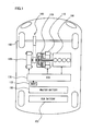
Fig. 1 is a schematic structural view showing a plug-in hybrid vehicle. -
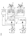
Fig. 2 is a view showing an electric system of a plug-in hybrid vehicle (Part 1). -
Fig. 3 is a view showing an electric system of a plug-in hybrid vehicle (Part 2). -
Fig. 4 is a view showing a connector of a charging cable. -
Fig. 5 is a functional block diagram of an ECU. -
Fig. 6 is a view showing an upper limit value and a lower limit value of SOC in a normal mode. -
Fig. 7 is a view showing an upper limit value and a lower limit value of SOC of a master battery in an EV priority mode. -
Fig. 8 is a view showing a lower limit value of SOC of a sub battery in an EV priority mode. -
Fig. 9 is a view showing the SOC of the master battery and the SOC of the sub battery in an EV priority mode. -
Fig. 10 is a flowchart showing a control structure of a program executed by an ECU. - Hereinafter, embodiments of the present invention will be described with reference to the drawings. In the following description, identical parts are denoted by identical reference numerals. The name and the function thereof are also identical. Therefore, detailed description thereof will not be repeated.
- Referring to
Fig. 1 , a plug-in hybrid vehicle equipped with a control device according to an embodiment of the present invention will be described. The vehicle is equipped with anengine 100, a first MG (Motor Generator) 110, asecond MG 120, apower split device 130, areduction gear 140, amaster battery 150, and asub battery 152. -
Engine 100,first MG 110,second MG 120,master battery 150, andsub battery 152 are controlled by an ECU (Electronic Control Unit) 170.ECU 170 may be split into a plurality of ECUs. - This vehicle travels by a driving force from at least either one of
engine 100 andsecond MG 120. More specifically, the plug-in hybrid vehicle travels while switching a HV travel mode and an EV travel mode automatically or manually. - In the HV travel mode, the vehicle travels while automatically switching at least either one or both of
engine 100 andsecond MG 120 as a driving source depending on the operating state. In the EV travel mode, the vehicle travels using onlysecond MG 120 as a driving source. Also in the EV travel mode,engine 100 may operate for electric power generation and the like. -
Engine 100,first MG 110, andsecond MG 120 are connected viapower split device 130. The power generated byengine 100 is split into two routes bypower split device 130. One route drivesfront wheels 160 viareduction gear 140. The other route drivesfirst MG 110 to generate electric power. -
First MG 110 is a three-phase AC rotating electric machine having a U-phase coil, a V-phase coil, and a W-phase coil.First MG 110 generates electric power by the power ofengine 100 split bypower split device 130. The electric power generated byfirst MG 110 is appropriately used depending on the travel state of the vehicle, and states of SOCs ofmaster battery 150 andsub battery 152. For example, during normal traveling, the electric power generated byfirst MG 110 directly drivessecond MG 120. On the other hand, when the SOC ofmaster battery 150 orsub battery 152 is lower than a predetermined value, the electric power generated byfirst MG 110 is converted from alternating current to direct current by an inverter as will be described later. Then it is stored inmaster battery 150 orsub battery 152 after adjustment of voltage by a converter as will be described later. - When
first MG 110 operates as a generator,first MG 110 generates a negative torque. Here, the negative torque refers to such a torque that will be a load onengine 100. Whenfirst MG 110 operates as a motor while it is supplied with electric power,first MG 110 generates a positive torque. Here, the positive torque refers to such a torque that will not be a load onengine 100, namely, a torque that assists rotation ofengine 100. The same also applies tosecond MG 120. -
Second MG 120 is a three-phase AC rotating electric machine having a U-phase coil, a V-phase coil, and a W-phase coil.Second MG 120 is driven by the electric power of at least either of electric power stored inmaster battery 150 andsub battery 152 and the electric power generated byfirst MG 110. - The driving force of
second MG 120 is transmitted tofront wheels 160 viareduction gear 140. As a result,second MG 120assists engine 100 and makes the vehicle travel by the driving force fromsecond MG 120. In place offront wheels 160, rear wheels may be driven. - At the time of regenerative braking of the plug-in hybrid vehicle,
second MG 120 is driven byfront wheels 160 viareduction gear 140, andsecond MG 120 operates as a generator. As a result,second MG 120 operates as a regenerative brake that converts the breaking energy to the electric power. The electric power generated bysecond MG 120 is stored inmaster battery 150 orsub battery 152. - Power split
device 130 is implemented by a planetary gear including a sun gear, a pinion gear, a carrier, and a ring gear. The pinion gear meshes with the sun gear and the ring gear. The carrier supports the pinion gear to be able to rotate. The sun gear is connected to a rotation axis offirst MG 110. The carrier is connected to a crank shaft ofengine 100. The ring gear is connected to a rotation axis ofsecond MG 120 andreduction gear 140. - As a result of connection of
engine 100,first MG 110, andsecond MG 120 viapower split device 130 implemented by a planetary gear, rotation speeds ofengine 100,first MG 110, andsecond MG 120 have the relation connected by a straight line in a nomographic chart. - Returning to
Fig. 1 ,master battery 150 andsub battery 152 are realized by an assembled battery formed by serially connecting a plurality of battery modules each including integrated plural battery cells. Voltages ofmaster battery 150 andsub battery 152 are, for example, about 200V.Master battery 150 andsub battery 152 are charged with electric power supplied from a electric power source external to the vehicle, as well as fromfirst MG 110 andsecond MG 120. - Capacities of
master battery 150 and sub battery 152 (maximum charge amount that can be charged) are identical or substantially identical. - The plug-in hybrid vehicle in the present embodiment is further equipped with a
navigation device 172.Navigation device 172 has a function of predicting the arrival time to the destination inputted by an operator base on, for example, the current position of the plug-in hybrid vehicle, the vehicle speed, and map data including a distance. - Referring to
Fig. 2 , an electric system of the plug-in hybrid vehicle will be further described. The plug-in hybrid vehicle is provided with amaster converter 200, asub converter 202, afirst inverter 210, asecond inverter 220, a master SMR (System Main Relay) 230, asub SMR 232, acharger 240, and aninlet 250. -
Master converter 200 andsub converter 202 include a reactor, two npn transistors, and two diodes. The reactor is connected at its one end with a positive electrode side of each battery and connected at its other end with a connection point between the two npn transistors. - The two npn transistors are connected in series. The npn transistor is controlled by
ECU 170. Between a collector and an emitter of each npn transistor, a diode is connected so that the current flows from the emitter side to the collector side. - As the npn transistor, for example, IGBT (Insulated Gate Bipolar Transistor) may be used. In place of the npn transistor, a power switching device such as power MOSFET (Metal Oxide Semiconductor Field-Effect Transistor) may be used.
- When the electric power discharged from
master battery 150 is supplied tofirst MG 110 orsecond MG 120, the voltage is boosted bymaster converter 200. Contrarily, whenmaster battery 150 is charged with the electric power generated byfirst MG 110 orsecond MG 120, the voltage is decreased bymaster converter 200. - Similarly, when the electric power discharged from
sub battery 152 is supplied tofirst MG 110 orsecond MG 120, the voltage is boosted bysub converter 202. Contrarily, whensub battery 152 is charged with the electric power generated byfirst MG 110 orsecond MG 120, the voltage is decreased bysub converter 202. - A system voltage VH between each converter and each inverter is detected by a
voltage sensor 180. A detection result ofvoltage sensor 180 is transmitted toECU 170. -
First inverter 210 includes a U-phase arm, a V-phase arm, and a W-phase arm. The U-phase arm, the V-phase arm, and the W-phase arm are connected in parallel. Each of the U-phase arm, the V-phase arm, and the W-phase arm has two npn transistors that are connected in series. Between a collector and an emitter of each npn transistor, a diode for making a current flow from the emitter side to the collector side is connected. A connection point of each npn transistor in each arm is connected to an end part different from aneutral point 112 of each coil offirst MG 110. -
First inverter 210 converts a direct current supplied frommaster battery 150 orsub battery 152 to an alternating current and supplies it tofirst MG 110.First inverter 210 converts an alternating current generated byfirst MG 110 to a direct current. -
Second inverter 220 includes a U-phase arm, a V-phase arm, and a W-phase arm. The U-phase arm, the V-phase arm, and the W-phase arm are connected in parallel. Each of the U-phase arm, the V-phase arm, and the W-phase arm has two npn transistors that are connected in series. Between a collector and an emitter of each npn transistor, a diode for making a current flow from the emitter side to the collector side is connected. A connection point of each npn transistor in each arm is connected to an end part different from aneutral point 122 of each coil ofsecond MG 120. -
Second inverter 220 converts a direct current supplied frommaster battery 150 orsub battery 152 to an alternating current, and supplies it tosecond MG 120.Second inverter 220 converts an alternating current generated bysecond MG 120 to a direct current. -
Master converter 200,sub converter 202,first inverter 210, andsecond inverter 220 are controlled byECU 170. -
Master SMR 230 is provided betweenmaster battery 150 andcharger 240.Master SMR 230 is a relay for switching the connected state and the disconnected state betweenmaster battery 150 and the electric system. Whenmaster SMR 230 is in an opened state,master battery 150 is disconnected from the electric system. Whenmaster SMR 230 is in a closed state,master battery 150 is connected to the electric system. - In other words, when
master SMR 230 is in the opened state,master battery 150 is electrically disconnected frommaster converter 200,charger 240 and the like. Whenmaster SMR 230 is in the closed state,master battery 150 is electrically connected withmaster converter 200,charger 240 and the like. -
Sub SMR 232 is provided betweensub battery 152 andsub converter 202.Sub SMR 232 is a relay for switching a connected state and a disconnected state betweensub battery 152 and the electric system. Whensub SMR 232 is in an opened state,sub battery 152 is disconnected from the electric system. Whensub SMR 232 is in a closed state,sub battery 152 is connected to the electric system. - That is, when
sub SMR 232 is in the opened state,sub battery 152 is electrically disconnected fromsub converter 202,charger 240 and the like. Whensub SMR 232 is in the closed state,sub battery 152 is electrically connected withsub converter 202,charger 240 and the like. - States of
master SMR 230 andsub SMR 232 are controlled byECU 170. For example, whenECU 170 starts up,master SMR 230 andsub SMR 232 are closed.
WhenECU 170 stops,master SMR 230 andsub SMR 232 are opened. -
Charger 240 is connected betweenmaster battery 150 andmaster converter 200. As shown inFig. 3 ,charger 240 includes an AC/DC converter circuit 242, a DC/AC converter circuit 244, aninsulation transformer 246, and arectifier circuit 248. - AC/
DC converter circuit 242 is implemented by a single-phase bridge circuit. AC/DC converter circuit 242 converts AC electric power to DC electric power based on a driving signal fromECU 170. AC/DC converter circuit 242 also functions as a boost chopper circuit that boosts the voltage by using a coil as a reactor. - DC/
AC converter circuit 244 is implemented by a single-phase bridge circuit. DC/AC converter circuit 244 converts DC electric power to high frequency AC electric power based on a driving signal fromECU 170 and outputs it toinsulation transformer 246. -
Insulation transformer 246 includes a core formed of a magnetic material, and a primary coil and a secondary coil wound around the core. The primary coil and the secondary coil are electrically insulated, and are connected to DC/AC converter circuit 244 andrectifier circuit 248, respectively.Insulation transformer 246 converts the high frequency AC electric power received from DC/AC converter circuit 244 to a voltage level corresponding to a winding number ratio between the primary coil and the secondary coil, and outputs it torectifier circuit 248.Rectifier circuit 248 rectifies AC electric power outputted frominsulation transformer 246 to DC electric power. - A voltage across AC/
DC converter circuit 242 and DC/AC converter circuit 244 (terminal-to-terminal voltage of smoothing capacitor) is detected byvoltage sensor 182, and a signal representing the detection result is inputted toECU 170. An output current ofcharger 240 is detected by acurrent sensor 184, and a signal representing the detection result is inputted toECU 170. Further, temperature ofcharger 240 is detected by atemperature sensor 186, and a signal representing the detection result is inputted toECU 170. -
ECU 170 generates a driving signal for drivingcharger 240 and outputs it to charger 240 whenmaster battery 150 orsub battery 152 is charged from a electric power source external to the vehicle. -
ECU 170 has a function of detecting a fail ofcharger 240, as well as a function of controllingcharger 240. When the voltage detected byvoltage sensor 182, the current detected bycurrent sensor 184, the temperature detected bytemperature sensor 186 and so on are equal to or more than thresholds, a fail ofcharger 240 is detected. -
Inlet 250 is provided, for example, in a lateral part of the plug-in hybrid vehicle. Toinlet 250, aconnector 310 of a chargingcable 300 that connects the plug-in hybrid vehicle and an externalelectric power source 402 is connected. - Charging
cable 300 that connects the plug-in hybrid vehicle and externalelectric power source 402 includesconnector 310, aplug 320, and a CCID (Charging Circuit Interrupt Device) 330. -
Connector 310 of chargingcable 300 is connected toinlet 250 provided in the plug-in hybrid vehicle.Connector 310 is provided with aswitch 312. Whenswitch 312 is closed in the condition thatconnector 310 of chargingcable 300 is connected toinlet 250 provided in the plug-in hybrid vehicle, a connector signal CNCT indicating thatconnector 310 of chargingcable 300 is being connected withinlet 250 provided in the plug-in hybrid vehicle is inputted toECU 170. -
Switch 312 opens/closes in cooperation with a latch that latchesconnector 310 of chargingcable 300 toinlet 250 of the hybrid vehicle. The latch oscillates as an operator presses a button provided inconnector 310. - For example, when an operator leaves his/her finger from a
button 314 ofconnector 310 shown inFig. 4 in the condition thatconnector 310 of chargingcable 300 is connected withinlet 250 provided in the hybrid vehicle,latch 316 engages withinlet 250 provided in the hybrid vehicle, and switch 312 closes. As the operator pressesbutton 314,latch 316 andinlet 250 are released from engagement, and switch 312 opens. The method for opening or closingswitch 312 is not limited to this. - Returning to
Fig. 3 , plug 320 of chargingcable 300 is connected to asocket 400 provided in a house.Socket 400 is supplied with AC electric power from externalelectric power source 402 of the plug-in hybrid vehicle. -
CCID 330 has arelay 332 and acontrol pilot circuit 334. In the state that relay 332 is open, the route for supplying electric power from externalelectric power source 402 of the plug-in hybrid vehicle to the plug-in hybrid vehicle is blocked. In the state that relay 332 is closed, electric power supply from externalelectric power source 402 of the plug-in hybrid vehicle to the plug-in hybrid vehicle is allowed. The state ofrelay 332 is controlled byECU 170 in the condition thatconnector 310 of chargingcable 300 is connected toinlet 250 of the plug-in hybrid vehicle. -
Control pilot circuit 334 sends a pilot signal (square wave signal) CPLT to a control pilot line in the condition that plug 320 of chargingcable 300 is connected tosocket 400, namely to externalelectric power source 402, andconnector 310 is connected toinlet 250 provided in the plug-in hybrid vehicle. The pilot signal is oscillated by an oscillator provided incontrol pilot circuit 334. -
Control pilot circuit 334 is able to output a constant pilot signal CPLT when plug 320 of chargingcable 300 is connected tosocket 400 even ifconnector 310 is removed frominlet 250 provided in the plug-in hybrid vehicle.ECU 170 is unable to detect a pilot signal CPLT outputted in the condition thatconnector 310 is removed frominlet 250 provided in the plug-in hybrid vehicle. - When plug 320 of charging
cable 300 is connected tosocket 400, andconnector 310 is connected toinlet 250 of the plug-in hybrid vehicle,control pilot circuit 334 oscillates a pilot signal CPLT having a predetermined pulse width (duty cycle). - The plug-in hybrid vehicle is notified of a current capacity that can be supplied by a pulse width of pilot signal CPLT. For example, the plug-in hybrid vehicle is notified of a current capacity of charging
cable 300. The pulse width of pilot signal CPLT is constant irrespective of the voltage and the current of externalelectric power source 402. - On the other hand, the pulse width of pilot signal CPLT can vary with the kind of the charging cable that is used. To be more specific, the pulse width of pilot signal CPLT can be determined for each kind of charging cable.
- In the present embodiment, in the condition that the plug-in hybrid vehicle and external
electric power source 402 are connected by chargingcable 300,master battery 150 orsub battery 152 is charged with the electric power supplied from externalelectric power source 402. At the time of chargingmaster battery 150 orsub battery 152,relay 332 inmaster SMR 230,sub SMR 232, andCCID 330 is closed. - An AC voltage VAC of external
electric power source 402 is detected by avoltage sensor 188 provided inside the plug-in hybrid vehicle. The detected voltage VAC is transmitted toECU 170. - Referring to
Fig. 5 , a function ofECU 170 will be further described. The function described below may be implemented by software, or by hardware. -
ECU 170 has afirst control unit 500, asetting unit 510, asecond control unit 520, and athird control unit 530. -
First control unit 500 controls the SOCs ofmaster battery 150 andsub battery 152 so that the SOC varies within the range from a predetermined upper limit value and lower limit value in the HV travel mode as shown inFig. 6 . The SOCs ofmaster battery 150 andsub battery 152 are indirectly controlled by controllingengine 100,first MG 110, andsecond MG 120.Fig. 6 shows an upper limit value and a lower limit value of SOC in a normal mode. - The control may be conducted such that the SOCs of
master battery 150 andsub battery 152 are equal to predetermined target values. - Returning to
Fig. 5 , settingunit 510 includes afirst setting unit 511 and asecond setting unit 512. First settingunit 511 sets an upper limit value and a lower limit value of SOC ofmaster battery 150 for an EV priority mode when the condition that execution of charging with the electric power supplied from the source external to the plug-in hybrid vehicle is predicted is satisfied. Here, the EV priority mode means a mode capable of executing travel in the EV travel mode preferentially. - In the EV priority mode, the upper limit value and the lower limit value of the SOC of
master battery 150 are set to be higher than those in the normal mode as shown inFig. 7 . - That is, when the condition that execution of charging with the electric power supplied from the source external to the plug-in hybrid vehicle is predicted is satisfied, the upper limit value and the lower limit value of the SOC of
master battery 150 are set so that the SOC ofmaster battery 150 is higher than the SOC of the case where the condition is not satisfied. - As a result, as shown by the continuous line in
Fig. 7 , it is possible to make the SOC ofmaster battery 150 higher in the EV priority mode than in the normal mode. - The condition that execution of charging with the electric power supplied from the source external to the plug-in hybrid vehicle is predicted is, for example, a condition that time at which the plug-in hybrid vehicle is predicted to arrive at the location (for example, home) where it is defined that charging with the electric power supplied from the source external to the plug-in hybrid vehicle is possible is included in a time zone where the electric power rate is set to be lower than that in other time zones. In other words, when it is predicted that charging can be executed in the time zone where electric power rate is lower than that in the daytime, the setting is made so that the upper limit value and the lower limit value of the SOC of
master battery 150 are high. Besides, other condition than the aforementioned condition such as a condition that the expected arrival time is in the night may be employed. - Either one of the upper limit value and the lower limit value may be set to be high. Also the setting may be made so that the upper limit value and the lower limit value are identical between the case where the condition is satisfied and the case where the condition is not satisfied. Further, the setting may be made so that the target value of the SOC of
master battery 150 is high when the condition is satisfied, or the setting may be made so that the target values are identical between the case where the condition is satisfied and the case where the condition is not satisfied. -
Second setting unit 512 sets a lower limit value of the SOC ofsub battery 152 for EV priority mode so that the SOC ofsub battery 152 is low when the condition that execution of charging with the electric power supplied from the source external to the plug-in hybrid vehicle is predicted is satisfied. - In the EV priority mode, the setting is made so that the lower limit value of the SOC of
sub battery 152 is lower than that in the normal mode as shown inFig. 8 . That is, when the condition that execution of charging with the electric power supplied from the source external to the plug-in hybrid vehicle is predicted is satisfied, the lower limit value of the SOC ofsub battery 152 is made low so that the SOC ofsub battery 152 is lower than the SOC of the case where the condition is not satisfied. As a result, it is possible to make the SOC ofsub battery 152 in the EV priority mode lower than the SOC in the normal mode. - Also the setting may be made so that only the upper limit value is low, or both the upper limit value and the lower limit value are low. Also the setting may be made so that the target value of the SOC of
master battery 150 is low when the condition is satisfied. - Since the capacity of
master battery 150 and the capacity ofsub battery 152 are equivalent, the SOC ofsub battery 152 becomes lower than the SOC ofmaster battery 150 by causing the SOC ofmaster battery 150 to be higher than the SOC of the case where the condition is not satisfied and the SOC ofsub battery 152 to be lower than the SOC of the case where the condition is not satisfied. - That is, when the condition that execution of charging with the electric power supplied from the source external to the plug-in hybrid vehicle is predicted is satisfied, setting
unit 510 sets the upper limit values and the lower limit values of the SOC ofmaster battery 150 and the SOC ofsub battery 152 so that the SOC ofsub battery 152 is lower than the SOC ofmaster battery 150 as shown inFig. 9 , by causing the SOC ofmaster battery 150 to be higher than the SOC of the case where the condition is not satisfied and the SOC ofsub battery 152 to be lower than the SOC of the case where the condition is not satisfied. - The target values of the SOC of
master battery 150 and the SOC ofsub battery 152 may be set so that the SOC ofsub battery 152 is lower than the SOC ofmaster battery 150. -
Second control unit 520 controls the SOC ofsub battery 152 in the HV travel mode to decrease to the lower limit value as shown inFig. 8 andFig. 9 when the condition that execution of charging with the electric power supplied from the source external to the plug-in hybrid vehicle is predicted is satisfied. - That is, by driving
second MG 120 using the electric power stored insub battery 152, the plug-in hybrid vehicle travels preferentially in the EV travel mode until the SOC ofsub battery 152 decreases to the lower limit value as shown inFig. 8 andFig. 9 . -
Third control unit 530 controls the vehicle to travel in the HV travel mode after the SOC ofsub battery 152 becomes lower than the SOC ofmaster battery 150, namely, after the SOC ofsub battery 152 decreases to the lower limit value, as shown inFig. 8 andFig. 9 . - Referring to
Fig. 10 , a control structure of a program executed byECU 170 will be described. - In step (hereinafter, step is abbreviated as S) 100,
ECU 170 predicts the time at which the plug-in hybrid vehicle arrives at the location (for example, home) where it is defined that charging with the electric power supplied from the source external to the plug-in hybrid vehicle is possible. - In S102,
ECU 170 determines whether time at which the plug-in hybrid vehicle arrives at the location where it is defined that charging with the electric power supplied from the source external to the plug-in hybrid vehicle is possible is included in a time zone where electric power rate is set lower than that in other time zones. - When the time at which the plug-in hybrid vehicle arrives at the location where it is defined that charging with the electric power supplied from the source external to the plug-in hybrid vehicle is possible is included in the time zone where electric power rate is set lower than that in other time zones (YES in S102), the process proceeds to
S 108. When it is not so (NO in S 102), the process proceeds toS 104. - In S104,
ECU 170 sets upper limit values and lower limit values of the SOC ofmaster battery 150 andsub battery 152 in the normal mode. - In S106,
ECU 170 controls the SOCs ofmaster battery 150 andsub battery 152 so that the SOCs vary within the range between the defined upper limit value and lower limit value. - In S108,
ECU 170 sets the upper limit value and the lower limit value of the SOC ofmaster battery 150 for the EV priority mode so that they are higher than those in the normal mode. - In
S 110,ECU 170 sets the lower limit value of the SOC ofsub battery 152 for the EV priority mode so that it is lower than that in the normal mode. - In
S 112,ECU 170 controls the SOC ofmaster battery 150 so that the SOC varies within the range between the defined upper limit value and lower limit value, and controls the SOC ofsub battery 152 so that it decreases to the lower limit value. - In
S 114,ECU 170 controls the vehicle to travel in the HV travel mode. An operation of the control device according to the present embodiment based on the structure and flow chart as described above will be described. - During travel of the plug-in hybrid vehicle, the time at which the plug-in hybrid vehicle arrives at the location (for example, home) where it is defined that charging with the electric power supplied from the source external to the plug-in hybrid vehicle is possible is predicted by using the navigation device (S100).
- When the time at which the plug-in hybrid vehicle arrives at the location where it is defined that charging with the electric power supplied from the source external to the plug-in hybrid vehicle is possible is not included in the time zone where the electric power rate is set to be lower than that in other time zones (NO in S 102), the upper limit values and the lower limit values of the SOCs of
master battery 150 andsub battery 152 in the normal mode are set (S104). - The
SOCs master battery 150 andsub battery 152 are controlled so that the SOCs vary within the range between the defined upper limit value and lower limit value (S106). - On the other hand, when the time at which the plug-in hybrid vehicle arrives at the location where it is defined that charging with the electric power supplied from the source external to the plug-in hybrid vehicle is possible is included in the time zone where the electric power rate is set to be lower than that in other time zones (YES in S102), the upper limit value and the lower limit value of the SOC of
master battery 150 are set to be higher than those in the normal mode (S108). Also, the lower limit value of the SOC ofsub battery 152 is set to be lower than that in the normal mode (S 110). - Further, the SOC of
master battery 150 is controlled so that the SOC varies within the range between the defined upper limit value and lower limit value and the SOC ofsub battery 152 is controlled so that it decreases to the lower limit value (S 112). Then the vehicle is controlled so that it travels in the HV travel mode (S 114). - As a result, it is possible to make the SOC of
sub battery 152 lower than the SOC ofmaster battery 150, and to store the electric power required for traveling in the HV travel mode inmaster battery 150 during traveling of the plug-in hybrid vehicle. Therefore, when charging is executed with electric power supplied from the external electric power source of the vehicle, it is possible to increase the charging amount ofsub battery 152 using low-cost electric power in the middle of the night. As a result, it is possible to reduce the cost required for charging. On the other hand, even when charging is not executed for some reason,second MG 120 can be driven by using the electric power stored inmaster battery 150. Therefore, even when charging is not executed, it is possible to ensure the motive power performance. - It should be noted that the embodiments disclosed herein are given in every respect for exemplification rather than limitation. The scope of the present invention is defined by claims rather than by the embodiments described above.
- 100 engine, 110 first MG, 120 second MG, 130 power split device, 140 reduction gear, 150 master battery, 152 sub battery, 160 front wheel, 170 ECU, 172 navigation device, 200 master converter, 202 sub converter, 210 first inverter, 220 second inverter, 230 master SMR, 232 sub SMR, 240 charger, 242 AC/DC converter circuit, 244 DC/AC converter circuit, 246 insulation transformer, 248 rectifier circuit, 250 inlet, 300 charging cable, 310 connector, 312 switch, 314 button, 316 latch, 320 plug, 332 relay, 334 control pilot circuit, 400 socket, 402 electric power supply, 500 first control unit, 511 first setting unit, 512 second setting unit, 520 second control unit, 530 third control unit.
Claims (7)
- A vehicle comprising:an internal combustion engine (100) as a driving source;a rotating electric machine (120) as a driving source;a generator (110) for generating electric power by a driving force of said internal combustion engine (100);a first battery (150) for storing electric power supplied from a source external to a vehicle and electric power generated by said generator (110) and supplying the stored electric power to said rotating electric machine (120);a second battery (152) connected in parallel with said first battery (150), for storing electric power supplied from the source external to said vehicle and electric power generated by said generator (110) and supplying the stored electric power to said rotating electric machine (120); anda control unit (170), whereinsaid control unit (170)controls a state of charge of each of said batteries (150, 152) according to at least either one of a target range and a target value of the state of charge of each of said batteries (150, 152),sets at least either one of the target range and the target value of the state of charge of each of said batteries (150, 152) so that the state of charge of said second battery (152) is lower than the state of charge of said first battery (150) by causing, when a condition that execution of charging with electric power supplied from the source external to said vehicle is predicted is satisfied, the state of charge of said first battery (150) to be equal to or more than the state of charge of said first battery (150) in the case where said condition is not satisfied and the state of charge of said second battery (152) to be lower than the state of charge of said second battery (152) in the case where said condition is not satisfied, andcontrols said internal combustion engine (100) and said rotating electric machine (120) so that said vehicle travels by a driving force of at least either one of said internal combustion engine (100) and said rotating electric machine (120) after the state of charge of said second battery (152) becomes lower than the state of charge of said first battery (150).
- The vehicle according to claim 1, wherein
the condition that execution of charging with electric power supplied from the source external to said vehicle is predicted is a condition that time at which said vehicle is predicted to arrive at a location where it is defined that charging with electric power supplied from the source external to said vehicle is possible is included in a time zone where electric power rate is set to be lower than that in other time zones. - The vehicle according to claim 1, wherein
said control unit (170) controls the state of charge of said second battery (152) to decrease to a lower limit value. - A control method for a vehicle equipped with an internal combustion engine (100) as a driving source; a rotating electric machine (120) as a driving source; a generator (110) for generating electric power by a driving force of said internal combustion engine (100); a first battery (150) for storing electric power supplied from a source external to a vehicle and electric power generated by said generator (110) and supplying the stored electric power to said rotating electric machine (120); and a second battery (152) connected in parallel with said first battery (150), for storing electric power supplied from the source external to said vehicle and electric power generated by said generator (110) and supplying the stored electric power to said rotating electric machine (120), the method comprising the steps of:controlling a state of charge of each of said batteries (150, 152) according to at least either one of a target range and a target value of the state of charge of each of said batteries (150, 152);setting at least either one of the target range and the target value of a state of charge of each of said batteries (150, 152) so that the state of charge of said second battery (152) is lower than the state of charge of said first battery (150), by causing, when a condition that execution of charging with electric power supplied from the source external to said vehicle is predicted is satisfied, the state of charge of said first battery (150) to be equal to or more than the state of charge of said first battery (150) in the case where said condition is not satisfied and the state of charge of said second battery (152) to be lower than the state of charge of said second battery (152) in the case where said condition is not satisfied; andcontrolling said internal combustion engine (100) and said rotating electric machine (120) so that said vehicle travels by a driving force of at least either one of said internal combustion engine (100) and said rotating electric machine (120) after the state of charge of said second battery (152) becomes lower than the state of charge of said first battery (150).
- The control method for a vehicle according to claim 4, wherein
the condition that execution of charging with electric power supplied from the source external to said vehicle is predicted is a condition that time at which said vehicle is predicted to arrive at a location where it is defined that charging with electric power supplied from the source external to said vehicle is possible is included in a time zone where electric power rate is set to be lower than that in other time zones. - The control method for a vehicle according to claim 4, further comprising
the step of controlling the state of charge of said second battery (152) to decrease to a lower limit value. - A control device for a vehicle equipped with an internal combustion engine (100) as a driving source; a rotating electric machine (120) as a driving source; a generator (110) for generating electric power by a driving force of said internal combustion engine (100); a first battery (150) for storing electric power supplied from a source external to a vehicle and electric power generated by said generator (110) and supplying the stored electric power to said rotating electric machine (120); and a second battery (152) connected in parallel with said first battery (150), for storing electric power supplied from the source external to said vehicle and electric power generated by said generator (110) and supplying the stored electric power to said rotating electric machine (120), the control device for a vehicle comprising:means (500) for controlling a state of charge of each of said batteries (150, 152) according to at least either one of a target range and a target value of the state of charge of each of said batteries (150, 152);means (510) for setting at least either one of the target range and the target value of the state of charge of each of said batteries (150, 152) so that the state of charge of said second battery (152) is lower than a state of charge of said first battery (150), by causing, when a condition that execution of charging with electric power supplied from the source external to said vehicle is predicted is satisfied, the state of charge of said first battery (150) to be equal to or more than the state of charge of said first battery (150) in the case where said condition is not satisfied and the state of charge of said second battery (152) to be lower than the state of charge of said second battery (152) in the case where said condition is not satisfied; andmeans (530) for controlling said internal combustion engine (100) and said rotating electric machine (120) so that said vehicle travels by a driving force of at least either one of said internal combustion engine (100) and said rotating electric machine (120) after the state of charge of said second battery (152) becomes lower than the state of charge of said first battery (150).
Applications Claiming Priority (2)
| Application Number | Priority Date | Filing Date | Title |
|---|---|---|---|
| JP2008226009A JP4466772B2 (en) | 2008-09-03 | 2008-09-03 | Vehicle control device |
| PCT/JP2009/058899 WO2010026801A1 (en) | 2008-09-03 | 2009-05-13 | Vehicle, vehicle control method and control device |
Publications (3)
| Publication Number | Publication Date |
|---|---|
| EP2332798A1 EP2332798A1 (en) | 2011-06-15 |
| EP2332798A4 EP2332798A4 (en) | 2013-03-13 |
| EP2332798B1 true EP2332798B1 (en) | 2014-08-27 |
Family
ID=41796976
Family Applications (1)
| Application Number | Title | Priority Date | Filing Date |
|---|---|---|---|
| EP09811330.1A Not-in-force EP2332798B1 (en) | 2008-09-03 | 2009-05-13 | Vehicle, vehicle control method and control device |
Country Status (5)
| Country | Link |
|---|---|
| US (1) | US8469857B2 (en) |
| EP (1) | EP2332798B1 (en) |
| JP (1) | JP4466772B2 (en) |
| CN (1) | CN102143873B (en) |
| WO (1) | WO2010026801A1 (en) |
Families Citing this family (32)
| Publication number | Priority date | Publication date | Assignee | Title |
|---|---|---|---|---|
| JP4179351B2 (en) * | 2006-07-07 | 2008-11-12 | トヨタ自動車株式会社 | Power supply system, vehicle equipped with the same, method for controlling power supply system, and computer-readable recording medium recording a program for causing computer to execute control of power supply system |
| CN102884700B (en) * | 2010-07-28 | 2016-01-20 | 松下知识产权经营株式会社 | The control method of the control device of electric power supply system, electric power supply system, the method for operation of electric power supply system and electric power supply system |
| TWI413340B (en) * | 2010-11-17 | 2013-10-21 | 財團法人工業技術研究院 | Method and apparatus to extend plug-in hybrid electric vehicular battery life |
| CN103262386A (en) * | 2010-12-17 | 2013-08-21 | 松下电器产业株式会社 | Power supply device and power supply method |
| JP5605436B2 (en) * | 2010-12-20 | 2014-10-15 | トヨタ自動車株式会社 | Electric vehicle and control method thereof |
| US9333863B2 (en) * | 2011-08-25 | 2016-05-10 | Toyota Jidosha Kabushiki Kaisha | Vehicle, and control method and control device for vehicle |
| EP2570284B1 (en) * | 2011-09-14 | 2016-10-26 | V2 Plug-in Hybrid Vehicle Partnership Handelsbolag | Plug-in hybrid electric vehicle |
| US8838385B2 (en) * | 2011-12-20 | 2014-09-16 | Ford Global Technologies, Llc | Method and apparatus for vehicle routing |
| JP2013146129A (en) * | 2012-01-13 | 2013-07-25 | Iyo Matsuyama Hitech Kk | Power storage/generation system |
| WO2013154093A1 (en) * | 2012-04-09 | 2013-10-17 | 日産自動車株式会社 | Control device for hybrid vehicle, management system for hybrid vehicle, and management method for hybrid vehicle |
| KR102040632B1 (en) * | 2012-05-11 | 2019-11-05 | 후지 덴키 가부시키가이샤 | Motor drive device |
| US20150127203A1 (en) * | 2012-05-15 | 2015-05-07 | Toyota Jidosha Kabushiki Kaisha | Vehicle travel control assistance device |
| US9580065B2 (en) * | 2012-07-17 | 2017-02-28 | Altigreen Propulsion Labs Private Limited | Dual-structured electric drive and power system for hybrid vehicles |
| US9441599B2 (en) | 2012-07-17 | 2016-09-13 | Altigreen Propulsion Labs Private Limited | Induction motor-permanent magnet generator tandem configuration starter-generator for hybrid vehicles |
| GB2517470B (en) | 2013-08-21 | 2016-07-20 | Jaguar Land Rover Ltd | Hybrid electric vehicle controller and method |
| JP5920306B2 (en) * | 2013-10-02 | 2016-05-18 | トヨタ自動車株式会社 | Hybrid vehicle and control method of hybrid vehicle |
| FR3015411B1 (en) * | 2013-12-19 | 2016-01-22 | Peugeot Citroen Automobiles Sa | TORQUE SETTING CALCULATION METHOD FOR AN ELECTRIC MACHINE COUPLED TO A THERMAL MOTOR OF A HYBRID VEHICLE |
| KR20150121919A (en) * | 2014-04-22 | 2015-10-30 | 현대모비스 주식회사 | Apparatus for Charging Battery and Method Thereof |
| KR102263726B1 (en) * | 2014-10-08 | 2021-06-11 | 현대모비스 주식회사 | Power Supply Apparatus and Method for Hybrid Vehicle |
| US9649944B2 (en) * | 2015-04-21 | 2017-05-16 | Atieva, Inc. | Method of providing constant driving range in an electric vehicle |
| JP6432534B2 (en) * | 2016-01-18 | 2018-12-05 | スズキ株式会社 | Hybrid vehicle |
| JP2017204407A (en) * | 2016-05-12 | 2017-11-16 | トヨタ自動車株式会社 | Fuel cell system and control method thereof |
| EP3497437B1 (en) | 2016-08-15 | 2023-03-01 | Royal Melbourne Institute Of Technology | Gas sensor capsule |
| CN107782325A (en) * | 2016-08-30 | 2018-03-09 | 中兴通讯股份有限公司 | A kind of method and apparatus for transmitting navigation information |
| JP2018103747A (en) * | 2016-12-26 | 2018-07-05 | スズキ株式会社 | Hybrid vehicle |
| JP6930306B2 (en) * | 2017-09-05 | 2021-09-01 | トヨタ自動車株式会社 | Electric vehicle |
| JP6897528B2 (en) * | 2017-12-05 | 2021-06-30 | トヨタ自動車株式会社 | Hybrid vehicle control device |
| JP7059761B2 (en) * | 2018-04-03 | 2022-04-26 | トヨタ自動車株式会社 | Vehicle charge / discharge control device |
| JP7086184B2 (en) * | 2018-05-22 | 2022-06-17 | 本田技研工業株式会社 | Electric vehicle and electric vehicle control method |
| JP7056385B2 (en) * | 2018-05-31 | 2022-04-19 | トヨタ自動車株式会社 | Electric vehicle |
| CN109435762B (en) * | 2018-11-08 | 2022-08-05 | 南京华威智能汽车系统有限公司 | Methanol extended-range electric vehicle battery management method, device, equipment and medium |
| JP2020145850A (en) * | 2019-03-06 | 2020-09-10 | トヨタ自動車株式会社 | Electrical power system for vehicle |
Family Cites Families (13)
| Publication number | Priority date | Publication date | Assignee | Title |
|---|---|---|---|---|
| JP3385657B2 (en) * | 1993-08-10 | 2003-03-10 | トヨタ自動車株式会社 | Car navigation system |
| JPH08154307A (en) * | 1994-11-29 | 1996-06-11 | Mitsubishi Motors Corp | Limited fuel use hybrid electric vehicle |
| JP2001069612A (en) * | 1999-08-27 | 2001-03-16 | Yamaha Motor Co Ltd | Hybrid driver |
| US6701880B1 (en) * | 2002-04-12 | 2004-03-09 | Ford Motor Company | Method and apparatus for starting a motor vehicle |
| JP2004178965A (en) * | 2002-11-27 | 2004-06-24 | Nissan Motor Co Ltd | Control device of vehicle |
| JP4281725B2 (en) * | 2005-09-01 | 2009-06-17 | トヨタ自動車株式会社 | Hybrid car |
| JP4525613B2 (en) * | 2006-02-28 | 2010-08-18 | トヨタ自動車株式会社 | Control device for vehicle power transmission device |
| JP4413888B2 (en) * | 2006-06-13 | 2010-02-10 | 株式会社東芝 | Storage battery system, in-vehicle power supply system, vehicle, and method for charging storage battery system |
| JP4905300B2 (en) * | 2006-09-28 | 2012-03-28 | トヨタ自動車株式会社 | Power supply system, vehicle equipped with the same, control method for power supply system, and computer-readable recording medium recording a program for causing a computer to execute the control method |
| JP2008087516A (en) * | 2006-09-29 | 2008-04-17 | Toyota Motor Corp | Hybrid vehicle and drive control method of the same |
| JP4321576B2 (en) * | 2006-10-24 | 2009-08-26 | トヨタ自動車株式会社 | Power supply device and vehicle including the same |
| JP4513812B2 (en) * | 2007-01-04 | 2010-07-28 | トヨタ自動車株式会社 | Vehicle power supply device and vehicle |
| US8271173B2 (en) * | 2007-11-07 | 2012-09-18 | GM Global Technology Operations LLC | Method and apparatus for controlling a hybrid powertrain system |
-
2008
- 2008-09-03 JP JP2008226009A patent/JP4466772B2/en not_active Expired - Fee Related
-
2009
- 2009-05-13 EP EP09811330.1A patent/EP2332798B1/en not_active Not-in-force
- 2009-05-13 WO PCT/JP2009/058899 patent/WO2010026801A1/en active Application Filing
- 2009-05-13 US US13/061,610 patent/US8469857B2/en not_active Expired - Fee Related
- 2009-05-13 CN CN2009801343167A patent/CN102143873B/en not_active Expired - Fee Related
Also Published As
| Publication number | Publication date |
|---|---|
| JP2010058640A (en) | 2010-03-18 |
| CN102143873A (en) | 2011-08-03 |
| EP2332798A4 (en) | 2013-03-13 |
| CN102143873B (en) | 2013-11-13 |
| US20110160019A1 (en) | 2011-06-30 |
| WO2010026801A1 (en) | 2010-03-11 |
| EP2332798A1 (en) | 2011-06-15 |
| JP4466772B2 (en) | 2010-05-26 |
| US8469857B2 (en) | 2013-06-25 |
Similar Documents
| Publication | Publication Date | Title |
|---|---|---|
| EP2332798B1 (en) | Vehicle, vehicle control method and control device | |
| US8186465B2 (en) | Hybrid vehicle and controlling method thereof | |
| KR101036040B1 (en) | Hybrid vehicle | |
| US8659182B2 (en) | Power supply system and electric powered vehicle including power supply system, and method for controlling power supply system | |
| US8538616B2 (en) | Power supply system for electrically powered vehicle, electrically powered vehicle, and method for controlling the same | |
| CN102958740B (en) | Electrically driven vehicle and method of controlling thereof | |
| US8952564B2 (en) | Power source system for electric powered vehicle | |
| US8681457B2 (en) | Power source system for electric powered vehicle and control method therefor | |
| JP5716694B2 (en) | Electric vehicle | |
| EP2700529A1 (en) | Power supply apparatus for electric-powered vehicle, and method of controlling thereof | |
| CN103108769A (en) | Power supply system for vehicle | |
| US20100204860A1 (en) | Control apparatus and control method for vehicle | |
| JP5104898B2 (en) | Electric system power limiting device | |
| CN102458906A (en) | Hybrid vehicle and method for controlling the same | |
| JP5015858B2 (en) | Electric vehicle power supply system and control method thereof | |
| JP2009278706A (en) | Charging apparatus for electric vehicle | |
| JP2012249455A (en) | Electric system in vehicle | |
| JP2010115050A (en) | Power supply system for vehicle | |
| JP5741385B2 (en) | Battery charging system | |
| JP5621264B2 (en) | Vehicle electrical system |
Legal Events
| Date | Code | Title | Description |
|---|---|---|---|
| PUAI | Public reference made under article 153(3) epc to a published international application that has entered the european phase |
Free format text: ORIGINAL CODE: 0009012 |
|
| 17P | Request for examination filed |
Effective date: 20110401 |
|
| AK | Designated contracting states |
Kind code of ref document: A1 Designated state(s): AT BE BG CH CY CZ DE DK EE ES FI FR GB GR HR HU IE IS IT LI LT LU LV MC MK MT NL NO PL PT RO SE SI SK TR |
|
| AX | Request for extension of the european patent |
Extension state: AL BA RS |
|
| DAX | Request for extension of the european patent (deleted) | ||
| RAP1 | Party data changed (applicant data changed or rights of an application transferred) |
Owner name: TOYOTA JIDOSHA KABUSHIKI KAISHA |
|
| A4 | Supplementary search report drawn up and despatched |
Effective date: 20130211 |
|
| RIC1 | Information provided on ipc code assigned before grant |
Ipc: F02D 29/02 20060101ALI20130205BHEP Ipc: B60K 6/445 20071001ALI20130205BHEP Ipc: B60W 10/06 20060101ALI20130205BHEP Ipc: B60W 10/26 20060101AFI20130205BHEP Ipc: B60W 10/08 20060101ALI20130205BHEP Ipc: B60W 20/00 20060101ALI20130205BHEP |
|
| GRAP | Despatch of communication of intention to grant a patent |
Free format text: ORIGINAL CODE: EPIDOSNIGR1 |
|
| INTG | Intention to grant announced |
Effective date: 20140317 |
|
| RIN1 | Information on inventor provided before grant (corrected) |
Inventor name: HARADA, HIRONORI |
|
| GRAS | Grant fee paid |
Free format text: ORIGINAL CODE: EPIDOSNIGR3 |
|
| GRAA | (expected) grant |
Free format text: ORIGINAL CODE: 0009210 |
|
| AK | Designated contracting states |
Kind code of ref document: B1 Designated state(s): AT BE BG CH CY CZ DE DK EE ES FI FR GB GR HR HU IE IS IT LI LT LU LV MC MK MT NL NO PL PT RO SE SI SK TR |
|
| REG | Reference to a national code |
Ref country code: GB Ref legal event code: FG4D |
|
| REG | Reference to a national code |
Ref country code: CH Ref legal event code: EP |
|
| REG | Reference to a national code |
Ref country code: AT Ref legal event code: REF Ref document number: 684368 Country of ref document: AT Kind code of ref document: T Effective date: 20140915 |
|
| REG | Reference to a national code |
Ref country code: IE Ref legal event code: FG4D |
|
| REG | Reference to a national code |
Ref country code: DE Ref legal event code: R096 Ref document number: 602009026337 Country of ref document: DE Effective date: 20141009 |
|
| REG | Reference to a national code |
Ref country code: AT Ref legal event code: MK05 Ref document number: 684368 Country of ref document: AT Kind code of ref document: T Effective date: 20140827 |
|
| REG | Reference to a national code |
Ref country code: LT Ref legal event code: MG4D |
|
| REG | Reference to a national code |
Ref country code: NL Ref legal event code: VDEP Effective date: 20140827 |
|
| PG25 | Lapsed in a contracting state [announced via postgrant information from national office to epo] |
Ref country code: SE Free format text: LAPSE BECAUSE OF FAILURE TO SUBMIT A TRANSLATION OF THE DESCRIPTION OR TO PAY THE FEE WITHIN THE PRESCRIBED TIME-LIMIT Effective date: 20140827 Ref country code: PT Free format text: LAPSE BECAUSE OF FAILURE TO SUBMIT A TRANSLATION OF THE DESCRIPTION OR TO PAY THE FEE WITHIN THE PRESCRIBED TIME-LIMIT Effective date: 20141229 Ref country code: BG Free format text: LAPSE BECAUSE OF FAILURE TO SUBMIT A TRANSLATION OF THE DESCRIPTION OR TO PAY THE FEE WITHIN THE PRESCRIBED TIME-LIMIT Effective date: 20141127 Ref country code: GR Free format text: LAPSE BECAUSE OF FAILURE TO SUBMIT A TRANSLATION OF THE DESCRIPTION OR TO PAY THE FEE WITHIN THE PRESCRIBED TIME-LIMIT Effective date: 20141128 Ref country code: FI Free format text: LAPSE BECAUSE OF FAILURE TO SUBMIT A TRANSLATION OF THE DESCRIPTION OR TO PAY THE FEE WITHIN THE PRESCRIBED TIME-LIMIT Effective date: 20140827 Ref country code: LT Free format text: LAPSE BECAUSE OF FAILURE TO SUBMIT A TRANSLATION OF THE DESCRIPTION OR TO PAY THE FEE WITHIN THE PRESCRIBED TIME-LIMIT Effective date: 20140827 Ref country code: ES Free format text: LAPSE BECAUSE OF FAILURE TO SUBMIT A TRANSLATION OF THE DESCRIPTION OR TO PAY THE FEE WITHIN THE PRESCRIBED TIME-LIMIT Effective date: 20140827 Ref country code: NO Free format text: LAPSE BECAUSE OF FAILURE TO SUBMIT A TRANSLATION OF THE DESCRIPTION OR TO PAY THE FEE WITHIN THE PRESCRIBED TIME-LIMIT Effective date: 20141127 |
|
| REG | Reference to a national code |
Ref country code: DE Ref legal event code: R084 Ref document number: 602009026337 Country of ref document: DE |
|
| PG25 | Lapsed in a contracting state [announced via postgrant information from national office to epo] |
Ref country code: IS Free format text: LAPSE BECAUSE OF FAILURE TO SUBMIT A TRANSLATION OF THE DESCRIPTION OR TO PAY THE FEE WITHIN THE PRESCRIBED TIME-LIMIT Effective date: 20141227 Ref country code: AT Free format text: LAPSE BECAUSE OF FAILURE TO SUBMIT A TRANSLATION OF THE DESCRIPTION OR TO PAY THE FEE WITHIN THE PRESCRIBED TIME-LIMIT Effective date: 20140827 Ref country code: CY Free format text: LAPSE BECAUSE OF FAILURE TO SUBMIT A TRANSLATION OF THE DESCRIPTION OR TO PAY THE FEE WITHIN THE PRESCRIBED TIME-LIMIT Effective date: 20140827 Ref country code: LV Free format text: LAPSE BECAUSE OF FAILURE TO SUBMIT A TRANSLATION OF THE DESCRIPTION OR TO PAY THE FEE WITHIN THE PRESCRIBED TIME-LIMIT Effective date: 20140827 Ref country code: HR Free format text: LAPSE BECAUSE OF FAILURE TO SUBMIT A TRANSLATION OF THE DESCRIPTION OR TO PAY THE FEE WITHIN THE PRESCRIBED TIME-LIMIT Effective date: 20140827 |
|
| REG | Reference to a national code |
Ref country code: GB Ref legal event code: 746 Effective date: 20150226 |
|
| PG25 | Lapsed in a contracting state [announced via postgrant information from national office to epo] |
Ref country code: NL Free format text: LAPSE BECAUSE OF FAILURE TO SUBMIT A TRANSLATION OF THE DESCRIPTION OR TO PAY THE FEE WITHIN THE PRESCRIBED TIME-LIMIT Effective date: 20140827 |
|
| REG | Reference to a national code |
Ref country code: DE Ref legal event code: R084 Ref document number: 602009026337 Country of ref document: DE Effective date: 20150223 |
|
| PG25 | Lapsed in a contracting state [announced via postgrant information from national office to epo] |
Ref country code: IT Free format text: LAPSE BECAUSE OF FAILURE TO SUBMIT A TRANSLATION OF THE DESCRIPTION OR TO PAY THE FEE WITHIN THE PRESCRIBED TIME-LIMIT Effective date: 20140827 Ref country code: DK Free format text: LAPSE BECAUSE OF FAILURE TO SUBMIT A TRANSLATION OF THE DESCRIPTION OR TO PAY THE FEE WITHIN THE PRESCRIBED TIME-LIMIT Effective date: 20140827 Ref country code: EE Free format text: LAPSE BECAUSE OF FAILURE TO SUBMIT A TRANSLATION OF THE DESCRIPTION OR TO PAY THE FEE WITHIN THE PRESCRIBED TIME-LIMIT Effective date: 20140827 Ref country code: SK Free format text: LAPSE BECAUSE OF FAILURE TO SUBMIT A TRANSLATION OF THE DESCRIPTION OR TO PAY THE FEE WITHIN THE PRESCRIBED TIME-LIMIT Effective date: 20140827 Ref country code: RO Free format text: LAPSE BECAUSE OF FAILURE TO SUBMIT A TRANSLATION OF THE DESCRIPTION OR TO PAY THE FEE WITHIN THE PRESCRIBED TIME-LIMIT Effective date: 20140827 Ref country code: CZ Free format text: LAPSE BECAUSE OF FAILURE TO SUBMIT A TRANSLATION OF THE DESCRIPTION OR TO PAY THE FEE WITHIN THE PRESCRIBED TIME-LIMIT Effective date: 20140827 |
|
| REG | Reference to a national code |
Ref country code: DE Ref legal event code: R097 Ref document number: 602009026337 Country of ref document: DE |
|
| PG25 | Lapsed in a contracting state [announced via postgrant information from national office to epo] |
Ref country code: PL Free format text: LAPSE BECAUSE OF FAILURE TO SUBMIT A TRANSLATION OF THE DESCRIPTION OR TO PAY THE FEE WITHIN THE PRESCRIBED TIME-LIMIT Effective date: 20140827 |
|
| PLBE | No opposition filed within time limit |
Free format text: ORIGINAL CODE: 0009261 |
|
| STAA | Information on the status of an ep patent application or granted ep patent |
Free format text: STATUS: NO OPPOSITION FILED WITHIN TIME LIMIT |
|
| 26N | No opposition filed |
Effective date: 20150528 |
|
| PG25 | Lapsed in a contracting state [announced via postgrant information from national office to epo] |
Ref country code: SI Free format text: LAPSE BECAUSE OF FAILURE TO SUBMIT A TRANSLATION OF THE DESCRIPTION OR TO PAY THE FEE WITHIN THE PRESCRIBED TIME-LIMIT Effective date: 20140827 |
|
| REG | Reference to a national code |
Ref country code: CH Ref legal event code: PL |
|
| PG25 | Lapsed in a contracting state [announced via postgrant information from national office to epo] |
Ref country code: CH Free format text: LAPSE BECAUSE OF NON-PAYMENT OF DUE FEES Effective date: 20150531 Ref country code: MC Free format text: LAPSE BECAUSE OF FAILURE TO SUBMIT A TRANSLATION OF THE DESCRIPTION OR TO PAY THE FEE WITHIN THE PRESCRIBED TIME-LIMIT Effective date: 20140827 Ref country code: LU Free format text: LAPSE BECAUSE OF FAILURE TO SUBMIT A TRANSLATION OF THE DESCRIPTION OR TO PAY THE FEE WITHIN THE PRESCRIBED TIME-LIMIT Effective date: 20150513 Ref country code: LI Free format text: LAPSE BECAUSE OF NON-PAYMENT OF DUE FEES Effective date: 20150531 |
|
| REG | Reference to a national code |
Ref country code: IE Ref legal event code: MM4A |
|
| REG | Reference to a national code |
Ref country code: FR Ref legal event code: PLFP Year of fee payment: 8 |
|
| PG25 | Lapsed in a contracting state [announced via postgrant information from national office to epo] |
Ref country code: IE Free format text: LAPSE BECAUSE OF NON-PAYMENT OF DUE FEES Effective date: 20150513 |
|
| PG25 | Lapsed in a contracting state [announced via postgrant information from national office to epo] |
Ref country code: BE Free format text: LAPSE BECAUSE OF FAILURE TO SUBMIT A TRANSLATION OF THE DESCRIPTION OR TO PAY THE FEE WITHIN THE PRESCRIBED TIME-LIMIT Effective date: 20140827 |
|
| PG25 | Lapsed in a contracting state [announced via postgrant information from national office to epo] |
Ref country code: MT Free format text: LAPSE BECAUSE OF FAILURE TO SUBMIT A TRANSLATION OF THE DESCRIPTION OR TO PAY THE FEE WITHIN THE PRESCRIBED TIME-LIMIT Effective date: 20140827 |
|
| REG | Reference to a national code |
Ref country code: FR Ref legal event code: PLFP Year of fee payment: 9 |
|
| PG25 | Lapsed in a contracting state [announced via postgrant information from national office to epo] |
Ref country code: HU Free format text: LAPSE BECAUSE OF FAILURE TO SUBMIT A TRANSLATION OF THE DESCRIPTION OR TO PAY THE FEE WITHIN THE PRESCRIBED TIME-LIMIT; INVALID AB INITIO Effective date: 20090513 |
|
| PG25 | Lapsed in a contracting state [announced via postgrant information from national office to epo] |
Ref country code: TR Free format text: LAPSE BECAUSE OF FAILURE TO SUBMIT A TRANSLATION OF THE DESCRIPTION OR TO PAY THE FEE WITHIN THE PRESCRIBED TIME-LIMIT Effective date: 20140827 |
|
| REG | Reference to a national code |
Ref country code: FR Ref legal event code: PLFP Year of fee payment: 10 |
|
| PGFP | Annual fee paid to national office [announced via postgrant information from national office to epo] |
Ref country code: GB Payment date: 20180329 Year of fee payment: 10 |
|
| PG25 | Lapsed in a contracting state [announced via postgrant information from national office to epo] |
Ref country code: MK Free format text: LAPSE BECAUSE OF FAILURE TO SUBMIT A TRANSLATION OF THE DESCRIPTION OR TO PAY THE FEE WITHIN THE PRESCRIBED TIME-LIMIT Effective date: 20140827 |
|
| PGFP | Annual fee paid to national office [announced via postgrant information from national office to epo] |
Ref country code: DE Payment date: 20180502 Year of fee payment: 10 |
|
| PGFP | Annual fee paid to national office [announced via postgrant information from national office to epo] |
Ref country code: FR Payment date: 20180411 Year of fee payment: 10 |
|
| RIC2 | Information provided on ipc code assigned after grant |
Ipc: B60W 20/00 20160101ALI20130205BHEP Ipc: B60W 10/26 20060101AFI20130205BHEP Ipc: B60W 10/08 20060101ALI20130205BHEP Ipc: B60K 6/445 20071001ALI20130205BHEP Ipc: F02D 29/02 20060101ALI20130205BHEP Ipc: B60W 10/06 20060101ALI20130205BHEP |
|
| REG | Reference to a national code |
Ref country code: DE Ref legal event code: R119 Ref document number: 602009026337 Country of ref document: DE |
|
| GBPC | Gb: european patent ceased through non-payment of renewal fee |
Effective date: 20190513 |
|
| PG25 | Lapsed in a contracting state [announced via postgrant information from national office to epo] |
Ref country code: GB Free format text: LAPSE BECAUSE OF NON-PAYMENT OF DUE FEES Effective date: 20190513 Ref country code: DE Free format text: LAPSE BECAUSE OF NON-PAYMENT OF DUE FEES Effective date: 20191203 |
|
| PG25 | Lapsed in a contracting state [announced via postgrant information from national office to epo] |
Ref country code: FR Free format text: LAPSE BECAUSE OF NON-PAYMENT OF DUE FEES Effective date: 20190531 |