EP2332790A1 - Antitheft apparatus for equipment with prime mover - Google Patents
Antitheft apparatus for equipment with prime mover Download PDFInfo
- Publication number
- EP2332790A1 EP2332790A1 EP20100194125 EP10194125A EP2332790A1 EP 2332790 A1 EP2332790 A1 EP 2332790A1 EP 20100194125 EP20100194125 EP 20100194125 EP 10194125 A EP10194125 A EP 10194125A EP 2332790 A1 EP2332790 A1 EP 2332790A1
- Authority
- EP
- European Patent Office
- Prior art keywords
- information
- authentication
- key
- prime mover
- data
- Prior art date
- Legal status (The legal status is an assumption and is not a legal conclusion. Google has not performed a legal analysis and makes no representation as to the accuracy of the status listed.)
- Granted
Links
- 238000000034 method Methods 0.000 claims description 7
- 238000010586 diagram Methods 0.000 description 3
- 230000004044 response Effects 0.000 description 2
- 230000003213 activating effect Effects 0.000 description 1
- 230000004913 activation Effects 0.000 description 1
- 238000002485 combustion reaction Methods 0.000 description 1
- 230000005674 electromagnetic induction Effects 0.000 description 1
- 239000011347 resin Substances 0.000 description 1
- 229920005989 resin Polymers 0.000 description 1
Images

Classifications
-
- B—PERFORMING OPERATIONS; TRANSPORTING
- B60—VEHICLES IN GENERAL
- B60R—VEHICLES, VEHICLE FITTINGS, OR VEHICLE PARTS, NOT OTHERWISE PROVIDED FOR
- B60R25/00—Fittings or systems for preventing or indicating unauthorised use or theft of vehicles
- B60R25/01—Fittings or systems for preventing or indicating unauthorised use or theft of vehicles operating on vehicle systems or fittings, e.g. on doors, seats or windscreens
- B60R25/04—Fittings or systems for preventing or indicating unauthorised use or theft of vehicles operating on vehicle systems or fittings, e.g. on doors, seats or windscreens operating on the propulsion system, e.g. engine or drive motor
Definitions
- This invention relates to an antitheft apparatus for equipment with a prime mover.
- an antitheft apparatus for equipment like a vehicle having a prime mover which, when an electronic key storing ID information is manipulated by the operator, sends the ID information to an immobilizer controller to verify it with authentication ID information, and only when the authentication is verified (the ID information is valid), allows the prime mover to be started with the electronic key, thereby preventing theft, as taught, for example, by Japanese Laid-Open Patent Application No. 2007-90908 .
- An object of this invention is therefore to overcome the aforesaid problem by providing an antitheft apparatus for equipment with a prime mover that, when, for instance, an electronic key was lost or the equipment was sold to a new owner, enables to easily update authentication ID information of the equipment.
- this invention provides in its first aspect an apparatus for preventing theft of equipment having a prime mover, an prime mover controller that controls operation of the prime mover, and an authenticator that acquires ID information from an electronic key when the key is brought close thereto by an operator, determines whether the acquired ID information corresponds with authentication ID information, and permits the prime mover controller to start the prime mover when the acquired ID information is determined to correspond with the authentication ID information, characterized in that: the ID information includes data indicating a number of times the key is updated; and the authenticator determines whether the number of times indicated in the data is greater than that in the authentication ID information when the key is brought close thereto by the operator, and when the number of times indicated in the data is greater than that in the authentication ID information, updates the authentication ID information such that the number of times in the authentication ID information is equal to the number of times indicated in the data.
- this invention provides in its second aspect a method for preventing theft of equipment having a prime mover, an prime mover controller that controls operation of the prime mover, and an authentication comprising the steps of acquiring ID information from an electronic key when the key is brought close thereto by an operator, determining whether the acquired ID information corresponds with authentication ID information, and permitting the prime mover controller to start the prime mover when the acquired ID information is determined to correspond with the authentication ID information, characterized by the steps of: including data indicating a number of times the key is updated in the ID information; and determining whether the number of times indicated in the data is greater than that in the authentication ID information when the key is brought close thereto by the operator, and when the number of times indicated in the data is greater than that in the authentication ID information, updating the authentication ID information such that the number of times in the authentication ID information is equal to the number of times indicated in the data.
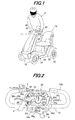
- FIG. 1 is an overall schematic view of an antitheft apparatus for equipment with a prime mover according to an embodiment of the invention, including a small electric vehicle in which the apparatus is installed.
- reference numeral 1 indicates the antitheft apparatus for equipment with a prime mover.
- the explanation will be made by taking a small electric vehicle as an example of the equipment.
- the small electric vehicle is assigned by reference numeral 10.
- the vehicle 10 is a relatively small, single-passenger, electric vehicle, precisely an electric wheelchair or electric four-wheel scooter equipped with a body frame 14 supported by four wheels 12 (one of which is not shown in FIG. 1 ), a seat 16 installed on the frame 14 to be taken by the operator (person; user) P, and an operation unit 20 to be manually operated by the operator P.
- the vehicle 10 is a moving object that moves at extremely low speed, i.e., at a human walking speed, and is suitable for the elderly.
- An electric motor (prime mover) 22 for driving the wheels 12 (specifically rear wheels) and a battery 24 for supplying operating power to the motor 22 are installed under the seat 16.
- the motor 22 comprises a DC brushless motor.
- FIG. 2 is a front view of the operation unit 20 of the vehicle 10 shown in FIG. 1 .
- the operation unit 20 comprises a loop-shaped handle 20b laterally projecting, as curving, from a dashboard 20a, two drive levers 20c that laterally project and allow the operator P to input a moving/stopping instruction, a speed setting knob 20d that allows the operator P to set a desired travel speed within a range starting continuously from 1 km/h up to 6 km/h, forward/reverse switches 20e that allow the operator P to input a traveling direction instruction between forward and reverse travels, a horn switch 20f that allows the operator P to sound a horn (not shown), a power switch 20g that allows the operator P to connect/disconnect power from the battery 24 to the motor 22, and other components.
- Two drive switches 20h are installed near the drive levers 20c.
- the drive switch 20h produces an ON signal when one of the drive levers 20c is manipulated by the operator P to drive and stops outputting the ON signal when manipulated by the operator P to stop.
- a speed setting knob sensor 20i is installed near the knob 20d and produces an output or signal (speed instruction) corresponding to the desired travel speed set by the operator P through the speed setting knob 20d.
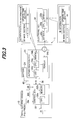
- FIG. 3 is a block diagram showing the configuration of the apparatus 1 of the vehicle 10.
- the apparatus 1 comprises an electronic key 30 that stores ID information (explained later), a control ECU (Electronic Control Unit; prime mover controller) 32 installed in the vehicle 10 for controlling the operation of the motor 22, and an authentication ECU (Electronic Control Unit; authenticator) 34 installed in the vehicle 10 for authenticating the key 30.
- the ECUs 32, 34 are disposed at appropriate locations in the vehicle 10, specifically in the interior of the dashboard 20a of the operation unit 20, as clearly shown in FIG. 2 .
- the control ECU 32 comprises a microcomputer having a CPU 32a, a memory (EEPROM or non-volatile memory) 32b and other components.
- the control ECU 32 is inputted by the operator P with a traveling direction instruction through the forward/reverse switch 20e, a drive instruction through the drive switch 20h, and a speed instruction through the speed setting knob sensor 20i.
- the control ECU 32 controls the operation of the motor 22 and the like in response to those instructions, thereby controlling the operation of the vehicle 10.
- the operator P selects a traveling direction using the forward/reverse switch 20e and sets desired travel speed using the speed setting knob 20d. Then, when the operator P grips or grasps one of (or both of) the drive levers 20c with the handle 20b, the vehicle 10 starts moving at the set speed, and when the operator P releases it, the vehicle 10 stops.
- the authentication ECU 34 similarly to the control ECU 32, comprises a microcomputer having a CPU 34a, a memory (EEPROM or non-volatile memory) 34b for storing authentication ID information, and other components.
- a microcomputer having a CPU 34a, a memory (EEPROM or non-volatile memory) 34b for storing authentication ID information, and other components.
- the authentication ECU 34 further comprises a reader 34c for reading (receiving) the ID information stored in the key 30, and an indicator 34d comprising an LED (Light-Emitting Diode).
- the so-configured authentication ECU 34 is connected to the control ECU 32 through a communication line 36.
- a start enable signal which will be explained later, is transmitted from the authentication ECU 34 to the control ECU 32 through the communication line 36.
- the ECUs 32, 34 are connected to the battery 24 through a power line 40 to be supplied with operating power from the battery 24.
- the key 30 comprises a CPU 30a, a memory 30b for storing the ID information, and an antenna 30c for transmitting the ID information to the reader 34c by short-distance wireless communication (RFID: Radio Frequency Identification).
- RFID Radio Frequency Identification
- the key 30 is made of resin and houses the CPU 30a and other components in its interior.
- the key 30 has a card shape of business card size to be portable. A plurality of keys 30 are prepared to have different ID information for multiple operators P.
- the ID information stored in the key 30 includes data (information) contained in an ID main section and that contained in an updated time section.
- the ID main section contains identification data (operator ID) for identifying the operator P who carries the key 30, identification data (product ID) for identifying the model, product number, etc., of the vehicle 10 (indicated by asterisks in the drawing).
- the updated time section contains information on the number of times the key 30 was updated or reissued, (i.e., key update number of times).
- the key update number of times is the number of times the manufacturer reissued the key 30 in response to request by the operator (owner).
- a value of "00" is contained in the updated time section of a first-issued electronic key 30, "01” in that of a second-issued (first-reissued) key 30, "02” in that of a third-issued (second-reissued) key 30, and so on.
- the authentication ID information stored in the memory 34b of the authentication ECU 34 also includes data (information) contained in an ID main section and updated time section, as shown in FIG. 3 .
- the ID main section contains identification data (operator ID) for identifying the operator P and identification data (product ID) for identifying the model, product number, etc., of the vehicle 10.
- the key 30 Upon receipt of the radio wave from the reader 34c, the key 30 generates power by electromagnetic induction of a built-in coil (not shown), thereby activating the CPU 30a.
- the key 30 is not equipped with a battery or other internal power supply source but is supplied with operating power induced by the radio wave from the reader 34c.
- the key 30 When supplied with power, the key 30 outputs the ID information stored in the memory 30b to the reader 34c through the antenna 30c.
- the authentication ECU 34 acquires the ID information from the key 30 and determines whether the acquired ID information corresponds with the authentication ID information stored in the memory 34b (i.e., the authentication operation is conducted).
- the authentication ECU 34 determines that the key 30 brought close to the reader 34c is an authorized key for the vehicle 10 and sends the start enable signal to the control ECU 32. As a result, the control ECU 32 makes the motor 22 ready for start. Under this condition, when the power switch 20g is made ON, power is supplied from the battery 24 to the motor 22, and when the operator P grasps the drive lever 20c, the motor 22 is driven thereby.
- the authentication ECU 34 determines that the key 30 is not an authorized key and hence, does not send the start enable signal to the control ECU 32. Therefore, even when the power switch 20g is turned ON, power is not supplied from the battery 24 to the motor 22 and even if the operator grasps the drive lever 20c, the motor 22 is not driven.
- the apparatus 1 is configured such that, when the ID information of the key 30 corresponds with the authentication ID information, the authentication ECU 34 enables or allows the motor 22 to start, while, when the two data of ID information do not correspond with each other, it does not enable or allow the motor 22 to start, thereby preventing theft of the vehicle 10.
- the apparatus 1 is characterized in that the updated time section of the ID information contains the information on the number of time the key 30 was updated as explained, and when an updated or reissued key 30 is manipulated as shown in FIG. 4 , the authentication ECU 34 updates the authentication ID information therein so as to correspond with the new ID information of the reissued key 30.
- the authentication ECU 34 updates the authentication ID information therein so as to correspond with the new ID information of the reissued key 30.
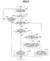
- FIG. 5 is a flowchart showing the operation of the apparatus 1.
- the illustrated program is executed only once upon activation of the authentication ECU 34.
- the authentication ECU 34 is supplied with power from the battery 24 and activated.
- the program begins at S10, in which a key-reading standby mode (i.e., a waiting condition for reading information stored in the key 30) is established.
- the program proceeds to S12, in which it is determined whether the key 30 is manipulated, i.e., is brought close to the reader 34c.
- the program proceeds to S14, in which it is determined whether information in the ID main section of the key 30 and that of the authentication ECU 34 correspond with each other. Specifically, as mentioned above, upon the manipulation of the key 30, the data of the ID information of the key 30 is acquired and it is determined whether the data (information) in the ID main section of the acquired ID information corresponds with that of the authentication ID information of the vehicle 10.
- the program proceeds to S20, in which the number (of times) in the updated time section of the key 30 is compared with that of the authentication ECU 34. Specifically, it is determined whether the number (of times) in the updated time section of the key 30 is greater than that of the authentication ECU 34.
- the program proceeds to S22, in which the number (of times) in the updated time section of the authentication ECU 34 is updated (rewritten). Specifically, the value is updated so as to correspond with (to be equal to) the value in the updated time section of the key 30.
- the affirmative result in S20 means it is the first time that the ID information of a reissued key 30 is read by the authentication ECU 34. Therefore, the authentication ID information is updated so as to correspond with the ID information of the key 30.
- the program proceeds to S18, in which the authentication is verified.
- the ID information of the reissued key 30 when the ID information of the reissued key 30 is read for the first time, the ID information of the key 30 and the authentication ID information of the vehicle 10 does not wholly correspond with each other. However, since the authentication ID information is updated in the next step so as to correspond with the ID information of the key 30, it can be regarded as verified without going through the authentication operation again.
- the negative result in S20 means that the ID information of an old key 30 is read after the ID information of the reissued key 30 has been read.
- the ID main sections correspond with each other but the two data of the whole ID information does not correspond, so that the authentication is not verified.
- the old key 30 could be a lost key 30 or a copy of the old key 30 kept by a former owner (operator), for example, and as shown in FIG. 4 , the old key 30 is no longer verified as an authorized key.
- the program proceeds to S26, in which it is determined whether a predetermined time period (e.g., 30 seconds) has elapsed since the authentication ECU 34 was activated.
- a predetermined time period e.g. 30 seconds
- the embodiment is configured to have an apparatus (1) and method for preventing theft of equipment (electric vehicle 10) having a prime mover (electric motor 22), an prime mover controller (control ECU 32) that controls operation of the prime mover, and an authenticator (authentication ECU 34) that acquires ID information from an electronic key (30) when the key is brought close thereto by an operator (P; S10 ⁇ S12), determines whether the acquired ID information corresponds with authentication ID information (S14 ⁇ S16), and permits the prime mover controller to start the prime mover when the acquired ID information is determined to correspond with the authentication ID information (S 18), characterized in that: the ID information includes data indicating a number of times the key is updated; and the authenticator determines whether the number of times indicated in the data is greater than that in the authentication ID information when the key is brought close thereto by the operator (S20), and when the number of times indicated in the data is greater than that in the authentication ID information, updates the authentication ID information such that the number of times in the authentication ID information is equal to the number of
- the equipment side determines whether the manipulated key is an updated or reissued key based on the ID information acquired from the key and when the result is Yes, the authentication ID information of the equipment is updated so as to correspond with the ID information of the key.
- the authentication ID information of the equipment is updated so as to correspond with the ID information of the key.
- the key update number of times in the ID information of the key is less than that in the authentication ID information of the equipment, it means that the key is an old key, so that the authentication ID information of the equipment is not updated. Consequently the authentication is not verified, thereby preventing theft of the equipment by the old key.
- the authenticator updates the authentication ID information if data other than the number of times in the ID information of the key corresponds with that in the authentication ID information when the number of times indicated in the data is greater than that in the authentication ID information (S 14, S16, S20,S22).
- the equipment side it is reliably determined by the equipment side whether the manipulated key is an updated or reissued key based on the ID information acquired from the key and based thereon, the authentication ID information of the equipment is updated. With this, it becomes possible to reliably update the authentication ID information of the equipment.
- the equipment comprises an electric vehicle (10), and the prime mover comprises an electric motor (22).
- the foregoing embodiment is explained taking the small electric vehicle having the electric motor as an example of the equipment, it may be an outboard motor having an internal combustion engine, or a machine which does not move with power from a built-in prime mover, e.g., an engine generator.
- an apparatus for preventing theft of equipment having a prime mover, an prime mover controller, and an authenticator that acquires ID information from an electronic key when the key is brought close thereto by an operator (S10 ⁇ S12), and permits the prime mover controller to start the prime mover when the acquired ID information is determined to correspond with authentication ID information (S14 ⁇ S18), data indicating a number of times the key is updated is included in the ID information, and the authenticator determines whether the number of times indicated in the data is greater than that in the authentication ID information (S20), and when the number of times indicated in the data is greater than that in the authentication ID information, updates the authentication ID information such that it is equal to the number of times indicated in the data (S22), thereby enabling to easily update authentication ID information of the equipment.
Landscapes
- Engineering & Computer Science (AREA)
- Mechanical Engineering (AREA)
- Lock And Its Accessories (AREA)
- Automatic Cycles, And Cycles In General (AREA)
- Burglar Alarm Systems (AREA)
Abstract
Description
- This invention relates to an antitheft apparatus for equipment with a prime mover.
- Conventionally, an antitheft apparatus (so-called an "immobilizer") for equipment like a vehicle having a prime mover is known which, when an electronic key storing ID information is manipulated by the operator, sends the ID information to an immobilizer controller to verify it with authentication ID information, and only when the authentication is verified (the ID information is valid), allows the prime mover to be started with the electronic key, thereby preventing theft, as taught, for example, by Japanese Laid-Open Patent Application No.
2007-90908 - In the above configuration, when the electronic key is lost, in order to prevent theft by the lost key, it is necessary to prepare another electronic key having new ID information and update authentication ID information stored in the equipment so as to correspond with the new ID information. Also, when the equipment is sold to a new owner (operator), since the former owner might keep a copy of the electronic key, the new owner needs to prepare an electronic key having new ID information and update authentication ID information of the equipment accordingly.
- In this case, it is not so difficult to prepare an electronic key having new ID information because it suffices if the owner only requests the manufacturer to reissue an electronic key. However, as for the update of authentication ID information of the equipment, a service technician of the manufacturer needs to bring an updating device close to the equipment to update the information, or the owner needs to send the equipment itself to the manufacturer. Hence, it is bothersome.
- An object of this invention is therefore to overcome the aforesaid problem by providing an antitheft apparatus for equipment with a prime mover that, when, for instance, an electronic key was lost or the equipment was sold to a new owner, enables to easily update authentication ID information of the equipment.
- In order to achieve the object, this invention provides in its first aspect an apparatus for preventing theft of equipment having a prime mover, an prime mover controller that controls operation of the prime mover, and an authenticator that acquires ID information from an electronic key when the key is brought close thereto by an operator, determines whether the acquired ID information corresponds with authentication ID information, and permits the prime mover controller to start the prime mover when the acquired ID information is determined to correspond with the authentication ID information, characterized in that: the ID information includes data indicating a number of times the key is updated; and the authenticator determines whether the number of times indicated in the data is greater than that in the authentication ID information when the key is brought close thereto by the operator, and when the number of times indicated in the data is greater than that in the authentication ID information, updates the authentication ID information such that the number of times in the authentication ID information is equal to the number of times indicated in the data.
- In order to achieve the object, this invention provides in its second aspect a method for preventing theft of equipment having a prime mover, an prime mover controller that controls operation of the prime mover, and an authentication comprising the steps of acquiring ID information from an electronic key when the key is brought close thereto by an operator, determining whether the acquired ID information corresponds with authentication ID information, and permitting the prime mover controller to start the prime mover when the acquired ID information is determined to correspond with the authentication ID information, characterized by the steps of: including data indicating a number of times the key is updated in the ID information; and determining whether the number of times indicated in the data is greater than that in the authentication ID information when the key is brought close thereto by the operator, and when the number of times indicated in the data is greater than that in the authentication ID information, updating the authentication ID information such that the number of times in the authentication ID information is equal to the number of times indicated in the data.
- The above and other objects and advantages of the invention will be more apparent from the following description and drawings in which:
-
FIG. 1 is an overall schematic view of an antitheft apparatus for equipment with a prime mover according to an embodiment of the invention, including a small electric vehicle in which the apparatus is installed; -
FIG. 2 is a front view of a control panel of the vehicle shown inFIG. 1 ; -
FIG. 3 is a block diagram showing the configuration of the apparatus shown inFIG. 1 ; -
FIG. 4 is a block diagram similar toFIG. 3 , but showing the configuration of the apparatus shown inFIG. 1 ; and -
FIG. 5 is a flowchart showing the operation of the apparatus shown inFIG. 1 . - An antitheft apparatus for equipment with a prime mover according to embodiments of the invention will now be explained with reference to the attached drawings.
-
FIG. 1 is an overall schematic view of an antitheft apparatus for equipment with a prime mover according to an embodiment of the invention, including a small electric vehicle in which the apparatus is installed. - In
FIG. 1 ,reference numeral 1 indicates the antitheft apparatus for equipment with a prime mover. In the following, the explanation will be made by taking a small electric vehicle as an example of the equipment. - The small electric vehicle is assigned by
reference numeral 10. Thevehicle 10 is a relatively small, single-passenger, electric vehicle, precisely an electric wheelchair or electric four-wheel scooter equipped with abody frame 14 supported by four wheels 12 (one of which is not shown inFIG. 1 ), aseat 16 installed on theframe 14 to be taken by the operator (person; user) P, and anoperation unit 20 to be manually operated by the operator P. Thevehicle 10 is a moving object that moves at extremely low speed, i.e., at a human walking speed, and is suitable for the elderly. - An electric motor (prime mover) 22 for driving the wheels 12 (specifically rear wheels) and a
battery 24 for supplying operating power to themotor 22 are installed under theseat 16. Themotor 22 comprises a DC brushless motor. -
FIG. 2 is a front view of theoperation unit 20 of thevehicle 10 shown inFIG. 1 . - As shown in
FIG. 2 , theoperation unit 20 comprises a loop-shaped handle 20b laterally projecting, as curving, from adashboard 20a, two drive levers 20c that laterally project and allow the operator P to input a moving/stopping instruction, aspeed setting knob 20d that allows the operator P to set a desired travel speed within a range starting continuously from 1 km/h up to 6 km/h, forward/reverse switches 20e that allow the operator P to input a traveling direction instruction between forward and reverse travels, ahorn switch 20f that allows the operator P to sound a horn (not shown), apower switch 20g that allows the operator P to connect/disconnect power from thebattery 24 to themotor 22, and other components. - Two
drive switches 20h are installed near thedrive levers 20c. Thedrive switch 20h produces an ON signal when one of thedrive levers 20c is manipulated by the operator P to drive and stops outputting the ON signal when manipulated by the operator P to stop. A speedsetting knob sensor 20i is installed near theknob 20d and produces an output or signal (speed instruction) corresponding to the desired travel speed set by the operator P through thespeed setting knob 20d. - Details of the
vehicle 10 are described in Japanese Laid-Open Patent Application No.2007-112363 -
FIG. 3 is a block diagram showing the configuration of theapparatus 1 of thevehicle 10. - The
apparatus 1 comprises anelectronic key 30 that stores ID information (explained later), a control ECU (Electronic Control Unit; prime mover controller) 32 installed in thevehicle 10 for controlling the operation of themotor 22, and an authentication ECU (Electronic Control Unit; authenticator) 34 installed in thevehicle 10 for authenticating thekey 30. TheECUs vehicle 10, specifically in the interior of thedashboard 20a of theoperation unit 20, as clearly shown inFIG. 2 . - The
control ECU 32 comprises a microcomputer having aCPU 32a, a memory (EEPROM or non-volatile memory) 32b and other components. Thecontrol ECU 32 is inputted by the operator P with a traveling direction instruction through the forward/reverse switch 20e, a drive instruction through thedrive switch 20h, and a speed instruction through the speedsetting knob sensor 20i. Thecontrol ECU 32 controls the operation of themotor 22 and the like in response to those instructions, thereby controlling the operation of thevehicle 10. - Specifically, the operator P selects a traveling direction using the forward/
reverse switch 20e and sets desired travel speed using thespeed setting knob 20d. Then, when the operator P grips or grasps one of (or both of) the drive levers 20c with thehandle 20b, thevehicle 10 starts moving at the set speed, and when the operator P releases it, thevehicle 10 stops. - The
authentication ECU 34, similarly to thecontrol ECU 32, comprises a microcomputer having aCPU 34a, a memory (EEPROM or non-volatile memory) 34b for storing authentication ID information, and other components. - The
authentication ECU 34 further comprises areader 34c for reading (receiving) the ID information stored in thekey 30, and anindicator 34d comprising an LED (Light-Emitting Diode). - The so-
configured authentication ECU 34 is connected to thecontrol ECU 32 through acommunication line 36. A start enable signal, which will be explained later, is transmitted from theauthentication ECU 34 to thecontrol ECU 32 through thecommunication line 36. TheECUs battery 24 through apower line 40 to be supplied with operating power from thebattery 24. - The
key 30 comprises aCPU 30a, amemory 30b for storing the ID information, and anantenna 30c for transmitting the ID information to thereader 34c by short-distance wireless communication (RFID: Radio Frequency Identification). Thekey 30 is made of resin and houses theCPU 30a and other components in its interior. The key 30 has a card shape of business card size to be portable. A plurality ofkeys 30 are prepared to have different ID information for multiple operators P. - As illustrated, the ID information stored in the
key 30 includes data (information) contained in an ID main section and that contained in an updated time section. The ID main section contains identification data (operator ID) for identifying the operator P who carries thekey 30, identification data (product ID) for identifying the model, product number, etc., of the vehicle 10 (indicated by asterisks in the drawing). The updated time section contains information on the number of times thekey 30 was updated or reissued, (i.e., key update number of times). The key update number of times is the number of times the manufacturer reissued thekey 30 in response to request by the operator (owner). More specifically, a value of "00" is contained in the updated time section of a first-issuedelectronic key 30, "01" in that of a second-issued (first-reissued)key 30, "02" in that of a third-issued (second-reissued)key 30, and so on. - The authentication ID information stored in the
memory 34b of theauthentication ECU 34 also includes data (information) contained in an ID main section and updated time section, as shown inFIG. 3 . Similarly to the case of thekey 30, the ID main section contains identification data (operator ID) for identifying the operator P and identification data (product ID) for identifying the model, product number, etc., of thevehicle 10. When thevehicle 10 is produced, a value of "00" representing the initial status is entered in the updated time section. - There now follows an explanation of the authentication operation between the key 30 and
authentication ECU 34. When thekey 30 is brought close to and held over thereader 34c by the operator P with theauthentication ECU 34 being supplied with operating power from thebattery 24, thereader 34c can read and output (transmit) radio wave to the key 3 0. - Upon receipt of the radio wave from the
reader 34c, thekey 30 generates power by electromagnetic induction of a built-in coil (not shown), thereby activating theCPU 30a. In other words, thekey 30 is not equipped with a battery or other internal power supply source but is supplied with operating power induced by the radio wave from thereader 34c. - When supplied with power, the key 30 outputs the ID information stored in the
memory 30b to thereader 34c through theantenna 30c. Theauthentication ECU 34 acquires the ID information from the key 30 and determines whether the acquired ID information corresponds with the authentication ID information stored in thememory 34b (i.e., the authentication operation is conducted). - When the above two data of ID information correspond with each other, the
authentication ECU 34 determines that the key 30 brought close to thereader 34c is an authorized key for thevehicle 10 and sends the start enable signal to thecontrol ECU 32. As a result, thecontrol ECU 32 makes themotor 22 ready for start. Under this condition, when thepower switch 20g is made ON, power is supplied from thebattery 24 to themotor 22, and when the operator P grasps thedrive lever 20c, themotor 22 is driven thereby. - In contrast, when the two data of ID information do not correspond with each other, the
authentication ECU 34 determines that the key 30 is not an authorized key and hence, does not send the start enable signal to thecontrol ECU 32. Therefore, even when thepower switch 20g is turned ON, power is not supplied from thebattery 24 to themotor 22 and even if the operator grasps thedrive lever 20c, themotor 22 is not driven. - Thus, the
apparatus 1 is configured such that, when the ID information of the key 30 corresponds with the authentication ID information, theauthentication ECU 34 enables or allows themotor 22 to start, while, when the two data of ID information do not correspond with each other, it does not enable or allow themotor 22 to start, thereby preventing theft of thevehicle 10. - The
apparatus 1 according to this embodiment is characterized in that the updated time section of the ID information contains the information on the number of time the key 30 was updated as explained, and when an updated or reissued key 30 is manipulated as shown inFIG. 4 , theauthentication ECU 34 updates the authentication ID information therein so as to correspond with the new ID information of the reissuedkey 30. In the following, more details of the operation of theapparatus 1 will be explained. -
FIG. 5 is a flowchart showing the operation of theapparatus 1. The illustrated program is executed only once upon activation of theauthentication ECU 34. When an appropriate switch is made ON, theauthentication ECU 34 is supplied with power from thebattery 24 and activated. - The program begins at S10, in which a key-reading standby mode (i.e., a waiting condition for reading information stored in the key 30) is established. The program proceeds to S12, in which it is determined whether the key 30 is manipulated, i.e., is brought close to the
reader 34c. - When the result in S12 is affirmative, the program proceeds to S14, in which it is determined whether information in the ID main section of the key 30 and that of the
authentication ECU 34 correspond with each other. Specifically, as mentioned above, upon the manipulation of the key 30, the data of the ID information of the key 30 is acquired and it is determined whether the data (information) in the ID main section of the acquired ID information corresponds with that of the authentication ID information of thevehicle 10. - When the result in
S 14 is affirmative, the program proceeds to S16, in which it is determined whether the number (of times) in the updated time section of the ID information of the key 30 corresponds with that of the authentication ID information of thevehicle 10. - When the result in
S 16 is affirmative, since it means that the data of the ID information of the key 30 and that of the authentication ID information of thevehicle 10 wholly correspond with each other, the program proceeds to S18, in which the authentication is verified, i.e., the start enable signal is transmitted to the control ECU 32 (i.e., theauthenticator ECU 34 permits the prime mover controller to start the prime mover when the acquired ID information is determined to correspond with the authentication ID information). Then the program is terminated and theauthentication ECU 34 is made OFF. - On the other hand, when the result in S16 is negative, the program proceeds to S20, in which the number (of times) in the updated time section of the key 30 is compared with that of the
authentication ECU 34. Specifically, it is determined whether the number (of times) in the updated time section of the key 30 is greater than that of theauthentication ECU 34. - When the result in S20 is affirmative, the program proceeds to S22, in which the number (of times) in the updated time section of the
authentication ECU 34 is updated (rewritten). Specifically, the value is updated so as to correspond with (to be equal to) the value in the updated time section of the key 30. - More specifically, the affirmative result in S20 means it is the first time that the ID information of a reissued key 30 is read by the
authentication ECU 34. Therefore, the authentication ID information is updated so as to correspond with the ID information of the key 30. Following S22, the program proceeds to S18, in which the authentication is verified. - It should be noted that, when the ID information of the reissued key 30 is read for the first time, the ID information of the key 30 and the authentication ID information of the
vehicle 10 does not wholly correspond with each other. However, since the authentication ID information is updated in the next step so as to correspond with the ID information of the key 30, it can be regarded as verified without going through the authentication operation again. - When the result in S20 is negative, the program proceeds to S24, in which the authentication is not verified, i.e., the start enable signal is not transmitted to the
control ECU 32. Then the program is terminated and theauthentication ECU 34 is made OFF. - More specifically, the negative result in S20 means that the ID information of an old key 30 is read after the ID information of the reissued key 30 has been read. In this case, the ID main sections correspond with each other but the two data of the whole ID information does not correspond, so that the authentication is not verified. The old key 30 could be a lost key 30 or a copy of the old key 30 kept by a former owner (operator), for example, and as shown in
FIG. 4 , the old key 30 is no longer verified as an authorized key. - When the result in
S 12 is negative, the program proceeds to S26, in which it is determined whether a predetermined time period (e.g., 30 seconds) has elapsed since theauthentication ECU 34 was activated. When the result is No, the program returns to S10, while, when the result is Yes, the program is terminated and theauthentication ECU 34 is made OFF. - As stated above, the embodiment is configured to have an apparatus (1) and method for preventing theft of equipment (electric vehicle 10) having a prime mover (electric motor 22), an prime mover controller (control ECU 32) that controls operation of the prime mover, and an authenticator (authentication ECU 34) that acquires ID information from an electronic key (30) when the key is brought close thereto by an operator (P; S10 ― S12), determines whether the acquired ID information corresponds with authentication ID information (S14 ― S16), and permits the prime mover controller to start the prime mover when the acquired ID information is determined to correspond with the authentication ID information (S 18), characterized in that: the ID information includes data indicating a number of times the key is updated; and the authenticator determines whether the number of times indicated in the data is greater than that in the authentication ID information when the key is brought close thereto by the operator (S20), and when the number of times indicated in the data is greater than that in the authentication ID information, updates the authentication ID information such that the number of times in the authentication ID information is equal to the number of times indicated in the data (S22).
- Specifically, it is determined by the equipment side whether the manipulated key is an updated or reissued key based on the ID information acquired from the key and when the result is Yes, the authentication ID information of the equipment is updated so as to correspond with the ID information of the key. With this, it becomes possible to update the authentication ID information of the equipment easily. As a result, even when the electronic key was lost or the equipment was sold to a new owner, it becomes possible to easily deal with it only by preparing a reissued key with new ID information.
- Further, when it is determined that the key update number of times in the ID information of the key is less than that in the authentication ID information of the equipment, it means that the key is an old key, so that the authentication ID information of the equipment is not updated. Consequently the authentication is not verified, thereby preventing theft of the equipment by the old key.
- In the apparatus, the authenticator updates the authentication ID information if data other than the number of times in the ID information of the key corresponds with that in the authentication ID information when the number of times indicated in the data is greater than that in the authentication ID information (
S 14, S16, S20,S22). - Specifically, it is reliably determined by the equipment side whether the manipulated key is an updated or reissued key based on the ID information acquired from the key and based thereon, the authentication ID information of the equipment is updated. With this, it becomes possible to reliably update the authentication ID information of the equipment.
- In the apparatus and method, the equipment comprises an electric vehicle (10), and the prime mover comprises an electric motor (22).
- It should be noted that, although the foregoing embodiment is explained taking the small electric vehicle having the electric motor as an example of the equipment, it may be an outboard motor having an internal combustion engine, or a machine which does not move with power from a built-in prime mover, e.g., an engine generator.
- In an apparatus for preventing theft of equipment having a prime mover, an prime mover controller, and an authenticator that acquires ID information from an electronic key when the key is brought close thereto by an operator (S10 ― S12), and permits the prime mover controller to start the prime mover when the acquired ID information is determined to correspond with authentication ID information (S14 ― S18), data indicating a number of times the key is updated is included in the ID information, and the authenticator determines whether the number of times indicated in the data is greater than that in the authentication ID information (S20), and when the number of times indicated in the data is greater than that in the authentication ID information, updates the authentication ID information such that it is equal to the number of times indicated in the data (S22), thereby enabling to easily update authentication ID information of the equipment.
Claims (8)
- An apparatus (1) for preventing theft of equipment (10) having a prime mover (22), an prime mover controller (32) that controls operation of the prime mover, and an authenticator (34) that acquires ID information from an electronic key (30) when the key is brought close thereto by an operator (P; S10 ― S12), determines whether the acquired ID information corresponds with authentication ID information (S14 ― S16), and permits the prime mover controller to start the prime mover when the acquired ID information is determined to correspond with the authentication ID information (S 18),
characterized in that:the ID information includes data indicating a number of times the key is updated; andthe authenticator determines whether the number of times indicated in the data is greater than that in the authentication ID information when the key is brought close thereto by the operator (S20), and when the number of times indicated in the data is greater than that in the authentication ID information, updates the authentication ID information such that the number of times in the authentication ID information is equal to the number of times indicated in the data (S22). - The apparatus according to claim 1, wherein the authenticator updates the authentication ID information if data other than the number of times in the ID information of the key corresponds with that in the authentication ID information when the number of times indicated in the data is greater than that in the authentication ID information (S14, S16, S20, S22).
- The apparatus according to claim 1 or 2, wherein the equipment comprises an electric vehicle (10).
- The apparatus according to claim 3, wherein the prime mover comprises an electric motor (22).
- A method for preventing theft of equipment (10) having a prime mover (22), an prime mover controller (32) that controls operation of the prime mover, and an authentication (34) comprising the steps of acquiring ID information from an electronic key (30) when the key is brought close thereto by an operator (P; S10 ― S12), determining whether the acquired ID information corresponds with authentication ID information (S14 ― S16), and permitting the prime mover controller to start the prime mover when the acquired ID information is determined to correspond with the authentication ID information (S 18),
characterized by the steps of:including data indicating a number of times the key is updated in the ID information; anddetermining whether the number of times indicated in the data is greater than that in the authentication ID information when the key is brought close thereto by the operator (S20), and when the number of times indicated in the data is greater than that in the authentication ID information, updating the authentication ID information such that the number of times in the authentication ID information is equal to the number of times indicated in the data (S22). - The method according to claim 5, wherein the step of updating updates the authentication ID information if data other than the number of times in the ID information of the key corresponds with that in the authentication ID information when the number of times indicated in the data is greater than that in the authentication ID information (S 14, S16, S20, S22).
- The method according to claim 5 or 6, wherein the equipment comprises an electric vehicle (10).
- The method according to claim 7, wherein the prime mover comprises an electric motor (22).
Applications Claiming Priority (1)
| Application Number | Priority Date | Filing Date | Title |
|---|---|---|---|
| JP2009279932A JP5130279B2 (en) | 2009-12-09 | 2009-12-09 | Anti-theft device for drive source equipment |
Publications (2)
| Publication Number | Publication Date |
|---|---|
| EP2332790A1 true EP2332790A1 (en) | 2011-06-15 |
| EP2332790B1 EP2332790B1 (en) | 2011-11-23 |
Family
ID=43651553
Family Applications (1)
| Application Number | Title | Priority Date | Filing Date |
|---|---|---|---|
| EP20100194125 Not-in-force EP2332790B1 (en) | 2009-12-09 | 2010-12-08 | Antitheft apparatus for equipment with prime mover |
Country Status (5)
| Country | Link |
|---|---|
| US (1) | US8305202B2 (en) |
| EP (1) | EP2332790B1 (en) |
| JP (1) | JP5130279B2 (en) |
| CN (1) | CN102094552B (en) |
| AT (1) | ATE534558T1 (en) |
Cited By (3)
| Publication number | Priority date | Publication date | Assignee | Title |
|---|---|---|---|---|
| FR3030830A1 (en) * | 2014-12-23 | 2016-06-24 | Valeo Comfort & Driving Assistance | METHOD OF SECURING ACCESS TO AT LEAST ONE FUNCTIONALITY OF A MOTOR VEHICLE BY A MOBILE TERMINAL |
| WO2016132078A1 (en) * | 2015-02-18 | 2016-08-25 | Valeo Comfort And Driving Assistance | Method of securing access to at least one functionality of a motor vehicle by a mobile terminal |
| CN107010140A (en) * | 2017-03-16 | 2017-08-04 | 南京壹佰克智能科技有限公司 | Electric bicycle and the theft preventing method for electric bicycle |
Families Citing this family (2)
| Publication number | Priority date | Publication date | Assignee | Title |
|---|---|---|---|---|
| CN112669491B (en) * | 2020-12-16 | 2022-12-09 | 广州橙行智动汽车科技有限公司 | A method and device for distribution and management of vehicle digital keys |
| CN113911066B (en) * | 2021-10-15 | 2022-11-29 | 岚图汽车科技有限公司 | Electric automobile anti-theft control method and related equipment |
Citations (5)
| Publication number | Priority date | Publication date | Assignee | Title |
|---|---|---|---|---|
| US5513105A (en) * | 1994-05-31 | 1996-04-30 | Krones; Daniel K. | Vehicle security system |
| US6204570B1 (en) * | 1997-05-21 | 2001-03-20 | Siemens Aktiengesellschaft | Method for initializing an anti-theft system of a motor vehicle |
| US6683391B1 (en) * | 1999-09-03 | 2004-01-27 | Kabushiki Kaisha Moric | Method of preventing car thefts |
| JP2007090908A (en) | 2005-09-26 | 2007-04-12 | Kubota Corp | Anti-theft device for construction equipment |
| JP2007112363A (en) | 2005-10-21 | 2007-05-10 | Honda Motor Co Ltd | Rear suspension system for small electric vehicles |
Family Cites Families (13)
| Publication number | Priority date | Publication date | Assignee | Title |
|---|---|---|---|---|
| JPH10184121A (en) * | 1996-12-27 | 1998-07-14 | Mitsuba Corp | Vehicular antitheft method |
| KR100307665B1 (en) * | 1997-05-23 | 2001-10-19 | 하재홍 | Lock and key system employing an id code |
| DE19917817A1 (en) * | 1999-04-20 | 2000-10-26 | Siemens Ag | Motor vehicle electronic monitoring system esp. anti-theft device |
| JP4193922B2 (en) * | 1999-09-03 | 2008-12-10 | ヤマハモーターエレクトロニクス株式会社 | Vehicle theft prevention method and apparatus |
| JP2006118205A (en) * | 2004-10-21 | 2006-05-11 | Sanyo Electric Co Ltd | Keyless entry system, transmitter and receiver |
| JP4568620B2 (en) * | 2005-02-24 | 2010-10-27 | 本田技研工業株式会社 | Electronic key system for vehicle and vehicle |
| JP2006295872A (en) * | 2005-03-18 | 2006-10-26 | Matsushita Electric Ind Co Ltd | Device unique key generation method, confidential information LSI having a confidential information processing function using the same, host device having the same, recording medium with an authentication function used therefor, and portable terminal with a recording medium having an authentication function |
| JP4594351B2 (en) * | 2007-05-21 | 2010-12-08 | 株式会社ユピテル | Equipment control system |
| US20090138714A1 (en) * | 2007-11-26 | 2009-05-28 | Kabushiki Kaisha Toshiba | Communication apparatus, key server, management server, communication server, content distribution system, communication method, and recording medium |
| JP4610647B2 (en) * | 2008-02-28 | 2011-01-12 | 株式会社コナミデジタルエンタテインメント | NETWORK GAME SYSTEM, NETWORK GAME PROGRAM, NETWORK GAME DEVICE, AND NETWORK GAME CONTROL METHOD |
| JP5138486B2 (en) * | 2008-07-10 | 2013-02-06 | 本田技研工業株式会社 | Device anti-theft device |
| JP5130278B2 (en) * | 2009-12-09 | 2013-01-30 | 本田技研工業株式会社 | Anti-theft device for drive source equipment |
| JP5227943B2 (en) * | 2009-12-09 | 2013-07-03 | 本田技研工業株式会社 | Anti-theft device for drive source equipment |
-
2009
- 2009-12-09 JP JP2009279932A patent/JP5130279B2/en active Active
-
2010
- 2010-11-30 CN CN2010105683444A patent/CN102094552B/en not_active Expired - Fee Related
- 2010-12-06 US US12/961,165 patent/US8305202B2/en active Active
- 2010-12-08 EP EP20100194125 patent/EP2332790B1/en not_active Not-in-force
- 2010-12-08 AT AT10194125T patent/ATE534558T1/en active
Patent Citations (5)
| Publication number | Priority date | Publication date | Assignee | Title |
|---|---|---|---|---|
| US5513105A (en) * | 1994-05-31 | 1996-04-30 | Krones; Daniel K. | Vehicle security system |
| US6204570B1 (en) * | 1997-05-21 | 2001-03-20 | Siemens Aktiengesellschaft | Method for initializing an anti-theft system of a motor vehicle |
| US6683391B1 (en) * | 1999-09-03 | 2004-01-27 | Kabushiki Kaisha Moric | Method of preventing car thefts |
| JP2007090908A (en) | 2005-09-26 | 2007-04-12 | Kubota Corp | Anti-theft device for construction equipment |
| JP2007112363A (en) | 2005-10-21 | 2007-05-10 | Honda Motor Co Ltd | Rear suspension system for small electric vehicles |
Cited By (3)
| Publication number | Priority date | Publication date | Assignee | Title |
|---|---|---|---|---|
| FR3030830A1 (en) * | 2014-12-23 | 2016-06-24 | Valeo Comfort & Driving Assistance | METHOD OF SECURING ACCESS TO AT LEAST ONE FUNCTIONALITY OF A MOTOR VEHICLE BY A MOBILE TERMINAL |
| WO2016132078A1 (en) * | 2015-02-18 | 2016-08-25 | Valeo Comfort And Driving Assistance | Method of securing access to at least one functionality of a motor vehicle by a mobile terminal |
| CN107010140A (en) * | 2017-03-16 | 2017-08-04 | 南京壹佰克智能科技有限公司 | Electric bicycle and the theft preventing method for electric bicycle |
Also Published As
| Publication number | Publication date |
|---|---|
| CN102094552B (en) | 2013-08-21 |
| JP5130279B2 (en) | 2013-01-30 |
| EP2332790B1 (en) | 2011-11-23 |
| CN102094552A (en) | 2011-06-15 |
| JP2011121451A (en) | 2011-06-23 |
| US20110133911A1 (en) | 2011-06-09 |
| US8305202B2 (en) | 2012-11-06 |
| ATE534558T1 (en) | 2011-12-15 |
Similar Documents
| Publication | Publication Date | Title |
|---|---|---|
| EP2332789B1 (en) | Antitheft apparatus for equipment with prime mover | |
| JP4598567B2 (en) | Vehicle anti-theft system | |
| EP2332790B1 (en) | Antitheft apparatus for equipment with prime mover | |
| JP4460946B2 (en) | Operation control device | |
| EP2251837A2 (en) | Portable device and remote control system | |
| US20090033150A1 (en) | Apparatus and method for starting engine of automobile using start-button | |
| CN114312657A (en) | Remote starting method and system of vehicle, storage medium and vehicle | |
| CN109644188B (en) | Method for updating a password for remotely starting a motor vehicle | |
| JP2013121791A (en) | Vehicle remote start device | |
| JP2010019004A (en) | Anti-theft unit of equipment | |
| JP3799961B2 (en) | Electronic key device for vehicle | |
| JP2003127831A (en) | Electronic key device for vehicles | |
| JP6329686B2 (en) | Remote starter for vehicle | |
| JP2003056230A (en) | Electronic key device for vehicles | |
| US8704402B2 (en) | Antitheft apparatus for equipment with prime mover | |
| JP2008050943A (en) | Vehicular wireless control device | |
| JP5144946B2 (en) | Vehicle anti-theft system and vehicle equipped with anti-theft system | |
| JP6612921B2 (en) | Remote starter for vehicle | |
| JP6289537B2 (en) | Remote starter for vehicle | |
| JP2008150016A (en) | Engine start control device and engine start control method | |
| US20240326745A1 (en) | Mobile object setting system and mobile object setting method | |
| JP2013121076A (en) | Communication equipment system | |
| CN119489778A (en) | Vehicle control method, device, vehicle and storage medium | |
| CN118741451A (en) | Mobile body setting system, mobile body setting method and storage medium | |
| JPH10157571A (en) | Immobilizer system for automobile |
Legal Events
| Date | Code | Title | Description |
|---|---|---|---|
| PUAI | Public reference made under article 153(3) epc to a published international application that has entered the european phase |
Free format text: ORIGINAL CODE: 0009012 |
|
| 17P | Request for examination filed |
Effective date: 20101208 |
|
| AK | Designated contracting states |
Kind code of ref document: A1 Designated state(s): AL AT BE BG CH CY CZ DE DK EE ES FI FR GB GR HR HU IE IS IT LI LT LU LV MC MK MT NL NO PL PT RO RS SE SI SK SM TR |
|
| AX | Request for extension of the european patent |
Extension state: BA ME |
|
| GRAP | Despatch of communication of intention to grant a patent |
Free format text: ORIGINAL CODE: EPIDOSNIGR1 |
|
| RIC1 | Information provided on ipc code assigned before grant |
Ipc: B60R 25/04 20060101AFI20110620BHEP |
|
| GRAS | Grant fee paid |
Free format text: ORIGINAL CODE: EPIDOSNIGR3 |
|
| GRAA | (expected) grant |
Free format text: ORIGINAL CODE: 0009210 |
|
| RIN1 | Information on inventor provided before grant (corrected) |
Inventor name: YAMASHITA, KOSEI Inventor name: TAKEDA, MASATO Inventor name: YAMAMURA, MAKOTO Inventor name: MANITA, MASASHI Inventor name: MAEKAWA, YOSHINORI Inventor name: SHINOGI, YOSHIHISA |
|
| AK | Designated contracting states |
Kind code of ref document: B1 Designated state(s): AL AT BE BG CH CY CZ DE DK EE ES FI FR GB GR HR HU IE IS IT LI LT LU LV MC MK MT NL NO PL PT RO RS SE SI SK SM TR |
|
| REG | Reference to a national code |
Ref country code: GB Ref legal event code: FG4D |
|
| REG | Reference to a national code |
Ref country code: CH Ref legal event code: EP |
|
| REG | Reference to a national code |
Ref country code: IE Ref legal event code: FG4D |
|
| REG | Reference to a national code |
Ref country code: DE Ref legal event code: R096 Ref document number: 602010000447 Country of ref document: DE Effective date: 20120216 |
|
| REG | Reference to a national code |
Ref country code: NL Ref legal event code: VDEP Effective date: 20111123 |
|
| LTIE | Lt: invalidation of european patent or patent extension |
Effective date: 20111123 |
|
| PG25 | Lapsed in a contracting state [announced via postgrant information from national office to epo] |
Ref country code: IS Free format text: LAPSE BECAUSE OF FAILURE TO SUBMIT A TRANSLATION OF THE DESCRIPTION OR TO PAY THE FEE WITHIN THE PRESCRIBED TIME-LIMIT Effective date: 20120323 Ref country code: LT Free format text: LAPSE BECAUSE OF FAILURE TO SUBMIT A TRANSLATION OF THE DESCRIPTION OR TO PAY THE FEE WITHIN THE PRESCRIBED TIME-LIMIT Effective date: 20111123 Ref country code: NO Free format text: LAPSE BECAUSE OF FAILURE TO SUBMIT A TRANSLATION OF THE DESCRIPTION OR TO PAY THE FEE WITHIN THE PRESCRIBED TIME-LIMIT Effective date: 20120223 |
|
| PG25 | Lapsed in a contracting state [announced via postgrant information from national office to epo] |
Ref country code: GR Free format text: LAPSE BECAUSE OF FAILURE TO SUBMIT A TRANSLATION OF THE DESCRIPTION OR TO PAY THE FEE WITHIN THE PRESCRIBED TIME-LIMIT Effective date: 20120224 Ref country code: BE Free format text: LAPSE BECAUSE OF FAILURE TO SUBMIT A TRANSLATION OF THE DESCRIPTION OR TO PAY THE FEE WITHIN THE PRESCRIBED TIME-LIMIT Effective date: 20111123 Ref country code: SE Free format text: LAPSE BECAUSE OF FAILURE TO SUBMIT A TRANSLATION OF THE DESCRIPTION OR TO PAY THE FEE WITHIN THE PRESCRIBED TIME-LIMIT Effective date: 20111123 Ref country code: NL Free format text: LAPSE BECAUSE OF FAILURE TO SUBMIT A TRANSLATION OF THE DESCRIPTION OR TO PAY THE FEE WITHIN THE PRESCRIBED TIME-LIMIT Effective date: 20111123 Ref country code: HR Free format text: LAPSE BECAUSE OF FAILURE TO SUBMIT A TRANSLATION OF THE DESCRIPTION OR TO PAY THE FEE WITHIN THE PRESCRIBED TIME-LIMIT Effective date: 20111123 Ref country code: SI Free format text: LAPSE BECAUSE OF FAILURE TO SUBMIT A TRANSLATION OF THE DESCRIPTION OR TO PAY THE FEE WITHIN THE PRESCRIBED TIME-LIMIT Effective date: 20111123 Ref country code: PT Free format text: LAPSE BECAUSE OF FAILURE TO SUBMIT A TRANSLATION OF THE DESCRIPTION OR TO PAY THE FEE WITHIN THE PRESCRIBED TIME-LIMIT Effective date: 20120323 Ref country code: LV Free format text: LAPSE BECAUSE OF FAILURE TO SUBMIT A TRANSLATION OF THE DESCRIPTION OR TO PAY THE FEE WITHIN THE PRESCRIBED TIME-LIMIT Effective date: 20111123 |
|
| PG25 | Lapsed in a contracting state [announced via postgrant information from national office to epo] |
Ref country code: CY Free format text: LAPSE BECAUSE OF FAILURE TO SUBMIT A TRANSLATION OF THE DESCRIPTION OR TO PAY THE FEE WITHIN THE PRESCRIBED TIME-LIMIT Effective date: 20111123 Ref country code: RS Free format text: LAPSE BECAUSE OF FAILURE TO SUBMIT A TRANSLATION OF THE DESCRIPTION OR TO PAY THE FEE WITHIN THE PRESCRIBED TIME-LIMIT Effective date: 20111123 |
|
| PG25 | Lapsed in a contracting state [announced via postgrant information from national office to epo] |
Ref country code: CZ Free format text: LAPSE BECAUSE OF FAILURE TO SUBMIT A TRANSLATION OF THE DESCRIPTION OR TO PAY THE FEE WITHIN THE PRESCRIBED TIME-LIMIT Effective date: 20111123 Ref country code: BG Free format text: LAPSE BECAUSE OF FAILURE TO SUBMIT A TRANSLATION OF THE DESCRIPTION OR TO PAY THE FEE WITHIN THE PRESCRIBED TIME-LIMIT Effective date: 20120223 Ref country code: MC Free format text: LAPSE BECAUSE OF NON-PAYMENT OF DUE FEES Effective date: 20111231 Ref country code: DK Free format text: LAPSE BECAUSE OF FAILURE TO SUBMIT A TRANSLATION OF THE DESCRIPTION OR TO PAY THE FEE WITHIN THE PRESCRIBED TIME-LIMIT Effective date: 20111123 Ref country code: EE Free format text: LAPSE BECAUSE OF FAILURE TO SUBMIT A TRANSLATION OF THE DESCRIPTION OR TO PAY THE FEE WITHIN THE PRESCRIBED TIME-LIMIT Effective date: 20111123 Ref country code: SK Free format text: LAPSE BECAUSE OF FAILURE TO SUBMIT A TRANSLATION OF THE DESCRIPTION OR TO PAY THE FEE WITHIN THE PRESCRIBED TIME-LIMIT Effective date: 20111123 |
|
| PG25 | Lapsed in a contracting state [announced via postgrant information from national office to epo] |
Ref country code: PL Free format text: LAPSE BECAUSE OF FAILURE TO SUBMIT A TRANSLATION OF THE DESCRIPTION OR TO PAY THE FEE WITHIN THE PRESCRIBED TIME-LIMIT Effective date: 20111123 Ref country code: RO Free format text: LAPSE BECAUSE OF FAILURE TO SUBMIT A TRANSLATION OF THE DESCRIPTION OR TO PAY THE FEE WITHIN THE PRESCRIBED TIME-LIMIT Effective date: 20111123 |
|
| REG | Reference to a national code |
Ref country code: AT Ref legal event code: MK05 Ref document number: 534558 Country of ref document: AT Kind code of ref document: T Effective date: 20111123 |
|
| PLBE | No opposition filed within time limit |
Free format text: ORIGINAL CODE: 0009261 |
|
| STAA | Information on the status of an ep patent application or granted ep patent |
Free format text: STATUS: NO OPPOSITION FILED WITHIN TIME LIMIT |
|
| 26N | No opposition filed |
Effective date: 20120824 |
|
| REG | Reference to a national code |
Ref country code: DE Ref legal event code: R097 Ref document number: 602010000447 Country of ref document: DE Effective date: 20120824 |
|
| PG25 | Lapsed in a contracting state [announced via postgrant information from national office to epo] |
Ref country code: AT Free format text: LAPSE BECAUSE OF FAILURE TO SUBMIT A TRANSLATION OF THE DESCRIPTION OR TO PAY THE FEE WITHIN THE PRESCRIBED TIME-LIMIT Effective date: 20111123 |
|
| PG25 | Lapsed in a contracting state [announced via postgrant information from national office to epo] |
Ref country code: ES Free format text: LAPSE BECAUSE OF FAILURE TO SUBMIT A TRANSLATION OF THE DESCRIPTION OR TO PAY THE FEE WITHIN THE PRESCRIBED TIME-LIMIT Effective date: 20120305 |
|
| PG25 | Lapsed in a contracting state [announced via postgrant information from national office to epo] |
Ref country code: FI Free format text: LAPSE BECAUSE OF FAILURE TO SUBMIT A TRANSLATION OF THE DESCRIPTION OR TO PAY THE FEE WITHIN THE PRESCRIBED TIME-LIMIT Effective date: 20111123 |
|
| REG | Reference to a national code |
Ref country code: IE Ref legal event code: MM4A |
|
| PG25 | Lapsed in a contracting state [announced via postgrant information from national office to epo] |
Ref country code: TR Free format text: LAPSE BECAUSE OF FAILURE TO SUBMIT A TRANSLATION OF THE DESCRIPTION OR TO PAY THE FEE WITHIN THE PRESCRIBED TIME-LIMIT Effective date: 20111123 |
|
| PG25 | Lapsed in a contracting state [announced via postgrant information from national office to epo] |
Ref country code: HU Free format text: LAPSE BECAUSE OF FAILURE TO SUBMIT A TRANSLATION OF THE DESCRIPTION OR TO PAY THE FEE WITHIN THE PRESCRIBED TIME-LIMIT Effective date: 20111123 Ref country code: IE Free format text: LAPSE BECAUSE OF NON-PAYMENT OF DUE FEES Effective date: 20121208 |
|
| PG25 | Lapsed in a contracting state [announced via postgrant information from national office to epo] |
Ref country code: AL Free format text: LAPSE BECAUSE OF FAILURE TO SUBMIT A TRANSLATION OF THE DESCRIPTION OR TO PAY THE FEE WITHIN THE PRESCRIBED TIME-LIMIT Effective date: 20111123 Ref country code: MT Free format text: LAPSE BECAUSE OF FAILURE TO SUBMIT A TRANSLATION OF THE DESCRIPTION OR TO PAY THE FEE WITHIN THE PRESCRIBED TIME-LIMIT Effective date: 20111123 |
|
| PG25 | Lapsed in a contracting state [announced via postgrant information from national office to epo] |
Ref country code: SM Free format text: LAPSE BECAUSE OF FAILURE TO SUBMIT A TRANSLATION OF THE DESCRIPTION OR TO PAY THE FEE WITHIN THE PRESCRIBED TIME-LIMIT Effective date: 20111123 Ref country code: LU Free format text: LAPSE BECAUSE OF NON-PAYMENT OF DUE FEES Effective date: 20111208 |
|
| REG | Reference to a national code |
Ref country code: DE Ref legal event code: R084 Ref document number: 602010000447 Country of ref document: DE |
|
| REG | Reference to a national code |
Ref country code: DE Ref legal event code: R084 Ref document number: 602010000447 Country of ref document: DE Effective date: 20140821 |
|
| PG25 | Lapsed in a contracting state [announced via postgrant information from national office to epo] |
Ref country code: MK Free format text: LAPSE BECAUSE OF FAILURE TO SUBMIT A TRANSLATION OF THE DESCRIPTION OR TO PAY THE FEE WITHIN THE PRESCRIBED TIME-LIMIT Effective date: 20111123 |
|
| REG | Reference to a national code |
Ref country code: CH Ref legal event code: PL |
|
| GBPC | Gb: european patent ceased through non-payment of renewal fee |
Effective date: 20141208 |
|
| PG25 | Lapsed in a contracting state [announced via postgrant information from national office to epo] |
Ref country code: CH Free format text: LAPSE BECAUSE OF NON-PAYMENT OF DUE FEES Effective date: 20141231 Ref country code: LI Free format text: LAPSE BECAUSE OF NON-PAYMENT OF DUE FEES Effective date: 20141231 Ref country code: GB Free format text: LAPSE BECAUSE OF NON-PAYMENT OF DUE FEES Effective date: 20141208 |
|
| REG | Reference to a national code |
Ref country code: FR Ref legal event code: PLFP Year of fee payment: 6 |
|
| REG | Reference to a national code |
Ref country code: FR Ref legal event code: PLFP Year of fee payment: 7 |
|
| REG | Reference to a national code |
Ref country code: FR Ref legal event code: PLFP Year of fee payment: 8 |
|
| PGFP | Annual fee paid to national office [announced via postgrant information from national office to epo] |
Ref country code: IT Payment date: 20191209 Year of fee payment: 10 |
|
| PGFP | Annual fee paid to national office [announced via postgrant information from national office to epo] |
Ref country code: DE Payment date: 20201124 Year of fee payment: 11 Ref country code: FR Payment date: 20201112 Year of fee payment: 11 |
|
| PG25 | Lapsed in a contracting state [announced via postgrant information from national office to epo] |
Ref country code: IT Free format text: LAPSE BECAUSE OF NON-PAYMENT OF DUE FEES Effective date: 20201208 |
|
| REG | Reference to a national code |
Ref country code: DE Ref legal event code: R119 Ref document number: 602010000447 Country of ref document: DE |
|
| PG25 | Lapsed in a contracting state [announced via postgrant information from national office to epo] |
Ref country code: DE Free format text: LAPSE BECAUSE OF NON-PAYMENT OF DUE FEES Effective date: 20220701 |
|
| PG25 | Lapsed in a contracting state [announced via postgrant information from national office to epo] |
Ref country code: FR Free format text: LAPSE BECAUSE OF NON-PAYMENT OF DUE FEES Effective date: 20211231 |