EP2332760A1 - Electric transaxle unit - Google Patents
Electric transaxle unit Download PDFInfo
- Publication number
- EP2332760A1 EP2332760A1 EP10158564A EP10158564A EP2332760A1 EP 2332760 A1 EP2332760 A1 EP 2332760A1 EP 10158564 A EP10158564 A EP 10158564A EP 10158564 A EP10158564 A EP 10158564A EP 2332760 A1 EP2332760 A1 EP 2332760A1
- Authority
- EP
- European Patent Office
- Prior art keywords
- casing
- axle
- motor
- motor shaft
- electric
- Prior art date
- Legal status (The legal status is an assumption and is not a legal conclusion. Google has not performed a legal analysis and makes no representation as to the accuracy of the status listed.)
- Granted
Links
Images


Classifications
-
- B—PERFORMING OPERATIONS; TRANSPORTING
- B60—VEHICLES IN GENERAL
- B60K—ARRANGEMENT OR MOUNTING OF PROPULSION UNITS OR OF TRANSMISSIONS IN VEHICLES; ARRANGEMENT OR MOUNTING OF PLURAL DIVERSE PRIME-MOVERS IN VEHICLES; AUXILIARY DRIVES FOR VEHICLES; INSTRUMENTATION OR DASHBOARDS FOR VEHICLES; ARRANGEMENTS IN CONNECTION WITH COOLING, AIR INTAKE, GAS EXHAUST OR FUEL SUPPLY OF PROPULSION UNITS IN VEHICLES
- B60K7/00—Disposition of motor in, or adjacent to, traction wheel
- B60K7/0007—Disposition of motor in, or adjacent to, traction wheel the motor being electric
-
- A—HUMAN NECESSITIES
- A01—AGRICULTURE; FORESTRY; ANIMAL HUSBANDRY; HUNTING; TRAPPING; FISHING
- A01D—HARVESTING; MOWING
- A01D34/00—Mowers; Mowing apparatus of harvesters
- A01D34/01—Mowers; Mowing apparatus of harvesters characterised by features relating to the type of cutting apparatus
- A01D34/412—Mowers; Mowing apparatus of harvesters characterised by features relating to the type of cutting apparatus having rotating cutters
- A01D34/63—Mowers; Mowing apparatus of harvesters characterised by features relating to the type of cutting apparatus having rotating cutters having cutters rotating about a vertical axis
- A01D34/76—Driving mechanisms for the cutters
- A01D34/78—Driving mechanisms for the cutters electric
-
- A—HUMAN NECESSITIES
- A01—AGRICULTURE; FORESTRY; ANIMAL HUSBANDRY; HUNTING; TRAPPING; FISHING
- A01D—HARVESTING; MOWING
- A01D69/00—Driving mechanisms or parts thereof for harvesters or mowers
- A01D69/02—Driving mechanisms or parts thereof for harvesters or mowers electric
-
- B—PERFORMING OPERATIONS; TRANSPORTING
- B60—VEHICLES IN GENERAL
- B60K—ARRANGEMENT OR MOUNTING OF PROPULSION UNITS OR OF TRANSMISSIONS IN VEHICLES; ARRANGEMENT OR MOUNTING OF PLURAL DIVERSE PRIME-MOVERS IN VEHICLES; AUXILIARY DRIVES FOR VEHICLES; INSTRUMENTATION OR DASHBOARDS FOR VEHICLES; ARRANGEMENTS IN CONNECTION WITH COOLING, AIR INTAKE, GAS EXHAUST OR FUEL SUPPLY OF PROPULSION UNITS IN VEHICLES
- B60K1/00—Arrangement or mounting of electrical propulsion units
- B60K1/02—Arrangement or mounting of electrical propulsion units comprising more than one electric motor
-
- B—PERFORMING OPERATIONS; TRANSPORTING
- B60—VEHICLES IN GENERAL
- B60K—ARRANGEMENT OR MOUNTING OF PROPULSION UNITS OR OF TRANSMISSIONS IN VEHICLES; ARRANGEMENT OR MOUNTING OF PLURAL DIVERSE PRIME-MOVERS IN VEHICLES; AUXILIARY DRIVES FOR VEHICLES; INSTRUMENTATION OR DASHBOARDS FOR VEHICLES; ARRANGEMENTS IN CONNECTION WITH COOLING, AIR INTAKE, GAS EXHAUST OR FUEL SUPPLY OF PROPULSION UNITS IN VEHICLES
- B60K17/00—Arrangement or mounting of transmissions in vehicles
- B60K17/04—Arrangement or mounting of transmissions in vehicles characterised by arrangement, location or kind of gearing
- B60K17/043—Transmission unit disposed in on near the vehicle wheel, or between the differential gear unit and the wheel
-
- H—ELECTRICITY
- H02—GENERATION; CONVERSION OR DISTRIBUTION OF ELECTRIC POWER
- H02K—DYNAMO-ELECTRIC MACHINES
- H02K29/00—Motors or generators having non-mechanical commutating devices, e.g. discharge tubes or semiconductor devices
- H02K29/06—Motors or generators having non-mechanical commutating devices, e.g. discharge tubes or semiconductor devices with position sensing devices
-
- H—ELECTRICITY
- H02—GENERATION; CONVERSION OR DISTRIBUTION OF ELECTRIC POWER
- H02K—DYNAMO-ELECTRIC MACHINES
- H02K5/00—Casings; Enclosures; Supports
-
- H—ELECTRICITY
- H02—GENERATION; CONVERSION OR DISTRIBUTION OF ELECTRIC POWER
- H02K—DYNAMO-ELECTRIC MACHINES
- H02K5/00—Casings; Enclosures; Supports
- H02K5/04—Casings or enclosures characterised by the shape, form or construction thereof
-
- H—ELECTRICITY
- H02—GENERATION; CONVERSION OR DISTRIBUTION OF ELECTRIC POWER
- H02K—DYNAMO-ELECTRIC MACHINES
- H02K5/00—Casings; Enclosures; Supports
- H02K5/04—Casings or enclosures characterised by the shape, form or construction thereof
- H02K5/16—Means for supporting bearings, e.g. insulating supports or means for fitting bearings in the bearing-shields
- H02K5/173—Means for supporting bearings, e.g. insulating supports or means for fitting bearings in the bearing-shields using bearings with rolling contact, e.g. ball bearings
- H02K5/1732—Means for supporting bearings, e.g. insulating supports or means for fitting bearings in the bearing-shields using bearings with rolling contact, e.g. ball bearings radially supporting the rotary shaft at both ends of the rotor
-
- H—ELECTRICITY
- H02—GENERATION; CONVERSION OR DISTRIBUTION OF ELECTRIC POWER
- H02K—DYNAMO-ELECTRIC MACHINES
- H02K5/00—Casings; Enclosures; Supports
- H02K5/04—Casings or enclosures characterised by the shape, form or construction thereof
- H02K5/22—Auxiliary parts of casings not covered by groups H02K5/06-H02K5/20, e.g. shaped to form connection boxes or terminal boxes
- H02K5/225—Terminal boxes or connection arrangements
-
- H—ELECTRICITY
- H02—GENERATION; CONVERSION OR DISTRIBUTION OF ELECTRIC POWER
- H02K—DYNAMO-ELECTRIC MACHINES
- H02K7/00—Arrangements for handling mechanical energy structurally associated with dynamo-electric machines, e.g. structural association with mechanical driving motors or auxiliary dynamo-electric machines
- H02K7/006—Structural association of a motor or generator with the drive train of a motor vehicle
-
- H—ELECTRICITY
- H02—GENERATION; CONVERSION OR DISTRIBUTION OF ELECTRIC POWER
- H02K—DYNAMO-ELECTRIC MACHINES
- H02K7/00—Arrangements for handling mechanical energy structurally associated with dynamo-electric machines, e.g. structural association with mechanical driving motors or auxiliary dynamo-electric machines
- H02K7/10—Structural association with clutches, brakes, gears, pulleys or mechanical starters
- H02K7/116—Structural association with clutches, brakes, gears, pulleys or mechanical starters with gears
-
- A—HUMAN NECESSITIES
- A01—AGRICULTURE; FORESTRY; ANIMAL HUSBANDRY; HUNTING; TRAPPING; FISHING
- A01D—HARVESTING; MOWING
- A01D34/00—Mowers; Mowing apparatus of harvesters
- A01D34/01—Mowers; Mowing apparatus of harvesters characterised by features relating to the type of cutting apparatus
- A01D34/412—Mowers; Mowing apparatus of harvesters characterised by features relating to the type of cutting apparatus having rotating cutters
- A01D34/63—Mowers; Mowing apparatus of harvesters characterised by features relating to the type of cutting apparatus having rotating cutters having cutters rotating about a vertical axis
- A01D34/64—Mowers; Mowing apparatus of harvesters characterised by features relating to the type of cutting apparatus having rotating cutters having cutters rotating about a vertical axis mounted on a vehicle, e.g. a tractor, or drawn by an animal or a vehicle
-
- B—PERFORMING OPERATIONS; TRANSPORTING
- B60—VEHICLES IN GENERAL
- B60K—ARRANGEMENT OR MOUNTING OF PROPULSION UNITS OR OF TRANSMISSIONS IN VEHICLES; ARRANGEMENT OR MOUNTING OF PLURAL DIVERSE PRIME-MOVERS IN VEHICLES; AUXILIARY DRIVES FOR VEHICLES; INSTRUMENTATION OR DASHBOARDS FOR VEHICLES; ARRANGEMENTS IN CONNECTION WITH COOLING, AIR INTAKE, GAS EXHAUST OR FUEL SUPPLY OF PROPULSION UNITS IN VEHICLES
- B60K1/00—Arrangement or mounting of electrical propulsion units
- B60K2001/001—Arrangement or mounting of electrical propulsion units one motor mounted on a propulsion axle for rotating right and left wheels of this axle
-
- B—PERFORMING OPERATIONS; TRANSPORTING
- B60—VEHICLES IN GENERAL
- B60K—ARRANGEMENT OR MOUNTING OF PROPULSION UNITS OR OF TRANSMISSIONS IN VEHICLES; ARRANGEMENT OR MOUNTING OF PLURAL DIVERSE PRIME-MOVERS IN VEHICLES; AUXILIARY DRIVES FOR VEHICLES; INSTRUMENTATION OR DASHBOARDS FOR VEHICLES; ARRANGEMENTS IN CONNECTION WITH COOLING, AIR INTAKE, GAS EXHAUST OR FUEL SUPPLY OF PROPULSION UNITS IN VEHICLES
- B60K7/00—Disposition of motor in, or adjacent to, traction wheel
- B60K2007/0046—Disposition of motor in, or adjacent to, traction wheel the motor moving together with the vehicle body, i.e. moving independently from the wheel axle
-
- B—PERFORMING OPERATIONS; TRANSPORTING
- B60—VEHICLES IN GENERAL
- B60K—ARRANGEMENT OR MOUNTING OF PROPULSION UNITS OR OF TRANSMISSIONS IN VEHICLES; ARRANGEMENT OR MOUNTING OF PLURAL DIVERSE PRIME-MOVERS IN VEHICLES; AUXILIARY DRIVES FOR VEHICLES; INSTRUMENTATION OR DASHBOARDS FOR VEHICLES; ARRANGEMENTS IN CONNECTION WITH COOLING, AIR INTAKE, GAS EXHAUST OR FUEL SUPPLY OF PROPULSION UNITS IN VEHICLES
- B60K7/00—Disposition of motor in, or adjacent to, traction wheel
- B60K2007/0092—Disposition of motor in, or adjacent to, traction wheel the motor axle being coaxial to the wheel axle
-
- B—PERFORMING OPERATIONS; TRANSPORTING
- B60—VEHICLES IN GENERAL
- B60L—PROPULSION OF ELECTRICALLY-PROPELLED VEHICLES; SUPPLYING ELECTRIC POWER FOR AUXILIARY EQUIPMENT OF ELECTRICALLY-PROPELLED VEHICLES; ELECTRODYNAMIC BRAKE SYSTEMS FOR VEHICLES IN GENERAL; MAGNETIC SUSPENSION OR LEVITATION FOR VEHICLES; MONITORING OPERATING VARIABLES OF ELECTRICALLY-PROPELLED VEHICLES; ELECTRIC SAFETY DEVICES FOR ELECTRICALLY-PROPELLED VEHICLES
- B60L2220/00—Electrical machine types; Structures or applications thereof
- B60L2220/40—Electrical machine applications
- B60L2220/44—Wheel Hub motors, i.e. integrated in the wheel hub
-
- B—PERFORMING OPERATIONS; TRANSPORTING
- B60—VEHICLES IN GENERAL
- B60L—PROPULSION OF ELECTRICALLY-PROPELLED VEHICLES; SUPPLYING ELECTRIC POWER FOR AUXILIARY EQUIPMENT OF ELECTRICALLY-PROPELLED VEHICLES; ELECTRODYNAMIC BRAKE SYSTEMS FOR VEHICLES IN GENERAL; MAGNETIC SUSPENSION OR LEVITATION FOR VEHICLES; MONITORING OPERATING VARIABLES OF ELECTRICALLY-PROPELLED VEHICLES; ELECTRIC SAFETY DEVICES FOR ELECTRICALLY-PROPELLED VEHICLES
- B60L2220/00—Electrical machine types; Structures or applications thereof
- B60L2220/40—Electrical machine applications
- B60L2220/46—Wheel motors, i.e. motor connected to only one wheel
-
- B—PERFORMING OPERATIONS; TRANSPORTING
- B60—VEHICLES IN GENERAL
- B60Y—INDEXING SCHEME RELATING TO ASPECTS CROSS-CUTTING VEHICLE TECHNOLOGY
- B60Y2200/00—Type of vehicle
- B60Y2200/20—Off-Road Vehicles
- B60Y2200/22—Agricultural vehicles
- B60Y2200/223—Ridable lawn mowers
-
- Y—GENERAL TAGGING OF NEW TECHNOLOGICAL DEVELOPMENTS; GENERAL TAGGING OF CROSS-SECTIONAL TECHNOLOGIES SPANNING OVER SEVERAL SECTIONS OF THE IPC; TECHNICAL SUBJECTS COVERED BY FORMER USPC CROSS-REFERENCE ART COLLECTIONS [XRACs] AND DIGESTS
- Y02—TECHNOLOGIES OR APPLICATIONS FOR MITIGATION OR ADAPTATION AGAINST CLIMATE CHANGE
- Y02T—CLIMATE CHANGE MITIGATION TECHNOLOGIES RELATED TO TRANSPORTATION
- Y02T10/00—Road transport of goods or passengers
- Y02T10/60—Other road transportation technologies with climate change mitigation effect
- Y02T10/64—Electric machine technologies in electromobility
-
- Y—GENERAL TAGGING OF NEW TECHNOLOGICAL DEVELOPMENTS; GENERAL TAGGING OF CROSS-SECTIONAL TECHNOLOGIES SPANNING OVER SEVERAL SECTIONS OF THE IPC; TECHNICAL SUBJECTS COVERED BY FORMER USPC CROSS-REFERENCE ART COLLECTIONS [XRACs] AND DIGESTS
- Y02—TECHNOLOGIES OR APPLICATIONS FOR MITIGATION OR ADAPTATION AGAINST CLIMATE CHANGE
- Y02T—CLIMATE CHANGE MITIGATION TECHNOLOGIES RELATED TO TRANSPORTATION
- Y02T10/00—Road transport of goods or passengers
- Y02T10/60—Other road transportation technologies with climate change mitigation effect
- Y02T10/72—Electric energy management in electromobility
Definitions
- Fig. 13 is a fragmentary sectional plan view of electric transaxle unit A having casing 1 from which casing half 1B has been removed, showing remaining casing half 1A and inner and outer structures of casing half 1A, wherein a cooling fan 25 is disposed in casing 1.
- Fig. 30 is a cross sectional view taken along Z-Z line of Fig. 29 .
- Front wheels 17 are supported by respective left and right ends of the front end portion of vehicle body frame 10.
- the front end portion of vehicle body frame 10 is formed on the left and right ends thereof with respective bosses 10b.
- a vertical pivot shaft 17a for horizontally rotating corresponding front wheel 17 is inserted into each of bosses 10b rotatably relative to vehicle body frame 10.
- Each pivot shaft 17a projects at a top thereof upward from corresponding boss 10b and is inserted into a front wheel steering box 18 incorporating a mechanical or electric front wheel steering system.
- the front wheel steering system controls rotations of left and right pivot shafts 17a based on the rotational degree of direction of steering wheel 16, thereby controlling the leftward or rightward directions of left and right front wheels 17.
- front wheels 17 may be casters.
- Battery 22 is preferably provided on a front upper portion of vehicle body frame 10 as drawn in solid lines in Fig. 1 , so as to be balanced in weight with electric transaxle units A supported at the rear portion of vehicle body frame 10.
- battery 22 may be disposed above the rear portion of vehicle body frame 10 above electric transaxle units A, as drawn in phantom lines in Fig. 1 .
- counter shaft 66 is disposed in casing half 1A apart from joint surface J. More specifically, right electric transaxle unit AR has its counter shaft 66 below joint surface J, and vertically inversed left electric transaxle unit AL has its counter shaft 66 above joint surface J. Therefore, the fore-and-aft length of gear chamber GC is reduced so as to minimize electric transaxle unit A in the fore-and-aft direction.
- Casing halves 1A and 1B clamp and support a vertical discoid magnet 70 therebetween in gear chamber GC.
- Magnet 70 adsorbs iron powder generated by meshing and friction of each gear so as to reduce contamination of fluid in gear chamber GC.
- a clutch member 71 is spline-fitted on axle 4 so as to be unrotatable relative to axle 4 and be axially slidable on axle 4.
- a retaining ring 71b is fixed on axle 4, and a spring 71 a is wound around axle 4 so as to be interposed between retaining ring 71 b and clutch member 71.
- Spring 71 a biases clutch member 71 toward final gear 69.
- Final gear 69 is formed with recesses opened on one side surface thereof so that tip projections of clutch member 71 can be fitted into the respective recesses.
- Counter shaft 96 is formed on an outer surface thereof with a key groove 96a, which is axially extended so as to face inner peripheral surfaces of driven gears 93 and 94 and neutral sleeve 95.
- a shifter 97 is axially slidably fitted on counter shaft 96 so as to retain a base portion of a key member 97a fitted in key groove 96a.
- a fork 98 is pivoted on a vertical fork shaft 99 and is fitted into an annular groove of shifter 97.
- each electric transaxle unit B is adapted to serve as either left or right electric transaxle unit BL or BR only by vertical inversion thereof, similar to electric transaxle unit A.
- Fluid is stored in gear chamber GC so as to lubricate gears of deceleration gear train G. Fluid is also stored in motor chamber MC serving as a wet chamber.
- "FL" designates a fluid surface level of the fluid sump in casing 200 (in gear chamber GC and motor chamber MC).
- casing 200 is formed with a pair of left and right vertical grooves: one is formed on bearing portion 200c; and the other is formed on a wall of casing 200 facing bearing portion 200c, as shown in Fig. 21 .
- casing 200 is formed with a pair of upper and lower horizontal grooves: one is formed on casing half 200A; and the other is formed on casing half 200B, as show in Fig. 22 .
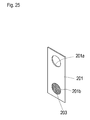
- a partition plate 201 shown in Fig. 25 is fitted at left, right, upper and lower edges thereof so as to cover a gap between motor chamber MC and gear chamber GC.
- holes 201 a and 201b function so that upper hole 201 a allows air to flow therethrough between motor chamber MC and gear chamber GC, lower hole 201b allows fluid to flow therethrough between motor chamber MC and gear chamber GC, and filter 203 traps metal powder mixed in fluid in gear chamber GC before the fluid enters motor chamber MC, similar to the function of upper and lower holes 1y and filter 50 shown in Figs. 8 and 9 .
Landscapes
- Engineering & Computer Science (AREA)
- Power Engineering (AREA)
- Chemical & Material Sciences (AREA)
- Combustion & Propulsion (AREA)
- Transportation (AREA)
- Mechanical Engineering (AREA)
- Life Sciences & Earth Sciences (AREA)
- Environmental Sciences (AREA)
- Arrangement Or Mounting Of Propulsion Units For Vehicles (AREA)
- Connection Of Motors, Electrical Generators, Mechanical Devices, And The Like (AREA)
- Harvester Elements (AREA)
- Motor Or Generator Frames (AREA)
Abstract
Description
- The present invention relates to an electric transaxle unit including a casing incorporating an electric motor for driving an axle.
- Recently, an electric transaxle unit having a casing, which incorporates an electric motor having variable output and supports an axle driven by the electric motor, is used for various vehicles or devices. In a typical electric transaxle unit, a motor shaft, serving as an output shaft of the electric motor, is disposed in the casing so as not to be coaxial to the axle, a deceleration gear train is disposed in the casing so as to be interposed between the motor shaft and the axle, and a brake is disposed in the casing so as to be adapted to brake any element in a power train ranging between the motor shaft and the axle via the deceleration gear train. A typical vehicle using the electric transaxle unit is a hybrid car. The electric transaxle unit is also adaptable to an electric wheelchair and various working vehicles such as a lawn mower and a skid steering loader.
- Standardization is an important factor to economize manufacture of the electric transaxle unit. Especially, in the case that a vehicle is equipped with a pair of left and right electric transaxle units for driving respective left and right wheels, each electric transaxle unit is desired to be able to serve as either the left or right electric transaxle unit. In this regard, each electric transaxle unit is desired to be convenient to attach to either a left or right portion of a frame of a vehicle or the like, or is desired to be convenient to operatively connect to either a left or right link member connected to a brake operation device.
- Further, the electric transaxle unit is desired so that its components can be simply assembled, and the assembled components are firmly settled. Further, in consideration that the electric transaxle unit has an indispensable electric wire connected to the electric motor in the casing and extended outward from the casing, the casing is desired to be sealed against the electric wire penetrating a wall of the casing surely and simply during assembling of the electric transaxle unit.
- An electric transaxle unit according to the invention has a basic structure such that the electric transaxle unit comprises a casing, an electric motor and an axle. The casing incorporates the electric motor and supports the axle driven by the electric motor. Further, in a first aspect of the invention, the electric transaxle unit further comprises a motor shaft serving as an output shaft of the electric motor, and a deceleration gear train. The motor shaft is disposed in the casing so as not to be coaxial to the axle. The deceleration gear train is disposed in the casing so as to be interposed between the motor shaft and the axle.
- A first object of the invention is to provide the electric transaxle unit in the first aspect, which is convenient to mount onto either the left or right portion of a vehicle body or the like so as to serve as either a left or right electric transaxle unit, while the left and right electric transaxle units are equipped on the vehicle or the like so that one electric transaxle unit corresponds to the other electric transaxle unit vertically inversed.
- To achieve the first object, in the electric transaxle unit of the first aspect, the casing includes an attachment portion to be attached to a frame. The attachment portion has a constant height from a center axis of the axle regardless of whether the casing is vertically inversed. Therefore, when the electric transaxle units that are identical to each other are paired and arranged as left and right electric transaxle units to be mounted onto respective left and right portions of the frame of a vehicle or the like so that one electric transaxle unit corresponds to the other electric transaxle unit inversed vertically, the electric transaxle units have the respective attachment portions to be attached to the frame at equal heights from the enter axes of the respective left and right axles, thereby being available to be attached to the frame. Consequently, the electric transaxle unit is standardized to reduce costs.
- Preferably, in the electric transaxle unit of the first aspect, the casing includes first and second divisional casing parts joined to each other to have a horizontal joint surface therebetween. The axle has an axis disposed on the horizontal joint surface. The first divisional casing part includes a first attachment portion, and the second divisional casing part includes a second attachment portion, so that each of the first and second attachment portions can serve as the attachment portion of the casing to be attached to the frame, and the first and second attachment portions are equally distant in vertical from the horizontal joint surface therebetween. Therefore, either the first or second attachment portion serves as the attachment portion of the casing to be attached to the frame, which has a constant height regardless of whether the casing is vertically inversed. In this regard, to equip a pair of left and right electric transaxle units on a vehicle, the left and right electric transaxle units are necessarily arranged to have the respective axles that are as high as each other. When the pair of electric transaxle units serve as the left and right electric transaxle units arranged so that one electric transaxle unit corresponds to the other electric transaxle unit vertically inversed, the first attachment portion of one electric transaxle unit and the second attachment of the other electric transaxle unit are equally distant in vertical from the respective axles and are disposed at equal heights, thereby serving as the attachment portions of the casings of the respective left and right electric transaxle units to be attached to the frame.
- Further preferably, the motor shaft is disposed to have an axis disposed on the horizontal joint surface. Therefore, the axis of the motor shaft is kept at a constant height because the axis of the axle is also disposed on the horizontal joint surface, even if the electric transaxle unit serves as either of the left and right electric transaxles equipped on a vehicle while one electric transaxle unit corresponds to the other electric transaxle unit vertically inversed.
- A second object of the invention is to provide the electric transaxle in the first aspect, further comprising a brake disposed in the casing so as to be adapted to brake any element in a power train between the motor shaft and the axle via the deceleration gear train, wherein the electric transaxle unit is convenient to connect to either the left or right link members connected to a brake operation device so as to serve as either a left or right electric transaxle unit, while the left and right electric transaxle units are equipped on the vehicle or the like so that one electric transaxle unit corresponds to the other electric transaxle unit vertically inversed.
- To achieve the second object, the electric transaxle unit having the brake includes a brake arm for operating the brake, the brake arm being extended outward from the casing. The brake arm has a connection portion which is kept at a constant height from a center axis of the axle regardless of whether the casing is vertically inversed. Therefore, when the electric transaxle units that are identical to each other are paired and arranged as left and right electric transaxle units to be equipped on a vehicle or the like having a brake operation device and a pair of left and right link members extended at equal heights from the brake operation device so that one electric transaxle unit corresponds to the other electric transaxle unit inversed vertically, the connection portions of the brake arms of the respective electric transaxle units are disposed at equal heights from the center axes of the respective left and right axles, thereby being available to be connected to the respective left and right link members connected to the brake operation device. Consequently, the electric transaxle unit is standardized to reduce costs.
- Preferably, in the electric transaxle unit having the brake and the brake arm, the casing includes first and second divisional casing parts joined to each other to have a horizontal joint surface therebetween. The axle has an axis disposed on the horizontal joint surface. The brake arm is extended outward from one of the first and second divisional casing parts so as to have the connection portion disposed at the same height of the horizontal joint surface. In this regard, to equip a pair of left and right electric transaxle units on a vehicle, the left and right electric transaxle units are necessarily arranged to have the respective axles as high as each other. Therefore, when the pair of electric transaxle units serve as the left and right electric transaxle units arranged so that one electric transaxle unit corresponds to the other electric transaxle unit vertically inversed, a height in one electric transaxle unit where its brake arm is extended outward from its casing is different from a height in the other electric transaxle unit where its brake arm is extended outward from its casing, however, both the connection portions of the respective brake arms are disposed at equal heights from the center axes of the respective left and right axles because of their equal heights to those of the respective horizontal joint surfaces.
- Alternatively, preferably, in the electric transaxle unit having the brake and the brake arm, the casing includes first and second divisional casing parts joined to each other to have a horizontal joint surface therebetween. The axle has an axis disposed on the horizontal joint surface. Both the first and second divisional casing parts include respective arm-projection portions adapted to have the brake arm extended outward therefrom. The arm-projection portions of the respective first and second divisional casing parts are evenly distant in vertical from the horizontal joint surfaces. One of the arm-projection portions of the respective first and second divisional casing parts is selected so as to have the brake arm extended outward therefrom. Therefore, when the pair of electric transaxle units serve as the left and right electric transaxle units arranged so that one electric transaxle unit corresponds to the other electric transaxle unit vertically inversed, one electric transaxle unit has its brake arm extended outward from the arm-projection portion of its first divisional casing part, and the other electric transaxle unit has its brake arm extended outward from the arm-projection portion of the second divisional casing part, so that a height in one electric transaxle unit where its brake arm is extended outward from its casing is equal to a height in the other electric transaxle unit where its brake arm is extended outward from its casing. Consequently, the brake arms do not require complicated processing, e.g., bending, to ensure the equal heights of the connection portions of the respective brake arms.
- A third object of the invention is to provide the electric transaxle unit in the first aspect, wherein the axle can be optionally manually made to be rotatably free from the motor shaft of the electric motor.
- To achieve the third object, in the electric transaxle unit of the first aspect, a manually operable clutch is disposed in the casing on any portion of a power train between the motor shaft and the axle via the deceleration gear train, so that the axle can be isolated from an output power of the electric motor by manual operation to disengage the clutch. Therefore, regarding a vehicle equipped with the electric transaxle unit having a clutch, a drive wheel drivingly connected to the axle can be made to be rotatably free from the electric motor by the manual operation for disengaging the clutch for convenient pushing of the vehicle by a person's hand or towing of the vehicle, in case the electric motor is stationary because it is broken or if there is trouble with an electric wire connected to the electric motor, or if the battery for the electric motor dies.
- A fourth object of the invention is to provide an economized vehicle equipped with a pair of left and right electric transaxle units for driving respective left and right wheels.
- To achieve the fourth object, a vehicle comprises a pair of left and right wheels, and a pair of left and right electric transaxle units for driving the respective left and right wheels. The left and right electric transaxle units are identical to each other. Each of the left and right electric transaxle units is the electric transaxle unit in the first aspect, which comprises a casing, an electric motor, an axle, a deceleration gear train and a brake. The casing incorporates the electric motor, and supports the axle driven by the electric motor. A motor shaft serving as an output shaft of the electric motor is disposed in the casing so as not to be coaxial to the axle. The deceleration gear train is disposed in the casing so as to be interposed between the motor shaft and the axle. The brake is disposed in the casing so as to be adapted to brake any element in a power train between the motor shaft and the axle via the deceleration gear train. Therefore, the electric transaxle units, which are identical to each other, i.e., have the common structure, are paired to serve as the left and right electric transaxle units equipped on the vehicle, so that the electric transaxle unit is standardized for economizing the vehicle.
- Preferably, in the vehicle, the left and right electric transaxle units are arranged so that one electric transaxle unit corresponds to the other electric transaxle unit vertically inversed.
- Preferably, in the vehicle, the left and right electric transaxle units have the respective axles disposed on a coaxial line extended laterally of the vehicle. The left and right electric transaxle units are line-symmetric with respect to a fore-and-aft extended centerline of the vehicle at the center of the coaxial line between the left and right axles.
- Alternatively, preferably, in the vehicle, the left and right electric transaxle units have the respective axles disposed coaxially to each other. The left and right electric transaxle units are point-symmetric with respect to a lateral center point of a vehicle body disposed on a coaxial line of the axles between the left and right axles disposed coaxially to each other.
- Therefore, any one of various arrangements of the left and right electric transaxle units can be selected to correspond to the design of the vehicle.
- A fifth object of the invention is to provide the electric transaxle unit having the basic structure, wherein the casing is surely and simply sealed against an electric wire penetrating a wall of the casing during assembly of the electric transaxle unit.
- To achieve the fifth object, in the electric transaxle unit having the basic structure, the casing includes first and second divisional casing parts joined to each other so as to have a joint surface therebetween, and includes a hole dividable between the first and second casing parts by the joint surface. A wire-passage member through which an electric wire is passed is fitted in the hole so as to be clamped between the first and second divisional casing parts. Therefore, a part of the wire-passage member is fitted into a divisional part of the hole in one of the first and second divisional casing parts before the first and second divisional casing parts are joined to each other. Then, the remaining part of the wire-passage member is naturally fitted into another divisional part of the hole in the other of the first and second divisional casing parts by joining the first and second divisional casing parts to each other. In this way, the wire-passage member is clamped between the first and second divisional casing parts so as to surely seal the interior of the casing against the electric wire entering the inside of the casing from the outside of the casing.
- Preferably, in the electric transaxle unit having the wire-passage member, the wire-passage member fitted in the hole is shaped, when viewed along the joint surface, to have a first half extended from the joint surface into the first divisional casing part perpendicularly to the joint surface, and a second half extended from the joint surface into the second divisional casing part perpendicularly to the joint surface. Each of the first and second halves has a width along the joint surface, so that the width is reduced as it goes further distant from the joint surface. Further preferably, each of the hole and the wire-passage member fitted in the hole is rhombic when viewed along the joint surface so as to have a diagonal extended on the joint surface. Therefore, deformation of the wire-passage member clamped between the first and second divisional casing parts is restricted, thereby being advantageous in durability and thereby reducing deviation of the electric wire passed through the wire-passage member.
- A sixth object of the invention is to provide the electric transaxle unit having the basic structure, wherein an output rotary member of the electric motor and a motor shaft serving as an output shaft of the electric motor are easily and firmly assembled and fastened to each other.
- To achieve the sixth object, the output rotary member is a hollow member having a tapered inner peripheral surface. The motor shaft is supported in the casing and is drivingly connected to the axle so as to serve as an output shaft of the electric motor. The motor shaft has a tapered outer peripheral surface. The tapered inner peripheral surface of the output rotary member and the tapered outer peripheral surface of the motor shaft are fittingly pressed against each other by axial relative movement of the output rotary member and the motor shaft, whereby the output rotary member is fixed on the motor shaft. Therefore, the output rotary member and the motor shaft are firmly assembled and fastened to each other so as to eliminate deviation therebetween causing vibration or noise.
- A seventh object of the invention is to provide an electric transaxle unit having the basic structure, wherein the electric transaxle unit comprises a motor assembly disposed in the casing so as to serve as the electric motor for driving the axle, wherein the motor assembly includes a motor shaft drivingly connected to the axle, wherein the motor assembly is prevented from leaking noise outward therefrom through a gap adjacent to a bearing journaling the motor shaft, and wherein the motor shaft and the bearing are assembled in the motor assembly so as to be prevented from deviating in the axial direction of the motor shaft.
- To achieve the seventh object, the motor assembly of the electric transaxle unit having the basic structure includes a pair of first and second bearings fitted onto the motor shaft at respective inner peripheral surfaces thereof, a rotor having a magnet and fixed on the motor shaft, a stator having an armature winding and secured to the casing, and a support frame detachably fixed to the stator. The stator is formed with a first retaining projection, and is fitted onto an outer peripheral surface of the first bearing so as to have the first retaining projection on a distal side of the first bearing opposite to the second bearing in the axial direction of the motor shaft. The support frame is formed with a second retaining projection, and is fitted onto an outer peripheral surface of the second bearing so as to have the second retaining projection on a distal side of the second bearing opposite to the first bearing in the axial direction of the motor shaft. One of the first and second retaining projections abuts against the corresponding first or second bearing so that the other of the first and second retaining projections has a gap from the corresponding first or second bearing. The motor assembly further includes a gap-filling member fitted in the gap so as to prevent the corresponding first or second bearing from moving towards the corresponding first or second retaining projection in the axial direction of the motor shaft. Therefore, due to the gap-filling member, the motor assembly is prevented from leaking noise outward therefrom through the gap.
- Preferably, the motor shaft includes a plurality of portions having different diameters so as to have a pair of steps abutting against axially proximal end surfaces of the respective first and second bearings so as to prevent the first and second bearings from moving towards each other in the axial direction of the motor shaft. The rotor has a tapered inner peripheral surface. The motor shaft has a tapered outer peripheral surface fitted to the tapered inner peripheral surface of the rotor so as to be pressured by the rotor in one axial direction of the motor shaft towards one of the first and second bearings which abuts against the corresponding first or second retaining projection. Therefore, the motor shaft and the first and second bearings are assembled in the motor assembly so as to be prevented from deviating in the axial direction of the motor shaft.
- An eighth object of the invention is to provide the electric transaxle unit having the basic structure and a motor assembly serving as the electric motor, wherein components of the motor assembly in the casing, especially, its rotor and its armature winding, are effectively cooled.
- To achieve the eighth object, in the electric transaxle unit having the basic structure, the casing is formed therein with a motor chamber, and the motor assembly is disposed in the motor chamber so as to drive the axle. The motor assembly includes a motor shaft having an axis and drivingly connected to the axle, a rotor having a magnet and fixed on the motor shaft, a stator having an armature winding and secured to the casing, and a support frame fixed to the stator so as to journal the motor shaft. The rotor and the armature winding are disposed in a space surrounded by the stator and the support frame fixed to the stator. The support frame fixed to the support plate has an opening through which the rotor and the armature winding are exposed to the motor chamber. Therefore, the rotor and the armature winding are effectively cooled by air or fluid in the motor chamber.
- Preferably, the casing is constituted by joining a pair of casing halves to each other through a joint surface, and the support frame is fixed to one of the casing halves so as to secure the stator to the casing. Therefore, the stator can be simplified.
- Preferably, the motor chamber is filled therein with fluid so as to serve as a fluid sump which can supply fluid to the rotor and the armature winding through the opening of the support frame. Therefore, the rotor and the armature can be effectively cooled. Preferably, the casing has fins on an outer surface corresponding to the motor chamber. Therefore, the motor assembly in the motor chamber can be effectively cooled.
- These, further and other objects, features and advantages of the invention will appear more fully from the following description with reference to the attached drawings.
-
Fig. 1 is a schematic side view of a riding lawn mower 100 serving as an embodiment of a vehicle equipped with a pair of electric transaxle units A according to the invention, wherein electric transaxle units A are identical to each other, and serve as left and right electric transaxle units AL and AR for driving respective rear wheels 12 (as a generic name of left and rightrear wheels -
Fig. 2 is a sectional plan view of lawn mower 100. -
Fig. 3 is a perspective view of left and right electric transaxle units AL and AR while being attached to avehicle body frame 10 of lawn mower 100. -
Fig. 4 is a schematic fragmentary sectional front view of lawn mower 100 equipped with a rear-discharge mower, showing its structure supporting left and right electric transaxle units AL and AR. -
Fig. 5 is a plan view of lawn mower 100 equipped with the pair of electric transaxle units A that are identical to each other, wherein the pair of electric transaxle units A serve as left and right electric transaxle units AL and AR are point-symmetric with respect to a laterally central point of the vehicle body. -
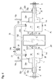
Fig. 6(a) is a sectional plan view of electric transaxle unit A having acasing 1 from which acasing half 1B has been removed, showing a remainingcasing half 1A and inner and outer structures ofcasing half 1A. -
Fig. 6(b) is an enlarged view of a principal portion ofFig. 6(a) showing surroundings around amotor shaft 3 in amotor assembly 2 serving as an electric motor for driving anaxle 4. -
Fig. 7 is a sectional rear view of electric transaxle unit A whenmotor assembly 2 andmotor shaft 3 in a motor chamber MC incasing 1 are viewed from a gear chamber GC side. -
Fig. 8 is a right side view partly in section of right electric transaxle unit AR on an assumption that left and right electric transaxle units AL and AR are equipped on lawn mower 100 in the way shown inFigs. 1 to 3 . -
Fig. 9 is a left side view partly in section of left electric transaxle unit AL on the assumption that left and right electric transaxle units AL and AR are equipped on lawn mower 100 in the way shown inFigs. 1 to 3 . -
Fig. 10 is a fragmentary sectional view of electric transaxle unit A showing arubber plug 44 for wiring a harness, rubber plug 44 being clamped betweencasing halves -
Fig. 11 is a fragmentary sectional plan view of electric transaxle unitA having casing 1 from which casing half 1B has been removed, showing remainingcasing half 1A and inner and outer structures ofcasing half 1A, whereinmotor assembly 2 is installed into motor chamber MC by fastening a motorshaft support frame 37 tocasing half 1A. -
Fig. 12 is a sectional rear view of electric transaxle unit A having the structure shown inFig. 12 when amotor assembly 2 and amotor shaft 3 in a motor chamber MC incasing 1 are viewed from a gear chamber GC side. -
Fig. 13 is a fragmentary sectional plan view of electric transaxle unitA having casing 1 from which casing half 1B has been removed, showing remainingcasing half 1A and inner and outer structures ofcasing half 1A, wherein a coolingfan 25 is disposed incasing 1. -
Fig. 14 is a fragmentary sectional plan view of electric transaxle unitA having casing 1 from which casing half 1B has been removed, showing remainingcasing half 1A and inner and outer structures ofcasing half 1A, wherein adriver 84 is disposed incasing 1. -
Fig. 15 is a fragmentary sectional plan view of electric transaxle unitA having casing 1 from which casing half 1B has been removed, showing remainingcasing half 1A and inner and outer structures ofcasing half 1A, whereinmotor assembly 2 is installed intocasing 1 after casing 1 is completely constituted by joiningcasing halves -
Fig. 16 is a fragmentary sectional plan view of electric transaxle unitA having casing 1 from which casing half 1B has been removed, showing remainingcasing half 1A and inner and outer structures ofcasing half 1A, wherein electric transaxle unit A is provided with a pair ofaxles 104 and a differential mechanism D differentially connectingaxles 104 to each other. -
Fig. 17 is a fragmentary sectional view ofcasing halves respective breather ports 1p, whereinbreather ports 1p are disposed at top and bottom ends of amotor housing portion 1m ofcasing 1 of electric transaxle unit A, and haverespective check balls 46 therein to correspond tomotor assembly 2 whenmotor assembly 2 is a dry type motor. -
Fig. 18 is a fragmentary sectional plan view of electric transaxle unitA having casing 1 from which casing half 1B has been removed, showing remainingcasing half 1A and inner and outer structures ofcasing half 1A, wherein a speed-shift gear mechanism is installed in gear chamber GC. -
Fig. 19 is a plan view of a pair of alternative electric transaxle units B (left and right electric transaxle units BL and BR) supported by avehicle body frame 10 of lawn mower 100. -
Fig. 20 is a sectional front view of one of left and right electric transaxle units BL and BR (i.e., representative right electric transaxle unit BR) supported byvehicle body frame 10 of lawn mower 100. -
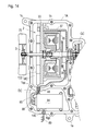
Fig. 21 is a sectional plan view of electric transaxle unit B having acasing 200 from which acasing half 200B has been removed, showing a remainingcasing half 200A and inner and outer structures ofcasing half 200A. -
Fig. 22 is a cross sectional view taken along V-V line ofFig. 21 . -
Fig. 23 is a cross sectional view taken along W-W line ofFig. 21 . -
Fig. 24 is a cross sectional view taken along a line marked by an arrow X ofFig. 22 . -
Fig. 25 is a perspective view of apartition plate 201 adaptable to electric transaxle unit B. -
Fig. 26 is a fragmentary sectional plan view of electric transaxle unitB having casing 200 from whichcasing half 200B has been removed, showing remainingcasing half 200A and inner and outer structures ofcasing half 200A, wherein electric transaxle unit A is provided with a pair ofaxles 204 and a differential mechanism D differentially connectingaxles 204 to each other. -
Fig. 27 is a sectional plan view of an alternative electric transaxle unit C having acasing 300 dividable into left, right and middle casing parts by vertical surfaces. -
Fig. 28 is a sectional plan view of a portion of electric transaxle unit C where a motor shaft supporter is engaged with the middle casing part via a dowel pin. -
Fig. 29 is a cross sectional view taken along Y-Y ling ofFig. 27 . -
Fig. 30 is a cross sectional view taken along Z-Z line ofFig. 29 . -
Fig. 31 is a cross sectional view of a mower unit MU. - An electric transaxle unit according to the invention is adaptable to a later-discussed riding lawn mower having a mid-mounted mower unit, a riding lawn mower having a front-mounted mower unit, a wheelchair, and various industrial vehicles such as a skid steering loader.
- Referring to
Figs. 1 to 4 , a structure of a riding lawn mower 100 serving as a vehicle equipped with electric transaxle units A (as a generic name of left and right electric transaxle units AL and AR) according to an embodiment of the present invention. In hereinafter descriptions, the forward traveling direction of lawn mower 100 will be referred to as "forward," and on this assumption, each of positions and directions will be referred to as front, rear, left, right, upper or lower. Further,Fig. 4 is based on an assumption that lawn mower 100 is provided with a mower unit adapted to discharge mowed grass in a different manner from that of a mower unit MU of lawn mower 100 shown inFigs. 1 and2 , and has a structure supporting electric transaxle units A, the structure being different from that shown inFig. 3 . However,Fig. 4 will be used as a front view of left and right electric transaxle units AL and AR in lawn mower 100 shown inFigs. 1 to 3 . - Lawn mower 100 includes a vehicle body frame (chassis) 10. Left and right drive wheels 12 (as a generic name of left and
right drive wheels vehicle body frame 10. In lawn mower 100, a pair of left and right electric transaxle units A for drivingrespective drive wheels 12 are disposed below the rear portion ofvehicle body frame 10. If lawn mower 100 is provided with a front-mounted mower unit, rear wheels are casters or Ackerman and Junt type forcedly steered wheels as usual. In this case, a pair of left and right electric transaxle units A are disposed below a front portion ofvehicle body frame 10 so as to drive front wheels. - Each electric transaxle unit A includes a
casing 1 journaling anaxle 4 serving as a central axial shaft ofdrive wheel 12.Casing 1 incorporates amotor assembly 2 serving as an electric motor for drivingaxle 4, a deceleration gear train G drivingly connectingmotor assembly 2 toaxle 4, and so on. Ahub 5 ofdrive wheel 12 is fixed on a left or right distal end ofaxle 4. In this regard, as shown inFig. 6(a) , a key 5a is interposed between an inner peripheral portion ofhub 5 and the distal end ofaxle 4, andhub 5 is fastened toaxle 4 by anut 5b so thathub 5 is fixed onaxle 4. - In lawn mower 100, electric transaxle units AL and AR are disposed below respective left and right
side plate portions 10a ofvehicle body frame 10, so thatcasings 1 of respective electric transaxle units AL and AR are supported and fixed onvehicle body frame 10 in a later-discussed manner. The distal end ofaxle 4 projects outward from a right or left distal end of eachcasing 1 and is fitted to arim 12a ofdrive wheel 12. - A driver's
seat 13, aplatform 14, adashboard 11a and abonnet 11 are supported onvehicle body frame 10. Anaccelerator pedal 15 is provided at a foot portion ofdashboard 11a, and asteering wheel 16 is extended from an upper portion ofdashboard 11a. The hereinafter description will be based on the assumption that lawn mower 100 is provided withsteering wheel 16 serving as a steering operation device. Alternatively, a pair of left and right operation levers 160 for both traveling speed change and steering may be provided as drawn in phantom lines inFig. 1 . Each of the pair of operation levers 160 is provided with a device for converting the rotation degree and direction thereof operated by an operator into an electric signal. Alternatively, a joystick or a mouse serving as an input device of a computer may be provided. - Similar to operation of an accelerator pedal in a normal motorcar,
accelerator pedal 15 is adapted to be depressed by an operator sitting on driver'sseat 13 so that output rotary speeds ofmotor assemblies 2 of both left and right electric transaxle units AL and AR are increased or decreased according to the depression degree ofaccelerator pedal 15, so as to control simultaneous and even increase or decrease of speeds of left andright drive wheels steering wheel 16 is adapted to be rotated by the operator sitting on driver'sseat 13 so that the output rotary speeds of left and right electric transaxle units AL and AR are differentially controlled according to the rotational direction and degree ofsteering wheel 16, so as to differentially drive left andright drive wheels - Further, lawn mower 100 is equipped with an unshown brake operation device (such as a pedal or lever) and an unshown forward/backward traveling direction switching operation device (such as a lever or a switch), serving as other operation devices to be operated by the operator sitting on driver's
seat 13. The brake operation device is connected to a later-discussedbrake arm 60. Alternatively, to switch the forward/backward traveling direction of lawn mower 100, for example,accelerator pedal 15 may be a seesaw-shaped pedal whose front end portion is adapted to be depressed for forward traveling, and whose rear end portion is adapted to be depressed for backward traveling. Alternatively, different accelerator pedals may be provided so that one is provided for forward traveling and the other is for backward traveling. -
Front wheels 17 are supported by respective left and right ends of the front end portion ofvehicle body frame 10. The front end portion ofvehicle body frame 10 is formed on the left and right ends thereof withrespective bosses 10b. Avertical pivot shaft 17a for horizontally rotating correspondingfront wheel 17 is inserted into each ofbosses 10b rotatably relative tovehicle body frame 10. Eachpivot shaft 17a projects at a top thereof upward from correspondingboss 10b and is inserted into a frontwheel steering box 18 incorporating a mechanical or electric front wheel steering system. The front wheel steering system controls rotations of left andright pivot shafts 17a based on the rotational degree of direction ofsteering wheel 16, thereby controlling the leftward or rightward directions of left and rightfront wheels 17. Alternatively,front wheels 17 may be casters. - Lawn mower 100 is equipped with a mower unit MU in front of left and right electric transaxle units A, as shown in
Figs. 1 and2 . Here, description will now be given of mower unit MU including amower deck 19,blades 20 andmotor assemblies 21 with reference toFigs. 1 ,2 and31 .Mower deck 19 incorporates threeblades 20, and is vertically movably supported belowvehicle body frame 10 via asuspension link 19a such as show inFig. 31 . Eachblade 20 has avertical drive shaft 20a at a center axis thereof, and is provided ondrive shaft 20a with amotor assembly 21 serving as an electric motor for controlling driving ofcorresponding blade 20. Lawn mower 100 is equipped with an unshown mower driving on/off setting operation device (such as a switch or a lever) for selecting either driving or non-driving ofblades 20. - As shown in
Fig. 31 ,motor assembly 21 includes arotor 212 and astator 215.Rotor 212 is fixed ondrive shaft 20a rotatably integrally withdrive shaft 20a.Stator 215 is fitted ondrive shaft 20a viabearings 214 rotatably relative to driveshaft 20a. An upwardly opened cup-shapedrotor 212 is fixed ontodrive shaft 20a at a center bottom portion thereof, and is extended vertically upward from the center bottom portion thereof so as to havepermanent magnets 213 fixed on an inner peripheral surface thereof.Armature windings 216 are fixed onto an outer peripheral surface of a vertical core portion thereof fitted arounddrive shaft 20a viabearings 214 so as to facepermanent magnets 213. In this way,motor assembly 21 is flattened to have a vertical axial length and a horizontal diametric width that is larger than the vertical axial length, and is disposed withinmower deck 19, whereby a top portion ofmower deck 19 is formed as a horizontal flat plate-shaped portion without an upper portion ofmotor assembly 21 projecting therefrom. Therefore, the limit position of mower unit MU when raised can be heightened without interfering with the vehicle body of lawn mower 100. - A top portion of
stator 215 is expanded in a horizontal discoid shape, and is vibro-isolatedly secured to the horizontal top plate portion ofmower deck 19 together with arotor support frame 219 via vibro-isolatingrubbers 217 and bolts-and-nuts 218. Anopening 19b is opened in the horizontal discoid top portion ofmower deck 19 so as to face a top surface ofstator 212. A wire-collection box 221 is fixed on the top surface ofstator 215 and is disposed inopening 19b, and a later-discussedharness 87 is extended upward from wire-collection box 221. Abellow 222 is extended upward from the horizontal top plate portion ofmower deck 19 so as to coveropening 19b, wire-collection box 221 andharness 87. -
Rotor support frame 219 is extended downward from a top portion thereof fastened tomower deck 19 via vibro-isolatedrubbers 217 and bolts-and-nuts 218 so as to journal the bottom portion ofrotor 212 via abearing 220 at a bottom portion thereof An upwardly opened cup-shapedprotector 211 is fixed at a center bottom portion thereof ontodrive shaft 20a between the center bottom portion ofrotor 212 and the center portion ofblade 20. In this way,stator 215 androtor support frame 219 are secured tomower deck 19, and meanwhile,rotor 212,protector 211,blade 20 and driveshaft 20a are rotatable integrally with one another, and are rotatable relative tostator 215 and rotor support frame. -
Mower deck 19 is formed withvent holes 19c in a vertical plate-shaped portion thereof so as to introduce the outside air thereinto.Protector 211 is formed withair suction holes 211a in a peripheral vertical plate-like portion thereof, withfan blades 211b projecting from respective air suction holes 211 a, and with air discharge holes 211c in a horizontal bottom plate-like portion thereof. Therefore,protector 211 rotates together withblade 20 so as to introduce air intomower deck 19 viavent holes 19c, and thereinto viaair suction holes 211a, to blow the air ontomotor assembly 21, and to discharge the air outward therefrom via air discharge holes 211 b. InFig. 31 , arrows define this flow of air. In this way,protector 211 protectsmower assembly 21 from grass mowed byblade 20 as a main function thereof, and also serves as a cooling fan formotor assembly 21. - Mower unit MU illustrated in the present application is provided with three
motor assemblies 21 provided ondrive shafts 20a of respectivetriple blades 20. Alternatively, one oftriple blades 20 may serve as adrive blade 20 provided withmotor assembly 21 ondrive shaft 20a thereof, and driveshafts 20a of the other twoblades 20 may be drivingly connected to driveshaft 20a ofdrive blade 20 via a belt or the like. - Mower unit MU of lawn mower 100 shown in
Figs. 1 and2 is a side-discharging mower unit which discharges grass mowed byblades 20 at one side ofmower deck 19. Alternatively, if lawn mower 100 is equipped with a rear-discharging mower unit having a grass collection box disposed at a rear portion of the vehicle body, aduct 190 is extended rearward frommower deck 19 to the grass collection box so as to pass a space between left and right electric transaxle units AL and AR, as shown inFig. 4 . - A
battery 22, such as a secondary battery or a fuel battery, is provided inbonnet 11 abovevehicle body frame 10 so as to supply electric power toelectric motor assemblies 2 of electric transaxle units AL and AR and toelectric motor assemblies 21 for drivingrotary blades 20.Battery 22 is preferably provided on a front upper portion ofvehicle body frame 10 as drawn in solid lines inFig. 1 , so as to be balanced in weight with electric transaxle units A supported at the rear portion ofvehicle body frame 10. Alternatively,battery 22 may be disposed above the rear portion ofvehicle body frame 10 above electric transaxle units A, as drawn in phantom lines inFig. 1 . - An electric control system for
motor assemblies Fig. 2 will be described. Acontroller 80 is disposed at a suitable position in lawn mower 100. A travelingspeed setting device 81, aturn setting device 82 and a mower-driving on/off settingdevice 83 are electrically connected to an input interface ofcontroller 80 so as to serve as input means for inputting respective operation signals tocontroller 80. - Traveling
speed setting device 81 generates an electric signal corresponding to a depression degree ofaccelerator pedal 15, and transmits the electric signal tocontroller 80. An unshown traveling direction setting device receives a signal from the foresaid unshown forward/backward traveling direction switching device so as to select whether the electric signal corresponding to the depression degree ofaccelerator pedal 15 is made into a positive value or a negative value. Turn settingdevice 82 generates an electric signal corresponding to a rotation direction and degree of steering wheel 16 (or rotation directions and degrees of left and right operation levers 160) and transmits the electric signal tocontroller 80. Mower driving on/offsettingdevice 83 generates an electric signal corresponding to the operation of the unshown mower driving on/off setting device selecting whether the mower unit (i.e., rotary blades 20) is driven or not, and transmits the electric signal tocontroller 80. - An output interface of
controller 80 is connected to a pair ofdrivers 84 serving as control means for controllingrespective motor assemblies 2 of left and right electric transaxle units AL and AR, and is connected to adriver 86 serving as a control means for uniformly controllingmotor assemblies 21 of allblades 20. Aharness 85 is extended from eachdriver 84 and is connected tomotor assembly 2 of corresponding left or right electric transaxle unit A. Harnesses 87 are branched fromdriver 86 and are connected torespective motor assemblies 21. - In this regard, a unit having an inverter and a transmitter-receiver is referred to as the "driver."
Controller 80 controls the respective inverters ofdrivers aforesaid setting devices drivers corresponding motor assembly harness motor assembly - Incidentally, in
Fig. 2 , bothdrivers 84 for respective electric transaxle units A are disposed outside respective electric transaxle units A, and eachharness 85 is interposed between correspondingdriver 84 andcorresponding casing 1. Alternatively,driver 84 may be disposed incasing 1 as in a later-discussed alternative embodiment (Fig. 14 ). -
Motor assemblies 21 are provided with sensors (not shown) for detecting a resistance force against the rotary force ofblade 20 or for detecting temperatures ofmotor assemblies 21, andcontroller 80 monitors a mowing load, i.e., resistance of mowed grass againstblades 20, by use of the detection of the sensors. Whencontroller 80 recognizes that the mowing load is excessive,controller 80 automatically controlsmotor assemblies 2 or the like so as to reduce the traveling speed of lawn mower 100, thereby reducing load onmotor assemblies 21 and achieving a sufficient effect of mowing. - Further,
controller 80 automatically controlsmotor assemblies 21 so as to electricallybrake drive shafts 20a for an optional time aftercontroller 80 receives an electric signal based on a manual operation of the mower driving on/off setting device for driving off mower unit MU, or receives an electric signal automatically issued when working mower unit MU needs braking ofblades 20, such as when mower unit MU is raised or when lawn mower 100 is backed. Energies generated by brakingmotor assemblies 21 are regenerated as electric energies for drivingmotor assemblies - Left and right electric transaxle units AL and AR are a pair of standardized electric transaxle units A (having common structures) arranged for driving respective left and right
rear wheels vehicle body frame 10, and this configuration ofcasing 1 will be described. - As shown in
Fig. 1 and others, casing 1 includes a pair of upper andlower casing halves vehicle body frame 10, the respective open surfaces of its upper andlower casing halves casing half 1A surrounding its open surface is fastened to a portion of casing half 1B surrounding its open surface bybolts 29 shown inFigs. 6(a) ,8 and9 . - Mutually joined
casing halves motor shaft 3, serving as an output shaft ofelectric motor assembly 2, and an axis of anaxle 4 are disposed parallel to each other (not coaxially to each other) and on joint surface J, so thatmotor shaft 3 andaxle 4 are clamped betweencasing halves casing 1.Motor shaft 3 projects at one end portion thereof outward from casing 1 so as to be fixedly provided thereon with a coolingfan 25. In an embodiment shown inFigs. 1 and2 ,motor shaft 3 projects laterally proximally outward from casing 1 (i.e., toward the partner electric transaxle unit A), and coolingfan 25 is fixed on the projecting end portion ofmotor shaft 3. Alternatively, as discussed later,motor shaft 3 may project at another opposite end portion thereof outward from casing 1 so as to be fixedly provided thereon with coolingfan 25, or coolingfan 25 may be disposed incasing 1. - In lawn mower 100, electric transaxle units A are arranged so that their
axles 4 are extended laterally distally outward fromrespective casings 1 andmotor shafts 3 are extended laterally in front ofaxles 4. On an assumption of this arrangement of electric transaxle units A, casing halves 1A and 1B of each electric transaxle unit A are apparently shaped so as to have a shell-shapedmotor housing portion 1m at their front end portions, to have agear housing portion 1r extended rearward from a lateral distal end ofmotor housing portion 1m, and to have anaxle housing portion 1s which is extended laterally distally fromgear housing portion 1r so as to supportaxle 4 laterally horizontally. - In this embodiment, casing halves 1A and 1B are different from each other so that casing
half 1A incorporates acounter shaft 66 of deceleration gear train G betweenmotor shaft 3 andaxle 4 and has a boss portion 1Aa supporting abrake shaft 61 so as to protrude one end portion ofbrake shaft 61 outward from boss portion 1Aa, while casing half 1B does not incorporatecounter shaft 66 and has a boss portion 1Ba from which an end portion ofbrake shaft 61 does not project outward. Alternatively,counter shaft 66 may be supported to be disposed on joint surfaceJ. Brake shaft 61 may be extended at both ends thereof outward from boss portion 1Aa or 1Ba. - Each electric transaxle unit A can be used for driving either
left drive wheel 12L orright drive wheel 12R. In this way, electric transaxle unit A is standardized to reduce costs. When electric transaxle units A are adapted to lawn mower 100 shown inFigs. 1-3 , left electric transaxle unit AL is arranged so that itscasing 1 hascasing half 1A above casing half 1B, and right electric transaxle unit AR is arranged so that itscasing 1 has casing half 1B abovecasing half 1A. In other words, one of right and left electric transaxle units AR and AL can be vertically inversed to serve as the partner left or right transaxle unit AL or AR. - As shown in
Figs. 1-3 ,vehicle body frame 10 is provided thereon with front and rear sub frames 31 and 32 for hanging both left and right electric transaxle units AL and AR.Sub frame 31 is fixed tovehicle body frame 10 by welding or the like. As discussed later,sub frame 32 is detachably attached tovehicle body frame 10. Both left and right electric transaxle units AL and AR are previously integrated withsub frame 32 so as to serve as a sub assembly to be detachably attached tovehicle body frame 10. -
Front sub frame 31 is formed integrally with across bar 31 a, a pair of left and right stays 31b andtabs 31c.Cross bar 31 a is laterally horizontally extended and spanned between bothside plate portions 10a. The pair of left and right stays 31 b are extended vertically downward fromcross bar 31a. Eachstay 31b is bent at a bottom end thereof laterally distally so as to form eachhorizontal tab 31c having a bolt hole. Left and right stays 31b have respective vertical lengths equal to each other, so that left andright tabs 31 c are disposed at respective heights equal to each other. Preferably, left andright tabs 31c are located at respective positions coinciding to each other in the fore-and-aft direction, and have their respective lateral positions so that a lateral distance ofleft tab 31c from a left distal end ofcross bar 31 a is equal to a lateral distance ofright tab 31 c from a right distal end ofcross bar 31a. In other words, insub frame 31, the pair of left and right stays 31b and the pair of left andright tabs 31c are formed laterally symmetrically. -
Rear sub frame 32 is formed integrally with ahorizontal plate portion 32a and a pair of left and rightvertical plate portions 32c.Horizontal plate portion 32a has a length such as to cross left and rightside plate portions 10a, and are disposed beneath left and rightside plate portions 10a ofvehicle body frame 10. A pair of front andrear tabs 32b having respective bolt holes project upward from a top surface of each of left and right portions ofhorizontal plate portion 32a.Tabs 32b are fastened toside plate portions 10a ofvehicle body frame 10 by bolts so as to fixsub frame 32 tovehicle body frame 10. - Each of left and right
vertical plate portions 32c is a plate bent in L-shape when viewed in plan, so as to have a fore-and-aft extended verticalside plate portion 32d and have a laterally extended verticalrear plate portion 32e. Vertical side plate portion32d is extended vertically downward from each of the left and right portions ofhorizontal plate portion 32a. Verticalrear plate portion 32e is extended vertically downward from a rear end of each of the left and right portions ofhorizontal plate portion 32a. Each of left and right verticalside plate portions 32c is bent in L-shape at a bottom thereof so as to form a pair of front andrear tabs 32g extended laterally distally outward from verticalside plate portion 32d and to form a pair of left andright tabs 32f extended rearward from verticalrear plate portion 32e. Each oftabs horizontal plate portion 32a is disposed horizontally, alltabs sub frame 32 is viewed in plan,tabs sub frame 32 andtabs sub frame 32 are arranged laterally symmetrically. - As shown in
Figs. 3 and others, casing 1 of each electric transaxle unit A is formed with aboss 1c extended horizontally and laterally proximately from a lateral proximal front end portion ofmotor housing portion 1m so thatboss 1c contacts each tab 30c at a top surface thereof. Further,casing 1 is formed withbosses 1e extended horizontally rearward from a rear end portion ofgear housing portion 1r and a rear end portion ofaxle housing portion 1s. Further,axle housing portion 1s of eachcasing 1 is formed withbosses 1f on respective front and rear portions of a lateral distal end portion thereof from whichaxle 4 projects outward. - Left and right electric transaxle units AL and AR are fixedly hung from
sub frame 32 by fastening the upside facing horizontal surfaces ofbosses respective casings 1, serving as mount seat surfaces of respective casings 1 (serving as attachment portions ofrespective casings 1 to be attached to vehicle body frame 10), totabs sub frame 32 with respective bolts and nuts 30. Therefore,sub frame 32 and left and right electric transaxle units AL and AR serve as a sub assembly. To mount this sub assembly ontovehicle body frame 10,tabs 32b ofsub frame 32 are fastened to left and rightside plate portions 10a ofvehicle body frame 10 by bolts. Further, the upside horizontal surfaces ofbosses 1c of respective electric transaxle units AL and AR are provided as mount seat surfaces and are fastened totabs 31c ofsub frame 31 by respective bolts and nuts 30. - In this way, left and right electric transaxle units AL and AR are mounted onto
vehicle body frame 10 so that each of electric transaxle units AL and AR is arranged to have itsmotor housing portion 1m on the lateral proximal side of correspondingside plate portion 10a, to have itsaxle housing portion 1s projecting laterally distally outward from correspondingside plate portion 10a, and to haverespective axles 4 disposed on a horizontal coaxial line extended in the lateral direction of lawn mower 100, thereby being line-symmetric when viewed in plan with respect to a fore-and-aft centerline of lawn mower 100 at the lateral center of lawn mower 100. - Alternatively, as shown in
Fig. 4 , ifduct 190 is extended rearward from rear-dischargingmower deck 19 and acrosscasings 1 of left and right electric transaxle units AL and AR, sub frames 131 are fixed on respective left and right side surfaces ofduct 190, andbosses 1c of respective electric transaxle units AL and AR are fastened to respective sub frames 131 by respective bolts and nuts 30. - Alternatively, electric transaxle units A may be disposed to have
axles 4 in front ofmotor assemblies 2 andmotor shafts 3 so as to correspond to a design of lawn mower 100. For example, as shown inFig. 5 , left and right electric transaxle units AL and AR are the pair of identical electric transaxle units A, which are not vertically inversed with respect to each other but are fore-and-aft inversed with respect to each other (so that bothcasings 1 haverespective casing halves 1A aboverespective casing halves 1B in this embodiment), and which are supported byvehicle body frame 10 so as to be point-symmetric with respect to a lateral center point of the vehicle body between units AL and AR when viewed in plan. The lateral center point of the vehicle body is disposed on a coaxial line ofaxles 4 between left andright axles 4 disposed coaxially to each other. In this embodiment, left electric transaxle unit AL is disposed so as to haveaxle 4 rearward ofmotor assembly 2, and right electric transaxle unit AR is disposed so as to haveaxle 4 forward ofmotor assembly 2. - To correspond to the point-symmetric arrangement of left and right electric transaxle units AL and AR, a
sub frame 132 corresponding to subframe 32 is formed on left and right portions thereof with tabs to be fitted tobosses sub frame 132 are point-symmetric with respect to the point on the lateral center of the vehicle body when viewed in plan. Further, a stay is fixed tovehicle body frame 10 forward ofsub frame 132 and is fitted toboss 1c of left electric transaxle unit AL disposed forward ofsub frame 132, and another stay is fixed tovehicle body frame 10 rearward ofsub frame 132 and is fitted toboss 1c of right electric transaxle unit AR disposed rearward ofsub frame 132. - A structure of
casing 1 of each electric transaxle unit A shown inFigs. 6-9 will be described. On eachcasing 1,bosses half 1A with respective boss halves extended from casing half 1B.Representative boss 1e shown inFigs. 7 and8 will be described for describing the forming ofbosses casing half 1A, a boss half 1Be is extended rearward from a rear end of casing half 1B, and boss halves 1Ae and 1Be are matched with each other so as to be formed asboss 1e. As shown inFig. 7 , in right electric transaxle unit AR, a bottom surface of boss half 1Ae (serving as a first attachment portion of the first divisional casing part) serves as a bottom surface ofboss 1e, and a top surface of boss half 1Be (serving as a second attachment portion of the second divisional casing part) serves as the mount seat surface (serving as the attachment of casing 1). As shown inFig. 8 , in left electric transaxle unit AL, a bottom surface of boss half 1Be serves as a bottom surface ofboss 1e, and a top surface of boss half 1Ae serves as the mount seat surface. - Here, a vertical distance of the mount seat surface of boss half 1Ae from the axis of
axle 4 is equal to a vertical distance of the mount seat surface of boss half 1Be from the axis ofaxle 4. Accordingly, the top surface ofboss 1e (i.e., the mount seat surface of boss half 1Be) of left electric transaxle unit AL is as high as the top surface ofboss 1e (i.e., the mount seat surface of boss half 1Ae) of right electric transaxle unit AR. Incidentally, in this embodiment, joint surface J is disposed on the axis ofaxle 4, so that boss halves 1Be and 1Ae are equal to each other in their vertical thickness. In other words, left and right electric transaxle units AL and AR are arranged to have the respective mount seat surfaces at equal heights fromrespective axles 4, and are arranged line-symmetrically in lawn mower 100 as mentioned above, thereby realizing the location ofaxles 4 serving as center axes of respective left andright drive wheels - Due to the above structure of
casing 1 constituted by joiningcasing halves vehicle body frame 10 of lawn mower 100. - As mentioned above, each electric transaxle unit A supports
vertical brake shaft 61 rotatably and slidably in boss 1Aa of casing half 1A thereof. Boss 1Aa of left electric transaxle unit A, serving as an arm-projection portion from which a brake arm is extended outward, is disposed below joint surface J, and boss 1Aa of right electric transaxle unit A is disposed above joint surface J. However,brake arm 60 provided on an outer end ofbrake shaft 61 is cranked as shown inFigs. 1 ,8 and9 , so that an operable (front)end 60a ofbrake arm 60, serving as an end to be connected to a link member, e.g., a wire or a rod, connected to a braking operation device of lawn mower 100, e.g., a parking lever, is disposed at a height of the axis ofaxle 4, i.e., joint surface J. Therefore, both a left link member connected tooperable end 60a ofbrake arm 60 of left electric transaxle unit AL and a right link member connected tooperable end 60a ofbrake arm 60 of right electric transaxle unit AR can be disposed at the same height, thereby rationalizing the manufacturing of lawn mower 100. - Alternatively,
brake arm 60 may be connected to an active portion of each of let and right electric actuators pivotally supported ontovehicle body frame 10 or the like, instead of the above-mentioned mechanical link, such as a wire or a rod. In this case, each ofbrake arms 60 is constantly biased toward its braking position (not shown inFig. 6(a) ) by a spring or the like. The braking operation device of lawn mower 100 is provided for electrically controlling the electric actuators. Whenmotor shaft 3 is not rotated, or when the braking operation device is operated for braking, brakearms 60 of left and right axle transaxle units AL and AR are retained at their respective braking positions by the springs. Whenmotor shaft 3 is rotated, or when the braking operation device is operated for unbraking, the left and right electric actuators receive a command signal so as to simultaneously actuate to rotaterespective brake arms 60 to respective unbraking positions as shown inFig. 6(a) against the springs. Therefore, when lawn mower 100 is parked on a slope, for instance, left andright axles 4 are automatically braked so as to prevent lawn mower 100 from freewheeling, i.e., to preventdrive wheels - As shown in
Fig. 3 and others, in each of left and right transaxle units AL and AR, casinghalves respective ports 1p, which are identical to each other in shape, in opposite top and bottom portions of motor housing portion 1m.Port 1p in the top portion ofmotor housing portion 1m is opened upward so as to serve as a breather port.Port 1p in the bottom portion ofmotor housing portion 1m is opened downward so as to serve as a drain port. A pipe joint 27 is fitted intoport 1p serving as the breather port (seeFig. 7 and the like) so as to project upward fromport 1p. Abreather tube 23 connected to alabyrinth box 24 is extended from pipe joint 27, as shown inFig. 1 .Labyrinth box 24 is mounted at a position invehicle body frame 10 so as to be prevented from receiving mud or other foreign materials. Both electric transaxle units AL and AR may be provided withrespective labyrinth boxes 24, or with singlecommon labyrinth box 24 as shown inFig. 4 . In the embodiment shown inFig. 4 ,labyrinth box 24 is fixed to a part of the vehicle body and is connected to a bifurcated pipe joint 24a having left and right coupling ends, to whichrespective breather tubes 23 extended from left and right electric transaxle units AL and AR are connected. - The drain port is normally closed by a later-discussed
detachable lid 26, so that later-discussed fluid is stored in a lower portion ofmotor housing portion 1m.Lid 26 is detached when the fluid is exchanged. When a volume of the fluid stored inmotor housing portion 1m is increased or reduced because of heat ofelectric motor assembly 2, a volume of air stored in an upper portion ofmotor housing portion 1m is reduced or increased due tobreather tube 23.Labyrinth box 24 absorbs fluid from the air discharged outward fromcasing 1. Instead ofbreather tube 23 andlabyrinth box 24, an accumulator may be attached to the breather port so as to accumulate the change of volume of the stored air. - A concrete interior structure of electric transaxle unit A will now be described with reference to
Figs. 6-18 . The inside space ofcasing 1 constituted by joiningcasing halves partition wall 1w. Motor chamber MC is formed inmotor housing portion 1m, and gear chamber GC is formed to range ingear housing portion 1r andaxle housing portion 1s. Motor chamber MC incorporatesmotor assembly 2 andmotor shaft 3 serving as the center shaft ofmotor assembly 2. Gear chamber GC incorporates an output end portion ofmotor shaft 3,axle 4, and deceleration gear train G interposed betweenmotor shaft 3 andaxle 4. - In gear chamber GC, fluid for lubricating gears is stored in gear chamber GC so as to serve as a fluid sump occupying an approximate quarter of the volume of gear chamber GC, for example. In each of
Figs. 8 and9 , a mark "FL" designates a level of fluid surface of the fluid sump in gear chamber GC. If motor chamber MC is a dry chamber,motor shaft 3 is fluid-tight againstpartition wall 1w so as to prevent the fluid in gear chamber GC from leaking to enter motor chamber MC. If motor chamber MC is a wet chamber, a later-discussedconnection hole 1y is formed inpartition wall 1w so as to allow fluid to pass therethrough between chambers MC and GC so that fluid which is the same as that stored in gear chamber GC is stored in motor chamber MC. In this case, afilter 50 is provided inconnection hole 1y so as to filter the fluid before entering motor chamber MC. InFig. 7 , a mark "FL" designates a level of fluid surface of a fluid sump in motor chamber MC. This fluid absorbs heat generated frommotor assembly 2 so as to keep a high efficiency in drivingmotor assembly 2. As shown inFigs. 8 ,9 and others,fins 1n are formed on an outer side surface ofmotor housing portion 1m so as to efficiently radiate heat of the fluid viacasing 1. -
Electric motor assembly 2 includes astator 33,armature windings 34, arotor 35,permanent magnets 36 and a motorshaft support frame 37.Stator 33 includes a horizontally axial andcylindrical stator core 33a disposed coaxially tomotor shaft 3, and includes adiscoid stator plate 33b fixed to an axial end ofstator core 33a.Armature windings 34 are fixed onto an outer peripheral surface ofstator core 33a.Rotor 35 is formed with a cup-shapedportion 35a opened towardstator plate 33b so as to surroundstator core 33a andarmature windings 34 onstator core 33a, and is formed with acentral boss portion 35b fixed ontomotor shaft 3 and surrounded by an inner peripheral surface ofstator core 33a.Permanent magnets 36 are fixed on an inner peripheral surface of cup-shapedportion 35a ofrotor 35 so as to facearmature windings 34. - Motor
shaft support frame 37 is shaped in an arch having a size such as to striderotor 35, and is fixed to a vertical side surface ofstator plate 33b, so as tojournal motor shaft 3. When viewed in plan, i.e., perpendicular to the axial direction ofmotor shaft 3, as shown inFig. 6(a) ,armature windings 34 onstator core 33a and the whole ofrotor 35 includingpermanent magnets 36 are disposed in a space surrounded bystator plate 33b andarched support frame 37. When viewed in rear, i.e., in the axial direction ofmotor shaft 3, as shown inFig. 7 ,support frame 37 has a horizontal top surface and a horizontal bottom surface, so that cup-shapedportion 35a ofrotor 35 projects upward from the top surface ofsupport frame 37 and downward from the bottom surface ofsupport frame 37 so as to be exposed to motor chamber MC. Further, as shown inFig. 6(a) , cup-shapedportion 35a ofrotor 35 is opened at an axial end thereof towardstator plate 33b so as to exposepermanent magnets 36 andarmature windings 34 in the inside of cup-shapedportion 35a ofrotor 35 to motor chamber MC. In other words,support frame 37 has upward and downward openings so as to exposerotor 35 andarmature windings 34 to motor chamber MC through the openings ofsupport frame 37. When motor chamber MC is filled with fluid so as to serve as a wet chamber, the fluid can be effectively supplied torotor 35 andarmature windings 34 so as to effectively cool them. When motor chamber MC is a dry chamber and its inside air is cooled by the outside air due to fins In, the cooling effect of air in motor chamber MC affectsrotor 35 andarmature windings 34. - Further,
electric motor assembly 2 is a brush-less motor provided with arotation angle detector 38 on the inside of motorshaft support frame 37. A rotary encoder, a hole sensor or a resolver serves as the rotation angle detector. If the hole sensor is used, an annular convex 35c is formed on an axial end vertical side surface of cup-shapedportion 35a ofrotor 35 axially opposite tostator plate 33b so as to project towardpartition wall 1w aroundmotor shaft 3, and an annular detectedmember 35d is fixed to an inner peripheral surface of annular convex 35c.Rotation angle detector 38 searches a rotational position of detectedmember 35d so as to detect a position of a certain one ofpermanent magnets 36, and transmits a detection signal tocontroller 80. In correspondence with the current position of detected rotatingmagnet 36,controller 80 switches directions of magnetic forces from armature windings 34 (or directions of currents in armature windings 34) so as to rotaterotor 35. Alternatively, a rotary sensor may be used to correspond to a type of the motor, as discussed later. Anyway, the signal received by these sensors is also used for detecting traveling speed of the vehicle and is transmitted tocontroller 80 as a feedback. - Besides the described permanent magnet type motor (e.g., a surface permanent magnet synchronous motor or an interior permanent magnet synchronous motor), an induction type motor and a switched reluctance motor are adaptable. Further, in this embodiment, the illustrated motor is an outer rotor type motor structured to have a radial gap. Alternatively, it may be an inner rotor type motor, or a motor structured to have an axial gap.
- Processes of assembling
motor assembly 2 andmotor shaft 3 and processes of assembling the assembly ofmotor assembly 2 andmotor shaft 3 intocasing 1 will be described with reference toFigs. 6-10 and with reference to other various embodiments shown in other drawings. -
Motor shaft 3 is fitted at outer peripheral surfaces thereof to inner peripheral surfaces ofrespective bearings central boss portion 37a of motorshaft support frame 37, and bearing 43 is fitted at an outer peripheral surface thereof to an inner peripheral surface of a center portion ofstator plate 33b, so thatmotor shaft 3 is journalled by motorshaft support frame 37 andstator plate 33b viarespective bearings motor shaft 3 torotor 35 will be described in association with assembling ofmotor shaft 3 tostator 33 and motorshaft support frame 37 viabearings - As shown in
Fig. 6(b) , an axial end portion ofcentral boss portion 37a of motorshaft support frame 37 axially opposite torotor 35 is extended radially towardmotor shaft 3 so as to form a retainingprojection 37b, which is adapted to abut against a side surface of bearing 42 facing gear chamber GC directly or via a gap-filing member, such as a shim or a washer, so as to prevent bearing 42 from further moving away from bearing 43. On the other hand, an axial end portion of a wall ofstator plate 33b surrounding bearing 43 is extended radially towardmotor shaft 3 so as to form a retainingprojection 33d, which is adapted to abut against a side surface of bearing 43 axially opposite torotor 35 directly or via a gap-filling member, such a as shim or a washer, so as to prevent bearing 43 from further moving away from bearing 42. - Further, as shown in
Fig. 6(b) , an axial intermediate portion ofmotor shaft 3 is formed as atapered shaft portion 3a whose outer peripheral surface is tapered so as to have a diameter which increases as it goes towardbearing 42.Central boss portion 35b ofrotor 35 has an inner peripheral surface tapered so as to have a diameter which increases as it goes toward bearing 42 in correspondence to taperedshaft portion 3a.Motor shaft 3 is formed with ashaft portion 3b, having a constant diameter, extended from one axial end of taperedshaft portion 3a toward bearing 42, and is formed with ashaft portion 3c further extended fromshaft portion 3b so as to be fitted intobearing 42.Shaft portion 3c is diametrically smaller thanshaft portion 3b, so as to form astep 3d onmotor shaft 3 betweenshaft portions Motor shaft 3 is formed with a threadedportion 3e extended from the other axial end of taperedshaft portion 3a away from bearing 42, is formed with ashaft portion 3f, having a constant diameter, extended from threadedportion 3e toward bearing 43, and is formed with ashaft portion 3g further extended fromshaft portion 3f so as to be fitted intobearing 43.Shaft portion 3g is diametrically smaller thanshaft portion 3f so as to form astep 3h onmotor shaft 3 betweenshaft portions portion 3e andshaft portions shaft portion 3a, i.e., the minimum diametric end of the tapered boss hole ofcentral boss portion 35b ofrotor 35, thereby being allowed to pass through the tapered boss hole. - Processes of assembling
motor assembly 2 will be described. First,shaft portion 3c ofmotor shaft 3 is inserted into bearing 42 fitted in motorshaft support frame 37. Then,rotor 35 withpermanent magnets 36 is moved axially toward bearing 42 relative tomotor shaft 3, so as to passshaft portions portion 3e through the tapered boss hole ofcentral boss portion 35b ofrotor 35 until the tapered inner peripheral surface ofcentral boss portion 35b is pressed against the tapered outer peripheral surface of taperedshaft portion 3a ofmotor shaft 3. Accordingly,motor shaft 3 is pressed against bearing 42, so thatstep 3d abuts against the side surface of bearing 42 towardrotor 35 so as to prevent bearing 42 from axially moving toward bearing 43, and retainingprojection 37b abuts against the side surface of bearing 42 toward gear chamber GC so as to prevent bearing 42 from axially moving away from bearing 43. In this way, bearing 42 is firmly clamped bystep 3d and retainingprojection 37b so as to be prevented from moving in axial opposite directions. Therefore,rotor 35,motor shaft 3, bearing 42 and motorshaft support frame 37 are firmly assembled in an assembly without loosening or deviation causing noise. -
Stator 33 is previously constituted by joining or assemblingstator core 33a,stator plate 33b,armature windings 34, bearing 43 and gap-fillingmember 43a beforestator 33 is assembled to the assembly ofrotor 35,motor shaft 3, bearing 42 and motorshaft support frame 37. A washer or washers, or a shim or shims serves/serve as gap-fillingmember 43a filled between retainingprojection 33d and bearing 43 fitted in the bearing hole ofstator plate 33b. Then, stator 33 is axially moved toward bearing 42 relative tomotor shaft 3 so as to fittingly passshaft portion 3g ofmotor shaft 3 through bearing 43 untilstator plate 33b abuts against front and rear end portions of motorshaft support frame 37 towardstator plate 33b, thereby locatingstator 33. At this time, a vertical flat surface ofstep 3h ofmotor shaft 3 abuts against the side surface of bearing 43 towardrotor 35 so as to locate bearing 43 in the axial direction ofmotor shaft 3. The width of gap-fillingmember 43a in the axial direction ofmotor shaft 3 is determined to correspond to the width of the gap between bearing 43 and retainingprojection 33d at this time. If the width of gap-fillingmember 43a is shorter than the width of the gap between bearing 43 and retainingprojection 33d in the state that statorplate 33b abuts against motorshaft support frame 37,stator 33 is moved away fromrotor 35 and motorshaft support frame 37 and is removed frommotor shaft 3, and gap-fillingmember 43a is adjusted to increase its width (if a shim or shims serves/serve as gap-fillingmember 43a, the number of shims is increased), and then,stator 33 is moved as mentioned above again so thatstator plate 33b abuts against motorshaft support frame 37 again. On the contrary, if bearing 43 abuts against the vertical flat surface ofstep 3h beforestator plate 33b abuts against motorshaft support frame 37, it means that the width of gap-fillingmember 43a is too large. In this case,stator 33 is removed frommotor shaft 3 and gap-filling member is adjusted to reduce its width (if shims serve as gap-fillingmember 43a, the number of shims is reduced), and then,stator 33 is moved again to makestator plate 33b abut against motorshaft support frame 37. Afterstator plate 33b with gap-fillingmember 43a having the optimized width abuts against the front and rear end portions of motorshaft support frame 37,stator plate 33b is fastened to the front and rear end portions of motorshaft support frame 37 bybolts 41, as shown inFig. 7 , thereby completing the assembling ofmotor assembly 2. Therefore, gap-fillingmember 43a is clamped between retainingprojection 33d andbearing 43, and step 33h abuts against bearing 43, so that bearing 43 is prevented from moving in opposite axial directions toward bearing 42 and away from bearing 42, thereby preventing noise caused by this axial movement ofbearing 43. -
Motor shaft 3 is further extended outward from bearing 43 instator plate 33b so as to be fixedly provided on an end portion thereof with coolingfan 25. InFig. 5 , the length ofmotor shaft 3 is set to arrange this end portion ofmotor shaft 3 outside ofcasing 1 after the assembling ofelectric motor assembly 2 intocasing 1. Alternatively, an output end portion ofmotor shaft 3 extended from bearing 42 axially opposite tostator 33 may be further extended to penetrate gear chamber GC so as to be fixedly provided thereon with coolingfan 25 as drawn in phantom lines inFig. 6(a) . - A wire-
gathering box 133 is attached on a surface ofstator 33 so as to gather wires extended fromrespective armature windings 34, and harness 85 extended fromdriver 84 is connected to wire-gathering box 133. Further, asensor harness 88 is extended fromdriver 84 and is connected torotation angle detector 38. As shown inFig. 10 , a sectionally rhombic plug 44 (serving as a wire-passage member through which electric wires are passed) is formed with penetratingholes 44a, and wires ofharness 85 are passed through respective penetratingholes 44a. - Here, casing
halves holes 44a, plug 44 clamped between joined casinghalves plug 44. An upper half ofplug 44 is extended upward from the vertical center portion thereof into one ofcasing halves plug 44 is extended downward from the vertical center portion thereof into the other ofcasing halves plug 44 along joint surface J is reduced as it goes away from joint surface J. -
Electric motor assembly 2 having been assembled as mentioned above is installed intocasing half 1A which is placed so as to have its open surface corresponding to joint surface J at the top thereof, and various other members are installed into the half of gear chamber GC incasing half 1A. Then, casing half 1B is put oncasing half 1A and is joined and fastened tocasing half 1A bybolts 29, thereby completing electric transaxle unit A. - In
motor housing portion 1m ofcasing 1 of electric transaxle unit A structured as shown inFigs. 6 and7 , each ofcasing halves clamp portion 1h, which is arcuate when viewed in the axial direction ofmotor shaft 3. Eachclamp portion 1h has a pair of left and right projections projecting toward the axis ofmotor shaft 3, and has a groove between the projections. The groove has a width which is equal to a thickness ofstator plate 33b corresponding to the gap between the projections. When viewed in the axial direction ofmotor shaft 3, the arcuate shape ofclamp portion 1h is disposed on a circle centered on the axis ofstator plate 33b and having a larger diameter than that ofstator plate 33b. - In the grooves of
respective clamp portions 1h, respective fitting portions 1ha are formed and project at an inner upper end ofmotor housing portion 1m and at an inner lower end ofmotor housing portion 1m, so as to be arcuate when viewed in the axial direction ofmotor shaft 3. Further, in the groove ofclamp portion 1h ofcasing half 1A, detent portions 1Ab are formed at front and rear sides of fitting portion 1ha so as to resist rotation ofmotor assembly 2. Each detent portion 1Ab has a flat surface which appears as a chord when viewed in the axial direction ofmotor shaft 3 and faces an outer peripheral surface ofstator plate 33b. Anelastic pad 45 is stuck to the flat surface of each detent portion 1Ab so as to absorb vibration. On the other hand, the outer peripheral surface ofstator plate 33b is cut off to form a pair of front and rearflat surfaces 33c corresponding to the respective flat surfaces of detent portions 1Ab. Similar detent portions may also be formed in the groove ofclamp portion 1h of casing half 1B, andstator plate 33b may be further formed with cut-off flat surfaces corresponding to these detent portions. - Regarding electric transaxle unit A shown in
Figs. 6 and7 , to installelectric motor assembly 2 intocasing half 1A which is placed to have its open surface corresponding to joint surface J at the top thereof, first,stator plate 33b is inserted at an outer peripheral edge of a lower half portion thereof into the groove ofclamp portion 1h ofcasing half 1A, and is fitted at an outer peripheral surface of a bottom end portion thereof to fitting portion 1ha in the groove ofclamp portion 1h, and then, cut-offflat surfaces 33c ofstator plate 33b are put ontopads 45 on respective detent portions 1Ab. In this way,stator plate 33b is fixed tocasing half 1A. On the other hand, a lower half portion of an outer peripheral surface ofcentral boss portion 37a of motorshaft support frame 37 is fitted into a half-cut retaining hole 1x ofcasing half 1A, thereby placing the axis ofmotor shaft 3 on joint surface J. In this state, casing half 1B is put oncasing half 1A. - Alternatively, regarding electric transaxle unit A shown in
Figs. 11 and12 , to installelectric motor assembly 2 intocasing half 1A which is placed to have its open surface corresponding to joint surface J at the top thereof, motorshaft support frame 37 is fastened tocasing half 1A bybolts 49. More specifically, motorshaft support frame 37 has front and rear foot portions whose top and bottom surfaces are horizontal, i.e., extended parallel to joint surface J, and the front and rear foot portions of motorshaft support frame 37 are extended towardstator plate 33b. A pair of left and right bolt holes 37d and 37e are extended vertically, i.e., perpendicular to joint surface J, and penetrate each of the front and rear foot portions of motorshaft support frame 37.Bolt hole 37d has a constant diameter in the whole axial length thereof, and the diameter is substantially the same as a diameter ofbolt 49.Bolt hole 37e is shaped so as to correspond to a bolt hole, which has the same diameter as that ofbolt hole 37d and is radially expanded at an end portion thereof disposed incasing half 1A. The expanded end portion ofbolt hole 37e serves as a dowel hole into which adoweling sleeve 49a is fitted.Casing half 1A is formed with a pair of vertically projecting front andrear bosses 1i inmotor housing portion 1m and on an inner wall thereof facing motor chamber MC, so as to correspond to positions of the respective bolt holes in motorshaft support frame 37. Eachboss 1i is formed therein with a pair of left and right threaded holes 1ia and lib extended vertically to correspond torespective bolt holes shaft support frame 37. Threaded hole 1ia is a normal threaded hole having a constant diameter in the whole vertical length thereof. Threaded hole lib is a threaded hole radially expanded at an open end portion thereof so as to have a dowel hole into whichdoweling sleeve 49a is fitted. - Before the installation of
electric motor assembly 2 intocasing half 1A which is placed to have the open surface corresponding to joint surface J at the top thereof, doweling sleeves (or dowels) 49a are fitted into the respective dowel holes of threaded holes lib in respective front andrear bosses 1i and project at upper portions thereof upward from top surfaces ofrespective bosses 1i. The upward projecting portions ofdoweling sleeves 49a are fitted into the dowel holes ofrespective bolt holes 37e in motorshaft support frame 37, and the front and rear foot portions of motorshaft support frame 37 are located by being put ontorespective bosses 1i, dowel holes ofbolt holes 37e. Then,bolts 49 are inserted intorespective bolt holes shaft support frame 37, and are screwed into respective threaded holes 1ia and lib inbosses 1i, thereby fasteningstator plate 33b tocasing half 1A via motorshaft support frame 37. The lower half portion of the outer peripheral surface ofcentral boss portion 37a of motorshaft support frame 37 is fitted into retaininghole 1x ofcasing half 1A, similar to that in the embodiment ofFig. 5 . Accordingly, the axis ofmotor shaft 3 is disposed on joint surface J, and in this state, casing half 1B is put oncasing half 1A. - In
casing 1 of electric transaxle unit A having either the structure shown inFigs. 6(a) and7 or the structure shown inFigs. 11 and12 , retaininghole 1x for fixing the position of motorshaft support frame 37 is formed inpartition wall 1w between motor chamber MC and gear chamber GC.Partition wall 1w and retaininghole 1x are divided into halves inrespective casing halves - An extended portion of
motor shaft 3 extended outward fromcentral boss portion 37a of motorshaft support frame 37 and is passed through retaininghole 1x so as to be disposed in gear chamber GC. Amotor output gear 65 and abrake rotor 62 are fixed onto an output end portion ofmotor shaft 3 by spline-fitting.Motor output gear 65 andbrake rotor 62 are fixed on the output end portion ofmotor shaft 3 before the installation ofelectric motor assembly 2 intocasing half 1A. - As shown in representative
Fig. 6(a) , ashaft hole 1z penetrates a portion ofcasing 1 on joint surface J between motor chamber MC and the outside ofcasing 1. Joint surface J dividesshaft hole 1z into halves betweencasing halves fluid seal 48 is fitted on a portion ofmotor shaft 3 penetratingshaft hole 1z. Coolingfan 25 is fixed on an end portion ofmotor shaft 3 projecting outward fromfluid seal 48. - For an alternative embodiment arrangement of a cooling fan, cooling
fan 25 may be disposed inmotor housing portion 1m ofcasing 1 as shown inFig. 13 . More specifically, a cooling chamber FC is formed inmotor housing portion 1m, and coolingfan 25 is disposed in cooling chamber FC. A plurality of vent holes 1v are formed in an outer wall ofmotor housing portion 1m ofcasing 1 forming cooling chamber FC so as to exhaust air from cooling chamber FC or to introduce an outside air into cooling chamber FC. Incidentally, vent holes 1v may be covered with a filter for preventing mowed grass from entering cooling chamber FC in consideration of the situation that grass mowed byblades 20 rise to the air. - A
step 1j is formed on an inner peripheral surface ofmotor housing portion 1m between motor chamber MC and cooling chamber FC so as to engage with an outer peripheral edge ofstator plate 33b.Step 1j is divided into halves betweencasing halves motor assembly 2 andmotor shaft 3 intocasing half 1A from which casing half 1B has been removed, a lower half outer peripheral edge ofstator plate 33b is fitted to step 1j ofcasing half 1A.Step 1j completed by joiningcasing halves stator plate 33b when viewed in the axial direction ofmotor shaft 3, thereby completely separating motor chamber MC from cooling chamber FC. - An
annular groove 142 is formed on a surface ofstep 1j facingstator plate 33b by joiningcasing halves groove 142.Stator plate 33b is provided withbearing 43 and afluid seal 143 interposed between an inner peripheral surface of the center hole ofstator plate 33b and an outer peripheral surface ofmotor shaft 3, thereby constantly keeping cooling chamber FC as a dry chamber while motor chamber MC is a wet chamber. - Wiring of
harnesses motor assembly 2 andmotor shaft 3 intocasing 1, will be described. In electric transaxle unit A having the structure ofFigs. 6(a) and7 or the structure ofFigs. 11 and12 , aplug hole 1q is formed through a front end wall ofmotor housing portion 1m ofcasing 1 between motor chamber MC and the outside ofcasing 1. As shown inFig. 10 , whenplug hole 1q is viewed in the fore-and-aft direction (horizontally perpendicular to motor shaft 3), plughole 1q is substantially shaped like a rhombus having a vertical long diagonal line, a short diagonal line along joint surface J, and arcuate top and bottom ends, so as to correspond to the approximatelyrhombic plug 44 to be clamped betweencasing halves casing halves J. Plug hole 1q completed by joiningcasing halves - To install
electric motor assembly 2 intocasing half 1A which is placed to have the open surface corresponding to joint surface J at the top thereof, wires of twoharnesses common plug 44, and a lower half portion ofplug 44 is engaged intoplug hole 1q ofcasing half 1A. - Alternatively, as shown in
Fig. 13 , wires ofharness 85 may be passed through aplug 144, and harness 88 may be passed through aplug 145 separated fromplug 144.Casing 1 is formed with a plug hole 1qa forfitting plug 144 therein, and with a plug hole 1qb forfitting plug 145 therein. Plugs 1qa and 1qb are divided into halves betweencasing halves plugs plug 44. Whenmotor assembly 2 andmotor shaft 3 are installed intocasing half 1A as mentioned above, rubber plugs 144 and 145 are fitted into respective plug holes 1qa and 1qb ofcasing half 1A. - Electric transaxle units AL and AR require
respective drivers 84. Normally,drivers 84 are mounted on appropriate portions ofvehicle body frame 10. Alternatively, referring toFig. 13 ,drivers 84 are provided inrespective casings 1. In this regard, a driver chamber DC is formed inmotor housing portion 1m of eachcasing 1 so as to be separate from motor chamber MC and gear chamber GC and to be dividable into halves betweencasing halves casing halves Plug 44 through which the wires ofharnesses casing 1 between driver chamber DC and the outside ofcasing 1 so as to be dividable into halves betweencasing halves respective drivers 84 and are connected tobattery 22 andcontroller 80 disposed outside ofcasings 1. The electric wires and ground wires are passed throughrespective plugs 146, and plugs 146 are fitted into respective plug holes 1qb.Plug 146 has a shape and function similar to those ofplug 44. Eachplug 146 is fitted into plug hole 1qb when correspondingdriver 84 is installed into driver chamber DC ofcasing half 1A. - An upper half portion of
plug 44 is fitted intoplug hole 1q of casing half 1B by puttingcasing half 1B ontocasing half 1A. Then,bolts 29 are screwed to fastencasing halves half 1A.Rubber plug 44 is elastically deformed to extend horizontally at the portion thereof along the short diagonal line of the rhombus-shape thereof on joint surface J so as to correspond to the surface pressure, wherebyplug 44 is tightly fitted at an outer peripheral surface thereof to an inner peripheral wall surface ofplug hole 1q, and the electric wires are tightly fitted at outer peripheral surfaces thereof to respective inner peripheral surfaces of the passage holes inplug 44, thereby surely sealing motor chamber MC. - The pair of
ports 1p formed in the top and bottom end portions ofmotor housing portion 1m of eachcasing 1 will be described. In the embodiment ofFigs. 1-3 (andFig. 4 ), right electric transaxle unit AR is arranged so thatport 1p in itscasing half 1A serves as the drain port, andport 1p in itscasing half 1B serves as the breather port, and left electric transaxle unit AL is arranged so thatport 1p in itscasing half 1A serves as the breather port, andport 1p in itscasing half 1B serves as the drain port. - The above-mentioned arrangement corresponds to motor chamber MC when it is a wet chamber. Alternatively, when motor chamber MC is a dry chamber, check
balls 46 are fitted in respective upper andlower ports 1p as shown inFig. 17 . Eachport 1p is fixedly provided with a retainingplate 47 having inner-and-outer penetrating connection holes at an end portion thereof opened to the outside ofcasing 1. Eachport 1p is tapered to form a valve seat at a connection hole thereof opened to motor chamber MC. Eachcheck ball 46 is disposed between corresponding retainingplate 47 and the corresponding valve seat. - In
port 1p at the top ofmotor housing portion 1m (casing 1), the valve seat is disposed below retainingplate 47, so thatcheck ball 46 abuts against the valve seat so as to close the connection hole ofport 1p opened to motor chamber MC, thereby preventing foreign materials such as water from enteringcasing 1 viaupper port 1p. On the other hand, inport 1p at the bottom ofmotor housing portion 1m (casing 1), retainingplate 47 is disposed below the valve seat, so thatcheck ball 46 is separated from the valve seat and abuts against retainingplate 47 so as to open motor chamber MC at the inside ofport 1p to the outside of the casing via the connection holes of retainingplate 47. In other words,lower port 1p serves as a breather which introduces outside air into motor chamber MC via the connection holes of retainingplate 47 along an arrow W1. Further, dew condensed in motor chamber MC can be drained out via the connection holes of retainingplate 47 along an arrow W2. - Alternatively, harnesses 85 and 88 may be passed through
breather port 1p at the top ofmotor housing portion 1m withoutplug 44 or the like. In this case, a breather tube having an opening at an appropriate portion thereof is provided so thatharness - On the assumption that motor chamber MC is a wet chamber, a structure for fluidal communication between motor chamber MC and gear chamber GC will now be described. As shown in
Figs. 8 and9 ,partition wall 1w ofcasing 1 is formed therein with upper and lower symmetric slot-shapedconnection holes 1y extending upward and downward from the inner peripheral surface of retaininghole 1x. Afilter 50 is fitted intolower connection hole 1y becauselower connection hole 1y is able to pass fluid therethrough between gear chamber GC and motor chamber MC. Although metal powder generated by rubbing of gears of deceleration gear train G is mixed in fluid in gear chamber GC,filter 50 prevents the metal powder from entering motor chamber MC. Air is freely passed between motor chamber MC and GC viaupper connection hole 1y which is disposed above a fluid surface level FL of the fluid sump in motor chamber MC and gear chamber GC. If motor chamber MC is a dry chamber, casinghalves connection holes 1y. - The foregoing are structures for incorporating
electric motor assembly 2 incasing 1 by fasteningcasing halves half 1A) after the installation ofelectric motor assembly 2 into the other half of casing 1 (e.g., casinghalf 1A). - Alternatively,
electric motor assembly 2 may be installed intocasing 1 after casinghalves casing 1. In this regard, in an embodiment shown inFig. 15 ,casing 1 completed by joiningcasing halves motor housing portion 1m thereof opposite to gearhousing portion 1r.Electric motor assembly 2 is inserted into motor chamber MC in the axial direction ofmotor shaft 3 via this opening, andcentral boss portion 37a of motorshaft support frame 37 is fitted into retaininghole 1x ofcasing 1.Stator plate 33b is diametrically larger thanmotor housing portion 1m ofcasing 1 so that the outer peripheral edge ofstator plate 33b is disposed radially outward of the outer periphery of the opening of casing 1 (i.e., casinghalves stator plate 33b is fastened to a wall ofcasing 1 surrounding the opening ofcasing 1 bybolts 149 so as to complete incorporation ofmotor assembly 2 andmotor shaft 3 incasing 1. - Incidentally,
Fig. 15 does not illustrateharness 85, whileharness 85 is disposed outside ofcasing 1 so as to be connected tostator plate 33b. In this regard,casing 1 is formed with plug hole 1qb which is dividable into halves betweencasing halves rubber plug 145, through which only the wires ofharness 88 connected torotation angle detector 38 are passed, is fitted into plug hole 1qb. - An interior structure of gear chamber GC of electric transaxle unit A and relevant structures shown in
Figs. 6(a) ,8 and9 will now be described. As mentioned above, the output end portion ofmotor shaft 3 is disposed in a front end portion of gear chamber GC so as to be fixedly provided thereon withmotor output gear 65 andbrake rotor 62.Single axle 4 parallel tomotor shaft 3 is journalled by casing 1 in a rear portion ofgear housing portion 1r and inaxle housing portion 1s. A lateral proximal end portion (anti-projecting portion) ofaxle 4 is fitted into abearing 51, and a portion ofaxle 4 toward its lateral distal end portion (projecting portion provided with hub 5) is passed through abearing 52 and afluid seal 53.Bearings fluid seal 53 are clamped betweencasing halves rear bosses 1f are formed on casing 1 (respective casing halves fluid seal 53. - In gear chamber GC, a
final gear 69 is fitted on a portion ofaxle 4 toward its proximal end so as to be rotatable relative toaxle 4. Further, in gear chamber GC, acounter shaft 66 is clamped at both ends thereof betweencasing halves motor shaft 3 at a fore-and-aft directional position betweenmotor shaft 3 andaxle 4. In gear chamber GC, alarge diameter gear 67 meshes withmotor output gear 65, asmall diameter gear 68, which is diametrically smaller thanlarge diameter gear 67, meshes withfinal gear 69, and gears 67 and 68 are provided oncounter shaft 66 so as to be rotatable integrally with each other. - In this regard, the axes of
motor shaft 3 andaxle 4 are disposed on joint surface J betweencasing halves shaft support frame 37journaling motor shaft 3 and a lower half portion of a bearingjournaling axle 4 are installed intocasing half 1A placed to have its open surface at the top thereof, casing half 1B is put oncasing half 1A and joined tocasing half 1A, so as to clamp both motorshaft support frame 37 and the bearing ofmotor shaft 3 betweencasing halves motor shaft 3 andaxle 4 in gear chamber GC. - On the other hand,
counter shaft 66 is disposed incasing half 1A apart from joint surface J. More specifically, right electric transaxle unit AR has itscounter shaft 66 below joint surface J, and vertically inversed left electric transaxle unit AL has itscounter shaft 66 above joint surface J. Therefore, the fore-and-aft length of gear chamber GC is reduced so as to minimize electric transaxle unit A in the fore-and-aft direction. To achieve this arrangement ofcounter shaft 66, on the assumption thatcasing half 1A is placed to have its open surface corresponding to joint surface J at the top thereof, a pair of recesses 1Ac are formed incasing half 1A atpartition wall 1w betweengear housing portion 1r andmotor housing portion 1m and at an outer side portion ofgear housing portion 1r opposite tomotor housing portion 1m so as to be recessed downward from the open surface ofcasing half 1A corresponding to joint surface J. Each recess 1Ac has a flat surface at its bottom end, and a pair of sectionally semicircular recesses for receiving the lower half portion ofcounter shaft 66 are formed incasing half 1A so as to be recessed downward from the bottom flat surface of respective recesses 1Ac. - On the other hand, on the assumption that casing half 1B is placed to have its open surface corresponding to joint surface J at the bottom thereof, a pair ofprojections 1Bc are formed on
casing half 1B atpartition wall 1w betweengear housing portion 1r andmotor housing portion 1m and at an outer side portion ofgear housing portion 1r opposite tomotor housing portion 1m so as to project downward from the open surface of casing half 1B corresponding to joint surface J. Each projection 1Bc has a flat surface at its bottom end, and a pair of sectionally semicircular recesses for receiving the upper half portion ofcounter shaft 66 are formed incasing half 1B so as to be recessed upward from the bottom flat surface of respective projections 1Bc. - In the state that casing
half 1A is placed to have its open surface corresponding to joint surface J at the top thereof, the lower half portion ofcounter shaft 66 is fitted at opposite ends thereof into the semicircular downward recesses at the bottom portions of respective recesses 1Ac. Then, casing half 1B is put oncasing half 1A and is joined tocasing half 1A, so that projections 1Bc are fitted into respective recesses 1Ac, and the upper half portion ofcounter shaft 66 is fitted at the opposite ends thereof into the semicircular upward recesses at the bottom portions of respective projections 1Bc, thereby completing to supportcounter shaft 66 incasing half 1A. - Alternatively,
counter shaft 66 may be supported to have its axis disposed on joint surface J, i.e., at the same height of the axes ofmotor shaft 3 andaxle 4. In this case, each ofcasing halves counter shaft 66 is fitted at opposite ends thereof into the recesses ofcasing halves casing halves casing halves - A
vertical brake shaft 61 is supported in gear chamber GC forward ofmotor output gear 65 so as to be rotatable and centered on its axis.Brake shaft 61 has an end, which is diametrically smaller than a vertically intermediate main portion ofbrake shaft 61 disposed in gear chamber GC. This outer end ofbrake shaft 61 is passed through boss 1Aa (serving as the arm-projection portion from which the brake arm is extended outward) penetratingcasing half 1A (to be outwardly opened), and projects outward from the casing via boss 1Aa so as to be fixedly provided thereon withbrake arm 60.Brake shaft 61 also has another end that is diametrically smaller than the main portion ofbrake shaft 61. This end ofbrake shaft 61 is fitted into outwardly closed boss 1Ba formed oncasing half 1B. The diametric difference of the main portion ofbrake shaft 61 from the end portion ofbrake shaft 61 inserted into boss 1Aa preventsbrake shaft 61 from escapingcasing 1. - As mentioned above,
brake arm 60 is cranked, and hasend 60a to be connected to a link member connected to a brake operation device.End 60a ofbrake arm 60 is disposed at the same height of the axis ofaxle 4. Accordingly, the link members that extend from the brake operation device and connect torespective brake arms 60 of respective electric transaxle units AL and AR are leveled at the same height when electric transaxle units AL and AR are arranged so that one unit corresponds to the other unit reversed vertically. - Alternatively,
brake arm 60 may not be cranked, and boss 1Ba of casing half 1B may also be outwardly opened (so as to serve as an arm-projection portion from which the brake arm is extended outward). In this state,brake shaft 61 is arranged so that both the top and bottom outer ends ofbrake shaft 61 project outward fromcasing 1. Bothbrake shafts 61 of respective electric transaxle units AL and AR are fixedly provided with the respective brake arms on the outer ends thereof aboverespective casings 1, for instance, so that the brake arms of left and right electric transaxle units AL and AR can be disposed at equal heights. - In gear chamber GC, a vertical intermediate portion of
brake shaft 61 is formed as a cam portion, which is substantially semicircular when viewed sectionally in plan and has a verticalflat cam surface 61a. Abrake shoe 63 is disposed in gear chamber GC so as to face cam surface 61 a, and abrake pad 64 is disposed in gear chamber GC on another side ofbrake shoe 63 opposite to brakeshaft 61, and is fixed tocasing 1. A part ofbrake rotor 62 is disposed betweenbrake shoe 63 andbrake pad 64. In this way, a brake mechanism Br is configured in gear chamber GC so as to includebrake shaft 61,brake rotor 62,brake shoe 63 andbrake pad 64. When the brake operation device is set at an unbraking position,cam surface 61a is disposed parallel to a vertical surface ofbrake shoe 63, so thatbrake shoe 63 andbrake pad 64 are separated frombrake rotor 62. Whenbrake arm 60 is rotated to a braking position, cam surface 61 apresses brake shoe 63 againstbrake rotor 62 so as to brakemotor shaft 3. - Casing halves 1A and 1B clamp and support a vertical
discoid magnet 70 therebetween in gear chamber GC.Magnet 70 adsorbs iron powder generated by meshing and friction of each gear so as to reduce contamination of fluid in gear chamber GC. - When cogging torque of
electric motor assembly 2 is too large to ensure smooth rotation of the axle during towing of a vehicle, preferably, a mechanical clutch for towing of the vehicle is provided in a power train betweenmotor shaft 3 andaxle 4. For example, a clutch for towing of the vehicle may be interposed betweenmotor shaft 3 andmotor output gear 65 provided onmotor shaft 3 rotatably relative tomotor shaft 3, i.e., the clutch may be disposed onmotor shaft 3. However,Fig. 6(a) illustrates that a representative clutch TC for towing the vehicle is provided onaxle 4. Due to this arrangement onaxle 4, the required force for free rotation ofaxle 4 during disengagement of clutch TC when lawn mower 100 being towed is minimized because it does not have to rotate deceleration gear train G together withaxle 4. In this regard, aclutch member 71 is spline-fitted onaxle 4 so as to be unrotatable relative toaxle 4 and be axially slidable onaxle 4. A retainingring 71b is fixed onaxle 4, and aspring 71 a is wound aroundaxle 4 so as to be interposed between retainingring 71 b andclutch member 71.Spring 71 a biasesclutch member 71 towardfinal gear 69.Final gear 69 is formed with recesses opened on one side surface thereof so that tip projections ofclutch member 71 can be fitted into the respective recesses. -
Clutch member 71 is formed with an annular groove, and afork 72 is fitted into the annular groove ofclutch member 71. Aboss 72a offork 72 is fitted on avertical fork shaft 73 so as to be rotatable and centered on the axis offork shaft 73. Both ends (top and bottom ends) offork shaft 73 are fitted intorespective bosses 1k formed inrespective casing halves fork shaft 73 is supported between joined casinghalves - An
arm 72b is extended fromboss 72a offork 72 so as to be rotatable integrally withfork 72 andboss 72a. A fore-and-aft horizontally movable push -pull pin 74 is retained at a front end portion thereof onto a tip portion ofarm 72b. Push-pull pin 74 is supported at a rear portion thereof by a rear end wall ofcasing 1 so as to locate its axis on joint surface J. Further, push-pull pins 74 project rearward from respective rear end surfaces ofrespective casings 1 so as to be connected at rear ends thereof to respective link members (such as rods) extended from the above-mentioned unshown common clutch operation device provided in lawn mower 100 for both left and right electric transaxle units AL and AR. Each of the link members includes a detent mechanism for retainingclutch member 71 at a clutch-off position. - When the clutch operation device is operated for clutching-on, left and right push-
pull pins 74 are substantially simultaneously thrust forward at respective portions thereof extended in respective gear chamber GC, so as to setclutch members 71 at respective clutch-on positions where the projections of respectiveclutch members 71 are fitted into the respective recesses offinal gear 69 by the biasing forces ofsprings 71a. Consequently,final gears 69 engage withrespective axles 4 via respectiveclutch members 71 so as to be rotatable integrally withrespective axles 4, thereby transmitting the rotary force ofmotor shaft 3 toaxle 4 for normal traveling of the vehicle. - When the clutch operation device is operated for clutching-off, push-
pull pins 74 are withdrawn rearward at the respective portions thereof extended in respective gear chamber GC, so as to pull the tips ofrespective arms 72b and to rotaterespective forks 72 centered onrespective bosses 72a, thereby settingclutch members 71 at respective clutch-off positions where the projections of respectiveclutch members 71 are removed from the respective recesses offinal gear 69 againstrespective springs 71a. Consequently,final gears 69 become rotatable relative torespective axles 4, so that the rotary forces ofmotor shafts 3 received by respectivefinal gears 69 are not transmitted torespective axles 4, thereby being adapted for towing of the vehicle. - Incidentally, for convenience of description, in
Fig. 6 ,clutch member 71 aboveaxle 4 is illustrated as being set at the clutch-on position, andclutch member 71 belowaxle 4 is illustrated as being set at the clutch-off position. The aforesaid clutches are dog clutches serving as the clutches for towing the vehicle. Alternatively, ball clutches, bi-directional clutches automatically engaged and disengaged in correspondence to rotary speeds, or other various clutches are adaptable as the clutches for towing the vehicle. - Alternatively, as shown in
Fig. 16 , each electric transaxle unit A may be configured to support a pair ofaxles 104 for driving both left and rightrear wheels Fig. 16 ,casing 1 constituted by mutually joiningcasing halves motor housing portion 1m andgear housing portion 1r which are similar to above-mentionedmotor housing portion 1m and above-mentionedgear housing portion 1r.Casing 1 has an axle housing portion 1sa, which is laterally extended from a rear portion ofgear housing portion 1r laterally opposite tomotor housing portion 1m so as to correspond to the above-mentionedaxle housing portion 1s. Further,casing 1 is formed with another axle housing portion 1sb laterally extended from the rear portion ofgear housing portion 1r along a rear end portion ofmotor housing portion 1m. -
Motor housing portion 1m is formed therein with motor chamber MC incorporatingelectric motor assembly 2, andgear housing portion 1r is formed therein with gear chamber GC in which brake mechanism Br includingbrake shaft 61 and deceleration gear train G includingcounter shaft 66 and gears 65, 67 and 68 are disposed, similar to those in the foregoing embodiments. Each ofaxles 104 is journalled in each of axle housing portions 1sa and 1sb, and projects laterally distally from a left or right distal end of each of axle housing portions 1sa and 1sb, so as to be fixedly provided on the distal end thereof withhub 5. - A
bull gear 169, corresponding tobull gear 69, is disposed in a rear portion of gear chamber GC.Axles 104 are fitted at proximal ends thereof into a center hole ofbull gear 169 so as to be rotatable relative tobull gear 169. A differential mechanism D is interposed betweenbull gear 169 and bothaxles 104 so as to transmit the rotary force ofbull gear 169 toaxles 104. More specifically,differential pinions 76 are supported inbull gear 169 so as to be rotatable and centered on their axes extended radially ofbull gear 169. A pair of left and right differential side gears 75 are fixed onrespective axles 104 so as to face the respective left and right side surfaces ofbull gear 169, and mesh with each of differential pinions 76. - A
differential lock member 77 is axially slidably fitted on one ofaxles 104.Differential lock member 77 is switchable between a differential locking position and a differential unlocking position according to the axial slide thereof. InFig. 16 , for convenience of description,differential lock member 77 set at the differential unlocking position is illustrated aboveaxle 104, anddifferential lock member 77 set at the differential locking position is illustrated belowaxle 104.Differential lock member 77 is fixedly provided with differential lock pins 77a extended in the axial direction ofaxle 104. Differential lock pins 77a are constantly inserted into one of differential side gears 75. Whendifferential lock member 77 is set at the differential locking position, differential lock pins 77a are fitted into respective recesses formed inbull gear 169, thereby differentially locking left andright axles 104 to each other. Whendifferential lock member 77 is set at the differential unlocking position, differential lock pins 77a are separated frombull gear 169 so that left andright axles 104 are differentially rotatable. -
Differential lock member 77 is formed with an annular groove into which afork 78 is fitted. Avertical fork shaft 79 is supported in gear chamber GC so as to serve as a pivot shaft offork 78. Casing halves 1A and 1B may be formed with respective bosses which are shaped similar to above-mentionedbosses 1k forbrake shaft 61 in this embodiment, and forkshaft 79 may be supported at top and bottom ends thereof in the respective bosses. A differential lock arm (not shown) is provided on an end offork shaft 79 projecting the top or bottom end ofbosses 1k. - Alternatively, each of electric transaxle units AL and AR may be provided in gear chamber GC in
casing 1 thereof with a mechanical multi-speed shift system SG as shown inFig. 18 . In the structure shown inFig. 18 ,counter shaft 96 is supported in gear chamber GC betweenmotor shaft 3 andaxle 4. Incidentally, in this embodiment,counter shaft 96 is disposed so as to have the axis thereof on joint surface J, and is inserted at both ends thereof into respective bearings clamped between mutually joinedcasing halves casing 1. A pinion 96b is formed oncounter shaft 96 so as to be rotatable integrally withcounter shaft 96, and meshes withfinal gear 69 fitted onaxle 4. - In gear chamber GC,
motor shaft 3 is fixedly provided thereon with a lowspeed drive gear 91 and a highspeed drive gear 92 which is diametrically larger than lowspeed drive gear 91.Counter shaft 96 is provided thereon with a low speed drivengear 93, a high speed drivengear 94 which is diametrically smaller than low speed drivengear 93, and aneutral sleeve 95 between drivengears neutral sleeve 95 are rotatable relative to countershaft 96. Low speed drivengear 93 constantly meshes with low speed drivengear 91 so as to constitute a low speed geartrain including gears gear 94 constantly meshes with high speed drivengear 92 so as to constitute a high speed geartrain including gears -
Counter shaft 96 is formed on an outer surface thereof with akey groove 96a, which is axially extended so as to face inner peripheral surfaces of drivengears neutral sleeve 95. Ashifter 97 is axially slidably fitted oncounter shaft 96 so as to retain a base portion of akey member 97a fitted inkey groove 96a. Afork 98 is pivoted on avertical fork shaft 99 and is fitted into an annular groove ofshifter 97. - In this embodiment, casing halves 1A and 1B are formed with respective bosses which are shaped similar to respective bosses 1Aa and 1Ba for
brake shaft 61.Fork shaft 99 is supported at top and bottom ends thereof in these upper and lower bosses respectively, and projects at one outer end thereof outward from one of these bosses (in the present embodiment, the boss formed incasing half 1A) so as to be provided thereon with a crankedspeed shift arm 99a. Similar to brakearm 60,speed shift arm 99a has an end portion which is disposed at the same height of the axis ofaxle 4 so as to be connected to a link member connected to a sub speed shift operation device disposed adjacent to the driver's seat. Alternatively,speed shift arm 99a may be connected to an actuator electrically controlled according to operation of the speed shift operation device. - For example, the sub speed shift operation device is a lever shiftable among three positions, i.e., a low speed setting position, a high speed setting position and neutral position. The common sub speed shift operation device is shared between left and right electric transaxle units AL and AR so that the shift of the sub speed shift operation device to either the low speed setting position or the high speed setting position affects on both left and right electric transaxle units AL and AR simultaneously. According to the operation of the sub speed shift operation device,
fork shafts 99 andforks 98 are rotated so as to sliderespective shifters 97 in the axial direction ofrespective counter shafts 96. Incidentally, for convenience of description,counter shaft 96 is illustrated as being formed at top and bottom ends thereof with respectivekey grooves 96a. - Each
key member 97a is formed as a latch at a free tip portion thereof. When the sub speed shift operation device is set at the low speed setting position so as to set eachshifter 97 at a low speed position L, the tip latch of eachkey member 97a engages with the inner peripheral portion of low speed drivengear 93 so that low speed drivengear 93 engages withcounter shaft 96 viashifter 97 so as to be rotatable integrally withcounter shaft 96, thereby transmitting the rotary force ofmotor shaft 3 to countershaft 96 via the low speed geartrain including gears shifter 97 at a high speed position H, the tip latch of eachkey member 97a engages with the inner peripheral portion of high speed drivengear 94 so that high speed drivengear 94 engages withcounter shaft 96 viashifter 97 so as to be rotatable integrally withcounter shaft 96, thereby transmitting the rotary force ofmotor shaft 3 to countershaft 96 via the high speed geartrain including gears speed shift arm 99a drawn in solid lines is illustrated as being set at a position for settingshifter 97 at high speed position H, andspeed shift arm 99a drawn in phantom lines is illustrated as being set at a position for settingshifter 97 at low speed position L. - When the sub speed shift operation device is disposed at the neutral position so as to engage the tip latch of
key member 97a withneutral sleeve 95, both drivengears shaft 96 so as to prevent the rotary force ofmotor shaft 3 from being transmitted to countershaft 96. During towing of lawn mower 100, the sub speed shift operation device is set at the neutral position. Therefore, in electric transaxle unit A of the embodiment shown inFig. 18 , clutch TC for towing the vehicle as mentioned above is not provided onaxle 4. - An embodiment shown in
Figs. 19 to 25 will now be described. In this embodiment, as shown inFigs. 19 and20 , a pair of left and right electric transaxle units BL and BR having no cooling fan are supported byvehicle body frame 10, and a pair of coolingfans 225 are supported byvehicle body frame 10 so as to facecasings 200 of respective electric transaxle units BL and BR. - A
sub frame 231 is extended beneath left and rightside plate portions 10a ofvehicle body frame 10.Sub frame 231 has a horizontal plate portion to be extended above both electric transaxle units BL and BR. Left and right stays 232 are fixed on respective left and right ends of an upper surface of the horizontal plate portion by welding or the like so as to have respective vertical plate portions projecting upward.Sub frame 231 is fixed tovehicle body frame 10 by fastening the vertical plate portions of respective left and right stays 232 to respective left and rightside plate portions 10a ofvehicle body frame 10 via respective bolts and nuts 245. - The horizontal plate portion of
sub frame 231 is vertically penetrated with a pair of left and rightsymmetric fan holes 231a. A pair of fan motor stays 233 are disposed just aboverespective fan holes 231a. Eachfan motor stay 233 has a horizontal circular ring at a center portion thereof, and hasfoot portions 233a extended radially outward from the central ring (in this embodiment, threefoot portions 233a at regular intervals).Foot portions 233a of eachfan motor stay 233 are bent downward so as to have respective horizontal tabs at utmost ends thereof. The tabs of eachfan motor stay 233 are disposed around correspondingfan hole 231a and are fixed onto the upper surface of the horizontal plate portion ofsub frame 231. - A pair of
fan motors 234 are fixed at respective upper portions thereof onto upper surfaces of the rings of respective fan motor stays 233 by screwing or the like, and are hung down from respective fan motor stays 233 through holes of the rings of respective fan motor stays 233.Vertical fan shafts 234a are extended downward from bottoms of respective fan motor stays 233 throughrespective fan holes 231a. The pair of left and right coolingfans 225 are fixed on bottom ends ofrespective fan shafts 234a beneathrespective fan holes 231a.Harnesses 234b for collections of electric wires are extended upward fromrespective fan motors 234 so as to be connected to a controller (not shown). - A pair of electric transaxle units B identical to each other (i.e., having a common structure) serve as left and right electric transaxle units BL and BR. Left and right electric transaxle units BL and BR are arranged in lawn mower 100 so that one electric transaxle unit BL corresponds to the other electric transaxle unit BR vertically inversed, and left and
right axles 204 supported byrespective casings 200 of respective electric transaxle units BL and BR are extended laterally horizontally and coaxially to each other. - The horizontal plate portion of
sub frame 231 is bent at left and right front ends, left and right side ends, and left and right rear ends thereof, so as to form vertical plate portions extended downward therefrom. The vertical plate portions of sub frames 231 are bent at bottom portions thereof so as to form horizontal tabs (generally named astabs 231b) to be attached tocasings 200. Casing 200 of each of left and right electric transaxle units BL and BR is formed at front, rear, and left or right proximal end portions thereof with bosses (generally named asbosses 200a) to be attached tosub frame 231. Top surfaces ofrespective bosses 200a (serving as attachment portions ofcasing 200 to be attached to the frame) contact lower surfaces oftabs 231b, andbolts 246 are screwed intorespective bosses 200a throughtabs 231b so as to fastentabs 231b tobosses 200a, thereby fixing left and right electric transaxle units BL and BR to subframe 231. Incidentally, inFig. 19 , only representative bosses ofcasings 200 contactingtabs 231b are marked byreference numerals 200a. - Left and right electric transaxle units BL and BR, which are completely fixed to
sub frame 231 are disposed just below respective left and right coolingfans 225. In this regard, a horizontally axial cylindricalmotor housing portion 200n of eachcasing 200 is formed therein with a later-discussed motor chamber MC, and is formed on a peripheral surface thereof withfins 200p, and a top portion of the peripheral surface of eachmotor housing portion 200n faces each coolingfan 225 thereabove. Therefore, cooling air generated by coolingfans 225 is preferentially blown tomotor housing portions 200n withfins 200p so as to efficiently cool motor chambers MC andelectric motor assemblies 202 incorporated therein. - A sub assembly is completed as
sub frame 231 provided with left and right coolingfans 225 and left and right electric transaxle units BL and BR, and is supplied to a vehicle maker who assembles sub assemblies so as to produce lawn mower 100. In the vehicle maker, left and right stays 232 onsub frame 231 are fastened to respective left and rightside plate portions 10a ofvehicle body frame 10 by bolts andnuts 245, thereby hanging the sub assembly down fromvehicle body frame 10. - Each
casing 200 includescasing halves bolts 29, similar tocasing 1 includingcasing halves casing 200B, and in right electric transaxle unit BR, casing half 200A is below casing 200B.Casing halves bosses 200a are dividable into halves betweencasing halves boss 200a are equally distant from joint surface J. Therefore, the top surface of eachboss 200a is kept at a constant height so as to be convenient to its contact withtab 231b regardless of whethercasing 200 is arranged to havecasing half 200A above casing halve 100B or belowcasing half 200B. In this way, each electric transaxle unit B is adapted to serve as either left or right electric transaxle unit BL or BR only by vertical inversion thereof, similar to electric transaxle unit A. - Incidentally, in the embodiment shown in
Figs. 19 and20 , left and right electric transaxle units BL and BR are arranged so as to haveaxles 204 forward ofelectric motor assemblies 202. Alternatively, they may be arranged to haveaxles 204 rearward ofelectric motor assemblies 202. In this case, left electric transaxle unit BL has casing half 200A belowcasing half 200B, and right electric transaxle BR has casing half200A above casinghalf 200B. Here, as mentioned above, casinghalves respective casing halves casing half 200A andcasing half 200B is that only casing half 200A is adapted to have (motorshaft support frame 37 of)electric motor assembly 202 settled bybolts 49 as shown inFig. 22 . - Although
Fig. 21 illustrates only casing half 200B andFigs. 22 to 24 illustratecasing halves half 200A is disposed abovecasing half 200B, a structure ofcasing 200 will be described with reference toFigs. 21 to 25 , on the assumption that a half structure ofcasing 200 incasing half 200B shown inFig. 21 is representative of the whole structure ofcasing 200, andaxle 204 is disposed forward ofelectric motor assembly 202, regardless of whether casing half 200A is disposed above or belowcasing half 200B. - Casing 200 is formed therein with a
partition wall 200b dividable into halves betweencasing halves Partition wall 200b is extended forward from a rear end portion ofcasing 200, and is extended at a front end portion thereof in the lateral direction ofcasing 200 in parallel toaxle 204, so as to divide an inner space ofcasing 200 into a motor chamber MC, which is substantially rectangular in sectional plan view, and a gear chamber GC, which is substantially L-like shaped in sectional plan view. - The front portion of
partition wall 200b is formed as a bearingportion 200c for journaling a lateral proximal end ofaxle 204 via abush 54.Axle 204 is extended in gear chamber GC from bearingportion 200c and projects outward from casing 200 so as to be fixedly provided on a lateral distal end thereof withhub 5. In this regard, semicircularannular grooves 200d are formed in lateral distal end portions ofrespective casing halves casing halves axle 204 is fitted into the joinedgrooves 200d. Further, casing 200 is formed in gear chamber GC with a cylindricalaxle guide portion 200e which is dividable into halves betweencasing halves axle 204 therethrough. - An end portion of later-discussed
motor shaft 3 is extended from motor chamber MC into gear chamber GC, and in gear chamber GC, a deceleration gear train G including gears 65, 67, 68 and 69, similar to deceleration gear train G of electric transaxle unit A is configured so as to be interposed between the end portion ofmotor shaft 3 andaxle 204. In this embodiment,counter shaft 66 of deceleration gear train G has an axis on joint surface J and is clamped betweencasing halves counter shaft 66 may be supported in one ofcasing halves Figs. 8 and9 . - Further, as shown in
Figs. 21 and24 , a brake mechanism Br, similar to brake mechanism Br of electric transaxle unit A, is configured around the end portion ofmotor shaft 3 in gear chamber GC, so as to includevertical brake shaft 61,brake rotor 62 fixed onmotor shaft 3,brake shoe 63 andbrake pad 64. In this regard, casinghalves lower bosses 200m, which are symmetric with respect to joint surface J, have respective vertical penetrating holes, and face gear camber GC therebetween. One end portion ofvertical brake shaft 61 is rotatably passed through oneboss 200m so as to project outward from casing 200, and is fixedly provided thereon with abrake arm 260. The other end portion ofbrake shaft 61 is rotatably fitted into theother boss 200m closed by acap 261, so as not to project outward fromcasing 200. - In this embodiment,
upper boss 200m is plugged bycap 261, andlower boss 200m serves as an arm-projecting portion from whichbrake arm 260 projects outward ofcasing 200, regardless of whether casing half 200A is above or below casing half200B. Therefore, brakearms 260 are provided on the ends ofbrake shafts 61 projecting downward vialower bosses 200m fromcasings 200 of respective left and right electric transaxle units BL and BR so as to be disposed at equal heights, thereby being convenient for their operative connection to a brake operation device, as in the embodiment of electric transaxle units A. Alternatively, brakearms 260 may be provided on the ends ofbrake shafts 61 projecting upward viaupper bosses 200m fromcasings 200 of respective left and right electric transaxle units BL and BR. - Fluid is stored in gear chamber GC so as to lubricate gears of deceleration gear train G. Fluid is also stored in motor chamber MC serving as a wet chamber. In
Figs. 22 and23 , "FL" designates a fluid surface level of the fluid sump in casing 200 (in gear chamber GC and motor chamber MC). In this regard, casing 200 is formed with a pair of left and right vertical grooves: one is formed on bearingportion 200c; and the other is formed on a wall of casing 200 facing bearingportion 200c, as shown inFig. 21 . Further, casing 200 is formed with a pair of upper and lower horizontal grooves: one is formed oncasing half 200A; and the other is formed oncasing half 200B, as show inFig. 22 . Into these grooves, apartition plate 201 shown inFig. 25 is fitted at left, right, upper and lower edges thereof so as to cover a gap between motor chamber MC and gear chamber GC. - As shown in
Fig. 25 ,partition plate 201 is bored with a pair ofholes hole 201a but onlyhole 201b is covered with a mesh serving as afilter 203.Partition plate 201 is constantly disposed to havehole 201a abovehole 201b regardless of whether casing half 200A is disposed above or belowcasing half 200B. Therefore, holes 201 a and 201b function so thatupper hole 201 a allows air to flow therethrough between motor chamber MC and gear chamber GC,lower hole 201b allows fluid to flow therethrough between motor chamber MC and gear chamber GC, and filter 203 traps metal powder mixed in fluid in gear chamber GC before the fluid enters motor chamber MC, similar to the function of upper andlower holes 1y and filter 50 shown inFigs. 8 and9 . - As shown in
Figs. 21 and22 , in motor chamber MC adjacent to partitionplate 201, casinghalves vertical fences 200f, which are extended vertically toward each other symmetrically with respect to joint surface J so as to have a gap therebetween as shown inFig. 22 . Further, as shown inFig. 21 , each of upper andlower fences 200f is extended in the axial directions ofmotor shaft 3 andaxle 4, i.e., in the lateral direction of electric transaxle unit B, so that left and right opposite ends of eachfence 200f are spaced from wall ends ofcorresponding casing half lower fences 200f Therefore,lower fence 200f resists fluid flowing from gear chamber GC to motor chamber MC vialower hole 201b. - In this way, regardless of whether casing half 200A is above or below
casing half 200B,lower fence 200f soaked in the fluid sump in motor chamber MC reduces agitation resistance of the fluid in motor chamber MC against rotation ofrotor 35 ofelectric motor assembly 202, thereby ensuring a required rotation efficiency ofrotor 35. More specifically, during rotation ofrotor 35 in motor chamber MC, fluid in motor chamber MC is splashed by the rotation ofrotor 35, and most of the splashed fluid moves into gear chamber GC overlower fence 200f, whereas, fluid from gear chamber GC flows into motor chamber MC only through gaps "g", and most of the fluid from gear chamber GC is fenced out bylower fence 200f before entering motor chamber MC, thereby reducing the resistance of fluid againstrotating rotor 35. - As shown in
Figs. 21 and22 , in gear chamber GC at a portion betweenpartition plate 201 and deceleration gear train G, casinghalves portion 200c. Regardless of whether casing half 200A is above or belowcasing half 200B, verticaldiscoid magnet 70 is fitted to onlylower magnet pocket 200g and notupper magnet pocket 200g. A retaining plate 90 is fixed ontomagnet pocket 200g so as to retainmagnet 70. As mentioned above in the embodiment of electric transaxle unit A, metal powder generated by rubbing of the gears of deceleration gear train G is trapped bymagnet 70. Upper and lower magnet pockets 200g are adapted to have a retainingplate 70a mounted thereon. Retainingplate 70a is fixed ontolower magnet pocket 200g fitting magnet 70 so as to be pressed against a top ofmagnet 70, thereby retainingmagnet 70. - As shown in
Fig. 23 ,casing halves lower holes 200h, which are symmetric with respect to joint surface J and face motor chamber MC therebetween. Regardless of whether casing half 200A is above or belowcasing half 200B,upper hole 200h is plugged with abreather cap 250 ensuring an air communication between a space outside ofcasing 200 and motor chamber MC incasing 200.Lower hole 200h is plugged with aplug 251 so as to prevent fluid in motor chamber MC from escaping therethrough. - As shown in
Figs. 21 and22 ,casing halves lower holes 200i, which are symmetric with respect to joint surface J and face motor chamber MC therebetween.Plugs 252 are screwed into both upper andlower holes 200i so as to closeholes 200i. Eachplug 252 can be rotated to be removed from correspondinghole 200i. Especially, plug 252 inlower hole 200i serves as a drain plug, andlower hole 200i serves as a drain hole which can be opened for draining fluid from motor chamber MC by removingplug 252 therefrom. - As shown in
Figs. 21 and23 ,casing halves plug hole 200j formed incasing half 200B, and a portion of casing half 200B vertically opposite to gaugeplug hole 200j are expanded vertically outward so as to serve as respective upper and lowerfluid accumulation portions 200k. Regardless of whether casing half 200A is above or belowcasing half 200B, uppergauge plug hole 200j is plugged by agauge plug 253 provided with agauge rod 253a, and lowergauge plug hole 200j is closed by aplug 254 so as to prevent fluid in gear chamber GC from escaping therethrough. Incidentally, lowergauge plug hole 200j can be opened by removingplug 254 therefrom so as to serve as a drain hole for draining fluid from gear chamber GC.Gauge rod 253a is extended downward fromgauge plug 253 screwed in uppergauge plug hole 200j and is submerged at a bottom tip thereof in fluid accumulated in lowerfluid accumulation portion 200k vertically opposite to uppergauge plug hole 200j. When an amount of fluid incasing 200 is gauged,gauge plug 253 is screwed off from uppergauge plug hole 200j so that fluid stuck on the tip ofgauge rod 253a is gauged. - Installation of
electric motor assembly 202 into motor chamber MC incasing 200 will be described with reference toFigs. 21-23 .Electric motor assembly 202 includesstator 33,rotor 35 and motorshaft support frame 37, similar toelectric motor assembly 2 of electric transaxleunit A. Rotor 35 is fixed on an axial intermediate portion ofmotor shaft 3. Motorshaft support frame 37journaling motor shaft 3 via bearing 42 is fastened to not casing half 200B but only casing half 200A viabolts 49, similar to motorshaft support frame 37 in the embodiment of electric transaxle unit A shown inFigs. 11 and12 .Stator plate 33b ofstator 33 is fixed to motorshaft support frame 37, journals motorshaft 3 at a center portion thereof via bearing 43, and hasstator core 33a, on whicharmature windings 34 are fixed so as to be disposed between the outer peripheral portion ofrotor 35 andmotor shaft 3. The processes mentioned above with reference toFig. 6(b) are performed for assemblingmotor assembly 202. - A wire-
gathering box 235 is fixed onstator plate 33b, and harness 85 passed throughplug 144 clamped betweencasing halves gathering box 235 so as to be connected toarmature windings 34. - In
electric motor assembly 202, a rotation angle sensor 238 is disposed in wire-gathering box 235. Rotation angle sensor 238 includes aresolver 239 and a detectedmember 240. In this regard, harness 88 passed throughplug 145 clamped betweencasing halves resolver 239. Wire-gathering box 235 has ahole 235a in which an end portion ofmotor shaft 3 is extended from bearing 43 instator plate 33b axially opposite to the end portion ofmotor shaft 3 in gear chamber GC. Inhole 235a, discoid detectedmember 240 is fixed onmotor shaft 3, andresolver 239 is disposed to annularly surround detectedmember 240 so as to detect the rotational position of detectedmember 240.Resolver 239 is fixed tostator plate 33b via fixture rings 241 and 242clamping resolver 239 byscrews 243. - Alternatively, electric transaxle unit B may support a pair of left and
right axle right axles Fig. 26 . In this regard, standardized casing 200 (i.e., casinghalves single axle 204 or the pair ofaxles - Here, on the assumption that
casing 200 supportssingle axle 204, a left or right end portion of casing 200 from which the distal end ofaxle 204 projects outward ofcasing 200 is referred to as a lateral distal end portion ofcasing 200, and a right or left end portion ofcasing 200 laterally opposite to the lateral distal end portion ofcasing 200 is referred to as a lateral proximal end portion ofcasing 200. - The portions of
standardized casing halves casing 200 when supportingsingle axle 204, are previously formed with sectionally semicircular recesses, which are mutually joined to constitute an axle hole for passingaxle 204 therethrough, and are previously formed with sectionally semicircularannular grooves 200q around the recesses, regardless of whethercasing 200 supportssingle axle 204 or the pair ofaxles Grooves 200q ofrespective casing halves casing halves fluid seal 53 provided onaxle 204 is fitted. - To support
single axle 204, as mentioned above referring toFig. 21 ,standardized casing halves annular grooves 200d around the respective recesses as halves of the axle hole.Grooves 200d ofrespective casing halves casing halves axle 204 is fitted into the annular groove as the joinedgrooves 200d.Bush 54 provides on the lateral proximal end portion ofaxle 204 is fitted into bearingportion 200c formed by joiningcasing halves - More specifically, when either
casing half casing 200 before being joined to the upper casing half, lower half portions of bearing 52 andfluid seal 53 onaxle 204 are fitted into sectionallysemicircular grooves bush 54 onaxle 204 is fitted into a lower half portion of bearingportion 200c in the lower casing half. Then, remainingcasing half fluid seal 53 are naturally fitted into sectionallysemicircular grooves bush 54 is naturally fitted into an upper half portion of bearingportion 200c in the upper casing half, thereby completing fitting of bearing 52,fluid seal 53 andbush 54 intocasing 200. Incidentally, later-discussedbushes fluid seal 57 are fitted incasing 200 in the same way. - On the other hand, the portions of
casing halves casing 200 when supportingsingle axle 204, are not deformed for supporting an axle. In other words, the lateral proximal end portion ofstandardized casing 200 is kept as having no hole for supporting an axle, thereby preventing fluid from escaping fromcasing 200. - Alternatively, referring to
Fig. 26 , to support a pair ofaxles casing halves casing 200 when supportingsingle axle 204, are formed with respective sectionallysemicircular grooves 200r by machining so as to extend along an outer peripheral surface ofaxle 204, instead ofgrooves 200d for fittingbearing 52. Abush 156 is fitted onaxle 204 instead of bearing 52, and is fitted intogrooves 200t, which form a sectionally circular hole by joiningcasing halves bush 55 is fitted onaxle 204 and is fitted intoaxle guide portions 200e.Casing halves bushes journal axle 204 viabushes - Differential mechanism D, which differentially connects
axles axle guide portion 200e and bearingportion 200c in gear chamber GC.Bush 54 in bearingportion 200c is provided onaxle 205 extended from differential mechanism D axially opposite toaxle 204. In other words,bushes respective axles - Further, each of the portions of
casing halves portion supporting axle 204, which serve as the lateral proximal end portion ofcasing 200 when supportingonly axle 204 as the single axle, is formed by machining to have a sectionally semicircular recess with sectionally semicircularannular grooves recess having grooves axle 204. Abush 56 is fitted onaxle 205 and is fitted intogrooves 200r, which form a sectionally circular hole by joiningcasing halves fluid seal 57 is fitted onaxle 205 and is fitted intogrooves 200s, which form a sectionally circular hole by joiningcasing halves Casing halves bush 56 andfluid seal 57 therebetween so as tojournal axle 205 viabush 56. - In this way, in the embodiment of
Fig. 26 ,casing halves journal axle 204 viabushes journal axle 205 viabushes fluid seal 53 onaxle 204 therebetween, and to clampfluid seal 57 onaxle 205 therebetween. - It is obvious for those skilled in the art that various structures adaptable to electric transaxle unit A are also adaptable to electric transaxle unit B even if they are not mentioned in the above description of electric transaxle unit B. Especially, the same reference numerals as used in the embodiments of electric transaxle unit A designate members and portions having the same functions as corresponding ones in the embodiments of electric transaxle unit A.
- Incidentally, if the cogging torque of
electric motor assembly 202 is too large to allow smooth free rotation ofaxle 204 when towing lawn mower 100, it is preferred for electric transaxle unit B to have a mechanical clutch for towing a vehicle, which is provided at any portion of a power train betweenmotor shaft 3 and axle 204 (see above-mentioned clutch TC). - An alternative electric transaxle unit C will be described with reference to
Figs. 27-30 . Electric transaxle unit C includes acasing 300.Axle 4 projects laterally outward fromcasing 300. Casing 300 has later-discusseddivisional casing parts bosses 300a having vertical penetrating bolt holes are formed oncasing parts vehicle body frame 10. In this regard,vehicle body frame 10 hastabs 320 to be fitted onto top surfaces ofbosses 300a, andtabs 320 are fastened to casing 300 by screwingrespective bolts 321 into respective boss holes ofbosses 300a, as shown inFig. 29 . - On the assumption that
axle 4 supported by casing 300 is disposed on a horizontal phantom surface, casing 300 is shaped so as to have the horizontal phantom surface equidistant from top and bottom ends ofbosses 300a. Therefore, when a pair of electric transaxle units C are arranged so that one corresponds to the other vertically inversed, thereby serving as left and right electric transaxle units C, the top surfaces ofbosses 300a of respective left and right electric transaxle units C are disposed at equal heights so as to be convenient to their fitting totabs 320 ofvehicle body frame 10. Thus, casing 300 can be vertically inversed so as to selectively serve as either casing 300 of left electric transaxle unit C from whichaxle 4 projects leftwardly outward or casing 300 of right electric transaxle unit C from whichaxle 4 projects rightwardly outward. Further, an axis ofmotor shaft 3 is disposed on the horizontal phantom surface. - Casing 300 is not dividable into upper and lower divisional parts by a horizontal surface, however, it is dividable into left, middle and right
divisional casing parts casing part 312 is joined at a left or right vertical open surface to a vertical open surface ofmiddle casing part 311, and casingparts bolts 341 shown inFig. 29 , thereby constituting a gear chamber GC therein.Motor casing part 310 forming a motor chamber MC therein is joined at a vertical open surface to a right or left vertical surface ofmiddle casing part 311 laterally opposite to axle supportingcasing part 312 with respect tomiddle casing part 311, and is fastened tomiddle casing part 311 bybolts 340 as shown inFigs. 27 and29 . - A structure of an
electric motor assembly 302, installation ofelectric motor assembly 302 intomotor casing part 310, and attachment ofmotor casing part 310 incorporatingelectric motor assembly 302 tomiddle casing part 311 will be described with reference toFigs. 27-30 .Electric motor assembly 302 includesmotor shaft 3, drum-shapedrotor 35 fixed onmotor shaft 3, andpermanent magnets 36 fixed on the inner peripheral surface of the outer peripheral portion ofrotor 35, similar to the above-mentionedelectric motor assembly 2 in electric transaxle unit A.Electric motor assembly 302 includes a cup-shapedstator 330 disposed coaxially tomotor shaft 3.Armature windings 34 are fixed on an outer peripheral surface ofstator 330 so as to facepermanent magnets 36 ofrotor 35 therearound.Stator 330 is fixed to an inside portion of a vertical wall ofmotor casing part 310 at an axial end thereof opposite to gear chamber GC. -
Central boss 35c ofrotor 35 fixed onmotor shaft 3 is disposed in cup-shapedstator 330, and a vertical end surface ofstator 330, laterally opposite to the projection direction ofaxle 4 outward from casing 300, is fixed to an inside surface of a vertical wall ofmotor casing part 310. A central hole 330a is provided in the vertical surface ofstator 330, andmotor shaft 3 projecting outward fromcentral boss 35b ofrotor 35 is passed through central hole 330a ofstator 330.Bearing 43 and afluid seal 331 are fitted in the vertical wall ofmotor casing part 310 so as to neighbor central hole 330a ofstator 330.Motor shaft 3 passed through hole 330a is passed throughbearing 43 andfluid seal 331. A wire-gathering box 335 is fixed onto an outer surface of the vertical wall ofmotor casing part 310. An outer end portion ofmotor shaft 3 passed throughfluid seal 331 is freely rotatably passed through wire-gathering box 335, and coolingfan 25 is fixed on an outer end ofmotor shaft 3. -
Harness 85, which is electrically connected to armaturewindings 34, is connected to wire-gathering box 332 exposed onmotor casing part 310 ofcasing 300, as shown inFig. 30 . Therefore, casing 300 does not need to have a hole for passage ofharness 85 or a seal to be fitted in the hole. - To detect a rotation angle of rotor 35 (i.e., motor shaft 3),
electric motor assembly 302 is provided with annular convex 35c formed on cup-shapedportion 35a, detectedmember 35d provided on the inner peripheral surface of annular convex 35c, androtation angle detector 38 for detecting a rotational position of detectedmember 35d.Rotation angle detector 38 is fixed to a motorshaft support frame 337. Motorshaft support frame 337 is not fixed tostator 330 similar to motorshaft support frame 37, but it is disposed alongmiddle casing part 311 and is fixedly clamped betweencasing parts Harness 88 connected torotation angle detector 38 is passed through motorshaft support frame 337 andmiddle casing part 311 as discussed later with reference toFig. 30 . - Motor
shaft support frame 337 has acentral boss 337a in whichbearing 42 is fitted. Motorshaft support frame 337 with bearing 42 is fitted and retained onmiddle casing part 311 by a doweling pin or doweling pins 338 as shown inFigs. 28 and29 , before attachment of installation ofmotor casing part 310 tomiddle casing part 311 whilemotor casing part 310 incorporatingelectric motor assembly 302 as an assembly ofmotor shaft 3,stator 330 androtor 330. In this state, a ring-shaped net serving as afluid filter 350 is fitted between an outer peripheral surface ofcentral boss 337a and an inner peripheral surface of acircular hole 311a ofmiddle casing part 311 surroundingcentral boss 337a.Rotation angle detector 38 is fixed on motorshaft support frame 337. - As shown in
Figs. 29 and30 , a pair of upper andlower holes 337b of motorshaft support frame 337 coincide to a pair of upper andlower holes 311b ofmiddle casing part 311, respectively. Either the pair of coincidingupper holes lower holes upper holes electric wires 88a ofharness 88 are passed through selected coincidingholes rotation angle detector 38. A pipe joint 339 is fitted into selectedhole 311b (in this embodiment,upper hole 311b) ofmiddle casing part 311, and projects at an outer end thereof outward frommiddle casing part 311. Aprotection pipe 88b surroundingelectric wires 88a ofharness 88 is connected at an end thereof to the outer end of pipe joint 339. The remaininghole 311b (in this embodiment,lower hole 311b) is closed by aplug 342 screwed therein. - Then, an outer peripheral edge portion of
motor casing part 310 surrounding a vertical opening is fitted onto a vertical surface ofmiddle casing part 311 while an annular step formed on the outer peripheral edge portion ofmotor casing part 310 is fitted to the outer peripheral edge of motorshaft support frame 337. During access ofmotor casing part 310 tomiddle casing part 311,motor shaft 3 is passed through bearing 42 in motorshaft support frame 337, and detectedmember 35d fixed onrotor 35 is disposed to facerotation angle detector 38 fixed onmiddle casing part 311. In this way, the outer peripheral edge of motorshaft support frame 337 comes to be clamped between the outer peripheral edge portion ofmotor casing part 310 and the vertical surface ofmiddle casing part 311, and the outer peripheral portion ofmotor casing part 310 is fastened tomiddle casing part 311 bybolts 340 so as to complete attachment ofmotor casing part 310 incorporatingelectric motor assembly 302 tomiddle casing part 311, whereby casing 300 is provided therein with motor chamber MC incorporatingelectric motor assembly 302. - Before
motor casing part 310 incorporatingelectric motor assembly 302 is completely attached tomiddle casing part 311, axle-supportingcasing part 312 is not attached tomiddle casing part 311, i.e., gear chamber CG is uncompleted, and the vertical side surface ofmiddle casing part 311 laterally opposite tomotor casing part 311 has a wide opening. After the completion of attachment ofmotor casing part 310 tomiddle casing part 311, the output end portion ofmotor shaft 3 projects outward from bearing 42 in motorshaft support frame 337 so as to enter the cavity ofmiddle casing part 311. Then,motor output gear 65 andbrake rotor 62 are fitted onto the projecting output end portion ofmotor shaft 3, and other components of brake mechanism Br and deceleration gear train G are installed into the cavity ofmiddle casing part 311. - To constitute brake mechanism Br,
middle casing part 311 is formed vertically opposite upper andlower bosses vertical brake shaft 61 therein, as shown inFig. 29 .Boss 300b is closed outward so as not to have the end ofbrake shaft 61 projecting outward therefrom, andboss 300c is vertically penetrated so as to be opened outward.Boss 300b is disposed above or belowboss 300c depending on whether electric transaxle unit C serves as a left unit or a right unit corresponding to the vertically inversed left unit. Crankedbrake arm 60 is fixed on the end ofvertical brake shaft 61 projecting outward fromboss 300c so as to haveconnection end 60a, which is constantly disposed at the same height as the axis ofaxle 4 regardless of whetherboss 300c is above or belowboss 300b (in this embodiment,boss 300c serves as the lower boss belowboss 300b).Operable end 60a is connected to a link member, such as a wire or a rod, extended from a braking operation device provided in lawn mower 100 so as to be mechanically connected to the braking operation device, or is connected to an active portion of an electric actuator (not shown) so as to be electrically connected to the braking operation device. - To constitute deceleration gear train G, each of axial opposite ends of
counter shaft 66 is not clamped between divisional casing parts but it is fitted into each of circularly shapedbosses respective casing parts casing part 312 is attached tomiddle casing part 311, only one end ofcounter shaft 66 is fitted intoboss 311c ofmiddle casing part 311, and gears 67 and 68 are fitted oncounter shaft 66. Further, bearing 51 for journaling an end ofaxle 4 is fitted in aboss 311d formed inmiddle casing part 311 before attachment of axle-supportingcasing part 312 tomiddle casing part 311. - On the other hand, before axle-supporting
casing part 312 is attached tomiddle casing part 311,axle 4 is supported by axle-supportingcasing part 312 via bearing 52 andfluid seal 53, and is provided thereon withfinal gear 69 and clutch TC for towing the vehicle, and adiscoid magnet 345 for trapping metal powder caused by rubbing of gears is fastened to a wall of axle-supportingcasing part 312 by a bolt. When axle-supportingcasing part 312 is attached tomiddle casing part 311, the projecting end ofcounter shaft 66 is fitted intoboss 312c, and an end ofaxle 4 is fitted into bearing 51, andbrake pad 64 is disposed betweenbrake rotor 62 and a wall of axle-supportingcasing part 312. Finally, axle-supportingcasing part 312 is fastened tomiddle casing part 311 bybolts 341, thereby completing electric transaxle unit C. - It is obvious for those skilled in the art that various structures adaptable to electric transaxle unit A or B are also adaptable to electric transaxle unit C even if they are not mentioned in the above description of electric transaxle unit C. Especially, the same reference numerals as used in the embodiments of electric transaxle unit A or B designate members and portions having the same functions as corresponding ones in the embodiments of electric transaxle unit A or B.
- Further, it is understood by those skilled in the art that the foregoing description is a preferred embodiment of the disclosed apparatus and that various changes and modifications may be made in the invention without departing from the scope thereof defined by the following claims.
Claims (21)
- An electric transaxle unit comprising:an axle;an electric motor for driving the axle;a motor shaft serving as an output shaft of the electric motor, the motor shaft being not coaxial to the axle;a deceleration gear train interposed between the motor shaft and the axle; anda casing incorporating the axle, the electric motor, the motor shaft and the deceleration gear train,wherein the casing includes an attachment portion to be attached to a frame, andwherein the attachment portion has a constant height from a center axis of the axle regardless of whether the casing is vertically inversed.
- The electric transaxle unit according to claim 1,
wherein the casing includes first and second divisional casing parts joined to each other to have a horizontal joint surface therebetween,
wherein the axle has an axis disposed on the horizontal joint surface, and
wherein the first divisional casing part includes a first attachment portion, and the second divisional casing part includes a second attachment portion, so that each of the first and second attachment portions can serve as the attachment portion of the casing to be attached to the frame, and the first and second attachment portions are equally distant in vertical from the horizontal joint surface therebetween. - The electric transaxle unit according to claim 2,
wherein the motor shaft is disposed to have an axis disposed on the horizontal joint surface. - An electric transaxle unit comprising:an axle;an electric motor for driving the axle;a motor shaft serving as an output shaft of the electric motor, the motor shaft being not coaxial to the axle;a deceleration gear train interposed between the motor shaft and the axle;a brake adapted to brake any element in a power train between the motor shaft and the axle via the deceleration gear train;a casing incorporating the axle, the electric motor, the motor shaft, the deceleration gear train and the brake; anda brake arm for operating the brake, the brake arm being extended outward from the casing,wherein the brake arm has a connection portion which is kept at a constant height from a center axis of the axle regardless of whether the casing is vertically inversed.
- The electric transaxle unit according to claim 4,
wherein the casing includes first and second divisional casing parts joined to each other to have a horizontal joint surface therebetween,
wherein the axle has an axis disposed on the horizontal joint surface, and
wherein the brake arm is extended outward from one of the first and second divisional casing parts so as to have the connection portion disposed at the same height of the horizontal joint surface. - The electric transaxle unit according to claim 4,
wherein the casing includes first and second divisional casing parts joined to each other to have a horizontal joint surface therebetween,
wherein the axle has an axis disposed on the horizontal joint surface,
wherein both the first and second divisional casing parts include respective arm-projection portions adapted to have the brake arm extended outward therefrom,
wherein the arm-projection portions of the respective first and second divisional casing parts are evenly distant in vertical from the horizontal joint surfaces, and
wherein one of the arm-projection portions of the respective first and second divisional casing parts is selected so as to have the brake arm extended outward therefrom. - An electric transaxle unit comprising:an axle;an electric motor for driving the axle;a motor shaft serving as an output shaft of the electric motor, the motor shaft being not coaxial to the axle;a deceleration gear train interposed between the motor shaft and the axle;a manually operable clutch disposed on any portion of a power train between the motor shaft and the axle via the deceleration gear train, so that the axle can be isolated from an output power of the electric motor by manual operation to disengage the clutch; anda casing incorporating the axle, the electric motor, the motor shaft, the deceleration gear train and the clutch.
- A vehicle comprising:a pair of left and right wheels; anda pair of left and right electric transaxle units for driving the respective left and right wheels, the left and right electric transaxle units being identical to each other, and each of the left and right electric transaxle units includingan axle,an electric motor for driving the axle,a motor shaft serving as an output shaft of the electric motor, the motor shaft being not coaxial to the axle,a deceleration gear train interposed between the motor shaft and the axle, anda casing incorporating the axle, the electric motor, the motor shaft and the deceleration gear train.
- The vehicle according to claim 8,
wherein the left and right electric transaxle units are arranged so that one electric transaxle unit corresponds to the other electric transaxle unit vertically inversed. - The vehicle according to claim 8,
wherein the left and right electric transaxle units have the respective axles disposed on a coaxial line extended laterally of the vehicle, and
wherein the left and right electric transaxle units are line-symmetric with respect to a fore-and-aft extended centerline of the vehicle at the center of the coaxial line between the left and right axles. - The vehicle according to claim 8,
wherein the left and right electric transaxle units have the respective axles disposed coaxially to each other, and
wherein the left and right electric transaxle units are point-symmetric with respect to a lateral center point of a vehicle body disposed on a coaxial line of the axles between the left and right axles disposed coaxially to each other. - An electric transaxle unit comprising:an axle;an electric motor for driving the axle;a casing incorporating the axle and the electric motor, wherein the casing includes first and second divisional casing parts joined to each other so as to have a joint surface therebetween, and includes a hole dividable between the first and second casing parts by the joint surface; anda wire-passage member through which an electric wire is passed is fitted in the hole so as to be clamped between the first and second divisional casing parts.
- The electric transaxle unit according to claim 12, wherein the wire-passage member fitted in the hole is shaped, when viewed along the joint surface, to have a first half extended from the joint surface into the first divisional casing part perpendicularly to the joint surface, and a second half extended from the joint surface into the second divisional casing part perpendicularly to the joint surface, and wherein each of the first and second halves has a width along the joint surface, so that the width is reduced as it goes further distant from the joint surface.
- The electric transaxle unit according to claim 13, wherein each of the hole and the wire-passage member fitted in the hole is rhombic when viewed along the joint surface so as to have a diagonal extended on the joint surface.
- An electric transaxle unit comprising:a casing;an axle supported by the casing;an electric motor disposed in the casing so as to drive the axle, the electric motor including a hollow output rotary member having a tapered inner peripheral surface; anda motor shaft supported in the casing and drivingly connected to the axle so as to serve as an output shaft of the electric motor,wherein the motor shaft has a tapered outer peripheral surface, andwherein the tapered inner peripheral surface of the output rotary member and the tapered outer peripheral surface of the motor shaft are fittingly pressed against each other by axial relative movement of the output rotary member and the motor shaft, whereby the output rotary member is fixed on the motor shaft.
- An electric transaxle unit comprising:a casing;an axle supported by the casing; anda motor assembly disposed in the casing so as to drive the axle, the motor assembly including:a motor shaft drivingly connected to the axle,a pair of first and second bearings fitted onto the motor shaft at respective inner peripheral surfaces thereof,a rotor having a magnet and fixed on the motor shaft,a stator having an armature winding and secured to the casing, the stator being formed with a first retaining projection,wherein the stator is fitted onto an outer peripheral surface of the first bearing so as to have the first retaining projection on a distal side of the first bearing opposite to the second bearing in the axial direction of the motor shaft,a support frame detachably fixed to the stator, the support frame being formed with a second retaining projection,wherein the support frame is fitted onto an outer peripheral surface of the second bearing so as to have the second retaining projection on a distal side of the second bearing opposite to the first bearing in the axial direction of the motor shaft, andwherein one of the first and second retaining projections abuts against the corresponding first or second bearing so that the other of the first and second retaining projections has a gap from the corresponding first or second bearing, anda gap-filling member fitted in the gap so as to prevent the corresponding first or second bearing from moving towards the corresponding first or second retaining projection in the axial direction of the motor shaft.
- The electric transaxle unit according to claim 16,
wherein the motor shaft includes a plurality of portions having different diameters so as to have a pair of steps abutting against axially proximal end surfaces of the respective first and second bearings so as to prevent the first and second bearings from moving towards each other in the axial direction of the motor shaft,
wherein the rotor has a tapered inner peripheral surface, and
wherein the motor shaft has a tapered outer peripheral surface fitted to the tapered inner peripheral surface of the rotor so as to be pressured by the rotor in one axial direction of the motor shaft towards one of the first and second bearings which abuts against the corresponding first or second retaining projection. - An electric transaxle unit comprising:a casing formed therein with a motor chamber;an axle supported by the casing; anda motor assembly disposed in the motor chamber so as to drive the axle, the motor assembly including:a motor shaft having an axis and drivingly connected to the axle,a rotor having a magnet and fixed on the motor shaft,a stator having an armature winding and secured to the casing, anda support frame fixed to the stator so as to journal the motor shaft,wherein the rotor and the armature winding are disposed in a space surrounded by the stator and the support frame fixed to the stator, andwherein the support frame fixed to the support plate has an opening through which the rotor and the armature winding are exposed to the motor chamber.
- The electric transaxle according to claim 18,
wherein the casing is constituted by joining a pair of casing halves to each other through a joint surface, and
wherein the support frame is fixed to one of the casing halves so as to secure the stator to the casing. - The electric transaxle unit according to claim 18,
wherein the motor chamber is filled therein with fluid so as to serve as a fluid sump which can supply fluid to the rotor and the armature winding through the opening of the support frame. - The electric transaxle unit according to claim 18,
wherein the casing has fins on an outer surface corresponding to the motor chamber.
Priority Applications (1)
| Application Number | Priority Date | Filing Date | Title |
|---|---|---|---|
| EP11192237.3A EP2444265B1 (en) | 2009-12-09 | 2010-03-31 | Electric transaxle unit |
Applications Claiming Priority (1)
| Application Number | Priority Date | Filing Date | Title |
|---|---|---|---|
| US12/634,098 US8701806B2 (en) | 2009-03-18 | 2009-12-09 | Electric transaxle unit |
Related Child Applications (1)
| Application Number | Title | Priority Date | Filing Date |
|---|---|---|---|
| EP11192237.3A Division-Into EP2444265B1 (en) | 2009-12-09 | 2010-03-31 | Electric transaxle unit |
Publications (2)
| Publication Number | Publication Date |
|---|---|
| EP2332760A1 true EP2332760A1 (en) | 2011-06-15 |
| EP2332760B1 EP2332760B1 (en) | 2012-09-12 |
Family
ID=43067031
Family Applications (2)
| Application Number | Title | Priority Date | Filing Date |
|---|---|---|---|
| EP10158564A Active EP2332760B1 (en) | 2009-12-09 | 2010-03-31 | Electric transaxle unit |
| EP11192237.3A Active EP2444265B1 (en) | 2009-12-09 | 2010-03-31 | Electric transaxle unit |
Family Applications After (1)
| Application Number | Title | Priority Date | Filing Date |
|---|---|---|---|
| EP11192237.3A Active EP2444265B1 (en) | 2009-12-09 | 2010-03-31 | Electric transaxle unit |
Country Status (3)
| Country | Link |
|---|---|
| EP (2) | EP2332760B1 (en) |
| JP (2) | JP5504461B2 (en) |
| CN (1) | CN102092279B (en) |
Cited By (21)
| Publication number | Priority date | Publication date | Assignee | Title |
|---|---|---|---|---|
| JP2012214108A (en) * | 2011-03-31 | 2012-11-08 | Honda Motor Co Ltd | Electric three-wheeled vehicle |
| EP2389797A3 (en) * | 2010-05-27 | 2013-09-25 | Kanzaki Kokyukoki Mfg. Co., Ltd. | Electric lawn mower |
| FR3003516A1 (en) * | 2013-03-19 | 2014-09-26 | Bosch Gmbh Robert | AXLE DEVICE OF ELECTRIC VEHICLES |
| US9458851B2 (en) | 2012-07-25 | 2016-10-04 | Dr. Ing. H.C.F. Porsche Aktiengesellschaft | Electric machine for a hybrid or electric vehicle |
| FR3038790A1 (en) * | 2015-07-10 | 2017-01-13 | Valeo Equip Electr Moteur | ROTATING ELECTRIC MACHINE WITH POSITIONING MEANS INSIDE A HOST ELEMENT |
| FR3038792A1 (en) * | 2015-07-10 | 2017-01-13 | Valeo Equip Electr Moteur | ROTATING ELECTRICAL MACHINE WITH MODIFIED BEARING |
| EP3141100A1 (en) * | 2015-09-11 | 2017-03-15 | AGCO International GmbH | Rotatable agricultural tool |
| FR3053007A1 (en) * | 2016-06-28 | 2017-12-29 | France Reducteurs | TRANSMISSION, IN PARTICULAR FOR ROLLER, AND ROLLER EQUIPPED WITH SUCH TRANSMISSION |
| EP3673723A1 (en) * | 2018-12-26 | 2020-07-01 | Kubota Corporation | Electric grass cutting machine |
| EP3659420A4 (en) * | 2017-09-20 | 2020-08-12 | Honda Motor Co., Ltd. | ELECTRICAL UNIT |
| DE202019103778U1 (en) * | 2019-07-09 | 2020-10-12 | Hofer Powertrain Innovation Gmbh | Gear, in particular locked single gear with ventilation and reduced risk of oil leakage |
| WO2021005175A1 (en) | 2019-07-09 | 2021-01-14 | Hofer Powertrain Innovation Gmbh | Double gearbox |
| WO2021069818A1 (en) * | 2019-10-11 | 2021-04-15 | Idee Services | Power transmission assembly and vehicle comprising said assembly |
| CN113872372A (en) * | 2021-10-22 | 2021-12-31 | 珠海格力电器股份有限公司 | Protection architecture, oil blanket and motor |
| WO2022018334A1 (en) * | 2020-07-21 | 2022-01-27 | France Reducteurs | Transmission device and wheeled vehicle provided with such a transmission device |
| CN114261266A (en) * | 2021-12-17 | 2022-04-01 | 安徽皖南新维电机有限公司 | Walking motor suitable for installation of sliding loader |
| WO2023078630A1 (en) * | 2021-11-08 | 2023-05-11 | Bayerische Motoren Werke Aktiengesellschaft | Breather with pressure-equalisation function |
| DE102022101878A1 (en) | 2022-01-27 | 2023-07-27 | Schaeffler Technologies AG & Co. KG | Electrically operable final drive train |
| EP4131708A4 (en) * | 2020-03-26 | 2023-08-16 | Globe (Jiangsu) Co., Ltd. | ELECTRIC VEHICLE AND BATTERY SYSTEM |
| DE102022104987A1 (en) | 2022-03-03 | 2023-09-07 | Bayerische Motoren Werke Aktiengesellschaft | Two-part housing for an electric drive unit |
| EP4450314A1 (en) * | 2023-04-21 | 2024-10-23 | IMS Gear SE & Co. KGaA | Drive system and vehicle having a drive system |
Families Citing this family (64)
| Publication number | Priority date | Publication date | Assignee | Title |
|---|---|---|---|---|
| JP5615730B2 (en) * | 2011-02-17 | 2014-10-29 | ヤンマー株式会社 | Electric riding mower |
| JP5789141B2 (en) * | 2011-07-05 | 2015-10-07 | ヤンマー株式会社 | Electric work vehicle |
| JP5722716B2 (en) * | 2011-07-14 | 2015-05-27 | ヤンマー株式会社 | Electric working machine |
| DE102011080036A1 (en) * | 2011-07-28 | 2013-01-31 | Zf Friedrichshafen Ag | Radnahe drive unit for a motor vehicle |
| JP2013048608A (en) * | 2011-08-31 | 2013-03-14 | Kokusan Denki Co Ltd | Electric working vehicle |
| CN103959611B (en) * | 2011-11-22 | 2015-12-09 | 本田技研工业株式会社 | The bindiny mechanism of motor |
| KR20140081351A (en) * | 2012-12-21 | 2014-07-01 | 현대모비스 주식회사 | In-wheel motor assembly |
| JP6121213B2 (en) * | 2013-03-28 | 2017-04-26 | 株式会社クボタ | Riding work machine and operation method thereof |
| JP6461683B2 (en) * | 2015-04-02 | 2019-01-30 | 株式会社クボタ | Electric work vehicle |
| JP6436841B2 (en) * | 2015-04-09 | 2018-12-12 | 株式会社クボタ | Electric work vehicle |
| FR3038794B1 (en) * | 2015-07-10 | 2018-08-10 | Valeo Equipements Electriques Moteur | ROTATING ELECTRIC MACHINE HAVING A MEANS FOR ADJUSTING THE ANGULAR POSITION OF THE TREE |
| CN106717467B (en) * | 2015-11-20 | 2020-03-31 | 苏州宝时得电动工具有限公司 | Grass cutter |
| JP2017103988A (en) * | 2015-12-04 | 2017-06-08 | 株式会社 神崎高級工機製作所 | Axle drive device |
| JP6956464B2 (en) * | 2016-03-04 | 2021-11-02 | Ntn株式会社 | In-wheel motor drive |
| CN105660032A (en) * | 2016-03-17 | 2016-06-15 | 福建将乐华辰园林景观照明工程有限公司 | Mowing device with cutting-off tool difficult to passivate |
| US10184860B2 (en) * | 2016-04-08 | 2019-01-22 | Infineon Technologies Ag | Control system for power train control |
| JP2018070028A (en) * | 2016-11-01 | 2018-05-10 | Ntn株式会社 | Motor drive device for vehicle |
| CN106655579B (en) * | 2016-11-30 | 2023-07-18 | 青岛敏深风电科技有限公司 | Hybrid electric vehicle |
| JP6907521B2 (en) * | 2016-12-13 | 2021-07-21 | スズキ株式会社 | Drive control device for electric wheelchairs |
| CN108263187B (en) * | 2016-12-30 | 2021-01-01 | 比亚迪股份有限公司 | Power transmission system and vehicle with same |
| DE102017203587A1 (en) * | 2017-03-06 | 2018-09-06 | Audi Ag | Drive device for a motor vehicle and motor vehicle with at least one drive device |
| JP6842994B2 (en) * | 2017-05-24 | 2021-03-17 | 株式会社クボタ | Moor unit |
| US10500941B2 (en) | 2017-08-18 | 2019-12-10 | Arvinmeritor Technology, Llc | Axle assembly having an electric motor module and a shift mechanism |
| US11273700B2 (en) | 2017-08-18 | 2022-03-15 | Arvinmeritor Technology, Llc | Axle assembly having an electric motor module |
| US10500940B2 (en) | 2017-08-18 | 2019-12-10 | Arvinmeritor Technology, Llc | Axle assembly having an electric motor module and a gear reduction module |
| CN107745633B (en) * | 2017-10-13 | 2021-03-23 | 吉林大学 | A vehicle and its rear wheel dual motor system |
| JP2019140756A (en) * | 2018-02-08 | 2019-08-22 | Ntn株式会社 | In-wheel motor drive device, rotary motor, and method for manufacturing housing |
| US10935120B2 (en) | 2018-11-30 | 2021-03-02 | Arvinmeritor Technology, Llc | Axle assembly having a spigot bearing assembly |
| US11038396B2 (en) | 2018-11-30 | 2021-06-15 | Arvinmeritor Technology, Llc | Axle assembly having an electric motor module and method of assembly |
| US10704597B2 (en) | 2018-11-30 | 2020-07-07 | Arvinmeritor Technology, Llc | Axle assembly having a bearing preload module |
| US10808834B2 (en) | 2018-11-30 | 2020-10-20 | Arvinmeritor Technology, Llc | Axle assembly and method of control |
| US10808830B2 (en) | 2018-11-30 | 2020-10-20 | Arvinmeritor Technology, Llc | Axle assembly with multiple lubricant chambers |
| US10801602B2 (en) | 2018-11-30 | 2020-10-13 | Arvinmeritor Technology, Llc | Axle assembly having counterphase planet gears |
| US10985635B2 (en) | 2018-11-30 | 2021-04-20 | Arvinmeritor Technology, Llc | Axle assembly having a resolver and a method of assembly |
| JP7079347B2 (en) * | 2018-12-26 | 2022-06-01 | 本田技研工業株式会社 | Electric drive unit and electric vehicle |
| US11209072B2 (en) | 2019-10-07 | 2021-12-28 | Arvinmeritor Technology, Llc | Axle assembly having a multi-speed transmission |
| US10989288B1 (en) | 2019-10-07 | 2021-04-27 | Arvinmeritor Technology, Llc | Axle assembly having a multi-speed countershaft transmission |
| US11441644B2 (en) | 2019-10-07 | 2022-09-13 | Arvinmeritor Technology, Llc | Axle assembly having a multi-speed transmission and a drop gear set |
| US11207976B2 (en) | 2019-10-07 | 2021-12-28 | Arvinmeritor Technology, Llc | Axle assembly having a multi-speed countershaft transmission |
| CN113573573B (en) | 2019-10-29 | 2023-06-13 | 南京泉峰科技有限公司 | riding lawn mower |
| EP4019311B1 (en) * | 2019-11-14 | 2024-11-13 | Aisin Corporation | Vehicle driving device |
| KR102240252B1 (en) * | 2019-11-25 | 2021-04-27 | 주식회사 디아이씨 | Axle assembly of electric vehicle with parking break |
| KR102240863B1 (en) * | 2019-11-25 | 2021-04-15 | 주식회사 디아이씨 | Axle assembly of electric vehicle |
| AU2020417332B2 (en) * | 2019-12-31 | 2024-10-03 | Nanjing Chervon Industry Co., Ltd. | Riding lawnmower |
| CN113115624A (en) * | 2019-12-31 | 2021-07-16 | 南京德朔实业有限公司 | Riding type mower |
| JP7082997B2 (en) * | 2020-03-16 | 2022-06-09 | 本田技研工業株式会社 | Saddle-mounted electric tricycle |
| CN111674501A (en) * | 2020-07-24 | 2020-09-18 | 新大洲本田摩托(苏州)有限公司 | a power system |
| JP7390998B2 (en) * | 2020-09-16 | 2023-12-04 | 株式会社クボタ | grass cutting equipment |
| US11722038B2 (en) | 2021-01-13 | 2023-08-08 | Dana Belgium N.V. | Systems and methods for cooling electric motor |
| US11371588B1 (en) | 2021-02-22 | 2022-06-28 | Arvinmeritor Technology, Llc | Axle assembly having a barrel cam |
| US11608877B2 (en) | 2021-02-22 | 2023-03-21 | Arvinmeritor Technology, Llc | Axle assembly having a sector cam |
| DE102021109736B4 (en) | 2021-04-19 | 2023-02-23 | Schaeffler Technologies AG & Co. KG | Electrically operable final drive train |
| JP2023034634A (en) * | 2021-08-31 | 2023-03-13 | 株式会社 神崎高級工機製作所 | work vehicle |
| JP2023102121A (en) * | 2022-01-11 | 2023-07-24 | 株式会社デンソー | electric drive |
| US11679657B1 (en) * | 2022-05-23 | 2023-06-20 | Arvinmeritor Technology, Llc | Electric drive unit and drive axle system |
| JP2023178908A (en) * | 2022-06-06 | 2023-12-18 | 株式会社 神崎高級工機製作所 | electric work vehicle |
| JP7788994B2 (en) * | 2022-12-27 | 2025-12-19 | 株式会社クボタ | electric work vehicle |
| EP4570548A1 (en) * | 2023-10-30 | 2025-06-18 | Kubota Corporation | Electric work vehicle |
| US12594828B2 (en) * | 2023-10-30 | 2026-04-07 | Kubota Corporation | Electric work vehicle |
| US12491951B2 (en) * | 2023-10-30 | 2025-12-09 | Kubota Corporation | Electric work vehicle |
| JP2025084693A (en) * | 2023-10-30 | 2025-06-03 | 株式会社クボタ | Electric Work Vehicle |
| US12594829B2 (en) * | 2023-10-30 | 2026-04-07 | Kubota Corporation | Electric work vehicle |
| JP2025087590A (en) * | 2023-10-30 | 2025-06-10 | 株式会社クボタ | Electric Work Vehicle |
| US12576704B2 (en) * | 2023-10-30 | 2026-03-17 | Kubota Corporation | Electric work vehicle |
Citations (6)
| Publication number | Priority date | Publication date | Assignee | Title |
|---|---|---|---|---|
| US1540526A (en) * | 1922-03-16 | 1925-06-02 | Joseph A Anglada | Motor vehicle |
| EP0525663A1 (en) * | 1991-07-29 | 1993-02-03 | SMH Management Services AG | Wheel unit with motor, especially for vehicles |
| FR2726231A1 (en) * | 1994-10-27 | 1996-05-03 | Peugeot | Axle motor with rotary suspension arm for electric or hybrid vehicle |
| US5829542A (en) * | 1994-06-18 | 1998-11-03 | Fichtel & Sachs Ag | Motor vehicle having drive assemblies with various track distances |
| WO2007110204A1 (en) * | 2006-03-24 | 2007-10-04 | Getrag Innovations Gmbh | Drivetrain and production and installation method |
| WO2009022958A1 (en) * | 2007-05-18 | 2009-02-19 | Scania Cv Ab (Publ) | Device for a motor vehicle and a vehicle provide with such device |
Family Cites Families (21)
| Publication number | Priority date | Publication date | Assignee | Title |
|---|---|---|---|---|
| BE673359A (en) * | 1965-12-07 | 1966-06-07 | Acec | Electric steering wheel with independent suspension |
| JPH01174223U (en) * | 1988-05-31 | 1989-12-11 | ||
| JPH083191Y2 (en) * | 1989-02-17 | 1996-01-29 | 株式会社安川電機 | Canned motor |
| JP2687816B2 (en) * | 1992-05-21 | 1997-12-08 | 日産自動車株式会社 | Drive unit for industrial vehicles |
| US5505101A (en) * | 1993-08-10 | 1996-04-09 | Lloyd S. Curtis | Gearbox |
| JP3584106B2 (en) * | 1996-01-26 | 2004-11-04 | セイコーエプソン株式会社 | Driving device for electric vehicle and control method therefor |
| JP3697796B2 (en) * | 1996-10-29 | 2005-09-21 | 松下電器産業株式会社 | Electric motor |
| JP2000069735A (en) * | 1998-08-25 | 2000-03-03 | Fujitsu General Ltd | Outer rotor type brushless motor |
| JP2000135254A (en) * | 1998-11-02 | 2000-05-16 | Aisin Seiki Co Ltd | Electric wheelchair and wheel electric unit |
| JP2000217302A (en) * | 1999-01-19 | 2000-08-04 | Nippon Densan Corp | Motor |
| JP4757983B2 (en) * | 2000-07-07 | 2011-08-24 | 住友重機械工業株式会社 | Separable gearbox and mold for half box casting |
| JP4190741B2 (en) * | 2001-04-25 | 2008-12-03 | 本田技研工業株式会社 | Crawler belt vehicle |
| JP2006096112A (en) * | 2004-09-29 | 2006-04-13 | Kanzaki Kokyukoki Mfg Co Ltd | Axle driving device |
| DE202005020624U1 (en) * | 2005-09-29 | 2006-06-14 | Zf Friedrichshafen Ag | Electrical drive unit for industrial truck, has steering and traction motors coaxially arranged relative to each another, where traction motor includes drive shaft connected with fan, which blows air along outer wall in radial direction |
| CN200977848Y (en) * | 2006-06-27 | 2007-11-21 | 杭州三园工具有限公司 | Electric vehicle chassis |
| JP2008100609A (en) * | 2006-10-19 | 2008-05-01 | Yamaha Motor Co Ltd | Electric vehicle |
| JP2008132941A (en) * | 2006-11-29 | 2008-06-12 | Mazda Motor Corp | Wheel drive device |
| JP2008183955A (en) * | 2007-01-29 | 2008-08-14 | Mazda Motor Corp | Arrangement structure of vehicle drive device |
| JP4755617B2 (en) * | 2007-03-07 | 2011-08-24 | 本田技研工業株式会社 | In-wheel motor |
| CN101311578A (en) * | 2007-05-25 | 2008-11-26 | 台州市黄岩华阳电动车有限公司 | Driving speed-changing mechanism of electric vehicle |
| JP5114772B2 (en) * | 2007-06-06 | 2013-01-09 | 株式会社小松製作所 | Electric vehicle drive device |
-
2010
- 2010-03-31 EP EP10158564A patent/EP2332760B1/en active Active
- 2010-03-31 EP EP11192237.3A patent/EP2444265B1/en active Active
- 2010-04-02 JP JP2010086597A patent/JP5504461B2/en active Active
- 2010-05-19 CN CN201010185544.1A patent/CN102092279B/en active Active
-
2013
- 2013-10-04 JP JP2013209703A patent/JP2014061880A/en active Pending
Patent Citations (6)
| Publication number | Priority date | Publication date | Assignee | Title |
|---|---|---|---|---|
| US1540526A (en) * | 1922-03-16 | 1925-06-02 | Joseph A Anglada | Motor vehicle |
| EP0525663A1 (en) * | 1991-07-29 | 1993-02-03 | SMH Management Services AG | Wheel unit with motor, especially for vehicles |
| US5829542A (en) * | 1994-06-18 | 1998-11-03 | Fichtel & Sachs Ag | Motor vehicle having drive assemblies with various track distances |
| FR2726231A1 (en) * | 1994-10-27 | 1996-05-03 | Peugeot | Axle motor with rotary suspension arm for electric or hybrid vehicle |
| WO2007110204A1 (en) * | 2006-03-24 | 2007-10-04 | Getrag Innovations Gmbh | Drivetrain and production and installation method |
| WO2009022958A1 (en) * | 2007-05-18 | 2009-02-19 | Scania Cv Ab (Publ) | Device for a motor vehicle and a vehicle provide with such device |
Cited By (32)
| Publication number | Priority date | Publication date | Assignee | Title |
|---|---|---|---|---|
| EP2389797A3 (en) * | 2010-05-27 | 2013-09-25 | Kanzaki Kokyukoki Mfg. Co., Ltd. | Electric lawn mower |
| JP2012214108A (en) * | 2011-03-31 | 2012-11-08 | Honda Motor Co Ltd | Electric three-wheeled vehicle |
| US9458851B2 (en) | 2012-07-25 | 2016-10-04 | Dr. Ing. H.C.F. Porsche Aktiengesellschaft | Electric machine for a hybrid or electric vehicle |
| FR3003516A1 (en) * | 2013-03-19 | 2014-09-26 | Bosch Gmbh Robert | AXLE DEVICE OF ELECTRIC VEHICLES |
| FR3038790A1 (en) * | 2015-07-10 | 2017-01-13 | Valeo Equip Electr Moteur | ROTATING ELECTRIC MACHINE WITH POSITIONING MEANS INSIDE A HOST ELEMENT |
| FR3038792A1 (en) * | 2015-07-10 | 2017-01-13 | Valeo Equip Electr Moteur | ROTATING ELECTRICAL MACHINE WITH MODIFIED BEARING |
| WO2017009545A1 (en) * | 2015-07-10 | 2017-01-19 | Valeo Equipements Electriques Moteur | Rotary electric machine provided with a centring pin |
| EP3141100A1 (en) * | 2015-09-11 | 2017-03-15 | AGCO International GmbH | Rotatable agricultural tool |
| FR3053007A1 (en) * | 2016-06-28 | 2017-12-29 | France Reducteurs | TRANSMISSION, IN PARTICULAR FOR ROLLER, AND ROLLER EQUIPPED WITH SUCH TRANSMISSION |
| WO2018002477A1 (en) * | 2016-06-28 | 2018-01-04 | France Reducteurs | Transmission, particularly for a wheeled vehicle, and wheeled vehicle equipped with such a transmission |
| US10968982B2 (en) | 2016-06-28 | 2021-04-06 | France Reducteurs | Transmission, particularly for a wheeled vehicle, and wheeled vehicle equipped with such a transmission |
| EP3659420A4 (en) * | 2017-09-20 | 2020-08-12 | Honda Motor Co., Ltd. | ELECTRICAL UNIT |
| EP3673723A1 (en) * | 2018-12-26 | 2020-07-01 | Kubota Corporation | Electric grass cutting machine |
| US11632906B2 (en) | 2018-12-26 | 2023-04-25 | Kubota Corporation | Electric grass cutting machine |
| DE202019103778U1 (en) * | 2019-07-09 | 2020-10-12 | Hofer Powertrain Innovation Gmbh | Gear, in particular locked single gear with ventilation and reduced risk of oil leakage |
| WO2021005175A1 (en) | 2019-07-09 | 2021-01-14 | Hofer Powertrain Innovation Gmbh | Double gearbox |
| US11865908B2 (en) | 2019-07-09 | 2024-01-09 | Hofer Powertrain Innovation Gmbh | Dual transmission with triangularly arranged gear center positions |
| FR3101817A1 (en) * | 2019-10-11 | 2021-04-16 | Idee Services | Power transmission assembly and vehicle including this assembly |
| WO2021069818A1 (en) * | 2019-10-11 | 2021-04-15 | Idee Services | Power transmission assembly and vehicle comprising said assembly |
| EP4131708A4 (en) * | 2020-03-26 | 2023-08-16 | Globe (Jiangsu) Co., Ltd. | ELECTRIC VEHICLE AND BATTERY SYSTEM |
| US12407032B2 (en) | 2020-03-26 | 2025-09-02 | Globe (Jiangsu) Co. Ltd. | Electric vehicle and battery system |
| WO2022018334A1 (en) * | 2020-07-21 | 2022-01-27 | France Reducteurs | Transmission device and wheeled vehicle provided with such a transmission device |
| FR3112727A1 (en) * | 2020-07-21 | 2022-01-28 | France Reducteurs | Transmission device and rolling machine equipped with such a transmission device |
| US12344099B2 (en) | 2020-07-21 | 2025-07-01 | France Reducteurs | Transmission device and wheeled vehicle provided with such a transmission device |
| CN113872372A (en) * | 2021-10-22 | 2021-12-31 | 珠海格力电器股份有限公司 | Protection architecture, oil blanket and motor |
| WO2023078630A1 (en) * | 2021-11-08 | 2023-05-11 | Bayerische Motoren Werke Aktiengesellschaft | Breather with pressure-equalisation function |
| US12595841B2 (en) | 2021-11-08 | 2026-04-07 | Bayerische Motoren Werke Aktiengesellschaft | Breather with pressure-equalization function |
| CN114261266A (en) * | 2021-12-17 | 2022-04-01 | 安徽皖南新维电机有限公司 | Walking motor suitable for installation of sliding loader |
| CN114261266B (en) * | 2021-12-17 | 2023-10-27 | 安徽皖南新维电机有限公司 | Walking motor suitable for installation of sliding type loader |
| DE102022101878A1 (en) | 2022-01-27 | 2023-07-27 | Schaeffler Technologies AG & Co. KG | Electrically operable final drive train |
| DE102022104987A1 (en) | 2022-03-03 | 2023-09-07 | Bayerische Motoren Werke Aktiengesellschaft | Two-part housing for an electric drive unit |
| EP4450314A1 (en) * | 2023-04-21 | 2024-10-23 | IMS Gear SE & Co. KGaA | Drive system and vehicle having a drive system |
Also Published As
| Publication number | Publication date |
|---|---|
| JP5504461B2 (en) | 2014-05-28 |
| JP2011121573A (en) | 2011-06-23 |
| CN102092279A (en) | 2011-06-15 |
| JP2014061880A (en) | 2014-04-10 |
| EP2444265A1 (en) | 2012-04-25 |
| EP2332760B1 (en) | 2012-09-12 |
| CN102092279B (en) | 2015-11-25 |
| EP2444265B1 (en) | 2013-06-05 |
Similar Documents
| Publication | Publication Date | Title |
|---|---|---|
| EP2332760B1 (en) | Electric transaxle unit | |
| US8701806B2 (en) | Electric transaxle unit | |
| EP2374346B1 (en) | Electric zero-turn working vehicle | |
| US8899381B2 (en) | Electric transaxle | |
| US8191342B2 (en) | Riding lawnmower vehicle | |
| JP5028560B2 (en) | Riding lawn mower | |
| US11541749B2 (en) | Moving body drive unit and moving body | |
| EP4049525B1 (en) | Power transmission unit | |
| JP2008263920A (en) | Riding lawn mowing vehicle | |
| US6779615B2 (en) | Powertrain module for zero turn radius vehicle | |
| JP4101126B2 (en) | Steering wheel drive structure of work vehicle | |
| JP2022131347A (en) | power transmission unit | |
| JPS63254917A (en) | Grass collector with front mower | |
| US12355316B2 (en) | Axle driving apparatus with electric motor for work vehicle | |
| US12594928B2 (en) | Electric work vehicle | |
| US20250133994A1 (en) | Electric work vehicle | |
| US20250135859A1 (en) | Electric work vehicle | |
| US20250135860A1 (en) | Electric work vehicle | |
| JP2024058913A (en) | Motor for power transmission unit and power transmission unit | |
| JPS63254914A (en) | Grass collector with front mower | |
| JP2025103770A (en) | Vehicle power transmission structure | |
| JP2003274729A (en) | Mid-mounted riding mower | |
| JPS63254916A (en) | Grass collector with front mower |
Legal Events
| Date | Code | Title | Description |
|---|---|---|---|
| PUAI | Public reference made under article 153(3) epc to a published international application that has entered the european phase |
Free format text: ORIGINAL CODE: 0009012 |
|
| AK | Designated contracting states |
Kind code of ref document: A1 Designated state(s): AT BE BG CH CY CZ DE DK EE ES FI FR GB GR HR HU IE IS IT LI LT LU LV MC MK MT NL NO PL PT RO SE SI SK SM TR |
|
| AX | Request for extension of the european patent |
Extension state: AL BA ME RS |
|
| 17P | Request for examination filed |
Effective date: 20111215 |
|
| GRAP | Despatch of communication of intention to grant a patent |
Free format text: ORIGINAL CODE: EPIDOSNIGR1 |
|
| RIC1 | Information provided on ipc code assigned before grant |
Ipc: B60K 7/00 20060101ALI20120210BHEP Ipc: B60K 17/04 20060101ALI20120210BHEP Ipc: H02K 5/22 20060101ALI20120210BHEP Ipc: B60K 1/02 20060101AFI20120210BHEP |
|
| GRAS | Grant fee paid |
Free format text: ORIGINAL CODE: EPIDOSNIGR3 |
|
| GRAA | (expected) grant |
Free format text: ORIGINAL CODE: 0009210 |
|
| AK | Designated contracting states |
Kind code of ref document: B1 Designated state(s): AT BE BG CH CY CZ DE DK EE ES FI FR GB GR HR HU IE IS IT LI LT LU LV MC MK MT NL NO PL PT RO SE SI SK SM TR |
|
| REG | Reference to a national code |
Ref country code: GB Ref legal event code: FG4D |
|
| REG | Reference to a national code |
Ref country code: CH Ref legal event code: EP |
|
| REG | Reference to a national code |
Ref country code: AT Ref legal event code: REF Ref document number: 574886 Country of ref document: AT Kind code of ref document: T Effective date: 20120915 |
|
| REG | Reference to a national code |
Ref country code: IE Ref legal event code: FG4D |
|
| REG | Reference to a national code |
Ref country code: DE Ref legal event code: R096 Ref document number: 602010002743 Country of ref document: DE Effective date: 20121108 |
|
| PG25 | Lapsed in a contracting state [announced via postgrant information from national office to epo] |
Ref country code: HR Free format text: LAPSE BECAUSE OF FAILURE TO SUBMIT A TRANSLATION OF THE DESCRIPTION OR TO PAY THE FEE WITHIN THE PRESCRIBED TIME-LIMIT Effective date: 20120912 Ref country code: NO Free format text: LAPSE BECAUSE OF FAILURE TO SUBMIT A TRANSLATION OF THE DESCRIPTION OR TO PAY THE FEE WITHIN THE PRESCRIBED TIME-LIMIT Effective date: 20121212 Ref country code: FI Free format text: LAPSE BECAUSE OF FAILURE TO SUBMIT A TRANSLATION OF THE DESCRIPTION OR TO PAY THE FEE WITHIN THE PRESCRIBED TIME-LIMIT Effective date: 20120912 Ref country code: LT Free format text: LAPSE BECAUSE OF FAILURE TO SUBMIT A TRANSLATION OF THE DESCRIPTION OR TO PAY THE FEE WITHIN THE PRESCRIBED TIME-LIMIT Effective date: 20120912 |
|
| REG | Reference to a national code |
Ref country code: NL Ref legal event code: VDEP Effective date: 20120912 |
|
| REG | Reference to a national code |
Ref country code: AT Ref legal event code: MK05 Ref document number: 574886 Country of ref document: AT Kind code of ref document: T Effective date: 20120912 |
|
| REG | Reference to a national code |
Ref country code: LT Ref legal event code: MG4D Effective date: 20120912 |
|
| PG25 | Lapsed in a contracting state [announced via postgrant information from national office to epo] |
Ref country code: GR Free format text: LAPSE BECAUSE OF FAILURE TO SUBMIT A TRANSLATION OF THE DESCRIPTION OR TO PAY THE FEE WITHIN THE PRESCRIBED TIME-LIMIT Effective date: 20121213 Ref country code: LV Free format text: LAPSE BECAUSE OF FAILURE TO SUBMIT A TRANSLATION OF THE DESCRIPTION OR TO PAY THE FEE WITHIN THE PRESCRIBED TIME-LIMIT Effective date: 20120912 Ref country code: SE Free format text: LAPSE BECAUSE OF FAILURE TO SUBMIT A TRANSLATION OF THE DESCRIPTION OR TO PAY THE FEE WITHIN THE PRESCRIBED TIME-LIMIT Effective date: 20120912 Ref country code: SI Free format text: LAPSE BECAUSE OF FAILURE TO SUBMIT A TRANSLATION OF THE DESCRIPTION OR TO PAY THE FEE WITHIN THE PRESCRIBED TIME-LIMIT Effective date: 20120912 |
|
| PG25 | Lapsed in a contracting state [announced via postgrant information from national office to epo] |
Ref country code: IS Free format text: LAPSE BECAUSE OF FAILURE TO SUBMIT A TRANSLATION OF THE DESCRIPTION OR TO PAY THE FEE WITHIN THE PRESCRIBED TIME-LIMIT Effective date: 20130112 Ref country code: CZ Free format text: LAPSE BECAUSE OF FAILURE TO SUBMIT A TRANSLATION OF THE DESCRIPTION OR TO PAY THE FEE WITHIN THE PRESCRIBED TIME-LIMIT Effective date: 20120912 Ref country code: RO Free format text: LAPSE BECAUSE OF FAILURE TO SUBMIT A TRANSLATION OF THE DESCRIPTION OR TO PAY THE FEE WITHIN THE PRESCRIBED TIME-LIMIT Effective date: 20120912 Ref country code: EE Free format text: LAPSE BECAUSE OF FAILURE TO SUBMIT A TRANSLATION OF THE DESCRIPTION OR TO PAY THE FEE WITHIN THE PRESCRIBED TIME-LIMIT Effective date: 20120912 Ref country code: NL Free format text: LAPSE BECAUSE OF FAILURE TO SUBMIT A TRANSLATION OF THE DESCRIPTION OR TO PAY THE FEE WITHIN THE PRESCRIBED TIME-LIMIT Effective date: 20120912 Ref country code: ES Free format text: LAPSE BECAUSE OF FAILURE TO SUBMIT A TRANSLATION OF THE DESCRIPTION OR TO PAY THE FEE WITHIN THE PRESCRIBED TIME-LIMIT Effective date: 20121223 Ref country code: BE Free format text: LAPSE BECAUSE OF FAILURE TO SUBMIT A TRANSLATION OF THE DESCRIPTION OR TO PAY THE FEE WITHIN THE PRESCRIBED TIME-LIMIT Effective date: 20120912 |
|
| PGFP | Annual fee paid to national office [announced via postgrant information from national office to epo] |
Ref country code: FR Payment date: 20130408 Year of fee payment: 4 |
|
| PG25 | Lapsed in a contracting state [announced via postgrant information from national office to epo] |
Ref country code: PL Free format text: LAPSE BECAUSE OF FAILURE TO SUBMIT A TRANSLATION OF THE DESCRIPTION OR TO PAY THE FEE WITHIN THE PRESCRIBED TIME-LIMIT Effective date: 20120912 Ref country code: PT Free format text: LAPSE BECAUSE OF FAILURE TO SUBMIT A TRANSLATION OF THE DESCRIPTION OR TO PAY THE FEE WITHIN THE PRESCRIBED TIME-LIMIT Effective date: 20130114 Ref country code: SK Free format text: LAPSE BECAUSE OF FAILURE TO SUBMIT A TRANSLATION OF THE DESCRIPTION OR TO PAY THE FEE WITHIN THE PRESCRIBED TIME-LIMIT Effective date: 20120912 |
|
| PG25 | Lapsed in a contracting state [announced via postgrant information from national office to epo] |
Ref country code: AT Free format text: LAPSE BECAUSE OF FAILURE TO SUBMIT A TRANSLATION OF THE DESCRIPTION OR TO PAY THE FEE WITHIN THE PRESCRIBED TIME-LIMIT Effective date: 20120912 |
|
| PLBE | No opposition filed within time limit |
Free format text: ORIGINAL CODE: 0009261 |
|
| STAA | Information on the status of an ep patent application or granted ep patent |
Free format text: STATUS: NO OPPOSITION FILED WITHIN TIME LIMIT |
|
| PG25 | Lapsed in a contracting state [announced via postgrant information from national office to epo] |
Ref country code: BG Free format text: LAPSE BECAUSE OF FAILURE TO SUBMIT A TRANSLATION OF THE DESCRIPTION OR TO PAY THE FEE WITHIN THE PRESCRIBED TIME-LIMIT Effective date: 20121212 Ref country code: DK Free format text: LAPSE BECAUSE OF FAILURE TO SUBMIT A TRANSLATION OF THE DESCRIPTION OR TO PAY THE FEE WITHIN THE PRESCRIBED TIME-LIMIT Effective date: 20120912 |
|
| 26N | No opposition filed |
Effective date: 20130613 |
|
| REG | Reference to a national code |
Ref country code: DE Ref legal event code: R097 Ref document number: 602010002743 Country of ref document: DE Effective date: 20130613 |
|
| PG25 | Lapsed in a contracting state [announced via postgrant information from national office to epo] |
Ref country code: MC Free format text: LAPSE BECAUSE OF NON-PAYMENT OF DUE FEES Effective date: 20130331 |
|
| PG25 | Lapsed in a contracting state [announced via postgrant information from national office to epo] |
Ref country code: CY Free format text: LAPSE BECAUSE OF FAILURE TO SUBMIT A TRANSLATION OF THE DESCRIPTION OR TO PAY THE FEE WITHIN THE PRESCRIBED TIME-LIMIT Effective date: 20120912 |
|
| REG | Reference to a national code |
Ref country code: IE Ref legal event code: MM4A |
|
| PG25 | Lapsed in a contracting state [announced via postgrant information from national office to epo] |
Ref country code: IE Free format text: LAPSE BECAUSE OF NON-PAYMENT OF DUE FEES Effective date: 20130331 |
|
| PG25 | Lapsed in a contracting state [announced via postgrant information from national office to epo] |
Ref country code: MT Free format text: LAPSE BECAUSE OF FAILURE TO SUBMIT A TRANSLATION OF THE DESCRIPTION OR TO PAY THE FEE WITHIN THE PRESCRIBED TIME-LIMIT Effective date: 20120912 |
|
| REG | Reference to a national code |
Ref country code: CH Ref legal event code: PL |
|
| GBPC | Gb: european patent ceased through non-payment of renewal fee |
Effective date: 20140331 |
|
| REG | Reference to a national code |
Ref country code: FR Ref legal event code: ST Effective date: 20141128 |
|
| PG25 | Lapsed in a contracting state [announced via postgrant information from national office to epo] |
Ref country code: GB Free format text: LAPSE BECAUSE OF NON-PAYMENT OF DUE FEES Effective date: 20140331 Ref country code: CH Free format text: LAPSE BECAUSE OF NON-PAYMENT OF DUE FEES Effective date: 20140331 Ref country code: LI Free format text: LAPSE BECAUSE OF NON-PAYMENT OF DUE FEES Effective date: 20140331 Ref country code: FR Free format text: LAPSE BECAUSE OF NON-PAYMENT OF DUE FEES Effective date: 20140331 |
|
| PG25 | Lapsed in a contracting state [announced via postgrant information from national office to epo] |
Ref country code: IT Free format text: LAPSE BECAUSE OF NON-PAYMENT OF DUE FEES Effective date: 20140331 |
|
| PG25 | Lapsed in a contracting state [announced via postgrant information from national office to epo] |
Ref country code: SM Free format text: LAPSE BECAUSE OF FAILURE TO SUBMIT A TRANSLATION OF THE DESCRIPTION OR TO PAY THE FEE WITHIN THE PRESCRIBED TIME-LIMIT Effective date: 20120912 |
|
| PG25 | Lapsed in a contracting state [announced via postgrant information from national office to epo] |
Ref country code: TR Free format text: LAPSE BECAUSE OF FAILURE TO SUBMIT A TRANSLATION OF THE DESCRIPTION OR TO PAY THE FEE WITHIN THE PRESCRIBED TIME-LIMIT Effective date: 20120912 |
|
| PG25 | Lapsed in a contracting state [announced via postgrant information from national office to epo] |
Ref country code: HU Free format text: LAPSE BECAUSE OF FAILURE TO SUBMIT A TRANSLATION OF THE DESCRIPTION OR TO PAY THE FEE WITHIN THE PRESCRIBED TIME-LIMIT; INVALID AB INITIO Effective date: 20100331 Ref country code: MK Free format text: LAPSE BECAUSE OF FAILURE TO SUBMIT A TRANSLATION OF THE DESCRIPTION OR TO PAY THE FEE WITHIN THE PRESCRIBED TIME-LIMIT Effective date: 20120912 Ref country code: LU Free format text: LAPSE BECAUSE OF NON-PAYMENT OF DUE FEES Effective date: 20130331 |
|
| REG | Reference to a national code |
Ref country code: DE Ref legal event code: R082 Ref document number: 602010002743 Country of ref document: DE Representative=s name: JOSTARNDT PATENTANWALTS-AG, DE |
|
| PGFP | Annual fee paid to national office [announced via postgrant information from national office to epo] |
Ref country code: DE Payment date: 20250319 Year of fee payment: 16 |