EP2332747A1 - Profil de bande de roulement d'un bandage pneumatique de véhicule - Google Patents
Profil de bande de roulement d'un bandage pneumatique de véhicule Download PDFInfo
- Publication number
- EP2332747A1 EP2332747A1 EP10188299A EP10188299A EP2332747A1 EP 2332747 A1 EP2332747 A1 EP 2332747A1 EP 10188299 A EP10188299 A EP 10188299A EP 10188299 A EP10188299 A EP 10188299A EP 2332747 A1 EP2332747 A1 EP 2332747A1
- Authority
- EP
- European Patent Office
- Prior art keywords
- radially
- extension portion
- extension
- groove
- features
- Prior art date
- Legal status (The legal status is an assumption and is not a legal conclusion. Google has not performed a legal analysis and makes no representation as to the accuracy of the status listed.)
- Granted
Links
- 230000005540 biological transmission Effects 0.000 description 7
- 230000015572 biosynthetic process Effects 0.000 description 2
- 230000002093 peripheral effect Effects 0.000 description 2
- 238000010521 absorption reaction Methods 0.000 description 1
- 230000006978 adaptation Effects 0.000 description 1
- 230000002411 adverse Effects 0.000 description 1
- 230000006835 compression Effects 0.000 description 1
- 238000007906 compression Methods 0.000 description 1
- 230000000694 effects Effects 0.000 description 1
- 230000007613 environmental effect Effects 0.000 description 1
- 239000000446 fuel Substances 0.000 description 1
- 239000000463 material Substances 0.000 description 1
- 239000000758 substrate Substances 0.000 description 1
Images

Classifications
-
- B—PERFORMING OPERATIONS; TRANSPORTING
- B60—VEHICLES IN GENERAL
- B60C—VEHICLE TYRES; TYRE INFLATION; TYRE CHANGING; CONNECTING VALVES TO INFLATABLE ELASTIC BODIES IN GENERAL; DEVICES OR ARRANGEMENTS RELATED TO TYRES
- B60C11/00—Tyre tread bands; Tread patterns; Anti-skid inserts
- B60C11/03—Tread patterns
- B60C11/13—Tread patterns characterised by the groove cross-section, e.g. for buttressing or preventing stone-trapping
- B60C11/1307—Tread patterns characterised by the groove cross-section, e.g. for buttressing or preventing stone-trapping with special features of the groove walls
- B60C2011/1338—Tread patterns characterised by the groove cross-section, e.g. for buttressing or preventing stone-trapping with special features of the groove walls comprising protrusions
Definitions
- the invention relates to a tread pattern of a pneumatic vehicle tire with radially raised profile elements and with grooves, which separate the profile elements in the axial direction A of the tire and which each with two in the radial direction R of the vehicle tire from the groove bottom to the road contact surface forming lateral surface of the vehicle tire itself extending groove walls are formed, of which in each case a groove wall forming the groove towards the flank of one of the groove formed by the separate profile elements.
- Such pneumatic vehicle tires are known. When driving on loose surfaces, for example on snow or on mud, the force transmitted by pure friction force is reduced and the traction property of the vehicle tire is adversely affected.
- the traction of a tire on snow or on mud is an important feature for high-performance vehicle tires, especially for winter tires. Good traction improves driving characteristics, enables a reduction in fuel consumption and an increase in driving safety.
- the invention is based on the object in such a pneumatic vehicle tire in a simple way traction on loose ground, especially on snow and mud to improve.
- a tread pattern of a pneumatic vehicle tire with radially raised profile elements and with grooves which separate the profile elements in the axial direction A of the tire and which each with two in the radial direction R of the vehicle tire from the groove bottom to the Road contact surface forming lateral surface of the vehicle tire extending groove walls are formed, each of which a groove wall forming the groove edge of one of the grooves separated by the profile elements, according to the features of claim 1, wherein in at least one groove wall one of the Grove wall is formed in the groove projecting elevation, which extends between a radially outer and a radially inner extension end linearly in the radial direction R from radially inward to radially outward on the groove wall and from a radially inner extension portion and from an adjoining radially outer extension portion is formed, wherein the radially outer extension portion from the radially outer extension end of the linear projection in the radial direction R inwardly with an extension direction component in the circumferential direction U with orientation in a first
- This design allows an additional hook-shaped intervention of the linear elements in snow and slush and thereby a better grip effect.
- the elevations form additional grip edges in the grooves and cause upon rotation of the vehicle tire about its axis in the direction of rotation in which form the two extension ends of the two extension portions in the direction of rotation front portions of the survey, a downright shovel-shaped or hook-like intervention in the loose ground eg in snow or mud.
- the result is a mesh between car tires and snow or mud, whereby the transmitted traction force is increased.
- the compression of the snow in the hook-shaped opening creates a kind of positive engagement, which additionally contributes to the transmission of force.
- the design according to the features of claim 2 wherein the first direction of rotation is the direction of rotation of the - in particular direction of rotation - vehicle tire when reversing.
- the surveys can thereby very reliably improve traction while maintaining good
- extension length of the radially outer extension portion of the linear elevation is greater than the extension length of the radially inner extension portion. This allows maximizing the uptake of the medium to be compacted (such as snow or mud) and thus optimizing traction.
- the tangent t a applied in the radially outer extension end to the outer extension section and the tangent t i applied to the inner extension section in the radially inner extension end include an opening angle ⁇ with 90 °> ⁇ , in particular with 60 ° ⁇ ⁇ ⁇ 30 °.
- the design allows for optimized alignment of the force vector in the desired direction to ensure the required power transmission.
- the tangent t a applied in the radially outer extension end to the outer extension section and the tangent t i applied to the inner extension section in the radially inner extension end include an opening angle ⁇ and the opening angle ⁇ halves h starting from the point of intersection of the two tangents in the direction of the two extension ends increases in the radial direction R of the tire and an angle ⁇ to the circumferential direction U includes with 80 ° > ⁇ > 0 °, in particular with 45 ° > ⁇ > 5 °. This allows a particularly effective absorption of the medium to be compacted.
- FIGS. 1 to 4 show a selected in the axial direction A of a pneumatic vehicle tire extension portion of a peripheral portion of a tread profile of a pneumatic vehicle tire for car tires with winter characteristics.
- the illustrated axial extent range is within the ground contact width of the tread pattern.
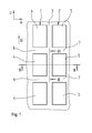
- the tread pattern is in a known manner - as in Fig. 1 shown - formed with a circumferentially U of the vehicle pneumatic tire over the entire circumference extended profile block row 1 and with a circumferentially U of the pneumatic vehicle tire over the entire circumference extended profile block row 2.
- the profile block row 1 and the profile block row 2 are spaced from each other by an extending over the circumference of the vehicle pneumatic tire and aligned in the circumferential direction U circumferential groove 3 in the axial direction A.
- the profile block row 1 is formed in a known manner from a plurality of circumferentially U behind the other and each formed by transverse grooves 6 spaced from each other profile block elements 4.
- the profile block row 2 is formed in a known manner from a plurality of in the circumferential direction U one behind the other and each spaced by transverse grooves 7 spaced apart profile block elements 5.
- the profile block elements 4 and 5 in the radial direction R to the outside of the bottom contact surface forming lateral surface 9 of the vehicle pneumatic tire are limited.
- the circumferential groove 3 is bounded radially inwardly with a over the entire circumference of the vehicle pneumatic tire extending and aligned in the circumferential direction U groove base 8 of known type.
- the circumferential groove 3 is the profile block row 4 out with a from the groove bottom 3 radially outward to the bottom contact surface forming the profile block elements 4 of the profile block row 1 radially outwardly limiting lateral surface 9 in the radial direction R outwardly extending groove wall 10 and the profile block row second out with a from the groove bottom 8 radially outward to the bottom contact surface forming, the profile block elements 5 of the profile block row 2 radially outwardly limiting lateral surface 9 in the radial direction R outwardly extending groove wall 11 limited.
- the groove wall 10 forms the circumferential groove 3 towards flank of the profile block elements 4 of the profile block row 1.
- the groove wall 11 forms the circumferential groove 3 towards flank of the profile block elements 5 of the profile block row 2.
- the circumferential groove 3 is with a starting from the lowest point of the groove bottom third formed to the surface contact surface forming lateral surface 9 measured profile depth P t .
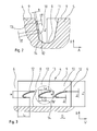
- FIGS. 2 and 3 are arranged in the groove wall 10jeweils with a radial distance from the groove bottom 8 and at a radial distance to the bottom contact surface forming lateral surface 9 on new tires along the extension of the profile block element 4 in the circumferential direction U one behind the other, several - in the illustrated embodiment three - from the otherwise substantially smooth surface of the groove wall 10 in the circumferential groove 3 extending into linear elevations formed 12 formed with a perpendicular to the smooth surface measured extension height B.
- the line-shaped elevations 12 extend over a in the radial direction R of Vehicle pneumatic tire measured radial extension height H.
- the line-shaped elevation 12 is formed in each case from a radially outer extension region 13 and from a radially inner extension region 14.
- the radially outer extension region 13 extends from the radially outer extension end of the linear elevation 12 radially inward in the direction of the radially inner extension end with a circumferential direction component opposite to the direction of rotation D during forward travel (and thus in the direction of rotation of the pneumatic vehicle tire when reversing) of the assembled vehicle tire in the operating state measured in the peripheral direction U extending length L a to the radially inner extending portion 14.
- the radially inner extending portion 14 extends from the radially inner extent of the end of the line-shaped projection 12 radially outward (toward the radially outer extent of the end with a circumferential component of direction opposite to the rotational direction D during forward travel and thus in the direction of rotation of the vehicle pneumatic tire when reversing) over an extension length L I to the radially outer extension portion and then goes into the outer Extension section 13 via.
- the line-shaped elevation 12 in this case has in the sectional plane with the groove wall 10 its maximum, in each case measured perpendicular to the extension direction of the linear elevation 12 width B 1 .
- the extension height B and the width B 1 of the linear elevation 12 are formed with 0.3 mm ⁇ B ⁇ 1.5 mm or with 0.3 mm ⁇ B 1 ⁇ 1.5 mm.
- the line-shaped elevations 12 are formed with 0.5 mm ⁇ B ⁇ 0.7 mm or with 0.5 mm ⁇ B 1 ⁇ 0.7 mm.
- B B 1 is selected.
- the radially outer extension region 13 is curved towards the radially inner extension region 14 and the radially inner extension region 14 is curved toward the radially outer extension region 13, ie the curvature of the radially outer extension region 13 is around one or more centers of curvature (R) on the radially outer extension portion 13 to the radially inner extension portion 14 side lying or lie side, and the radially inner extension portion 14 is about one or more centers of curvature (r) on the from the radially inner extension portion 14 to radially outer extension region 13 side lying lies or lie, curved.
- Fig. 4 is the tangent t a formed in the groove wall 10 in the radially outer extension end of the linear elevation 12 formed on the curvature of the radially outer extension portion 13 and the tangent t i formed in the radially inner extension end of the linear elevation 12 to the radially inner extension portion 14 in the groove wall 10 running marked.
- the two tangents t a and t i enclose an angle ⁇ with ⁇ ⁇ 90 °.
- the angle ⁇ is formed in the illustrated embodiments with 30 ° ⁇ ⁇ ⁇ 60 °.
- the angle ⁇ between the two tangents t i and t a bisecting straight line h is formed at its intersection with the linear elevation 12 including an angle ⁇ to the circumferential direction U with 80 °> ⁇ > 0 ° and extends in the direction of rotation D increasing its radial position in the pneumatic vehicle tire.
- ⁇ is formed with 45 ° > ⁇ > 5 °.
- ⁇ 10 ° is selected.
- the line-shaped elevation 12 forms with the radially outer extension portion 13 and the radially inner extension portion 14 a hook-shaped elevation 12, which when turning the vehicle pneumatic tire in the direction of rotation D in forward travel with the radially outer extension portion 13 hook-shaped in snow, mud or loose Substrate engages and introduces the material in the formed between the radially outer extension portion 13 and radially inner extension portion 14 type blade and contributes to increase the traction.
- the extension length L a of the radially outer extension portion 13 is set larger than the extension length L I of the radially inner extension portion 14.
- the extension length L a is (0.6 H) ⁇ L a ⁇ (0.15 H) and the extension length L i is formed with L a ⁇ L i ⁇ (0.1 H).
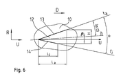
- Fig. 6 shows an alternative embodiment in which the line-shaped elevations 12 are formed with the contour of their linear course V-shaped, wherein the radially outer extension portion 13 the one rectilinear leg and the radially inner extension portion 14 the other, also rectilinear legs of the V-shaped Form forms.
- the tangent t a forms the radially outer leg 13 and the tangent t i the radially inner leg 14.
- FIG. 3 shows an embodiment in which in the circumferential direction U successively arranged linear elevations 12 each have a same extent height H in the radial direction R.
- At least some of the linear elevations 12 have mutually different extension heights H.
- the line-shaped elevations 12 are each formed in the same radial position of the tire in the groove wall 10.
- Fig. 5 shows an embodiment with first line-shaped elevations 12 with radially outer extension region 13 and with radially inner extension region 14 and with second linear elevations 12 'with radially outer extension region 13 and with radially inner extension region 14.
- a linear elevation element 12 and in an alternating sequence line-shaped elevation element 12 'formed in the circumferential direction U of the pneumatic vehicle tire arranged one behind the other.
- the linear elevations 12 'with their radial position in the pneumatic vehicle tire are each arranged radially below the radial position of the linear elevations 12.
- the circumferentially U successively arranged linear elevations 12 and 12 ' are each offset in their radial and circumferential position to each other, wherein the circumferentially successively arranged linear elevations 12 and 12 in its circumferential position with a measured in the circumferential direction U of the vehicle pneumatic tire extension length a are intersecting with a ⁇ L a .
- line-shaped elevations 12 are formed in one of the above-mentioned embodiments in the groove wall 11.
Landscapes
- Engineering & Computer Science (AREA)
- Mechanical Engineering (AREA)
- Tires In General (AREA)
Priority Applications (1)
| Application Number | Priority Date | Filing Date | Title |
|---|---|---|---|
| PL10188299T PL2332747T3 (pl) | 2009-12-09 | 2010-10-21 | Profil bieżnika opony pneumatycznej pojazdu |
Applications Claiming Priority (1)
| Application Number | Priority Date | Filing Date | Title |
|---|---|---|---|
| DE102009044846A DE102009044846A1 (de) | 2009-12-09 | 2009-12-09 | Laufstreifenprofil eines Fahrzeugluftreifens |
Publications (2)
| Publication Number | Publication Date |
|---|---|
| EP2332747A1 true EP2332747A1 (fr) | 2011-06-15 |
| EP2332747B1 EP2332747B1 (fr) | 2017-08-09 |
Family
ID=43733967
Family Applications (1)
| Application Number | Title | Priority Date | Filing Date |
|---|---|---|---|
| EP10188299.1A Active EP2332747B1 (fr) | 2009-12-09 | 2010-10-21 | Profil de bande de roulement d'un bandage pneumatique de véhicule |
Country Status (4)
| Country | Link |
|---|---|
| EP (1) | EP2332747B1 (fr) |
| DE (1) | DE102009044846A1 (fr) |
| ES (1) | ES2641185T3 (fr) |
| PL (1) | PL2332747T3 (fr) |
Citations (3)
| Publication number | Priority date | Publication date | Assignee | Title |
|---|---|---|---|---|
| US20010032691A1 (en) * | 2000-02-07 | 2001-10-25 | Bridgestone Corporation | Tire |
| JP2002019420A (ja) * | 2000-07-04 | 2002-01-23 | Bridgestone Corp | 空気入りタイヤ |
| US20070240801A1 (en) * | 2006-04-18 | 2007-10-18 | Toyo Tire & Rubber Co., Ltd. | Pneumatic Tire |
Family Cites Families (1)
| Publication number | Priority date | Publication date | Assignee | Title |
|---|---|---|---|---|
| IT1396282B1 (it) * | 2009-09-22 | 2012-11-16 | Bridgestone Corp | Pneumatico invernale con aumentata capacita' di trazione su fondi innevati. |
-
2009
- 2009-12-09 DE DE102009044846A patent/DE102009044846A1/de not_active Withdrawn
-
2010
- 2010-10-21 PL PL10188299T patent/PL2332747T3/pl unknown
- 2010-10-21 ES ES10188299.1T patent/ES2641185T3/es active Active
- 2010-10-21 EP EP10188299.1A patent/EP2332747B1/fr active Active
Patent Citations (3)
| Publication number | Priority date | Publication date | Assignee | Title |
|---|---|---|---|---|
| US20010032691A1 (en) * | 2000-02-07 | 2001-10-25 | Bridgestone Corporation | Tire |
| JP2002019420A (ja) * | 2000-07-04 | 2002-01-23 | Bridgestone Corp | 空気入りタイヤ |
| US20070240801A1 (en) * | 2006-04-18 | 2007-10-18 | Toyo Tire & Rubber Co., Ltd. | Pneumatic Tire |
Also Published As
| Publication number | Publication date |
|---|---|
| EP2332747B1 (fr) | 2017-08-09 |
| DE102009044846A1 (de) | 2011-06-16 |
| ES2641185T3 (es) | 2017-11-08 |
| PL2332747T3 (pl) | 2018-01-31 |
Similar Documents
| Publication | Publication Date | Title |
|---|---|---|
| DE102007061148A1 (de) | Fahrzeugluftreifen | |
| EP3300926B1 (fr) | Pneumatiques de véhicule | |
| WO2018158021A1 (fr) | Pneumatique de véhicule | |
| WO2011131381A1 (fr) | Pneu de véhicule | |
| EP3383669A1 (fr) | Pneumatique de véhicule | |
| WO2013064300A1 (fr) | Pneumatique de véhicule | |
| EP3421264B1 (fr) | Pneumatique de véhicule | |
| EP2455235B1 (fr) | Profil de bande de roulement d'un bandage pneumatique de véhicule | |
| EP2376297B1 (fr) | Bandage pneumatique pour véhicule | |
| EP3724006A1 (fr) | Pneumatiques pour véhicules utilitaires | |
| EP3620311B1 (fr) | Pneumatiques de véhicule | |
| EP3100872B1 (fr) | Pneumatiques de véhicule | |
| DE102008029659A1 (de) | Fahrzeugluftreifen | |
| EP2594416B1 (fr) | Zone lateral de bande de roulement | |
| EP2556971B1 (fr) | Pneus de véhicule | |
| EP3300925B1 (fr) | Pneumatiques de véhicule | |
| EP3313673B1 (fr) | Pneumatique de véhicule | |
| DE102008029660A1 (de) | Fahrzeugluftreifen | |
| EP2138328B1 (fr) | Pneus de véhicule | |
| EP2332747B1 (fr) | Profil de bande de roulement d'un bandage pneumatique de véhicule | |
| EP2388154B1 (fr) | Profil de bande de roulement d'un bandage pneumatique de véhicule | |
| EP3221160A1 (fr) | Pneumatique de véhicule | |
| DE102012110360A1 (de) | Fahrzeugluftreifen | |
| EP3686034B1 (fr) | Pneumatiques de véhicule | |
| EP3890994B1 (fr) | Profil de bande de roulement d'un pneu de véhicule |
Legal Events
| Date | Code | Title | Description |
|---|---|---|---|
| PUAI | Public reference made under article 153(3) epc to a published international application that has entered the european phase |
Free format text: ORIGINAL CODE: 0009012 |
|
| AK | Designated contracting states |
Kind code of ref document: A1 Designated state(s): AL AT BE BG CH CY CZ DE DK EE ES FI FR GB GR HR HU IE IS IT LI LT LU LV MC MK MT NL NO PL PT RO RS SE SI SK SM TR |
|
| AX | Request for extension of the european patent |
Extension state: BA ME |
|
| 17P | Request for examination filed |
Effective date: 20111215 |
|
| 17Q | First examination report despatched |
Effective date: 20130514 |
|
| GRAJ | Information related to disapproval of communication of intention to grant by the applicant or resumption of examination proceedings by the epo deleted |
Free format text: ORIGINAL CODE: EPIDOSDIGR1 |
|
| GRAP | Despatch of communication of intention to grant a patent |
Free format text: ORIGINAL CODE: EPIDOSNIGR1 |
|
| INTG | Intention to grant announced |
Effective date: 20170404 |
|
| GRAS | Grant fee paid |
Free format text: ORIGINAL CODE: EPIDOSNIGR3 |
|
| GRAA | (expected) grant |
Free format text: ORIGINAL CODE: 0009210 |
|
| AK | Designated contracting states |
Kind code of ref document: B1 Designated state(s): AL AT BE BG CH CY CZ DE DK EE ES FI FR GB GR HR HU IE IS IT LI LT LU LV MC MK MT NL NO PL PT RO RS SE SI SK SM TR |
|
| REG | Reference to a national code |
Ref country code: GB Ref legal event code: FG4D Free format text: NOT ENGLISH |
|
| REG | Reference to a national code |
Ref country code: CH Ref legal event code: EP Ref country code: AT Ref legal event code: REF Ref document number: 916393 Country of ref document: AT Kind code of ref document: T Effective date: 20170815 |
|
| REG | Reference to a national code |
Ref country code: IE Ref legal event code: FG4D Free format text: LANGUAGE OF EP DOCUMENT: GERMAN |
|
| REG | Reference to a national code |
Ref country code: DE Ref legal event code: R096 Ref document number: 502010013967 Country of ref document: DE |
|
| REG | Reference to a national code |
Ref country code: ES Ref legal event code: FG2A Ref document number: 2641185 Country of ref document: ES Kind code of ref document: T3 Effective date: 20171108 |
|
| REG | Reference to a national code |
Ref country code: NL Ref legal event code: FP |
|
| REG | Reference to a national code |
Ref country code: LT Ref legal event code: MG4D |
|
| PG25 | Lapsed in a contracting state [announced via postgrant information from national office to epo] |
Ref country code: NO Free format text: LAPSE BECAUSE OF FAILURE TO SUBMIT A TRANSLATION OF THE DESCRIPTION OR TO PAY THE FEE WITHIN THE PRESCRIBED TIME-LIMIT Effective date: 20171109 Ref country code: HR Free format text: LAPSE BECAUSE OF FAILURE TO SUBMIT A TRANSLATION OF THE DESCRIPTION OR TO PAY THE FEE WITHIN THE PRESCRIBED TIME-LIMIT Effective date: 20170809 Ref country code: LT Free format text: LAPSE BECAUSE OF FAILURE TO SUBMIT A TRANSLATION OF THE DESCRIPTION OR TO PAY THE FEE WITHIN THE PRESCRIBED TIME-LIMIT Effective date: 20170809 Ref country code: SE Free format text: LAPSE BECAUSE OF FAILURE TO SUBMIT A TRANSLATION OF THE DESCRIPTION OR TO PAY THE FEE WITHIN THE PRESCRIBED TIME-LIMIT Effective date: 20170809 Ref country code: FI Free format text: LAPSE BECAUSE OF FAILURE TO SUBMIT A TRANSLATION OF THE DESCRIPTION OR TO PAY THE FEE WITHIN THE PRESCRIBED TIME-LIMIT Effective date: 20170809 |
|
| PG25 | Lapsed in a contracting state [announced via postgrant information from national office to epo] |
Ref country code: RS Free format text: LAPSE BECAUSE OF FAILURE TO SUBMIT A TRANSLATION OF THE DESCRIPTION OR TO PAY THE FEE WITHIN THE PRESCRIBED TIME-LIMIT Effective date: 20170809 Ref country code: BG Free format text: LAPSE BECAUSE OF FAILURE TO SUBMIT A TRANSLATION OF THE DESCRIPTION OR TO PAY THE FEE WITHIN THE PRESCRIBED TIME-LIMIT Effective date: 20171109 Ref country code: GR Free format text: LAPSE BECAUSE OF FAILURE TO SUBMIT A TRANSLATION OF THE DESCRIPTION OR TO PAY THE FEE WITHIN THE PRESCRIBED TIME-LIMIT Effective date: 20171110 Ref country code: LV Free format text: LAPSE BECAUSE OF FAILURE TO SUBMIT A TRANSLATION OF THE DESCRIPTION OR TO PAY THE FEE WITHIN THE PRESCRIBED TIME-LIMIT Effective date: 20170809 Ref country code: IS Free format text: LAPSE BECAUSE OF FAILURE TO SUBMIT A TRANSLATION OF THE DESCRIPTION OR TO PAY THE FEE WITHIN THE PRESCRIBED TIME-LIMIT Effective date: 20171209 |
|
| PG25 | Lapsed in a contracting state [announced via postgrant information from national office to epo] |
Ref country code: DK Free format text: LAPSE BECAUSE OF FAILURE TO SUBMIT A TRANSLATION OF THE DESCRIPTION OR TO PAY THE FEE WITHIN THE PRESCRIBED TIME-LIMIT Effective date: 20170809 Ref country code: RO Free format text: LAPSE BECAUSE OF FAILURE TO SUBMIT A TRANSLATION OF THE DESCRIPTION OR TO PAY THE FEE WITHIN THE PRESCRIBED TIME-LIMIT Effective date: 20170809 Ref country code: CZ Free format text: LAPSE BECAUSE OF FAILURE TO SUBMIT A TRANSLATION OF THE DESCRIPTION OR TO PAY THE FEE WITHIN THE PRESCRIBED TIME-LIMIT Effective date: 20170809 |
|
| REG | Reference to a national code |
Ref country code: DE Ref legal event code: R097 Ref document number: 502010013967 Country of ref document: DE |
|
| PG25 | Lapsed in a contracting state [announced via postgrant information from national office to epo] |
Ref country code: SK Free format text: LAPSE BECAUSE OF FAILURE TO SUBMIT A TRANSLATION OF THE DESCRIPTION OR TO PAY THE FEE WITHIN THE PRESCRIBED TIME-LIMIT Effective date: 20170809 Ref country code: MC Free format text: LAPSE BECAUSE OF FAILURE TO SUBMIT A TRANSLATION OF THE DESCRIPTION OR TO PAY THE FEE WITHIN THE PRESCRIBED TIME-LIMIT Effective date: 20170809 Ref country code: SM Free format text: LAPSE BECAUSE OF FAILURE TO SUBMIT A TRANSLATION OF THE DESCRIPTION OR TO PAY THE FEE WITHIN THE PRESCRIBED TIME-LIMIT Effective date: 20170809 Ref country code: EE Free format text: LAPSE BECAUSE OF FAILURE TO SUBMIT A TRANSLATION OF THE DESCRIPTION OR TO PAY THE FEE WITHIN THE PRESCRIBED TIME-LIMIT Effective date: 20170809 Ref country code: IT Free format text: LAPSE BECAUSE OF FAILURE TO SUBMIT A TRANSLATION OF THE DESCRIPTION OR TO PAY THE FEE WITHIN THE PRESCRIBED TIME-LIMIT Effective date: 20170809 |
|
| REG | Reference to a national code |
Ref country code: CH Ref legal event code: PL |
|
| PLBE | No opposition filed within time limit |
Free format text: ORIGINAL CODE: 0009261 |
|
| STAA | Information on the status of an ep patent application or granted ep patent |
Free format text: STATUS: NO OPPOSITION FILED WITHIN TIME LIMIT |
|
| 26N | No opposition filed |
Effective date: 20180511 |
|
| GBPC | Gb: european patent ceased through non-payment of renewal fee |
Effective date: 20171109 |
|
| REG | Reference to a national code |
Ref country code: IE Ref legal event code: MM4A |
|
| REG | Reference to a national code |
Ref country code: FR Ref legal event code: ST Effective date: 20180629 |
|
| PG25 | Lapsed in a contracting state [announced via postgrant information from national office to epo] |
Ref country code: LU Free format text: LAPSE BECAUSE OF NON-PAYMENT OF DUE FEES Effective date: 20171021 Ref country code: CH Free format text: LAPSE BECAUSE OF NON-PAYMENT OF DUE FEES Effective date: 20171031 Ref country code: LI Free format text: LAPSE BECAUSE OF NON-PAYMENT OF DUE FEES Effective date: 20171031 |
|
| REG | Reference to a national code |
Ref country code: BE Ref legal event code: MM Effective date: 20171031 |
|
| PG25 | Lapsed in a contracting state [announced via postgrant information from national office to epo] |
Ref country code: BE Free format text: LAPSE BECAUSE OF NON-PAYMENT OF DUE FEES Effective date: 20171031 Ref country code: FR Free format text: LAPSE BECAUSE OF NON-PAYMENT OF DUE FEES Effective date: 20171031 Ref country code: SI Free format text: LAPSE BECAUSE OF FAILURE TO SUBMIT A TRANSLATION OF THE DESCRIPTION OR TO PAY THE FEE WITHIN THE PRESCRIBED TIME-LIMIT Effective date: 20170809 |
|
| PG25 | Lapsed in a contracting state [announced via postgrant information from national office to epo] |
Ref country code: MT Free format text: LAPSE BECAUSE OF FAILURE TO SUBMIT A TRANSLATION OF THE DESCRIPTION OR TO PAY THE FEE WITHIN THE PRESCRIBED TIME-LIMIT Effective date: 20170809 |
|
| PG25 | Lapsed in a contracting state [announced via postgrant information from national office to epo] |
Ref country code: IE Free format text: LAPSE BECAUSE OF NON-PAYMENT OF DUE FEES Effective date: 20171021 |
|
| PG25 | Lapsed in a contracting state [announced via postgrant information from national office to epo] |
Ref country code: GB Free format text: LAPSE BECAUSE OF NON-PAYMENT OF DUE FEES Effective date: 20171109 |
|
| REG | Reference to a national code |
Ref country code: AT Ref legal event code: MM01 Ref document number: 916393 Country of ref document: AT Kind code of ref document: T Effective date: 20171021 |
|
| PG25 | Lapsed in a contracting state [announced via postgrant information from national office to epo] |
Ref country code: AT Free format text: LAPSE BECAUSE OF NON-PAYMENT OF DUE FEES Effective date: 20171021 |
|
| PG25 | Lapsed in a contracting state [announced via postgrant information from national office to epo] |
Ref country code: HU Free format text: LAPSE BECAUSE OF FAILURE TO SUBMIT A TRANSLATION OF THE DESCRIPTION OR TO PAY THE FEE WITHIN THE PRESCRIBED TIME-LIMIT; INVALID AB INITIO Effective date: 20101021 |
|
| PG25 | Lapsed in a contracting state [announced via postgrant information from national office to epo] |
Ref country code: CY Free format text: LAPSE BECAUSE OF NON-PAYMENT OF DUE FEES Effective date: 20170809 |
|
| PG25 | Lapsed in a contracting state [announced via postgrant information from national office to epo] |
Ref country code: MK Free format text: LAPSE BECAUSE OF FAILURE TO SUBMIT A TRANSLATION OF THE DESCRIPTION OR TO PAY THE FEE WITHIN THE PRESCRIBED TIME-LIMIT Effective date: 20170809 |
|
| PG25 | Lapsed in a contracting state [announced via postgrant information from national office to epo] |
Ref country code: TR Free format text: LAPSE BECAUSE OF FAILURE TO SUBMIT A TRANSLATION OF THE DESCRIPTION OR TO PAY THE FEE WITHIN THE PRESCRIBED TIME-LIMIT Effective date: 20170809 |
|
| PG25 | Lapsed in a contracting state [announced via postgrant information from national office to epo] |
Ref country code: PT Free format text: LAPSE BECAUSE OF FAILURE TO SUBMIT A TRANSLATION OF THE DESCRIPTION OR TO PAY THE FEE WITHIN THE PRESCRIBED TIME-LIMIT Effective date: 20170809 |
|
| PG25 | Lapsed in a contracting state [announced via postgrant information from national office to epo] |
Ref country code: AL Free format text: LAPSE BECAUSE OF FAILURE TO SUBMIT A TRANSLATION OF THE DESCRIPTION OR TO PAY THE FEE WITHIN THE PRESCRIBED TIME-LIMIT Effective date: 20170809 |
|
| PGFP | Annual fee paid to national office [announced via postgrant information from national office to epo] |
Ref country code: NL Payment date: 20211020 Year of fee payment: 12 |
|
| PGFP | Annual fee paid to national office [announced via postgrant information from national office to epo] |
Ref country code: ES Payment date: 20211223 Year of fee payment: 12 Ref country code: DE Payment date: 20211031 Year of fee payment: 12 |
|
| PGFP | Annual fee paid to national office [announced via postgrant information from national office to epo] |
Ref country code: PL Payment date: 20211007 Year of fee payment: 12 |
|
| REG | Reference to a national code |
Ref country code: DE Ref legal event code: R119 Ref document number: 502010013967 Country of ref document: DE |
|
| REG | Reference to a national code |
Ref country code: NL Ref legal event code: MM Effective date: 20221101 |
|
| PG25 | Lapsed in a contracting state [announced via postgrant information from national office to epo] |
Ref country code: NL Free format text: LAPSE BECAUSE OF NON-PAYMENT OF DUE FEES Effective date: 20221101 Ref country code: DE Free format text: LAPSE BECAUSE OF NON-PAYMENT OF DUE FEES Effective date: 20230503 |
|
| REG | Reference to a national code |
Ref country code: ES Ref legal event code: FD2A Effective date: 20231201 |
|
| PG25 | Lapsed in a contracting state [announced via postgrant information from national office to epo] |
Ref country code: ES Free format text: LAPSE BECAUSE OF NON-PAYMENT OF DUE FEES Effective date: 20221022 |
|
| PG25 | Lapsed in a contracting state [announced via postgrant information from national office to epo] |
Ref country code: ES Free format text: LAPSE BECAUSE OF NON-PAYMENT OF DUE FEES Effective date: 20221022 |