EP2331802B1 - Anordnung zur messung einer kohlenwasserstoffkonzentration und brennkraftmaschine - Google Patents
Anordnung zur messung einer kohlenwasserstoffkonzentration und brennkraftmaschine Download PDFInfo
- Publication number
- EP2331802B1 EP2331802B1 EP09782483.3A EP09782483A EP2331802B1 EP 2331802 B1 EP2331802 B1 EP 2331802B1 EP 09782483 A EP09782483 A EP 09782483A EP 2331802 B1 EP2331802 B1 EP 2331802B1
- Authority
- EP
- European Patent Office
- Prior art keywords
- sensor
- line
- gas
- internal combustion
- combustion engine
- Prior art date
- Legal status (The legal status is an assumption and is not a legal conclusion. Google has not performed a legal analysis and makes no representation as to the accuracy of the status listed.)
- Active
Links
- 150000002430 hydrocarbons Chemical class 0.000 title claims description 74
- 229930195733 hydrocarbon Natural products 0.000 title claims description 73
- 239000004215 Carbon black (E152) Substances 0.000 title claims description 51
- 238000002485 combustion reaction Methods 0.000 title claims description 33
- 238000010438 heat treatment Methods 0.000 claims description 17
- 230000004888 barrier function Effects 0.000 claims description 4
- 230000001419 dependent effect Effects 0.000 claims description 4
- 238000004891 communication Methods 0.000 claims description 2
- 239000004065 semiconductor Substances 0.000 claims description 2
- 238000013022 venting Methods 0.000 claims 1
- 239000007789 gas Substances 0.000 description 43
- 239000000446 fuel Substances 0.000 description 20
- 239000002828 fuel tank Substances 0.000 description 9
- OKTJSMMVPCPJKN-UHFFFAOYSA-N Carbon Chemical compound [C] OKTJSMMVPCPJKN-UHFFFAOYSA-N 0.000 description 8
- 238000009423 ventilation Methods 0.000 description 6
- 239000007788 liquid Substances 0.000 description 4
- 238000011156 evaluation Methods 0.000 description 3
- 238000002347 injection Methods 0.000 description 3
- 239000007924 injection Substances 0.000 description 3
- 239000000523 sample Substances 0.000 description 3
- ATUOYWHBWRKTHZ-UHFFFAOYSA-N Propane Chemical compound CCC ATUOYWHBWRKTHZ-UHFFFAOYSA-N 0.000 description 2
- XUIMIQQOPSSXEZ-UHFFFAOYSA-N Silicon Chemical compound [Si] XUIMIQQOPSSXEZ-UHFFFAOYSA-N 0.000 description 2
- 239000003502 gasoline Substances 0.000 description 2
- 230000005484 gravity Effects 0.000 description 2
- 230000007257 malfunction Effects 0.000 description 2
- VNWKTOKETHGBQD-UHFFFAOYSA-N methane Chemical compound C VNWKTOKETHGBQD-UHFFFAOYSA-N 0.000 description 2
- ORQBXQOJMQIAOY-UHFFFAOYSA-N nobelium Chemical compound [No] ORQBXQOJMQIAOY-UHFFFAOYSA-N 0.000 description 2
- 229910052710 silicon Inorganic materials 0.000 description 2
- 239000010703 silicon Substances 0.000 description 2
- QVGXLLKOCUKJST-UHFFFAOYSA-N atomic oxygen Chemical compound [O] QVGXLLKOCUKJST-UHFFFAOYSA-N 0.000 description 1
- 239000001273 butane Substances 0.000 description 1
- 238000010276 construction Methods 0.000 description 1
- 238000011161 development Methods 0.000 description 1
- 230000018109 developmental process Effects 0.000 description 1
- 238000010586 diagram Methods 0.000 description 1
- 238000005516 engineering process Methods 0.000 description 1
- 230000008020 evaporation Effects 0.000 description 1
- 238000001704 evaporation Methods 0.000 description 1
- 239000000945 filler Substances 0.000 description 1
- 125000004435 hydrogen atom Chemical group [H]* 0.000 description 1
- 239000000203 mixture Substances 0.000 description 1
- IJDNQMDRQITEOD-UHFFFAOYSA-N n-butane Chemical compound CCCC IJDNQMDRQITEOD-UHFFFAOYSA-N 0.000 description 1
- OFBQJSOFQDEBGM-UHFFFAOYSA-N n-pentane Natural products CCCCC OFBQJSOFQDEBGM-UHFFFAOYSA-N 0.000 description 1
- 239000001301 oxygen Substances 0.000 description 1
- 229910052760 oxygen Inorganic materials 0.000 description 1
- 239000001294 propane Substances 0.000 description 1
- 230000008929 regeneration Effects 0.000 description 1
- 238000011069 regeneration method Methods 0.000 description 1
- 239000000758 substrate Substances 0.000 description 1
Images

Classifications
-
- F—MECHANICAL ENGINEERING; LIGHTING; HEATING; WEAPONS; BLASTING
- F02—COMBUSTION ENGINES; HOT-GAS OR COMBUSTION-PRODUCT ENGINE PLANTS
- F02D—CONTROLLING COMBUSTION ENGINES
- F02D41/00—Electrical control of supply of combustible mixture or its constituents
- F02D41/02—Circuit arrangements for generating control signals
- F02D41/14—Introducing closed-loop corrections
- F02D41/1438—Introducing closed-loop corrections using means for determining characteristics of the combustion gases; Sensors therefor
- F02D41/1444—Introducing closed-loop corrections using means for determining characteristics of the combustion gases; Sensors therefor characterised by the characteristics of the combustion gases
- F02D41/1459—Introducing closed-loop corrections using means for determining characteristics of the combustion gases; Sensors therefor characterised by the characteristics of the combustion gases the characteristics being a hydrocarbon content or concentration
-
- F—MECHANICAL ENGINEERING; LIGHTING; HEATING; WEAPONS; BLASTING
- F02—COMBUSTION ENGINES; HOT-GAS OR COMBUSTION-PRODUCT ENGINE PLANTS
- F02D—CONTROLLING COMBUSTION ENGINES
- F02D41/00—Electrical control of supply of combustible mixture or its constituents
- F02D41/0025—Controlling engines characterised by use of non-liquid fuels, pluralities of fuels, or non-fuel substances added to the combustible mixtures
- F02D41/003—Adding fuel vapours, e.g. drawn from engine fuel reservoir
- F02D41/0045—Estimating, calculating or determining the purging rate, amount, flow or concentration
-
- G—PHYSICS
- G01—MEASURING; TESTING
- G01N—INVESTIGATING OR ANALYSING MATERIALS BY DETERMINING THEIR CHEMICAL OR PHYSICAL PROPERTIES
- G01N27/00—Investigating or analysing materials by the use of electric, electrochemical, or magnetic means
- G01N27/02—Investigating or analysing materials by the use of electric, electrochemical, or magnetic means by investigating impedance
- G01N27/04—Investigating or analysing materials by the use of electric, electrochemical, or magnetic means by investigating impedance by investigating resistance
- G01N27/14—Investigating or analysing materials by the use of electric, electrochemical, or magnetic means by investigating impedance by investigating resistance of an electrically-heated body in dependence upon change of temperature
- G01N27/18—Investigating or analysing materials by the use of electric, electrochemical, or magnetic means by investigating impedance by investigating resistance of an electrically-heated body in dependence upon change of temperature caused by changes in the thermal conductivity of a surrounding material to be tested
Definitions
- the invention relates to an arrangement for measuring a hydrocarbon concentration and an internal combustion engine having such an arrangement.
- Exhaust gases can escape from the fuel tank of a motor vehicle in which, for example, gasoline is stored, and can be released from the fuel.
- Highly volatile hydrocarbons can detach from the fuel at high outside temperatures or as a result of vibrations in the fuel tank while driving and leave the fuel tank as gas.
- fuel tanks can be sealed gas-tight.
- the volatile hydrocarbons are then temporarily stored in a memory and can be supplied to the intake air of the internal combustion engine. If it is not known or not sufficiently well known how much hydrocarbons are dissolved in the intake air, it is not possible to control precisely how much less fuel has to be injected in order to achieve the best possible air / fuel ratio. This leads to an increased fuel consumption of the internal combustion engine and possibly also to poorer exhaust gas values.
- the US 5,535,614 describes a device for determining a fuel content in a tank ventilation system.
- the EP 1 094 306 A1 shows a sensor arrangement which has a plurality of temperature sensors and a heating element.
- An arrangement for measuring a hydrocarbon concentration of a gas stream in a line comprises at least one sensor for measuring a hydrocarbon concentration.
- the sensor is set back with respect to the line. With this arrangement, the sensor can measure the hydrocarbon content decoupled from the volume flow in the line.
- the hydrocarbon sensor is arranged in a sensor chamber which is coupled to the line.
- a gas-permeable element can be arranged between the line and the sensor chamber.
- the gas-permeable element can be gas-permeable such that the hydrocarbon concentration of the gas in the sensor chamber is dependent on that of the hydrocarbon concentration of the gas flow in the line.
- the hydrocarbon content in the sensor chamber determined by the sensor is representative of the hydrocarbon concentration of the gas flow in the line.
- the gas permeable element can be a barrier to flames. As a result, a fire caused by a malfunction on the sensor cannot spread in the line.
- the at least one sensor has at least one heating element for heating a gas stream and at least one first and one second temperature sensor, the at least one heating element being arranged between the first temperature sensor and the second temperature sensor.
- This structure enables the hydrocarbon content to be determined relatively precisely.
- the sensor comprises at least one semiconductor component, which in the at least one a sensor is integrated and is set up to send temperature-dependent signals.
- An internal combustion engine comprises an arrangement for measuring a hydrocarbon concentration of a gas stream in a line as described above. Because the hydrocarbon concentration of the gas stream is known, the internal combustion engine can be controlled relatively precisely.
- the line of the arrangement can be designed for pneumatic communication between a tank ventilation system and at least one cylinder of the internal combustion engine.
- the internal combustion engine can comprise a storage device for storing gaseous hydrocarbons, which is coupled to the line.
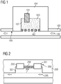
- Figure 1 shows a line 100 in which a gas stream 106 flows.
- a housing 104 is coupled to the line 100 and surrounds a sensor chamber 103.
- the housing 104 is coupled to the line 100 such that at least some of the gas that moves in the line can get into the sensor chamber 103.
- a sensor 101 which is set up to measure a hydrocarbon concentration, is arranged such that its sensitive areas are arranged in the sensor chamber or in contact with the hydrocarbons 107 can come.
- a gas-permeable element 102 is arranged on the sensor chamber 103 in the direction of the line 100.
- the line 100 which is part of a tank ventilation system of an internal combustion engine, for example, can be coupled at one end to a tank for gaseous hydrocarbons. Gas flows from this tank, for example, to an intake side of an internal combustion engine. The gas flows through the line 100 at a speed.
- the fact that the sensor 101 is arranged to be reset with respect to the line 100 means that the gas at the sensor has a lower flow speed or, if possible, no flow speed.
- the sensor can measure the hydrocarbon concentration decoupled from the flow rate of the gas stream 106.
- the sensor chamber 103 is surrounded by the housing 104 such that the chamber volume is so minimal that a change in the hydrocarbon concentration in the line 100 results in a change in the hydrocarbon concentration in the sensor chamber 103 as quickly as possible. With a smaller volume of the sensor chamber 103, the gas exchange takes place more quickly.
- the hydrocarbon concentration in the sensor chamber 103 is as equal as possible to the hydrocarbon concentration in the line 100.
- the gas-permeable element 102 is arranged between the sensor chamber 103 and the line 100.
- the gas-permeable element is a grid. At least part of the gas which is conducted in line 100 can reach the sensor chamber 103 through the grid. Gas that is in the sensor chamber 103 can enter the line 100.
- the grid 102 is designed such that it represents a barrier to flames. A malfunction, for example a short circuit on the sensor 101, can ignite hydrocarbons in the sensor chamber 103. The flames from this fire cannot overcome the grid 102. The fire cannot thus occur within line 100 spread and extinguishes as soon as all hydrocarbons 107 in the sensor chamber 103 are burned.
- the line 100 has an inner side 105 which, in operation, is oriented at the top in relation to gravity.
- the housing 104 or the sensor chamber 103 are arranged on this inner side 105.
- the sensor chamber 103 lies above the line 100, so that as far as possible no liquid can penetrate the chamber, for example due to gravity.
- the sensor 101 is arranged in the chamber such that a good gas exchange can take place between the sensor chamber 103 and the line 100 and the movement of the gas within the sensor chamber 103 on the sensor 101 is as small as possible.
- the senor 101 has a heating element for heating the gas and a temperature sensor.
- the sensor is integrated on a silicon chip.
- the hydrocarbon-containing gas is heated and the thermal conductivity of the gas can be determined on the basis of signals from the temperature sensor.
- the concentration of the hydrocarbons can be determined from this.
- the sensor can comprise an evaluation circuit and / or a digital-to-analog converter and / or further elements.
- the sensor comprises a component that operates in a temperature-dependent manner, for example a thermistor (negative temperature coefficient thermistor) or a diode.
- FIG. 14 shows a sensor 200 that is arranged reset with respect to a line 206.
- the sensor 200 has a temperature sensor 201 and a further temperature sensor 203, which are each arranged on one side of a heating element 202.
- the sensor 200 is configured to measure the concentration of hydrocarbon in the gas 205.
- the sensor 200 is arranged in a sensor chamber 207, which is decoupled from the line by a grid 204. In the sensor chamber 207 the gas has the lowest possible flow rate.
- the sensor 200 is integrated on a silicon substrate, for example, and can include further components, for example an evaluation circuit, an analog-digital converter or a circuit for temperature compensation.
- the temperature sensor 201 and the temperature sensor 203 can each have a plurality of temperature sensors for measuring a temperature.
- the temperature sensors 201 and 203 and the heating element 202 are arranged on one level.
- the temperature sensor 201 measures a first temperature and the temperature sensor 203 measures a further temperature.
- the respective level of the temperatures results from the heating of the gas by the heating element 202.
- the gas is heated differently with a constant heating power.
- the temperature that is measured by sensor 201 and the further temperature that is measured by temperature sensor 203 can be added for evaluation.
- this value of the added temperatures is representative of the hydrocarbon concentration of the gas in the sensor chamber 207. Because the gas exchange between the sensor chamber 207 and the line 206 is as good as possible, this value is also representative of the hydrocarbon concentration of the gas 205 .
- FIG. 3 shows an internal combustion engine 300.
- the internal combustion engine 300 has a fuel tank 304, an internal combustion engine 312 and a tank ventilation system 318.
- Fuel 305 for example gasoline, is stored in the fuel tank 304.
- Gaseous hydrocarbons 307 which are released from the liquid fuel 305, are supplied to the internal combustion engine 312 via the tank ventilation system.
- the tank ventilation system 318 has a line 308 that connects to the fuel tank 304 and a hydrocarbon tank 306 is coupled. Gaseous hydrogens can be directed into the hydrocarbon tank 306 from the fuel tank 304.
- the hydrocarbon tank is coupled to the internal combustion engine 312 via a line 309, in particular to the intake tract of the internal combustion engine.
- a sensor 301 for measuring a hydrocarbon concentration is reset on line 309.
- a sensor chamber 311, in which the sensor 301 is arranged, is coupled to the line 309.
- a grid, which in particular represents a barrier to flames, can be arranged between the sensor chamber 311 and the line 309. Further sensors for measuring a hydrocarbon concentration can also be arranged.
- sensors 308 are arranged on the line and are configured to measure a hydrocarbon content of a gas.
- the sensor 301 is coupled to a motor controller 303 via an electrical line 310.
- the engine control 303 can evaluate signals from the sensor 301 and determine the hydrocarbon concentration in the sensor chamber.
- the gas flow through line 309 may be controlled by a valve 302 coupled to line 309.
- the valve 302 is coupled to the engine control 303 via an electrical line.
- the engine controller 303 can evaluate the signals from the hydrocarbon sensors and control valves.
- the fuel 305 can be fed via a fuel delivery unit via fuel lines to the internal combustion engine 312, where it is injected via at least one injection valve 315 into the intake tract of the internal combustion engine or into at least one cylinder 317 and is combusted in the internal combustion engine.
- the exhaust gases from the combustion process are conveyed away from the engine by an exhaust system.
- a lambda probe 316 is arranged in the exhaust line, which has a ratio can determine from air to fuel. To do this, the lambda probe measures the residual oxygen content in the exhaust gas.
- Hydrocarbons for example methane, butane or propane, evaporate from fuel 305.
- the different hydrocarbon chains have different evaporation temperatures, so that different hydrocarbons are released from the liquid fuel 305 depending on the outside temperature. The higher the outside temperature and thus the temperature of the fuel 305, the more hydrocarbons go into the gas phase.
- the tank 304 in which the fuel 305 is stored, is gas-tight, so that, if possible, no gas can escape from the tank 304 unintentionally.
- the tank cap closes a filler neck of the fuel tank as gas-tight as possible.
- the hydrocarbon-containing gas mixture that forms in the tank 304 is fed into the hydrocarbon tank 306 via the line 308.
- the hydrocarbon tank may contain an activated carbon storage element.
- the evaporated hydrocarbons are absorbed by the activated carbon, stored and released again when necessary.
- the hydrocarbon tank When the hydrocarbon tank has taken up a certain amount of hydrocarbons, it can be emptied via line 309.
- air is blown into the hydrocarbon tank from outside via a valve 313, which absorbs the hydrocarbons.
- the hydrocarbon-containing air can be used as intake air for the internal combustion engine 312 and thus contribute to combustion in the engine.
- the hydrocarbon content of the supplied air is measured via the hydrocarbon sensors.
- the mass flow can be determined by the engine control 303 by stored models which measure the mass flow simulate line 309 or valve 302. It can also be determined directly using one or more air mass sensors, but it can also be derived in part from other measured variables using appropriate models.
- the engine controller 303 evaluates the signals from the sensor 301, so that the concentration of hydrocarbons in the gas stream through the line 309 is known.
- the mass flow is known from the characteristic diagrams that are stored in the engine control 303. It is thus known how much energy is supplied to the internal combustion engine 312 in the form of gaseous hydrocarbons.
- the engine control 303 controls actuators accordingly, so that the ratio of liquid fuel to gaseous hydrocarbons is as optimal as possible and the fuel consumption is therefore as low as possible.
- the exhaust gases are also as low in emissions as possible.
- the activated carbon filter can be emptied relatively quickly since the control works relatively quickly, in particular in comparison with a control which is based on data from the lambda probe 316.
- the amount of fuel that is injected into the internal combustion engine via the injection valves 315 is controlled not only on the basis of the data from the lambda sensor, but also directly through the data that the engine control 303 determines with the aid of the hydrocarbon sensors.
- the amount of gas flowing through line 309 need not be limited, which in particular leads to relatively short regeneration times of the hydrocarbon tank 306. This can be the case with vehicles with hybrid drive or start-stop technology, in which one shorter engine runtime makes a quick emptying of the activated carbon filter necessary.
Landscapes
- Engineering & Computer Science (AREA)
- Chemical & Material Sciences (AREA)
- Combustion & Propulsion (AREA)
- Mechanical Engineering (AREA)
- General Engineering & Computer Science (AREA)
- Health & Medical Sciences (AREA)
- Electrochemistry (AREA)
- Physics & Mathematics (AREA)
- Chemical Kinetics & Catalysis (AREA)
- Life Sciences & Earth Sciences (AREA)
- Analytical Chemistry (AREA)
- Biochemistry (AREA)
- General Health & Medical Sciences (AREA)
- General Physics & Mathematics (AREA)
- Immunology (AREA)
- Pathology (AREA)
- Supplying Secondary Fuel Or The Like To Fuel, Air Or Fuel-Air Mixtures (AREA)
Description
- Die Erfindung betrifft eine Anordnung zur Messung einer Kohlenwasserstoffkonzentration und eine Brennkraftmaschine, die eine solche Anordnung aufweist.
- Aus dem Kraftstofftank eines Kraftfahrzeugs, in dem beispielsweise Benzin gelagert ist, können Abgase austreten, die sich aus dem Kraftstoff lösen. Leicht flüchtige Kohlenwasserstoffe können sich bei hohen Außentemperaturen oder durch Erschütterungen des Kraftstofftanks während der Fahrt aus dem Kraftstoff lösen und als Gas den Kraftstofftank verlassen. Um dem entgegenzuwirken, können Kraftstofftanks gasdicht abgeschlossen werden. Die flüchtigen Kohlenwasserstoffe werden dann in einem Speicher zwischengespeichert und können der Ansaugluft des Verbrennungsmotors zugeführt werden. Wenn nicht oder nicht ausreichend genau bekannt ist, wie viel Kohlenwasserstoffe in der Ansaugluft gelöst sind, kann nicht genau genug gesteuert werden, wie viel weniger Kraftstoff eingespritzt werden muss, um ein möglichst optimales Kraftstoff-/Luft-Verhältnis zu erreichen. Dies führt zu einem erhöhten Kraftstoffverbrauch des Verbrennungsmotors und gegebenenfalls auch zu schlechteren Abgaswerten.
- Die
US 5,535,614 beschreibt eine Vorrichtung zur Ermittlung eines Kraftstoffgehalts in einem Tankentlüftungssystem. - Die
EP 1 094 306 A1 zeigt eine Sensoranordnung, die mehrere Temperatursensoren und ein Heizelement aufweist. - Es ist eine Aufgabe der Erfindung, eine Anordnung zur Messung einer Kohlenwasserstoffkonzentration sowie eine Brennkraftmaschine anzugeben, die einen präzisen Betrieb einer Brennkraftmaschine ermöglichen.
- Diese Aufgabe wird gelöst durch eine Anordnung mit dem Merkmal des Anspruchs 1 beziehungsweise einer Brennkraftmaschine mit den Merkmalen des Anspruchs 9.
- Eine Anordnung zur Messung einer Kohlenwasserstoffkonzentration eines Gasstroms in einer Leitung umfasst mindestens einen Sensor zur Messung einer Kohlenwasserstoffkonzentration. Der Sensor ist in Bezug auf die Leitung zurückgesetzt angeordnet. Durch diese Anordnung kann der Sensor den Kohlenwasserstoffgehalt entkoppelt von dem Volumenstrom in der Leitung messen.
- Erfindungsgemäß ist der Kohlenwasserstoffsensor in einer Sensorkammer angeordnet, die mit der Leitung gekoppelt ist. Zwischen der Leitung und der Sensorkammer kann ein gasdurchlässiges Element angeordnet sein. So ist ein möglichst einfacher Aufbau eines zurückgesetzt angeordneten Sensors realisiert.
- Das gasdurchlässige Element kann so gasdurchlässig sein, dass die Kohlenwasserstoffkonzentration des Gases in der Sensorkammer abhängig von der der Kohlenwasserstoffkonzentration des Gasstroms in der Leitung ist. Dadurch ist der von dem Sensor ermittelte Kohlenwasserstoffgehalt in der Sensorkammer repräsentativ für die Kohlenwasserstoffkonzentration des Gasstroms in der Leitung.
- Das gasdurchlässige Element kann eine Barriere für Flammen sein. Dadurch kann sich ein Feuer, das durch eine Fehlfunktion an dem Sensor entsteht, nicht in der Leitung ausbreiten.
- Der mindestens eine Sensor weist mindestens ein Heizelement zum Aufheizen eines Gasstroms und mindestens einen ersten und einen zweiten Temperatursensor auf, wobei das mindestens eine Heizelement zwischen dem ersten Temperatursensor und dem zweiten Temperatursensor angeordnet ist. Durch diesen Aufbau kann der Kohlenwasserstoffgehalt relativ genau ermittelt werden. Der Sensor umfasst in einem weiteren Ausführungsbeispiel mindestens ein Halbleiterbauelement, das in dem mindestens einen Sensor integriert ist und eingerichtet ist, temperaturabhängige Signale zu senden.
- Eine Brennkraftmaschine umfasst eine Anordnung zur Messung einer Kohlenwasserstoffkonzentration eines Gasstroms in einer Leitung wie oben beschrieben. Dadurch, dass die Kohlenwasserstoffkonzentration des Gasstroms bekannt ist, kann die Brennkraftmaschine relativ präzise gesteuert werden. Die Leitung der Anordnung kann zur pneumatischen Kommunikation zwischen einem Tankentlüftungssystem und mindestens einen Zylinder der Brennkraftmaschine ausgebildet sein. Die Brennkraftmaschine kann einen Speicher zur Speicherung von gasförmigen Kohlenwasserstoffen umfassen, der mit der Leitung gekoppelt ist.
- Weitere Merkmale, Vorteile und Weiterbildungen ergeben sich aus den nachfolgenden in Verbindung mit den
Figuren 1 bis 3 erläuterten Beispielen. Es zeigen: - Figur 1
- eine schematische Anordnung eines Sensors in einer Sensorkammer,
- Figur 2
- eine schematische Darstellung eines Sensors gemäß einer Ausführungsform,
- Figur 3
- eine schematische Darstellung einer Brennkraftmaschine.
-
Figur 1 zeigt eine Leitung 100, in der ein Gasstrom 106 strömt. Mit der Leitung 100 ist ein Gehäuse 104 gekoppelt, das eine Sensorkammer 103 umgibt. Das Gehäuse 104 ist mit der Leitung 100 so gekoppelt, dass das Gas, das sich in der Leitung bewegt, zumindest zu einem Teil in die Sensorkammer 103 gelangen kann. In der Sensorkammer befinden sich Kohlenwasserstoffe 107. Ein Sensor 101, der eingerichtet ist eine Kohlenwasserstoffkonzentration zu messen, ist so angeordnet, dass seine sensiblen Bereiche in der Sensorkammer angeordnet sind beziehungsweise mit den Kohlenwasserstoffen 107 in Kontakt kommen können. An der Sensorkammer 103 ist in Richtung der Leitung 100 ein gasdurchlässiges Element 102 angeordnet. - Die Leitung 100, die beispielsweise Teil eines Tankentlüftungssystems einer Brennkraftmaschine ist, kann mit einem Ende mit einem Tank für gasförmige Kohlenwasserstoffe gekoppelt sein. Aus diesem Tank strömt Gas beispielsweise zu einer Ansaugseite eines Verbrennungsmotors. Das Gas strömt mit einer Geschwindigkeit durch die Leitung 100. Dadurch, dass der Sensor 101 im Bezug auf die Leitung 100 zurückgesetzt angeordnet ist, weist das Gas an dem Sensor eine geringere oder möglichst keine Strömungsgeschwindigkeit auf. Der Sensor kann die Kohlenwasserstoffkonzentration entkoppelt von der Strömungsgeschwindigkeit des Gasstroms 106 messen.
- Die Sensorkammer 103 wird von dem Gehäuse 104 so umgeben, dass das Kammervolumen so minimal ist, dass eine Änderung der Kohlenwasserstoffkonzentration in der Leitung 100 möglichst schnell eine Änderung der Kohlenwasserstoffkonzentration in der Sensorkammer 103 zur Folge hat. Bei einem kleineren Volumen der Sensorkammer 103 findet der Gasaustausch schneller statt. Die Kohlenwasserstoffkonzentration in der Sensorkammer 103 ist möglichst gleich der Kohlenwasserstoffkonzentration in der Leitung 100.
- Zwischen der Sensorkammer 103 und der Leitung 100 ist das gasdurchlässige Element 102 angeordnet. Das gasdurchlässige Element ist in der gezeigten Ausführungsform ein Gitter. Durch das Gitter kann zumindest ein Teil des Gases, das in der Leitung 100 geführt wird, in die Sensorkammer 103 gelangen. Gas, das in der Sensorkammer 103 ist, kann in die Leitung 100 gelangen. Das Gitter 102 ist so ausgebildet, dass es eine Barriere für Flammen darstellt. Durch eine Fehlfunktion beispielsweise einen Kurzschluss an dem Sensor 101 können in der Sensorkammer 103 Kohlenwasserstoffe entzündet werden. Die Flammen dieses Brandes können das Gitter 102 nicht überwinden. Der Brand kann sich so nicht innerhalb der Leitung 100 ausbreiten und erlischt, sobald alle Kohlenwasserstoffe 107 in der Sensorkammer 103 verbrannt sind.
- Die Leitung 100 weist in Bezug auf die Umgebung eine Innenseite 105 auf, die in Betrieb in Bezug auf die Schwerkraft oben liegend orientiert ist. Das Gehäuse 104 beziehungsweise die Sensorkammer 103 sind an dieser Innenseite 105 angeordnet. Die Sensorkammer 103 liegt oberhalb der Leitung 100, so dass möglichst keine Flüssigkeit beispielsweise durch die Schwerkraft in die Kammer eindringen kann. Der Sensor 101 ist in der Kammer so angeordnet, dass ein guter Gasaustausch zwischen der Sensorkammer 103 und der Leitung 100 stattfinden kann und die Bewegung des Gases innerhalb der Sensorkammer 103 an dem Sensor 101 möglichst gering ist.
- Der Sensor 101 weist in einem vom Erfindungsgegenstand abweichenden Beispiel ein Heizelement zum Aufheizen des Gases und einen Temperatursensor auf. Beispielsweise ist der Sensor auf einem Siliziumchip integriert. Das kohlenwasserstoffhaltige Gas wird aufgeheizt und anhand von Signalen des Temperatursensors kann die Wärmeleitfähigkeit des Gases ermittelt werden. Daraus kann die Konzentration der Kohlenwasserstoffe ermittelt werden. Der Sensor kann eine Auswerteschaltung und/oder einen Digital-Analog-Wandler und/oder weitere Elemente umfassen. In einer weiteren Ausführungsform umfasst der Sensor ein Bauelement, das temperaturabhängig arbeitet, beispielsweise einen Heißleiter (Negative Temperature Coefficient Thermistor) oder eine Diode.
-
Figur 2 zeigt einen Sensor 200, der in Bezug auf eine Leitung 206 zurückgesetzt angeordnet ist. Der Sensor 200 weist einen Temperatursensor 201 und einen weiteren Temperatursensor 203 auf, die jeweils auf einer Seite eines Heizelements 202 angeordnet sind. Der Sensor 200 ist eingerichtet, die Konzentration von Kohlenwasserstoff in dem Gas 205 zu messen. Der Sensor 200 ist in einer Sensorkammer 207 angeordnet, die von der Leitung durch ein Gitter 204 entkoppelt ist. In der Sensorkammer 207 weist das Gas eine möglichst geringe Strömungsgeschwindigkeit auf. - Der Sensor 200 ist beispielsweise auf einem Siliziumsubstrat integriert und kann weitere Bauelemente umfassen, beispielsweise eine Auswerteschaltung, einen Analog-Digital-Wandler oder eine Schaltung zur Temperaturkompensation. Der Temperatursensor 201 und der Temperatursensor 203 können jeweils mehrere Temperaturfühler zum Messen einer Temperatur aufweisen. Die Temperatursensoren 201 und 203 und das Heizelement 202 sind auf einer Ebene angeordnet.
- Der Temperatursensor 201 misst eine erste Temperatur und der Temperatursensor 203 misst eine weitere Temperatur. Die jeweilige Höhe der Temperaturen ergibt sich aus dem Aufheizen des Gases durch das Heizelement 202. Abhängig von der Kohlenwasserstoffkonzentration wird das Gas bei konstanter Heizleistung unterschiedlich erhitzt. Die Temperatur, die von dem Sensor 201 gemessen wird und die weitere Temperatur, die von dem Temperatursensor 203 gemessen wird, können zur Auswertung addiert werden. Dieser Wert der addierten Temperaturen ist abhängig von einer bekannten Heizleistung repräsentativ für die Kohlenwasserstoffkonzentration des Gases in der Sensorkammer 207. Dadurch dass ein möglichst guter Gasaustausch zwischen der Sensorkammer 207 und der Leitung 206 stattfinden kann, ist dieser Wert auch repräsentativ für die Kohlenwasserstoffkonzentration des Gases 205.
-
Figur 3 zeigt eine Brennkraftmaschine 300. Die Brennkraftmaschine 300 weist einen Kraftstofftank 304, einen Verbrennungsmotor 312 sowie ein Tankentlüftungssystem 318 auf. In dem Kraftstofftank 304 ist Kraftstoff 305 gelagert, beispielsweise Benzin. Gasförmige Kohlenwasserstoffe 307, die sich aus dem flüssigen Kraftstoff 305 lösen, werden über das Tankentlüftungssystem dem Verbrennungsmotor 312 zugeführt. Das Tankentlüftungssystem 318 weist eine Leitung 308 auf, die mit dem Kraftstofftank 304 und einem Kohlenwasserstofftank 306 gekoppelt ist. Aus dem Kraftstofftank 304 können gasförmige Wasserstoffe in den Kohlenwasserstofftank 306 geleitet werden. Der Kohlenwasserstofftank ist über eine Leitung 309 mit dem Verbrennungsmotor 312 gekoppelt, insbesondere mit dem Ansaugtrakt des Verbrennungsmotors. - Ein Sensor 301 zur Messung einer Kohlenwasserstoffkonzentration ist zurückgesetzt an der Leitung 309 angeordnet. Eine Sensorkammer 311, in der der Sensor 301 angeordnet ist, ist mit der Leitung 309 gekoppelt. Ein Gitter, das insbesondere eine Barriere für Flammen darstellt, kann zwischen der Sensorkammer 311 und der Leitung 309 angeordnet sein. Es können auch weitere Sensoren zur Messung einer Kohlenwasserstoffkonzentration angeordnet sein. Beispielsweise sind an der Leitung 308 Sensoren angeordnet, die eingerichtet sind, einen Kohlenwasserstoffgehalt eines Gases zu messen. Der Sensor 301 ist über eine elektrische Leitung 310 mit einer Motorsteuerung 303 gekoppelt. Die Motorsteuerung 303 kann Signale des Sensors 301 auswerten und die Kohlenwasserstoffkonzentration in der Sensorkammer ermitteln.
- Der Gasstrom durch die Leitung 309 kann von einem Ventil 302 gesteuert werden, das mit der Leitung 309 gekoppelt ist. Das Ventil 302 ist über eine elektrische Leitung mit der Motorsteuerung 303 gekoppelt. Die Motorsteuerung 303 kann die Signale der Kohlenwasserstoffsensoren auswerten und Ventile steuern.
- Der Kraftstoff 305 kann über eine Kraftstofffördereinheit über Kraftstoffleitungen zum Verbrennungsmotor 312 geführt werden, wo er über mindestens ein Einspritzventil 315 in den Ansaugtrakt des Verbrennungsmotors oder in mindestens einen Zylinder 317 eingespritzt wird und im Verbrennungsmotor zur Verbrennung kommt. Die Abgase des Verbrennungsprozesses werden durch einen Abgasstrang vom Motor weg gefördert. Im Abgasstrang ist eine Lambdasonde 316 angeordnet, die ein Verhältnis von Luft zu Kraftstoff bestimmen kann. Dazu misst die Lambdasonde den Restsauerstoffgehalt im Abgas.
- Aus dem Kraftstoff 305 verflüchtigen sich Kohlenwasserstoffe, beispielsweise Methan, Butan oder Propan. Die verschiedenen Kohlenwasserstoffketten weisen unterschiedliche Verdampfungstemperaturen auf, so dass abhängig von der Außentemperatur unterschiedliche Kohlenwasserstoffe aus dem flüssigen Kraftstoff 305 ausgelöst werden. Je höher die Außentemperatur und damit die Temperatur des Kraftstoffs 305 desto mehr Kohlenwasserstoffe gehen in die Gasphase über. Der Tank 304, in dem der Kraftstoff 305 gelagert ist, ist gasdicht ausgeführt, so dass möglichst kein Gas ungewollt aus dem Tank 304 entweichen kann. Der Tankdeckel schließt einen Einfüllstutzen des Kraftstofftanks dazu möglichst gasdicht ab. Das kohlenwasserstoffhaltige Gasgemisch, das sich in dem Tank 304 bildet, wird über die Leitung 308 in den Kohlenwasserstofftank 306 geführt.
- Der Kohlenwasserstofftank kann ein Aktivkohlespeicherelement enthalten. Die ausgedampften Kohlenwasserstoffe werden von der Aktivkohle aufgenommen, gespeichert und bei Bedarf wieder abgegeben. Wenn der Kohlenwasserstofftank eine gewisse Menge an Kohlenwasserstoffen aufgenommen hat, kann er über die Leitung 309 entleert werden. Dazu wird in den Kohlenwasserstofftank von außen über ein Ventil 313 Luft eingeblasen, die die Kohlenwasserstoffe aufnimmt. Die kohlenwasserstoffhaltige Luft kann als Ansaugluft für den Verbrennungsmotor 312 verwendet werden und damit zur Verbrennung im Motor beitragen.
- Da durch die Kohlenwasserstoffe in der Ansaugluft dem Verbrennungsmotor eine gewisse Energiemenge zugeführt wird, kann über die Einspritzventile 315 entsprechend weniger Kraftstoff eingespritzt werden. Zur Steuerung dieses Verhältnisses wird der Kohlenwasserstoffgehalt der zugeführten Luft über die Kohlenwasserstoffsensoren gemessen.
- Dadurch, dass der Kohlenwasserstoffsensor 301 in der Sensorkammer 311 zurückgesetzt zur Leitung 309 angeordnet ist, misst dieser lediglich die Kohlenwasserstoffkonzentration des Gases entkoppelt von dem Massenstrom durch die Leitung 309. Der Massenstrom kann von der Motorsteuerung 303 durch gespeicherte Modelle ermittelt werden, die den Massenstrom durch die Leitung 309 beziehungsweise das Ventil 302 simulieren. Er kann auch direkt mittels eines oder mehrerer Luftmassensensoren ermittelt werden, er kann aber auch teilweise von anderen Messgrößen mittels entsprechenden Modellen abgeleitet werden.
- Die Motorsteuerung 303 wertet die Signale des Sensors 301 aus, so dass die Konzentration an Kohlenwasserstoffen des Gasstroms durch die Leitung 309 bekannt ist. Durch die Kennfelder, die in der Motorsteuerung 303 gespeichert sind, ist der Massenstrom bekannt. Damit ist bekannt, wie viel Energie in Form von gasförmigen Kohlenwasserstoffen dem Verbrennungsmotor 312 zugeführt wird. Die Motorsteuerung 303 steuert Stellglieder entsprechend, so dass das das Verhältnis von flüssigem Kraftstoff zu gasförmigen Kohlenwasserstoffen möglichst optimal ist und dadurch der Kraftstoffverbrauch möglich gering ist. Die Abgase sind dadurch ebenfalls möglichst emissionsarm.
- Der Aktivkohlefilter kann relativ schnell entleert werden, da die Steuerung relativ schnell arbeitet, insbesondere im Vergleich mit einer Steuerung, die auf Daten der Lambdasonde 316 beruht. Die Menge an Kraftstoff, die über die Einspritzventile 315 in den Verbrennungsmotor eingespritzt wird, wird nicht nur auf Grundlage der Daten der Lambdasonde gesteuert, sondern direkt durch die Daten, die die Motorsteuerung 303 mit Hilfe der Kohlenwasserstoffsensoren bestimmt. Die Menge an Gas, die durch die Leitung 309 strömt, muss nicht begrenzt werden, was insbesondere zu relativ kurzen Regenerierzeiten des Kohlenwasserstofftanks 306 führt. Dies kann bei Fahrzeugen mit Hybridantrieb oder Start-Stopp-Technik, in denen eine geringere Motorlaufzeit ein schnelles Entleeren des Aktivkohlefilters notwendig macht, von Vorteil sein.
Claims (9)
- Anordnung zur Messung einer Kohlenwasserstoffkonzentration eines Gasstroms in einer Leitung (100), umfassend:- mindestens einen Sensor (101; 200) zur Messung einer Kohlenwasserstoffkonzentration, wobei der Sensor (101; 200) mindestens ein Heizelement (202) zum Aufheizen eines Gasstroms und mindestens einen Temperatursensor (203) und mindestens einen weiteren Temperatursensor (201) aufweist, und bei der das mindestens eine Heizelement (202) zwischen dem Temperatursensor (201) und dem weiteren Temperatursensor (203) angeordnet ist, wobei der mindestens eine Sensor (101; 200) eine Auswerteschaltung umfasst, die dazu eingerichtet ist, die Summe der Temperaturen des mindestens einen Temperatursensors (203) und des mindestens einen weiteren Temperatursensors (201) zu ermitteln, dadurch gekennzeichnet, dass der mindestens eine Sensor in Bezug auf die Leitung (100) zurückgesetzt angeordnet ist, wobei der Sensor (101) in einer Sensorkammer (103, 207) angeordnet ist, und wobei das Gas in der Sensorkammer (103, 207) möglichst keine Strömungsgeschwindigkeit aufweist, und dass die Auswerteschaltung dazu eingerichtet ist, die Kohlenwasserstoffkonzentration in Abhängigkeit von einer Heizleistung des mindestens einen Heizelements (202) und der ermittelten Summe zu ermitteln.
- Anordnung nach Anspruch 1, bei der der Kohlenwasserstoffsensor (101) in einer Sensorkammer (103) angeordnet ist, die mit der Leitung (100) gekoppelt ist.
- Anordnung nach Anspruch 2, die ein gasdurchlässiges Element (102) umfasst, das zwischen der Leitung (101) und Sensorkammer (103) angeordnet ist.
- Anordnung nach Anspruch 3, bei der das gasdurchlässige Element (102) so gasdurchlässig ist, dass die Kohlenwasserstoffkonzentration des Gases in der Sensorkammer (103) abhängig von der der Kohlenwasserstoffkonzentration des Gasstroms in der Leitung (100) ist.
- Anordnung nach Anspruch 3 oder 4, bei der das gasdurchlässige Element (102) eine Barriere für Flammen ist.
- Anordnung nach einem der Ansprüche 1 bis 5, bei der der mindestens eine Sensor (101) mindestens ein Halbleiterbauelement aufweist, das in dem mindestens einen Sensor (101) integriert ist und eingerichtet ist temperaturabhängige Signale zu senden.
- Brennkraftmaschine, umfassend eine Anordnung nach einem der Ansprüche 1 bis 6.
- Brennkraftmaschine nach Anspruch 7, bei der die Leitung (309) ausgebildet ist zur pneumatischen Kommunikation zwischen einem Tankentlüftungssystem (318) und mindestens einem Zylinder (317) der Brennkraftmaschine.
- Brennkraftmaschine nach Anspruch 8, die einen Speicher (306) zur Speicherung von gasförmigen Kohlenwasserstoffen umfasst, der mit der Leitung (309) gekoppelt ist.
Applications Claiming Priority (2)
| Application Number | Priority Date | Filing Date | Title |
|---|---|---|---|
| DE102008045322.6A DE102008045322B4 (de) | 2008-09-02 | 2008-09-02 | Anordnung zur Messung einer Kohlenwasserstoffkonzentration |
| PCT/EP2009/061306 WO2010026146A1 (de) | 2008-09-02 | 2009-09-02 | Anordnung zur messung einer kohlenwasserstoffkonzentration und brennkraftmaschine |
Publications (2)
| Publication Number | Publication Date |
|---|---|
| EP2331802A1 EP2331802A1 (de) | 2011-06-15 |
| EP2331802B1 true EP2331802B1 (de) | 2020-03-04 |
Family
ID=41272337
Family Applications (1)
| Application Number | Title | Priority Date | Filing Date |
|---|---|---|---|
| EP09782483.3A Active EP2331802B1 (de) | 2008-09-02 | 2009-09-02 | Anordnung zur messung einer kohlenwasserstoffkonzentration und brennkraftmaschine |
Country Status (5)
| Country | Link |
|---|---|
| US (1) | US8573187B2 (de) |
| EP (1) | EP2331802B1 (de) |
| CN (1) | CN102137997B (de) |
| DE (1) | DE102008045322B4 (de) |
| WO (1) | WO2010026146A1 (de) |
Families Citing this family (10)
| Publication number | Priority date | Publication date | Assignee | Title |
|---|---|---|---|---|
| DE102008031649A1 (de) * | 2008-07-04 | 2010-01-14 | Continental Automotive Gmbh | Brennkraftmaschine und Verfahren zum Betreiben einer solchen Brennkraftmaschine |
| CN101655472B (zh) * | 2009-10-09 | 2013-02-20 | 丁五行 | 一种用于热导式气体检测的恒温绝热系统 |
| KR20140002399A (ko) * | 2012-06-29 | 2014-01-08 | 현대자동차주식회사 | 디젤엔진의 sof센싱시스템 |
| US9074543B2 (en) * | 2012-08-07 | 2015-07-07 | Ford Global Technologies, Llc | Method and system for engine unburned hydrocarbon control |
| DE102013209716A1 (de) * | 2013-05-24 | 2014-11-27 | Continental Automotive Gmbh | Kraftstofftanksystem |
| DE102013209715A1 (de) * | 2013-05-24 | 2014-11-27 | Continental Automotive Gmbh | Verfahren zur Durchbruchsüberwachung eines Speicherelementes |
| US9709007B2 (en) | 2015-04-22 | 2017-07-18 | Ford Global Technologies, Llc | Methods and systems for vehicle ambient hydrocarbon level monitoring |
| US10202914B2 (en) * | 2015-09-01 | 2019-02-12 | Ford Global Technologies, Llc | Method to determine canister load |
| US11260407B2 (en) | 2016-08-30 | 2022-03-01 | Ford Global Technologies, Llc | Methods and systems for a fuel injector assembly |
| US10151265B2 (en) * | 2017-01-12 | 2018-12-11 | Ford Global Technologies, Llc | Methods and system for a hydrocarbon sensor rationality check |
Family Cites Families (20)
| Publication number | Priority date | Publication date | Assignee | Title |
|---|---|---|---|---|
| DE3047601A1 (de) * | 1980-12-17 | 1982-07-22 | Leybold-Heraeus GmbH, 5000 Köln | Messeinrichtung fuer gasanalysengeraete zur bestimmung der waermeleitfaehigkeit von gasen |
| DE3622307A1 (de) * | 1986-07-03 | 1988-01-14 | Draegerwerk Ag | Messeinrichtung zum nachweis des anteils von brennbaren gasen in luftgemischen |
| DE4244224A1 (de) | 1992-12-24 | 1994-06-30 | Bosch Gmbh Robert | Gassensor nach dem Wärmeleitfähigkeitsprinzip |
| US5535614A (en) | 1993-11-11 | 1996-07-16 | Nok Corporation | Thermal conductivity gas sensor for measuring fuel vapor content |
| DE19509310C2 (de) * | 1995-03-15 | 2001-02-08 | Iav Motor Gmbh | Verfahren und Einrichtung zur Entlastung des Absorptionsspeichers einer Tankentlüftung bei Verbrennungsmotoren |
| JP2000065783A (ja) * | 1998-06-11 | 2000-03-03 | Nippon Soken Inc | 防爆型ガスセンサ |
| JP2000018105A (ja) * | 1998-07-07 | 2000-01-18 | Nissan Motor Co Ltd | 内燃機関の制御装置 |
| US6237575B1 (en) * | 1999-04-08 | 2001-05-29 | Engelhard Corporation | Dynamic infrared sensor for automotive pre-vaporized fueling control |
| JP4050857B2 (ja) | 1999-04-27 | 2008-02-20 | 矢崎総業株式会社 | 流体判別装置及び流量計測装置 |
| EP1199561A1 (de) * | 2000-10-16 | 2002-04-24 | Matsushita Electric Industrial Co., Ltd. | Kohlenwasserstoffsensor und Methode zu dessen Herstellung |
| DE10251130B4 (de) * | 2002-11-02 | 2005-04-21 | Dräger Medical AG & Co. KGaA | Messgasküvette für eine Vorrichtung zur Messung der Konzentration eines paramagnetischen Gases |
| EP1426740B1 (de) * | 2002-11-27 | 2014-11-19 | Sensirion Holding AG | Vorrichtung zur Messung des Flusses und mindestens eines Materialparameters eines Fluids |
| JP4322799B2 (ja) | 2004-03-25 | 2009-09-02 | 株式会社日本自動車部品総合研究所 | 内燃機関の蒸発燃料処理装置 |
| DE102005022121B3 (de) | 2005-05-12 | 2006-11-16 | Siemens Ag | Verfahren zur Ermittlung der Einspritzkorrektur während der Überprüfung der Dichtheit einer Tankentlüftungsanlage |
| US7755466B2 (en) * | 2006-04-26 | 2010-07-13 | Honeywell International Inc. | Flip-chip flow sensor |
| DE102006059566B4 (de) * | 2006-12-16 | 2008-12-11 | Woelke Industrieelektronik Gmbh | Verfahren zum Betrieb eines Gasmessgerätes sowie zugehöriges Gasmessgerät |
| JP2009008012A (ja) * | 2007-06-28 | 2009-01-15 | Denso Corp | 蒸発燃料処理装置 |
| DE102007033144B4 (de) | 2007-07-13 | 2020-09-24 | Vitesco Technologies GmbH | Sensor zur Messung des Kohlenwasserstoffgehalts in einem Gasstrom in einer Spülleitung |
| DE102008031649A1 (de) * | 2008-07-04 | 2010-01-14 | Continental Automotive Gmbh | Brennkraftmaschine und Verfahren zum Betreiben einer solchen Brennkraftmaschine |
| DE102008046514B4 (de) * | 2008-09-10 | 2017-12-28 | Continental Automotive Gmbh | Verfahren, Vorrichtung und System zum Betreiben einer Brennkraftmaschine |
-
2008
- 2008-09-02 DE DE102008045322.6A patent/DE102008045322B4/de active Active
-
2009
- 2009-09-02 CN CN200980134067.1A patent/CN102137997B/zh active Active
- 2009-09-02 US US13/061,798 patent/US8573187B2/en active Active
- 2009-09-02 EP EP09782483.3A patent/EP2331802B1/de active Active
- 2009-09-02 WO PCT/EP2009/061306 patent/WO2010026146A1/de not_active Ceased
Non-Patent Citations (1)
| Title |
|---|
| None * |
Also Published As
| Publication number | Publication date |
|---|---|
| EP2331802A1 (de) | 2011-06-15 |
| CN102137997A (zh) | 2011-07-27 |
| US8573187B2 (en) | 2013-11-05 |
| CN102137997B (zh) | 2014-06-25 |
| DE102008045322B4 (de) | 2019-06-19 |
| WO2010026146A1 (de) | 2010-03-11 |
| US20110168139A1 (en) | 2011-07-14 |
| DE102008045322A1 (de) | 2010-03-04 |
Similar Documents
| Publication | Publication Date | Title |
|---|---|---|
| DE102008045322B4 (de) | Anordnung zur Messung einer Kohlenwasserstoffkonzentration | |
| DE102010026655B4 (de) | Verfahren und System zum Korrelieren eines Drucksensors für ein Kraftstoffsystem | |
| DE4301230C2 (de) | Verfahren und Vorrichtung zum automatischen Prüfen von Steuerungssystemen für die Treibstoffverdunstung bei Fahrzeugen | |
| DE102010013959B4 (de) | Kraftstoffspeicher- und -Dampfrückführsystem | |
| DE102007033144B4 (de) | Sensor zur Messung des Kohlenwasserstoffgehalts in einem Gasstrom in einer Spülleitung | |
| DE112008000761B4 (de) | Abgasemissions-Steuervorrichtung für einen Verbrennungsmotor und Leistungs-Diagnoseverfahren für ein NOx-Adsorptionsmittel | |
| DE102019102519A1 (de) | Systeme und verfahren zum verbessern von kraftstoffdampfkanisterspülvorgängen in einem phev | |
| WO2017202826A1 (de) | Vorrichtung für ein betreiben eines motors | |
| DE102016110167A1 (de) | SYSTEME UND VERFAHREN ZUM DURCHFÜHREN EINES NOx-SELBSTDIAGNOSETESTS | |
| WO2012049219A1 (de) | Verfahren und vorrichtung zum betreiben eines tankentlüftungssystems | |
| DE102010002534A1 (de) | Kraftstoffverdunstungsanlage und Steuerverfahren dafür | |
| DE102013219637A1 (de) | Kraftmaschinenkühlsystem und motorgetriebene vakuumpumpe | |
| DE102019100129A1 (de) | Systeme und Verfahren zur Ansauglambdasondendiagnose | |
| EP2304209B1 (de) | Brennkraftmaschine und verfahren zum betreiben einer solchen brennkraftmaschine | |
| EP2373512B1 (de) | Tankentlüftungssystem | |
| DE102008046514A1 (de) | Verfahren, Vorrichtung und System zum Betreiben einer Brennkraftmaschine | |
| DE112004000447B4 (de) | Detektion der Kohlenwasserstoffkonzentration bei der Regenerierung eines Kraftstoffdampfspeicherbehälters | |
| DE102008007030B4 (de) | Verfahren und Vorrichtung zur Überprüfung der Funktionsfähigkeit einer Tankentlüftungsvorrichtung für eine Brennkraftmaschine | |
| DE102022116550A1 (de) | Diagnose für ein kraftstoffsystem | |
| EP2379866B1 (de) | Verfahren und vorrichtung zum kalibrieren eines sensors | |
| DE102017120020B4 (de) | Dieselabgasfluid-Verunreinigungsanzeige | |
| DE10126520C2 (de) | Verfahren und Vorrichtung zur quantitativen Ermittlung einer Brennstoffausgasung in einer Brennstofftankanlage | |
| DE102022109953A1 (de) | Kraftstoffsystem für ein fahrzeug | |
| DE102008060250A1 (de) | Vorrichtung zum Betreiben einer Brennkraftmaschine und Tankentlüftungssystem | |
| WO2025056492A1 (de) | Sicherheitsvorrichtung zum steuern eines mit synthetischem kraftstoff betreibbaren fahrzeugs |
Legal Events
| Date | Code | Title | Description |
|---|---|---|---|
| PUAI | Public reference made under article 153(3) epc to a published international application that has entered the european phase |
Free format text: ORIGINAL CODE: 0009012 |
|
| 17P | Request for examination filed |
Effective date: 20110404 |
|
| AK | Designated contracting states |
Kind code of ref document: A1 Designated state(s): AT BE BG CH CY CZ DE DK EE ES FI FR GB GR HR HU IE IS IT LI LT LU LV MC MK MT NL NO PL PT RO SE SI SK SM TR |
|
| AX | Request for extension of the european patent |
Extension state: AL BA RS |
|
| DAX | Request for extension of the european patent (deleted) | ||
| 17Q | First examination report despatched |
Effective date: 20120221 |
|
| RIC1 | Information provided on ipc code assigned before grant |
Ipc: F02D 41/14 20060101AFI20190807BHEP Ipc: G01N 27/18 20060101ALI20190807BHEP Ipc: F02D 41/00 20060101ALI20190807BHEP |
|
| GRAP | Despatch of communication of intention to grant a patent |
Free format text: ORIGINAL CODE: EPIDOSNIGR1 |
|
| STAA | Information on the status of an ep patent application or granted ep patent |
Free format text: STATUS: GRANT OF PATENT IS INTENDED |
|
| INTG | Intention to grant announced |
Effective date: 20190924 |
|
| RAP1 | Party data changed (applicant data changed or rights of an application transferred) |
Owner name: VITESCO TECHNOLOGIES GMBH |
|
| GRAS | Grant fee paid |
Free format text: ORIGINAL CODE: EPIDOSNIGR3 |
|
| GRAA | (expected) grant |
Free format text: ORIGINAL CODE: 0009210 |
|
| STAA | Information on the status of an ep patent application or granted ep patent |
Free format text: STATUS: THE PATENT HAS BEEN GRANTED |
|
| AK | Designated contracting states |
Kind code of ref document: B1 Designated state(s): AT BE BG CH CY CZ DE DK EE ES FI FR GB GR HR HU IE IS IT LI LT LU LV MC MK MT NL NO PL PT RO SE SI SK SM TR |
|
| REG | Reference to a national code |
Ref country code: GB Ref legal event code: FG4D Free format text: NOT ENGLISH |
|
| REG | Reference to a national code |
Ref country code: CH Ref legal event code: EP |
|
| REG | Reference to a national code |
Ref country code: AT Ref legal event code: REF Ref document number: 1240641 Country of ref document: AT Kind code of ref document: T Effective date: 20200315 |
|
| REG | Reference to a national code |
Ref country code: DE Ref legal event code: R096 Ref document number: 502009016132 Country of ref document: DE |
|
| REG | Reference to a national code |
Ref country code: IE Ref legal event code: FG4D Free format text: LANGUAGE OF EP DOCUMENT: GERMAN |
|
| PG25 | Lapsed in a contracting state [announced via postgrant information from national office to epo] |
Ref country code: NO Free format text: LAPSE BECAUSE OF FAILURE TO SUBMIT A TRANSLATION OF THE DESCRIPTION OR TO PAY THE FEE WITHIN THE PRESCRIBED TIME-LIMIT Effective date: 20200604 Ref country code: FI Free format text: LAPSE BECAUSE OF FAILURE TO SUBMIT A TRANSLATION OF THE DESCRIPTION OR TO PAY THE FEE WITHIN THE PRESCRIBED TIME-LIMIT Effective date: 20200304 |
|
| REG | Reference to a national code |
Ref country code: NL Ref legal event code: MP Effective date: 20200304 |
|
| RAP2 | Party data changed (patent owner data changed or rights of a patent transferred) |
Owner name: VITESCO TECHNOLOGIES GMBH |
|
| PG25 | Lapsed in a contracting state [announced via postgrant information from national office to epo] |
Ref country code: HR Free format text: LAPSE BECAUSE OF FAILURE TO SUBMIT A TRANSLATION OF THE DESCRIPTION OR TO PAY THE FEE WITHIN THE PRESCRIBED TIME-LIMIT Effective date: 20200304 Ref country code: LV Free format text: LAPSE BECAUSE OF FAILURE TO SUBMIT A TRANSLATION OF THE DESCRIPTION OR TO PAY THE FEE WITHIN THE PRESCRIBED TIME-LIMIT Effective date: 20200304 Ref country code: SE Free format text: LAPSE BECAUSE OF FAILURE TO SUBMIT A TRANSLATION OF THE DESCRIPTION OR TO PAY THE FEE WITHIN THE PRESCRIBED TIME-LIMIT Effective date: 20200304 Ref country code: BG Free format text: LAPSE BECAUSE OF FAILURE TO SUBMIT A TRANSLATION OF THE DESCRIPTION OR TO PAY THE FEE WITHIN THE PRESCRIBED TIME-LIMIT Effective date: 20200604 Ref country code: GR Free format text: LAPSE BECAUSE OF FAILURE TO SUBMIT A TRANSLATION OF THE DESCRIPTION OR TO PAY THE FEE WITHIN THE PRESCRIBED TIME-LIMIT Effective date: 20200605 |
|
| REG | Reference to a national code |
Ref country code: LT Ref legal event code: MG4D |
|
| PG25 | Lapsed in a contracting state [announced via postgrant information from national office to epo] |
Ref country code: NL Free format text: LAPSE BECAUSE OF FAILURE TO SUBMIT A TRANSLATION OF THE DESCRIPTION OR TO PAY THE FEE WITHIN THE PRESCRIBED TIME-LIMIT Effective date: 20200304 |
|
| PG25 | Lapsed in a contracting state [announced via postgrant information from national office to epo] |
Ref country code: LT Free format text: LAPSE BECAUSE OF FAILURE TO SUBMIT A TRANSLATION OF THE DESCRIPTION OR TO PAY THE FEE WITHIN THE PRESCRIBED TIME-LIMIT Effective date: 20200304 Ref country code: CZ Free format text: LAPSE BECAUSE OF FAILURE TO SUBMIT A TRANSLATION OF THE DESCRIPTION OR TO PAY THE FEE WITHIN THE PRESCRIBED TIME-LIMIT Effective date: 20200304 Ref country code: ES Free format text: LAPSE BECAUSE OF FAILURE TO SUBMIT A TRANSLATION OF THE DESCRIPTION OR TO PAY THE FEE WITHIN THE PRESCRIBED TIME-LIMIT Effective date: 20200304 Ref country code: RO Free format text: LAPSE BECAUSE OF FAILURE TO SUBMIT A TRANSLATION OF THE DESCRIPTION OR TO PAY THE FEE WITHIN THE PRESCRIBED TIME-LIMIT Effective date: 20200304 Ref country code: EE Free format text: LAPSE BECAUSE OF FAILURE TO SUBMIT A TRANSLATION OF THE DESCRIPTION OR TO PAY THE FEE WITHIN THE PRESCRIBED TIME-LIMIT Effective date: 20200304 Ref country code: SM Free format text: LAPSE BECAUSE OF FAILURE TO SUBMIT A TRANSLATION OF THE DESCRIPTION OR TO PAY THE FEE WITHIN THE PRESCRIBED TIME-LIMIT Effective date: 20200304 Ref country code: IS Free format text: LAPSE BECAUSE OF FAILURE TO SUBMIT A TRANSLATION OF THE DESCRIPTION OR TO PAY THE FEE WITHIN THE PRESCRIBED TIME-LIMIT Effective date: 20200704 Ref country code: SK Free format text: LAPSE BECAUSE OF FAILURE TO SUBMIT A TRANSLATION OF THE DESCRIPTION OR TO PAY THE FEE WITHIN THE PRESCRIBED TIME-LIMIT Effective date: 20200304 Ref country code: PT Free format text: LAPSE BECAUSE OF FAILURE TO SUBMIT A TRANSLATION OF THE DESCRIPTION OR TO PAY THE FEE WITHIN THE PRESCRIBED TIME-LIMIT Effective date: 20200729 |
|
| REG | Reference to a national code |
Ref country code: DE Ref legal event code: R097 Ref document number: 502009016132 Country of ref document: DE |
|
| PLBE | No opposition filed within time limit |
Free format text: ORIGINAL CODE: 0009261 |
|
| STAA | Information on the status of an ep patent application or granted ep patent |
Free format text: STATUS: NO OPPOSITION FILED WITHIN TIME LIMIT |
|
| PG25 | Lapsed in a contracting state [announced via postgrant information from national office to epo] |
Ref country code: DK Free format text: LAPSE BECAUSE OF FAILURE TO SUBMIT A TRANSLATION OF THE DESCRIPTION OR TO PAY THE FEE WITHIN THE PRESCRIBED TIME-LIMIT Effective date: 20200304 |
|
| 26N | No opposition filed |
Effective date: 20201207 |
|
| PG25 | Lapsed in a contracting state [announced via postgrant information from national office to epo] |
Ref country code: SI Free format text: LAPSE BECAUSE OF FAILURE TO SUBMIT A TRANSLATION OF THE DESCRIPTION OR TO PAY THE FEE WITHIN THE PRESCRIBED TIME-LIMIT Effective date: 20200304 Ref country code: PL Free format text: LAPSE BECAUSE OF FAILURE TO SUBMIT A TRANSLATION OF THE DESCRIPTION OR TO PAY THE FEE WITHIN THE PRESCRIBED TIME-LIMIT Effective date: 20200304 |
|
| PG25 | Lapsed in a contracting state [announced via postgrant information from national office to epo] |
Ref country code: MC Free format text: LAPSE BECAUSE OF FAILURE TO SUBMIT A TRANSLATION OF THE DESCRIPTION OR TO PAY THE FEE WITHIN THE PRESCRIBED TIME-LIMIT Effective date: 20200304 |
|
| REG | Reference to a national code |
Ref country code: CH Ref legal event code: PL |
|
| GBPC | Gb: european patent ceased through non-payment of renewal fee |
Effective date: 20200902 |
|
| REG | Reference to a national code |
Ref country code: BE Ref legal event code: MM Effective date: 20200930 |
|
| PG25 | Lapsed in a contracting state [announced via postgrant information from national office to epo] |
Ref country code: LU Free format text: LAPSE BECAUSE OF NON-PAYMENT OF DUE FEES Effective date: 20200902 |
|
| REG | Reference to a national code |
Ref country code: DE Ref legal event code: R084 Ref document number: 502009016132 Country of ref document: DE |
|
| PG25 | Lapsed in a contracting state [announced via postgrant information from national office to epo] |
Ref country code: BE Free format text: LAPSE BECAUSE OF NON-PAYMENT OF DUE FEES Effective date: 20200930 Ref country code: CH Free format text: LAPSE BECAUSE OF NON-PAYMENT OF DUE FEES Effective date: 20200930 Ref country code: LI Free format text: LAPSE BECAUSE OF NON-PAYMENT OF DUE FEES Effective date: 20200930 Ref country code: GB Free format text: LAPSE BECAUSE OF NON-PAYMENT OF DUE FEES Effective date: 20200902 Ref country code: IE Free format text: LAPSE BECAUSE OF NON-PAYMENT OF DUE FEES Effective date: 20200902 |
|
| REG | Reference to a national code |
Ref country code: AT Ref legal event code: MM01 Ref document number: 1240641 Country of ref document: AT Kind code of ref document: T Effective date: 20200902 |
|
| REG | Reference to a national code |
Ref country code: DE Ref legal event code: R081 Ref document number: 502009016132 Country of ref document: DE Owner name: SCHAEFFLER TECHNOLOGIES AG & CO. KG, DE Free format text: FORMER OWNER: VITESCO TECHNOLOGIES GMBH, 30165 HANNOVER, DE Ref country code: DE Ref legal event code: R081 Ref document number: 502009016132 Country of ref document: DE Owner name: VITESCO TECHNOLOGIES GMBH, DE Free format text: FORMER OWNER: VITESCO TECHNOLOGIES GMBH, 30165 HANNOVER, DE |
|
| PG25 | Lapsed in a contracting state [announced via postgrant information from national office to epo] |
Ref country code: AT Free format text: LAPSE BECAUSE OF NON-PAYMENT OF DUE FEES Effective date: 20200902 |
|
| PG25 | Lapsed in a contracting state [announced via postgrant information from national office to epo] |
Ref country code: TR Free format text: LAPSE BECAUSE OF FAILURE TO SUBMIT A TRANSLATION OF THE DESCRIPTION OR TO PAY THE FEE WITHIN THE PRESCRIBED TIME-LIMIT Effective date: 20200304 Ref country code: MT Free format text: LAPSE BECAUSE OF FAILURE TO SUBMIT A TRANSLATION OF THE DESCRIPTION OR TO PAY THE FEE WITHIN THE PRESCRIBED TIME-LIMIT Effective date: 20200304 Ref country code: CY Free format text: LAPSE BECAUSE OF FAILURE TO SUBMIT A TRANSLATION OF THE DESCRIPTION OR TO PAY THE FEE WITHIN THE PRESCRIBED TIME-LIMIT Effective date: 20200304 |
|
| PG25 | Lapsed in a contracting state [announced via postgrant information from national office to epo] |
Ref country code: MK Free format text: LAPSE BECAUSE OF FAILURE TO SUBMIT A TRANSLATION OF THE DESCRIPTION OR TO PAY THE FEE WITHIN THE PRESCRIBED TIME-LIMIT Effective date: 20200304 |
|
| P01 | Opt-out of the competence of the unified patent court (upc) registered |
Effective date: 20230530 |
|
| PGFP | Annual fee paid to national office [announced via postgrant information from national office to epo] |
Ref country code: DE Payment date: 20240930 Year of fee payment: 16 |
|
| PGFP | Annual fee paid to national office [announced via postgrant information from national office to epo] |
Ref country code: FR Payment date: 20240925 Year of fee payment: 16 |
|
| PGFP | Annual fee paid to national office [announced via postgrant information from national office to epo] |
Ref country code: IT Payment date: 20240924 Year of fee payment: 16 |
|
| REG | Reference to a national code |
Ref country code: DE Ref legal event code: R081 Ref document number: 502009016132 Country of ref document: DE Owner name: SCHAEFFLER TECHNOLOGIES AG & CO. KG, DE Free format text: FORMER OWNER: VITESCO TECHNOLOGIES GMBH, 93055 REGENSBURG, DE |