EP2331027B1 - Barbed anchors for implantable medical device - Google Patents
Barbed anchors for implantable medical device Download PDFInfo
- Publication number
- EP2331027B1 EP2331027B1 EP09789204.6A EP09789204A EP2331027B1 EP 2331027 B1 EP2331027 B1 EP 2331027B1 EP 09789204 A EP09789204 A EP 09789204A EP 2331027 B1 EP2331027 B1 EP 2331027B1
- Authority
- EP
- European Patent Office
- Prior art keywords
- anchor
- strut
- stent
- barb
- filar
- Prior art date
- Legal status (The legal status is an assumption and is not a legal conclusion. Google has not performed a legal analysis and makes no representation as to the accuracy of the status listed.)
- Not-in-force
Links
Images

Classifications
-
- A—HUMAN NECESSITIES
- A61—MEDICAL OR VETERINARY SCIENCE; HYGIENE
- A61F—FILTERS IMPLANTABLE INTO BLOOD VESSELS; PROSTHESES; DEVICES PROVIDING PATENCY TO, OR PREVENTING COLLAPSING OF, TUBULAR STRUCTURES OF THE BODY, e.g. STENTS; ORTHOPAEDIC, NURSING OR CONTRACEPTIVE DEVICES; FOMENTATION; TREATMENT OR PROTECTION OF EYES OR EARS; BANDAGES, DRESSINGS OR ABSORBENT PADS; FIRST-AID KITS
- A61F2/00—Filters implantable into blood vessels; Prostheses, i.e. artificial substitutes or replacements for parts of the body; Appliances for connecting them with the body; Devices providing patency to, or preventing collapsing of, tubular structures of the body, e.g. stents
- A61F2/02—Prostheses implantable into the body
- A61F2/04—Hollow or tubular parts of organs, e.g. bladders, tracheae, bronchi or bile ducts
- A61F2/06—Blood vessels
- A61F2/064—Blood vessels with special features to facilitate anastomotic coupling
-
- A—HUMAN NECESSITIES
- A61—MEDICAL OR VETERINARY SCIENCE; HYGIENE
- A61F—FILTERS IMPLANTABLE INTO BLOOD VESSELS; PROSTHESES; DEVICES PROVIDING PATENCY TO, OR PREVENTING COLLAPSING OF, TUBULAR STRUCTURES OF THE BODY, e.g. STENTS; ORTHOPAEDIC, NURSING OR CONTRACEPTIVE DEVICES; FOMENTATION; TREATMENT OR PROTECTION OF EYES OR EARS; BANDAGES, DRESSINGS OR ABSORBENT PADS; FIRST-AID KITS
- A61F2/00—Filters implantable into blood vessels; Prostheses, i.e. artificial substitutes or replacements for parts of the body; Appliances for connecting them with the body; Devices providing patency to, or preventing collapsing of, tubular structures of the body, e.g. stents
- A61F2/82—Devices providing patency to, or preventing collapsing of, tubular structures of the body, e.g. stents
- A61F2/848—Devices providing patency to, or preventing collapsing of, tubular structures of the body, e.g. stents having means for fixation to the vessel wall, e.g. barbs
-
- A—HUMAN NECESSITIES
- A61—MEDICAL OR VETERINARY SCIENCE; HYGIENE
- A61F—FILTERS IMPLANTABLE INTO BLOOD VESSELS; PROSTHESES; DEVICES PROVIDING PATENCY TO, OR PREVENTING COLLAPSING OF, TUBULAR STRUCTURES OF THE BODY, e.g. STENTS; ORTHOPAEDIC, NURSING OR CONTRACEPTIVE DEVICES; FOMENTATION; TREATMENT OR PROTECTION OF EYES OR EARS; BANDAGES, DRESSINGS OR ABSORBENT PADS; FIRST-AID KITS
- A61F2/00—Filters implantable into blood vessels; Prostheses, i.e. artificial substitutes or replacements for parts of the body; Appliances for connecting them with the body; Devices providing patency to, or preventing collapsing of, tubular structures of the body, e.g. stents
- A61F2/02—Prostheses implantable into the body
- A61F2/04—Hollow or tubular parts of organs, e.g. bladders, tracheae, bronchi or bile ducts
- A61F2/06—Blood vessels
- A61F2/07—Stent-grafts
-
- A—HUMAN NECESSITIES
- A61—MEDICAL OR VETERINARY SCIENCE; HYGIENE
- A61F—FILTERS IMPLANTABLE INTO BLOOD VESSELS; PROSTHESES; DEVICES PROVIDING PATENCY TO, OR PREVENTING COLLAPSING OF, TUBULAR STRUCTURES OF THE BODY, e.g. STENTS; ORTHOPAEDIC, NURSING OR CONTRACEPTIVE DEVICES; FOMENTATION; TREATMENT OR PROTECTION OF EYES OR EARS; BANDAGES, DRESSINGS OR ABSORBENT PADS; FIRST-AID KITS
- A61F2/00—Filters implantable into blood vessels; Prostheses, i.e. artificial substitutes or replacements for parts of the body; Appliances for connecting them with the body; Devices providing patency to, or preventing collapsing of, tubular structures of the body, e.g. stents
- A61F2/82—Devices providing patency to, or preventing collapsing of, tubular structures of the body, e.g. stents
- A61F2/86—Stents in a form characterised by the wire-like elements; Stents in the form characterised by a net-like or mesh-like structure
-
- A—HUMAN NECESSITIES
- A61—MEDICAL OR VETERINARY SCIENCE; HYGIENE
- A61F—FILTERS IMPLANTABLE INTO BLOOD VESSELS; PROSTHESES; DEVICES PROVIDING PATENCY TO, OR PREVENTING COLLAPSING OF, TUBULAR STRUCTURES OF THE BODY, e.g. STENTS; ORTHOPAEDIC, NURSING OR CONTRACEPTIVE DEVICES; FOMENTATION; TREATMENT OR PROTECTION OF EYES OR EARS; BANDAGES, DRESSINGS OR ABSORBENT PADS; FIRST-AID KITS
- A61F2/00—Filters implantable into blood vessels; Prostheses, i.e. artificial substitutes or replacements for parts of the body; Appliances for connecting them with the body; Devices providing patency to, or preventing collapsing of, tubular structures of the body, e.g. stents
- A61F2/82—Devices providing patency to, or preventing collapsing of, tubular structures of the body, e.g. stents
- A61F2/848—Devices providing patency to, or preventing collapsing of, tubular structures of the body, e.g. stents having means for fixation to the vessel wall, e.g. barbs
- A61F2002/8483—Barbs
-
- A—HUMAN NECESSITIES
- A61—MEDICAL OR VETERINARY SCIENCE; HYGIENE
- A61F—FILTERS IMPLANTABLE INTO BLOOD VESSELS; PROSTHESES; DEVICES PROVIDING PATENCY TO, OR PREVENTING COLLAPSING OF, TUBULAR STRUCTURES OF THE BODY, e.g. STENTS; ORTHOPAEDIC, NURSING OR CONTRACEPTIVE DEVICES; FOMENTATION; TREATMENT OR PROTECTION OF EYES OR EARS; BANDAGES, DRESSINGS OR ABSORBENT PADS; FIRST-AID KITS
- A61F2220/00—Fixations or connections for prostheses classified in groups A61F2/00 - A61F2/26 or A61F2/82 or A61F9/00 or A61F11/00 or subgroups thereof
- A61F2220/0008—Fixation appliances for connecting prostheses to the body
- A61F2220/0016—Fixation appliances for connecting prostheses to the body with sharp anchoring protrusions, e.g. barbs, pins, spikes
Definitions
- the present invention relates to attachable anchors with barbs for use on an implantable medical device such as a stent, methods of attaching the anchors onto implantable medical devices, and to an implantable medical device including one or more of such barbed anchors.
- Barbs attached to stents help secure placement of a stent graft in a treated vasculature. Proper stent attachment and placement of the barb ensures that the stent graft will stay in place for the lifespan of the stent graft.
- Some stent designs limit the barb attachment location and method of attachment due to the material used in the barb and stent and due to the material used to attach the two. Other factors may also limit the barb attachment location, including strut crossover during crimping or potential stent fatigue failure due to weld location near a region on the wire stent of high stress or strain.
- Some methods of attaching barbs to wire stents include silver soldering the barb to the wire stent, laser cutting the barb directly into a cannula-cut stent design, and laser welding a barb to the strut of the wire stent. Each of these methods may present particular limitations to barb placement and barb fatigue life depending on the stent design. Structure and the materials used in the manufacture thereof.
- EP 0 701 800 A1 discloses a hook assembly attached to the distal anchor of an endoprosthesis.
- the hook assembly is formed of the length of a single wire.
- the present invention seeks to provide an improved implantable medical device, to attachable anchors with barbs for use on an implantable medical device such as a stent, and methods of attaching the anchors onto implantable medical devices.
- an endoluminal prosthesis as specified in claim 1.
- an endoluminal prosthesis that comprises a support structure having a curvilinear portion and an elongate portion.
- the curvilinear portion can have a first strut and a second strut that meet at an apex.
- There is an anchor that has an anchor body and one or more barbs extending outwardly from the anchor body.
- the anchor body fits at least partially about and conforms to the first strut, the second strut, and the apex.
- An anchor can be positioned at or near the apex of the stent.
- the anchor is made of a plurality of wires that are arranged in a multi-filar tube.
- the tube has a first end that is disposed, at least in part, about the first strut and a second end that is disposed, at least in part, about the second strut.
- An anchor device for an endoluminal prosthesis includes a plurality of independent wires arranged to form a multi-filar tube having a first end, a second end, and a longitudinal axis.
- One of the wires has an end that forms a first barb that extends outwardly from the anchoring device and acts to contact another prosthesis or a vessel wall.
- the multi-filar tube can also comprise a second wire with an end that forms a second barb that extends outwardly from the anchoring device.
- prosthesis means any replacement for a body part or for a function of that body part or any device that enhances or adds functionality to a physiological system.
- prosthesis as used herein is intended to encompass all implantable medical devices of all forms and in particular endoluminally implantable medical devices. The specific embodiments are described with reference to stents and stent grafts but the anchors and teachings herein can equally be used on other devices such as vena cava filters, occlusion devices and so on.
- support structure means any device that is attached to a prosthesis.
- a support structure can encompass stents, radiopaque markers, anchoring stents, barbs, and lateral support rings for supporting a fenestration.
- the structural components can be attached to the exterior of the graft, the interior of the graft, and/or can be sandwiched between two or more layers of graft material.
- the support structure can be made from numerous base materials, such as: biocompatible metals or other metallic materials; polymers including bioabsorbable or biostable polymers; stainless steels; nickel-titanium alloys including shape memory or superelastic types (e.g.
- Nitinol or elastinite Nitinol or elastinite
- noble metals including platinum, gold, or palladium
- refractory metals including tantalum, tungsten, molybdenum, or rhenium
- stainless steels alloyed with noble and/or refractory metals
- silver rhodium; inconel; iridium; niobium; titanium; magnesium; amorphous metals; plastically deformable metals ( e.g ., tantalum); nickel-based alloys ( e.g ., including platinum, gold, and/or tantalum alloys); iron-based alloys ( e.g.
- stent means any device that provides rigidity, expansion force, or support to a prosthesis, such as a stent graft.
- the stent can represent a plurality of discontinuous devices.
- the stent can represent one device.
- Stents can have a wide variety of configurations and can be balloon-expandable or self-expanding. Typically, stents have a circular cross-section when fully expanded, so as to conform to the generally circular cross-section of a body lumen.
- a stent can comprise struts (elongate portions) and acute bends (curvilinear portions) that are arranged in a zig-zag configuration, as exemplified in a Z-stent, in which the struts are set at angles to each other and are connected by the acute bends.
- biocompatible materials can be employed to construct the stent, or portions of the stent, including metals and/or alloys, medically-acceptable polymers and/or bioabsorbable polymers, or materials.
- the metals and/or alloys among other things, include stainless steel, tantalum, Nitinol, gold, silver, tungsten, platinum, inconel, cobalt-chromium alloys, and iridium, all of which are commercially available metals or alloys used in the fabrication of medical devices.
- the stent is constructed from Nitinol, stainless steel, and/or cobalt-chromium alloys.
- the anchors having barbs described herein have multiple wires in a multi-filar configuration to form a tube.
- the multi-filar anchors can be provided with wires having circular or polygonal cross-sections by methods used in the art.
- the anchor is monolithically constructed (that is formed as a single piece).
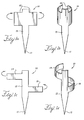
- the anchor 10 can include a longitudinal body 13 having a barb 11 at one end and first and second substantially opposing curved portions 15 disposed along at least a part of the length of, and substantially perpendicular to the longitudinal body 13.
- the anchor 10 has two substantially opposing portions 15 perpendicular to the longitudinal body 13. These portions 15 are shaped to fit about and to conform to a strut.
- an anchor is shown having more than two opposing portions, where there is a first curved portion 14 that is longitudinally offset from the second curved portion 18.
- the curved portions 15 of the example of Figure 1 a are configured for fastening the anchor 10 to the stent by snap fitting the portions 15 around a strut or, if necessary, soldering the portion 15 to the strut.
- the anchor also can include a longitudinal body 13 with more than one barb 11. The barb can be forked at the end to provide two or three separate prongs.
- the straight portions 15 shown in Figure 1a are bent in the direction shown by the arrows to provide the two curved portions 15 shown in Figure 1b .
- the anchor 1a would be pre-curved prior to fitting to a stent, such that the anchor 10 is provided in the form shown in Figure 1b .
- the longitudinal body is also radially curved, which provides rigidity and enhanced strength to the barb.
- the elongate body 13 may be radially straight, with the curvature being imparted solely to the arm portions 15.
- the anchor 10 may be curved onto the strut of a stent, that is applied to a stent a flat configuration as shown in Figure 1 a and then deformed around the stent strut into the shape shown in Figure 1b .
- These features of the anchor 10 can apply equally to the other examples disclosed herein and to all other examples falling within the scope of the original claims.
- Figure 1c shows a monolithic anchor 10 with two substantially opposing portions 14, 18 that are longitudinally offset to one another. As shown in Figure 1d , these portions 14, 18 are manipulated (deformed) in the direction shown by the arrows to provide two curved portions 14, 18 that in use conform to the tubular elongate portion of a stent strut.
- Figure 1e shows an anchor 10 also formed from a sheet of biocompatible material.
- Three arm portions 14, 16, 18 are bent in the direction shown by the arrows to provide the curved portions 14, 16, 18 shown in Figure 1f .
- Curved portions 14, 16, 18 are disposed along the length of and are substantially perpendicular to the longitudinal body 13.
- Curved portion 18 is longitudinally offset from and lies longitudinally between curved portions 14, 16 which extend from the other side of the elongate body portion 13.
- An anchor can be made having more than one, two, or even three curved portions where some of the curved portions are opposed to the remainder. The number of curved portions and their configuration can vary. Positioning the curved portions in opposing configurations facilitates the stable attachment of the anchor to the strut of the stent.
- the arms of the various examples of anchor disclosed herein and shown in the drawings extend perpendicularly from the elongate body portion 13 this may not be necessary.
- the arms may extend substantially perpendicularly thereto or at any other angle to the body portion. It is preferred that the arms, when wrapped in the curved configuration shown, do not overlap one another, either by way of their length (as shown for instance in Figures 1 a and 1 b) or by their shape or placement (as shown for instance in Figures 1c to 1f ).
- the anchor 10 also includes a barb 11 that, when the prosthesis is implanted into a vasculature, assists in securing the anchor and the stent graft to the vessel wall or to the wall of a mating graft.
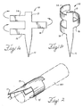
- the barb 11 can be parallel to the elongate portion of a stent strut 80, extend from the elongate portion at an angle away from the strut 80, as shown in Figure 2 , or bend towards the strut 80.
- the barb 11 in Figure 3b is in line with the stent elongate portion 80.
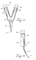
- the anchor 10 can have geometries permitting press-fit or snap-on placement of the anchor 10 onto a stent strut at either an elongate 80 portion or at the curvilinear 85, or apex, portion of a Z-stent, as shown in Figure 5a .
- a sheet of an appropriate material, such as an alloy, can be stamped to incorporate curved and linear segments that act to fasten the anchor 10 around the stent strut 80 and hold the anchor 10 in place.
- Figure 2 shows an anchor 10 fastened to the elongate portion 80 of a stent.
- Figure 5a shows an anchor 20 fastened to the curvilinear portion 85 of a stent.
- the two clamping portions 26, 28 of the anchor substantially mimic and conform to the curvilinear portion 85 of the stent.
- the clamping portions 26, 28 of the anchor 10 then can support the resultant forces and moments through the points of contact between the stent and the anchor 10 without the need for solder, welding, glue, or epoxy.
- FIGS. 3a and 3b are illustrations of steps that can be taken to fasten a monolithic anchor 10 having two offset curved portions 14, 18 to the elongate strut 80.
- the two curved portions 14, 18 are offset and opposed to one another and are bent to fit around the stent elongate portion 80.
- the longitudinal body 13 part of the anchor 10 is initially placed substantially perpendicular to the stent elongate portion 80 such that the elongate portion 80 lies between the curved portions 14, 18.
- the anchor 10 can then be rotated in a clockwise direction as shown by the arrows in Figure 3a to fasten the anchor 10 to the elongate portion 80.
- rotating the anchor 10 so that the longitudinal body 13 is in line with the elongate portion 80 of the stent strut can snap the curved portions 14, 18 around the stent strut, thus attaching the anchor 10 to the stent.
- the length of the arms 14 and 18, as well as the curvature of the elongate body portion 13, can provide a reliable fastening of the anchor to the stent strut 80.
- An anchor can be provided such that it is fastened to the elongate portion 80 by turning the anchor 10 in a counterclockwise or clockwise direction (depending upon the relative positions of the arms 14, 18).
- the curved portions 14, 18 also can be provided such that the longitudinal body 13 of the anchor 10 contacts the elongate portion and then turned 45 degrees or so to fit onto the elongate portion 80.
- arms 15 longitudinally aligned with one another (as in Figures 1a and 1b ) or sets of arms which encompass overlapping longitudinal extents of the elongate body (for example as with the example of Figures 1e and 1f ) these may be snap-fitted to the strut 80 by pressing the anchor 10 towards the strut 80.
- the curvature of the strut 80 will assist in splaying the arms outwardly until they pass the centre point (widest point) of the strut, beyond which they will snap back into position and fix the anchor around the strut 80.
- an endoluminal prosthesis can include a support structure comprising a curvilinear portion 85 having a first strut 82 and a second strut 88 meeting at an apex 83.
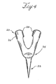
- the prosthesis also can include an anchor 20 comprising an anchor body and one or more barbs 21 extending outwardly from the anchor body.
- the anchor body fits at least partially about, and conforms to, the first strut 82, the second strut 88, and the apex 83.
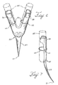
- the anchor has a longitudinal structure with a first end 22 with a barb 21 and a second, bifurcated end 25.
- the second end 25 includes a first substantially curved clamping portion 26 configured to fit about the first strut 82 and a second substantially curved clamping portion 28 configured to fit about the second strut 88.
- Figure 5a shows a stent curvilinear portion 85 in dashed lines along with the first 82 and second 88 struts meeting at an apex 83.
- the apex 83 points in one direction and when an anchor 20 is attached, the barb 21 can extend in that one direction.
- the barb 21 also can be bent at an angle or in a different direction than the apex 83.
- the second, bifurcated end 25 includes two substantially curved clamping portions 26, 28 that can be configured to fit about the two struts found on the curvilinear portion of a stent.
- the two substantially curved clamping portions 26, 28 can be designed for press-fit or snap-on placement onto the stent.
- the two substantially curved clamping portions 26, 28 also can be soldered onto the stent struts.
- Figures 5a and 5b show the anchor 20 fastened to the curvilinear portion 85 from the front ( Figure 5a ) and from a profile view ( Figure 5b ).
- the barb 21 can contact and embed into an endoluminal wall when implanted into a vessel.
- the anchor 20 in Figure 5b has a barb 21 that is bent at an angle such that the barb 21 would point away from where the stent graft (not shown) is positioned.
- the barb 21 also can be in line with the apex 83 as seen in Figure 5a or be bent laterally in a variety of directions.
- An anchor can be attached to the endoluminal support structure that has a curvilinear portion with a first strut and a second strut meeting at an apex.
- the method of attachment can include arranging a first end of the anchor so that it fits at least partially about, and conforms to, the first strut.
- a second end of the anchor is arranged so that it fits at least partially about, and conforms to, the second strut.
- the anchor can also be arranged so that it fits at least partially about, and conforms to, the apex.
- the anchor can be arranged such that it is snapped to the first strut, the second strut, and the apex of the curvilinear portion of a stent.
- support sutures 60 can be used to fasten the anchor 20 to a stent.
- Figure 6 shows an anchor 20 with a second bifurcated end 25 with one or more openings 62 in each substantially curved clamping portion 26, 28, through which support sutures 60 can be threaded.
- Figure 7 is a profile view of an anchor 20 having support sutures 60 threaded around the curvilinear portion 85, through the openings 62, and around the second curved portion 28.
- the support sutures 60 can be threaded at least partially around the first 26 and second 28 substantially curved clamping portion.
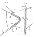
- FIGS 8a and 8b show anchors 102 and 92 attached to curvilinear 104 and elongate 94 stent struts.
- Anchors 102 and 92 are made of a plurality of independent wires arranged in a multi-filar tube having a first end, a second end and a longitudinal axis. In such a multi-filar anchor, at least one of the wires has an end that extends out of the multi-filar tube and forms a first barb that extends outwardly from the anchoring device.
- the wires are coiled around stent struts 104, 94 to form the multi-filar tubes.
- the anchors 102, 92 resemble a coil or barbed wire configuration.
- the wires can have a circular cross-section or a polygonal cross-section.
- the tube has a first end 101 disposed, at least in part, about the first strut 71 and a second end 103 disposed, at least in part, about the second strut 72.
- the tube is also disposed around the apex 79 of the curvilinear stent 104 strut.
- the multi-filar anchor 92 is disposed on an elongate stent strut 94 from the first end 73 to the second end 74 of the stent.
- the multi-filar anchors have wires wherein each of the wires have a first end disposed at or near the first end of the multi-filar tube and a second end disposed at or near the second end of the multi-filar tube.
- At least one wire in the multi-filar anchor has an end that forms at least one barb.
- the multi-filar anchors 102, 92 have barbs 108, 109, 98, 99 formed from the sharpened ends of corresponding wires.
- Barb 108 which extends outwardly from the anchor 102, is formed from a first wire having an end.
- the anchor 92 attached to the elongate strut 94 has a first end 91 that has a barb 99 disposed thereon and a second end 93 with a barb 98 disposed thereon. It is appreciated that a multi-filar anchor similar to that shown in Figure 8a can be attached to a Z-stent.
- a multi-filar anchor similar to that show in Figure 8b can be attached to other interconnected support structures or stents.
- anchor 94 can be threaded around an elongate stent strut 94.
- An anchor can be attached to the support structure in a position fixed longitudinally and rotationally. Although some incidental movement can be allowed, the anchor can be attached and fixed such that it will not move substantially longitudinally along a stent or rotate about the stent.
- the attachment is such that there can be little or no movement by the anchor independent of the stent structure. With monolithic anchors having bifurcated attachment ends, there can be little or no longitudinal or rotational movement.
- the anchor can be fastened to the stent by laser weld, adhesive, soldering, or friction fit.
- the anchor can also include Nitinol.
- the substantially curved clamping portions can include Nitinol. The Nitinol clamping portions can be configured to constrict around a stent strut and provide a secure attachment between the anchor and the stent.
- the anchors could be provided in a substantially flat form and then made to wrap around a stent strut by heating through the transition temperature.
- the anchors could be configured to the curved shape shown, for example, in Figures 1b, 1d and 1f while in their martensitic phase, fitted to a stent strut and then heated through their transition temperature (when implanted with the medical device into a patient for instance), upon which the return to the memory shape will press the anchor onto the stent strut to tighten the fit.
Landscapes
- Health & Medical Sciences (AREA)
- Engineering & Computer Science (AREA)
- Biomedical Technology (AREA)
- Cardiology (AREA)
- Oral & Maxillofacial Surgery (AREA)
- Transplantation (AREA)
- Heart & Thoracic Surgery (AREA)
- Vascular Medicine (AREA)
- Life Sciences & Earth Sciences (AREA)
- Animal Behavior & Ethology (AREA)
- General Health & Medical Sciences (AREA)
- Public Health (AREA)
- Veterinary Medicine (AREA)
- Gastroenterology & Hepatology (AREA)
- Pulmonology (AREA)
- Prostheses (AREA)
- Media Introduction/Drainage Providing Device (AREA)
Applications Claiming Priority (3)
| Application Number | Priority Date | Filing Date | Title |
|---|---|---|---|
| US9317208P | 2008-08-29 | 2008-08-29 | |
| US12/360,638 US8394139B2 (en) | 2008-08-29 | 2009-01-27 | Barbed anchors for wire stent |
| PCT/US2009/004830 WO2010024881A1 (en) | 2008-08-29 | 2009-08-25 | Barbed anchors for implantable medical device |
Publications (2)
| Publication Number | Publication Date |
|---|---|
| EP2331027A1 EP2331027A1 (en) | 2011-06-15 |
| EP2331027B1 true EP2331027B1 (en) | 2016-03-23 |
Family
ID=41350636
Family Applications (1)
| Application Number | Title | Priority Date | Filing Date |
|---|---|---|---|
| EP09789204.6A Not-in-force EP2331027B1 (en) | 2008-08-29 | 2009-08-25 | Barbed anchors for implantable medical device |
Country Status (5)
| Country | Link |
|---|---|
| US (2) | US8394139B2 (enExample) |
| EP (1) | EP2331027B1 (enExample) |
| JP (1) | JP5562960B2 (enExample) |
| AU (1) | AU2009286065B2 (enExample) |
| WO (1) | WO2010024881A1 (enExample) |
Families Citing this family (46)
| Publication number | Priority date | Publication date | Assignee | Title |
|---|---|---|---|---|
| US7147661B2 (en) | 2001-12-20 | 2006-12-12 | Boston Scientific Santa Rosa Corp. | Radially expandable stent |
| US7896911B2 (en) | 2007-12-12 | 2011-03-01 | Innovasc Llc | Device and method for tacking plaque to blood vessel wall |
| US8128677B2 (en) | 2007-12-12 | 2012-03-06 | Intact Vascular LLC | Device and method for tacking plaque to a blood vessel wall |
| US9603730B2 (en) | 2007-12-12 | 2017-03-28 | Intact Vascular, Inc. | Endoluminal device and method |
| US10166127B2 (en) | 2007-12-12 | 2019-01-01 | Intact Vascular, Inc. | Endoluminal device and method |
| US10022250B2 (en) | 2007-12-12 | 2018-07-17 | Intact Vascular, Inc. | Deployment device for placement of multiple intraluminal surgical staples |
| US9375327B2 (en) | 2007-12-12 | 2016-06-28 | Intact Vascular, Inc. | Endovascular implant |
| US7905915B2 (en) * | 2007-12-27 | 2011-03-15 | Cook Incorporated | Z-stent with incorporated barbs |
| US11207199B2 (en) | 2008-06-11 | 2021-12-28 | Q3 Medical Devices Limited | Stent with anti-migration devices |
| US8696739B2 (en) | 2008-08-29 | 2014-04-15 | Cook Medical Technologies Llc | Barbed anchor |
| GB2472602B (en) * | 2009-08-11 | 2011-12-14 | Cook Medical Technologies Llc | Medical device and method of manufacturing same |
| GB2472603B (en) * | 2009-08-11 | 2011-12-14 | Cook Medical Technologies Llc | Implantable medical device |
| JP2012040145A (ja) * | 2010-08-18 | 2012-03-01 | Terumo Corp | 医療用チューブ保護カバー |
| EP2525742B1 (en) * | 2010-10-29 | 2015-03-18 | Cook Medical Technologies LLC | Medical device delivery system and deployment method |
| US9744033B2 (en) | 2011-04-01 | 2017-08-29 | W.L. Gore & Associates, Inc. | Elastomeric leaflet for prosthetic heart valves |
| US10271973B2 (en) | 2011-06-03 | 2019-04-30 | Intact Vascular, Inc. | Endovascular implant |
| US10117765B2 (en) | 2011-06-14 | 2018-11-06 | W.L. Gore Associates, Inc | Apposition fiber for use in endoluminal deployment of expandable implants |
| US8870947B2 (en) * | 2011-09-16 | 2014-10-28 | W.L. Gore & Associates, Inc. | Medical device fixation anchors |
| US9554806B2 (en) | 2011-09-16 | 2017-01-31 | W. L. Gore & Associates, Inc. | Occlusive devices |
| US9877858B2 (en) | 2011-11-14 | 2018-01-30 | W. L. Gore & Associates, Inc. | External steerable fiber for use in endoluminal deployment of expandable devices |
| US9782282B2 (en) | 2011-11-14 | 2017-10-10 | W. L. Gore & Associates, Inc. | External steerable fiber for use in endoluminal deployment of expandable devices |
| WO2013112768A1 (en) | 2012-01-25 | 2013-08-01 | Intact Vascular, Inc. | Endoluminal device and method |
| US9375308B2 (en) | 2012-03-13 | 2016-06-28 | W. L. Gore & Associates, Inc. | External steerable fiber for use in endoluminal deployment of expandable devices |
| US9681965B2 (en) | 2012-07-31 | 2017-06-20 | Cook Medical Technologies Llc | Barbed anchors for attachment to endoluminal prosthesis |
| US10959715B2 (en) | 2012-10-31 | 2021-03-30 | W. L. Gore & Associates, Inc. | Devices and methods related to deposited support structures |
| US11744594B2 (en) * | 2012-11-16 | 2023-09-05 | W.L. Gore & Associates, Inc. | Space filling devices |
| US10675012B2 (en) | 2012-11-16 | 2020-06-09 | W. L. Gore & Associates, Inc. | Joint assembly for medical devices |
| US11911258B2 (en) | 2013-06-26 | 2024-02-27 | W. L. Gore & Associates, Inc. | Space filling devices |
| US9375336B1 (en) | 2015-01-29 | 2016-06-28 | Intact Vascular, Inc. | Delivery device and method of delivery |
| US9433520B2 (en) | 2015-01-29 | 2016-09-06 | Intact Vascular, Inc. | Delivery device and method of delivery |
| EP3258891A1 (en) | 2015-02-20 | 2017-12-27 | Boston Scientific Scimed, Inc. | Stent with retractable anchors |
| CN114652385A (zh) | 2015-05-14 | 2022-06-24 | W.L.戈尔及同仁股份有限公司 | 用于闭塞心耳的装置 |
| CA2938576A1 (en) | 2015-08-12 | 2017-02-12 | Howmedica Osteonics Corp. | Methods for forming scaffolds |
| US11331191B2 (en) | 2015-08-12 | 2022-05-17 | Howmedica Osteonics Corp. | Bioactive soft tissue implant and methods of manufacture and use thereof |
| US10993824B2 (en) | 2016-01-01 | 2021-05-04 | Intact Vascular, Inc. | Delivery device and method of delivery |
| EP4356938A3 (en) | 2016-05-02 | 2024-07-24 | Howmedica Osteonics Corp. | Bioactive soft tissue implant and methods of manufacture and use thereof |
| WO2018089560A1 (en) | 2016-11-09 | 2018-05-17 | Boston Scientific Scimed, Inc. | Stent anchoring system |
| AU2018230960B2 (en) | 2017-03-08 | 2020-07-09 | W. L. Gore & Associates, Inc. | Steering wire attach for angulation |
| US11660218B2 (en) | 2017-07-26 | 2023-05-30 | Intact Vascular, Inc. | Delivery device and method of delivery |
| US11173023B2 (en) | 2017-10-16 | 2021-11-16 | W. L. Gore & Associates, Inc. | Medical devices and anchors therefor |
| JP7555110B2 (ja) * | 2018-05-30 | 2024-09-24 | ファウンドリー イノベーション アンド リサーチ 1,リミテッド | 無線共振回路および可変インダクタンス血管監視インプラント、並びに、そのアンカー構造 |
| US11497632B2 (en) | 2018-07-30 | 2022-11-15 | Cook Medical Technologies Llc | Spring barb for medical device |
| AU2018438636B2 (en) | 2018-08-31 | 2022-06-30 | W. L. Gore & Associates, Inc. | Apparatus, system, and method for steering an implantable medical device |
| EP3843659A1 (en) | 2018-08-31 | 2021-07-07 | W.L. Gore & Associates, Inc. | Apparatus, system, and method for steering an implantable medical device |
| CN113924067A (zh) * | 2019-03-19 | 2022-01-11 | Q3医疗设备有限公司 | 带有防移动装置的支架 |
| EP4444191A4 (en) * | 2021-12-07 | 2026-02-11 | Endomatic Ltd | ANCHORING ELEMENTS FOR A SLAGGING IMPLANT |
Citations (1)
| Publication number | Priority date | Publication date | Assignee | Title |
|---|---|---|---|---|
| WO2001058364A1 (en) * | 2000-02-09 | 2001-08-16 | Eva Corporation | Surgical fastener |
Family Cites Families (43)
| Publication number | Priority date | Publication date | Assignee | Title |
|---|---|---|---|---|
| US5693083A (en) * | 1983-12-09 | 1997-12-02 | Endovascular Technologies, Inc. | Thoracic graft and delivery catheter |
| US5104399A (en) * | 1986-12-10 | 1992-04-14 | Endovascular Technologies, Inc. | Artificial graft and implantation method |
| JPH0228247U (enExample) * | 1988-08-11 | 1990-02-23 | ||
| FR2689388B1 (fr) * | 1992-04-07 | 1999-07-16 | Celsa Lg | Filtre sanguin perfectionne eventuellement resorbable. |
| US5843167A (en) * | 1993-04-22 | 1998-12-01 | C. R. Bard, Inc. | Method and apparatus for recapture of hooked endoprosthesis |
| AU689094B2 (en) * | 1993-04-22 | 1998-03-26 | C.R. Bard Inc. | Non-migrating vascular prosthesis and minimally invasive placement system therefor |
| US5397355A (en) * | 1994-07-19 | 1995-03-14 | Stentco, Inc. | Intraluminal stent |
| AU708360B2 (en) * | 1994-09-15 | 1999-08-05 | C.R. Bard Inc. | Hooked endoprosthesis |
| AU3783195A (en) * | 1994-11-15 | 1996-05-23 | Advanced Cardiovascular Systems Inc. | Intraluminal stent for attaching a graft |
| US6214025B1 (en) * | 1994-11-30 | 2001-04-10 | Boston Scientific Corporation | Self-centering, self-expanding and retrievable vena cava filter |
| FR2737404B1 (fr) * | 1995-08-03 | 1997-09-19 | Braun Celsa Sa | Prothese implantable dans un conduit humain ou animal, telle qu'un elargisseur de paroi, ou une prothese pour anevrisme |
| US5824042A (en) * | 1996-04-05 | 1998-10-20 | Medtronic, Inc. | Endoluminal prostheses having position indicating markers |
| US6113612A (en) * | 1998-11-06 | 2000-09-05 | St. Jude Medical Cardiovascular Group, Inc. | Medical anastomosis apparatus |
| US6231581B1 (en) * | 1998-12-16 | 2001-05-15 | Boston Scientific Corporation | Implantable device anchors |
| US6918921B2 (en) * | 1999-05-07 | 2005-07-19 | Salviac Limited | Support frame for an embolic protection device |
| US6409757B1 (en) * | 1999-09-15 | 2002-06-25 | Eva Corporation | Method and apparatus for supporting a graft assembly |
| US6231561B1 (en) * | 1999-09-20 | 2001-05-15 | Appriva Medical, Inc. | Method and apparatus for closing a body lumen |
| US7004970B2 (en) * | 1999-10-20 | 2006-02-28 | Anulex Technologies, Inc. | Methods and devices for spinal disc annulus reconstruction and repair |
| US6821291B2 (en) * | 2001-06-01 | 2004-11-23 | Ams Research Corporation | Retrievable stent and method of use thereof |
| US7128754B2 (en) * | 2001-11-28 | 2006-10-31 | Aptus Endosystems, Inc. | Catheter-based fastener implantation apparatus and methods |
| US7331992B2 (en) * | 2002-02-20 | 2008-02-19 | Bard Peripheral Vascular, Inc. | Anchoring device for an endoluminal prosthesis |
| US20040117004A1 (en) * | 2002-05-16 | 2004-06-17 | Osborne Thomas A. | Stent and method of forming a stent with integral barbs |
| US7828839B2 (en) * | 2002-05-16 | 2010-11-09 | Cook Incorporated | Flexible barb for anchoring a prosthesis |
| AU2003243204B2 (en) * | 2002-05-16 | 2008-09-18 | Cook Medical Technologies Llc | Flexible barb for anchoring a prosthesis |
| US6984244B2 (en) * | 2003-03-27 | 2006-01-10 | Endovascular Technologies, Inc. | Delivery system for endoluminal implant |
| US20050070993A1 (en) * | 2003-09-29 | 2005-03-31 | Peter Boekstegers | Methods of retroperfusion and related devices |
| EP1708655A1 (en) * | 2003-12-09 | 2006-10-11 | GI Dynamics, Inc. | Apparatus to be anchored within the gastrointestinal tract and anchoring method |
| WO2005070337A2 (en) * | 2004-01-20 | 2005-08-04 | Cook Incorporated | Endoluminal stent graft with sutured attachment |
| AU2005209274B2 (en) * | 2004-01-27 | 2010-08-12 | Cook Medical Technologies Llc | Anchoring barb for attachment to a medical prosthesis |
| JP4901087B2 (ja) * | 2004-09-24 | 2012-03-21 | オリンパス株式会社 | ステント導入部材、ステントデリバリーカテーテル、及び内視鏡処置システム |
| US8298281B2 (en) * | 2006-07-18 | 2012-10-30 | Cordis Corporation | Twisted anchoring barb for stent of abdominal aortic aneurysm (AAA) device |
| JP5468899B2 (ja) * | 2006-07-20 | 2014-04-09 | アフィニウム ファーマシューティカルズ, インク. | Fabiインヒビターとしてのアクリルアミド誘導体 |
| ATE458508T1 (de) * | 2006-08-28 | 2010-03-15 | Wilson Cook Medical Inc | Stent mit antimikrobieller drainagelumen- oberfläche |
| US9237959B2 (en) * | 2007-08-17 | 2016-01-19 | Cook Medical Technologies Llc | Stent and barb |
| US20090149946A1 (en) * | 2007-12-05 | 2009-06-11 | Cook Incorporated | Stent having at least one barb and methods of manufacture |
| US20090149945A1 (en) * | 2007-12-06 | 2009-06-11 | Abbott Carciovascular Systems Inc., A California Corporation | Prosthetic support for flaccid arterial segments |
| US7905915B2 (en) * | 2007-12-27 | 2011-03-15 | Cook Incorporated | Z-stent with incorporated barbs |
| US8163007B2 (en) * | 2008-02-08 | 2012-04-24 | Cook Medical Technologies Llc | Stent designs for use with one or more trigger wires |
| US8696739B2 (en) * | 2008-08-29 | 2014-04-15 | Cook Medical Technologies Llc | Barbed anchor |
| US8834553B2 (en) * | 2009-09-11 | 2014-09-16 | Gi Dynamics, Inc. | Anchors with biodegradable constraints |
| GB201109315D0 (en) * | 2011-06-03 | 2011-07-20 | Vascutek Ltd | Prosthesis |
| US8870947B2 (en) * | 2011-09-16 | 2014-10-28 | W.L. Gore & Associates, Inc. | Medical device fixation anchors |
| US9681965B2 (en) * | 2012-07-31 | 2017-06-20 | Cook Medical Technologies Llc | Barbed anchors for attachment to endoluminal prosthesis |
-
2009
- 2009-01-27 US US12/360,638 patent/US8394139B2/en not_active Expired - Fee Related
- 2009-08-25 AU AU2009286065A patent/AU2009286065B2/en not_active Ceased
- 2009-08-25 WO PCT/US2009/004830 patent/WO2010024881A1/en not_active Ceased
- 2009-08-25 EP EP09789204.6A patent/EP2331027B1/en not_active Not-in-force
- 2009-08-25 JP JP2011524988A patent/JP5562960B2/ja not_active Expired - Fee Related
-
2013
- 2013-03-08 US US13/790,855 patent/US8858617B2/en active Active
Patent Citations (1)
| Publication number | Priority date | Publication date | Assignee | Title |
|---|---|---|---|---|
| WO2001058364A1 (en) * | 2000-02-09 | 2001-08-16 | Eva Corporation | Surgical fastener |
Also Published As
| Publication number | Publication date |
|---|---|
| US8394139B2 (en) | 2013-03-12 |
| AU2009286065B2 (en) | 2013-12-05 |
| JP5562960B2 (ja) | 2014-07-30 |
| US20130190858A1 (en) | 2013-07-25 |
| AU2009286065A1 (en) | 2010-03-04 |
| EP2331027A1 (en) | 2011-06-15 |
| US8858617B2 (en) | 2014-10-14 |
| US20100057195A1 (en) | 2010-03-04 |
| JP2012501209A (ja) | 2012-01-19 |
| WO2010024881A1 (en) | 2010-03-04 |
Similar Documents
| Publication | Publication Date | Title |
|---|---|---|
| EP2331027B1 (en) | Barbed anchors for implantable medical device | |
| US8696739B2 (en) | Barbed anchor | |
| US8632581B2 (en) | Conformable end sealing stent | |
| US20050267560A1 (en) | Implantable bioabsorbable valve support frame | |
| EP2164426B1 (en) | Stent attachment for endovascular aneurysm repair | |
| US9517123B2 (en) | Endovascular prosthesis and a method of connecting a structural component and a woven graft material | |
| US8157855B2 (en) | Detachable segment stent | |
| US9237959B2 (en) | Stent and barb | |
| US20090149946A1 (en) | Stent having at least one barb and methods of manufacture | |
| US20040215329A1 (en) | Stent with cover connectors | |
| US10149775B2 (en) | Barbed anchors for attachment to endoluminal prosthesis | |
| EP1965731B1 (en) | Endoprosthesis and method of connecting a structural component and a woven graft material | |
| EP4093326B1 (en) | Endoprosthesis and method of manufacturing an endoprosthesis |
Legal Events
| Date | Code | Title | Description |
|---|---|---|---|
| PUAI | Public reference made under article 153(3) epc to a published international application that has entered the european phase |
Free format text: ORIGINAL CODE: 0009012 |
|
| 17P | Request for examination filed |
Effective date: 20110323 |
|
| AK | Designated contracting states |
Kind code of ref document: A1 Designated state(s): AT BE BG CH CY CZ DE DK EE ES FI FR GB GR HR HU IE IS IT LI LT LU LV MC MK MT NL NO PL PT RO SE SI SK SM TR |
|
| AX | Request for extension of the european patent |
Extension state: AL BA RS |
|
| RIN1 | Information on inventor provided before grant (corrected) |
Inventor name: DIERKING, WILLIAM, K. Inventor name: HARDERT, MICHAEL, W. Inventor name: OSBORNE, THOMAS, A. Inventor name: RASMUSSEN, ERIK, E. Inventor name: ROEDER, BLAYNE, A. Inventor name: URBANSKI, JULIE, E. Inventor name: OEHLENSCHLAEGER, BENT Inventor name: ORR, DAVID, E. |
|
| DAX | Request for extension of the european patent (deleted) | ||
| RAP1 | Party data changed (applicant data changed or rights of an application transferred) |
Owner name: MED INSTITUTE, INC. Owner name: COOK MEDICAL TECHNOLOGIES LLC Owner name: WILLIAM COOK EUROPE APS |
|
| RAP1 | Party data changed (applicant data changed or rights of an application transferred) |
Owner name: COOK MEDICAL TECHNOLOGIES LLC |
|
| 17Q | First examination report despatched |
Effective date: 20150521 |
|
| GRAP | Despatch of communication of intention to grant a patent |
Free format text: ORIGINAL CODE: EPIDOSNIGR1 |
|
| INTG | Intention to grant announced |
Effective date: 20151117 |
|
| GRAS | Grant fee paid |
Free format text: ORIGINAL CODE: EPIDOSNIGR3 |
|
| GRAA | (expected) grant |
Free format text: ORIGINAL CODE: 0009210 |
|
| AK | Designated contracting states |
Kind code of ref document: B1 Designated state(s): AT BE BG CH CY CZ DE DK EE ES FI FR GB GR HR HU IE IS IT LI LT LU LV MC MK MT NL NO PL PT RO SE SI SK SM TR |
|
| REG | Reference to a national code |
Ref country code: GB Ref legal event code: FG4D |
|
| REG | Reference to a national code |
Ref country code: CH Ref legal event code: EP |
|
| REG | Reference to a national code |
Ref country code: AT Ref legal event code: REF Ref document number: 782367 Country of ref document: AT Kind code of ref document: T Effective date: 20160415 |
|
| REG | Reference to a national code |
Ref country code: IE Ref legal event code: FG4D |
|
| REG | Reference to a national code |
Ref country code: DE Ref legal event code: R096 Ref document number: 602009037118 Country of ref document: DE |
|
| REG | Reference to a national code |
Ref country code: LT Ref legal event code: MG4D |
|
| REG | Reference to a national code |
Ref country code: NL Ref legal event code: MP Effective date: 20160323 |
|
| PG25 | Lapsed in a contracting state [announced via postgrant information from national office to epo] |
Ref country code: NO Free format text: LAPSE BECAUSE OF FAILURE TO SUBMIT A TRANSLATION OF THE DESCRIPTION OR TO PAY THE FEE WITHIN THE PRESCRIBED TIME-LIMIT Effective date: 20160623 Ref country code: FI Free format text: LAPSE BECAUSE OF FAILURE TO SUBMIT A TRANSLATION OF THE DESCRIPTION OR TO PAY THE FEE WITHIN THE PRESCRIBED TIME-LIMIT Effective date: 20160323 |
|
| REG | Reference to a national code |
Ref country code: AT Ref legal event code: MK05 Ref document number: 782367 Country of ref document: AT Kind code of ref document: T Effective date: 20160323 |
|
| PG25 | Lapsed in a contracting state [announced via postgrant information from national office to epo] |
Ref country code: LV Free format text: LAPSE BECAUSE OF FAILURE TO SUBMIT A TRANSLATION OF THE DESCRIPTION OR TO PAY THE FEE WITHIN THE PRESCRIBED TIME-LIMIT Effective date: 20160323 Ref country code: NL Free format text: LAPSE BECAUSE OF FAILURE TO SUBMIT A TRANSLATION OF THE DESCRIPTION OR TO PAY THE FEE WITHIN THE PRESCRIBED TIME-LIMIT Effective date: 20160323 Ref country code: LT Free format text: LAPSE BECAUSE OF FAILURE TO SUBMIT A TRANSLATION OF THE DESCRIPTION OR TO PAY THE FEE WITHIN THE PRESCRIBED TIME-LIMIT Effective date: 20160323 Ref country code: SE Free format text: LAPSE BECAUSE OF FAILURE TO SUBMIT A TRANSLATION OF THE DESCRIPTION OR TO PAY THE FEE WITHIN THE PRESCRIBED TIME-LIMIT Effective date: 20160323 |
|
| PG25 | Lapsed in a contracting state [announced via postgrant information from national office to epo] |
Ref country code: EE Free format text: LAPSE BECAUSE OF FAILURE TO SUBMIT A TRANSLATION OF THE DESCRIPTION OR TO PAY THE FEE WITHIN THE PRESCRIBED TIME-LIMIT Effective date: 20160323 Ref country code: PL Free format text: LAPSE BECAUSE OF FAILURE TO SUBMIT A TRANSLATION OF THE DESCRIPTION OR TO PAY THE FEE WITHIN THE PRESCRIBED TIME-LIMIT Effective date: 20160323 Ref country code: IS Free format text: LAPSE BECAUSE OF FAILURE TO SUBMIT A TRANSLATION OF THE DESCRIPTION OR TO PAY THE FEE WITHIN THE PRESCRIBED TIME-LIMIT Effective date: 20160723 |
|
| PG25 | Lapsed in a contracting state [announced via postgrant information from national office to epo] |
Ref country code: CZ Free format text: LAPSE BECAUSE OF FAILURE TO SUBMIT A TRANSLATION OF THE DESCRIPTION OR TO PAY THE FEE WITHIN THE PRESCRIBED TIME-LIMIT Effective date: 20160323 Ref country code: AT Free format text: LAPSE BECAUSE OF FAILURE TO SUBMIT A TRANSLATION OF THE DESCRIPTION OR TO PAY THE FEE WITHIN THE PRESCRIBED TIME-LIMIT Effective date: 20160323 Ref country code: SM Free format text: LAPSE BECAUSE OF FAILURE TO SUBMIT A TRANSLATION OF THE DESCRIPTION OR TO PAY THE FEE WITHIN THE PRESCRIBED TIME-LIMIT Effective date: 20160323 Ref country code: SK Free format text: LAPSE BECAUSE OF FAILURE TO SUBMIT A TRANSLATION OF THE DESCRIPTION OR TO PAY THE FEE WITHIN THE PRESCRIBED TIME-LIMIT Effective date: 20160323 Ref country code: PT Free format text: LAPSE BECAUSE OF FAILURE TO SUBMIT A TRANSLATION OF THE DESCRIPTION OR TO PAY THE FEE WITHIN THE PRESCRIBED TIME-LIMIT Effective date: 20160725 Ref country code: ES Free format text: LAPSE BECAUSE OF FAILURE TO SUBMIT A TRANSLATION OF THE DESCRIPTION OR TO PAY THE FEE WITHIN THE PRESCRIBED TIME-LIMIT Effective date: 20160323 Ref country code: RO Free format text: LAPSE BECAUSE OF FAILURE TO SUBMIT A TRANSLATION OF THE DESCRIPTION OR TO PAY THE FEE WITHIN THE PRESCRIBED TIME-LIMIT Effective date: 20160323 |
|
| PG25 | Lapsed in a contracting state [announced via postgrant information from national office to epo] |
Ref country code: BE Free format text: LAPSE BECAUSE OF FAILURE TO SUBMIT A TRANSLATION OF THE DESCRIPTION OR TO PAY THE FEE WITHIN THE PRESCRIBED TIME-LIMIT Effective date: 20160323 Ref country code: IT Free format text: LAPSE BECAUSE OF FAILURE TO SUBMIT A TRANSLATION OF THE DESCRIPTION OR TO PAY THE FEE WITHIN THE PRESCRIBED TIME-LIMIT Effective date: 20160323 |
|
| REG | Reference to a national code |
Ref country code: DE Ref legal event code: R097 Ref document number: 602009037118 Country of ref document: DE |
|
| PLBE | No opposition filed within time limit |
Free format text: ORIGINAL CODE: 0009261 |
|
| STAA | Information on the status of an ep patent application or granted ep patent |
Free format text: STATUS: NO OPPOSITION FILED WITHIN TIME LIMIT |
|
| PG25 | Lapsed in a contracting state [announced via postgrant information from national office to epo] |
Ref country code: DK Free format text: LAPSE BECAUSE OF FAILURE TO SUBMIT A TRANSLATION OF THE DESCRIPTION OR TO PAY THE FEE WITHIN THE PRESCRIBED TIME-LIMIT Effective date: 20160323 |
|
| PG25 | Lapsed in a contracting state [announced via postgrant information from national office to epo] |
Ref country code: BG Free format text: LAPSE BECAUSE OF FAILURE TO SUBMIT A TRANSLATION OF THE DESCRIPTION OR TO PAY THE FEE WITHIN THE PRESCRIBED TIME-LIMIT Effective date: 20160623 |
|
| 26N | No opposition filed |
Effective date: 20170102 |
|
| PG25 | Lapsed in a contracting state [announced via postgrant information from national office to epo] |
Ref country code: MC Free format text: LAPSE BECAUSE OF FAILURE TO SUBMIT A TRANSLATION OF THE DESCRIPTION OR TO PAY THE FEE WITHIN THE PRESCRIBED TIME-LIMIT Effective date: 20160323 |
|
| REG | Reference to a national code |
Ref country code: CH Ref legal event code: PL |
|
| PG25 | Lapsed in a contracting state [announced via postgrant information from national office to epo] |
Ref country code: CH Free format text: LAPSE BECAUSE OF NON-PAYMENT OF DUE FEES Effective date: 20160831 Ref country code: LI Free format text: LAPSE BECAUSE OF NON-PAYMENT OF DUE FEES Effective date: 20160831 |
|
| REG | Reference to a national code |
Ref country code: FR Ref legal event code: ST Effective date: 20170428 |
|
| PG25 | Lapsed in a contracting state [announced via postgrant information from national office to epo] |
Ref country code: SI Free format text: LAPSE BECAUSE OF FAILURE TO SUBMIT A TRANSLATION OF THE DESCRIPTION OR TO PAY THE FEE WITHIN THE PRESCRIBED TIME-LIMIT Effective date: 20160323 |
|
| PG25 | Lapsed in a contracting state [announced via postgrant information from national office to epo] |
Ref country code: FR Free format text: LAPSE BECAUSE OF NON-PAYMENT OF DUE FEES Effective date: 20160831 |
|
| PG25 | Lapsed in a contracting state [announced via postgrant information from national office to epo] |
Ref country code: LU Free format text: LAPSE BECAUSE OF NON-PAYMENT OF DUE FEES Effective date: 20160825 |
|
| PG25 | Lapsed in a contracting state [announced via postgrant information from national office to epo] |
Ref country code: CY Free format text: LAPSE BECAUSE OF FAILURE TO SUBMIT A TRANSLATION OF THE DESCRIPTION OR TO PAY THE FEE WITHIN THE PRESCRIBED TIME-LIMIT Effective date: 20160323 Ref country code: HU Free format text: LAPSE BECAUSE OF FAILURE TO SUBMIT A TRANSLATION OF THE DESCRIPTION OR TO PAY THE FEE WITHIN THE PRESCRIBED TIME-LIMIT; INVALID AB INITIO Effective date: 20090825 |
|
| PG25 | Lapsed in a contracting state [announced via postgrant information from national office to epo] |
Ref country code: HR Free format text: LAPSE BECAUSE OF FAILURE TO SUBMIT A TRANSLATION OF THE DESCRIPTION OR TO PAY THE FEE WITHIN THE PRESCRIBED TIME-LIMIT Effective date: 20160323 Ref country code: MK Free format text: LAPSE BECAUSE OF FAILURE TO SUBMIT A TRANSLATION OF THE DESCRIPTION OR TO PAY THE FEE WITHIN THE PRESCRIBED TIME-LIMIT Effective date: 20160323 Ref country code: MT Free format text: LAPSE BECAUSE OF NON-PAYMENT OF DUE FEES Effective date: 20160831 Ref country code: GR Free format text: LAPSE BECAUSE OF FAILURE TO SUBMIT A TRANSLATION OF THE DESCRIPTION OR TO PAY THE FEE WITHIN THE PRESCRIBED TIME-LIMIT Effective date: 20160323 Ref country code: TR Free format text: LAPSE BECAUSE OF FAILURE TO SUBMIT A TRANSLATION OF THE DESCRIPTION OR TO PAY THE FEE WITHIN THE PRESCRIBED TIME-LIMIT Effective date: 20160323 |
|
| P01 | Opt-out of the competence of the unified patent court (upc) registered |
Effective date: 20230602 |
|
| PGFP | Annual fee paid to national office [announced via postgrant information from national office to epo] |
Ref country code: IE Payment date: 20230726 Year of fee payment: 15 Ref country code: GB Payment date: 20230712 Year of fee payment: 15 |
|
| PGFP | Annual fee paid to national office [announced via postgrant information from national office to epo] |
Ref country code: DE Payment date: 20230711 Year of fee payment: 15 |
|
| REG | Reference to a national code |
Ref country code: DE Ref legal event code: R119 Ref document number: 602009037118 Country of ref document: DE |
|
| GBPC | Gb: european patent ceased through non-payment of renewal fee |
Effective date: 20240825 |
|
| PG25 | Lapsed in a contracting state [announced via postgrant information from national office to epo] |
Ref country code: DE Free format text: LAPSE BECAUSE OF NON-PAYMENT OF DUE FEES Effective date: 20250301 |
|
| PG25 | Lapsed in a contracting state [announced via postgrant information from national office to epo] |
Ref country code: GB Free format text: LAPSE BECAUSE OF NON-PAYMENT OF DUE FEES Effective date: 20240825 |
|
| PG25 | Lapsed in a contracting state [announced via postgrant information from national office to epo] |
Ref country code: IE Free format text: LAPSE BECAUSE OF NON-PAYMENT OF DUE FEES Effective date: 20240825 |