EP2330711A1 - Method for controlling interconnection system - Google Patents
Method for controlling interconnection system Download PDFInfo
- Publication number
- EP2330711A1 EP2330711A1 EP09817699A EP09817699A EP2330711A1 EP 2330711 A1 EP2330711 A1 EP 2330711A1 EP 09817699 A EP09817699 A EP 09817699A EP 09817699 A EP09817699 A EP 09817699A EP 2330711 A1 EP2330711 A1 EP 2330711A1
- Authority
- EP
- European Patent Office
- Prior art keywords
- power
- interconnected system
- sodium
- generator
- sulfur battery
- Prior art date
- Legal status (The legal status is an assumption and is not a legal conclusion. Google has not performed a legal analysis and makes no representation as to the accuracy of the status listed.)
- Granted
Links
- 238000000034 method Methods 0.000 title claims description 21
- BNOODXBBXFZASF-UHFFFAOYSA-N [Na].[S] Chemical compound [Na].[S] BNOODXBBXFZASF-UHFFFAOYSA-N 0.000 claims abstract description 55
- 238000010248 power generation Methods 0.000 claims abstract description 55
- 230000005540 biological transmission Effects 0.000 claims abstract description 14
- 230000007423 decrease Effects 0.000 description 8
- 238000007599 discharging Methods 0.000 description 7
- 230000002457 bidirectional effect Effects 0.000 description 5
- CURLTUGMZLYLDI-UHFFFAOYSA-N Carbon dioxide Chemical compound O=C=O CURLTUGMZLYLDI-UHFFFAOYSA-N 0.000 description 4
- 238000010586 diagram Methods 0.000 description 4
- 230000000052 comparative effect Effects 0.000 description 3
- 229910002092 carbon dioxide Inorganic materials 0.000 description 2
- 239000001569 carbon dioxide Substances 0.000 description 2
- 238000006243 chemical reaction Methods 0.000 description 1
- 238000012986 modification Methods 0.000 description 1
- 230000004048 modification Effects 0.000 description 1
- 239000003208 petroleum Substances 0.000 description 1
- 230000002265 prevention Effects 0.000 description 1
- 229910052717 sulfur Inorganic materials 0.000 description 1
- 239000011593 sulfur Substances 0.000 description 1
- 238000010792 warming Methods 0.000 description 1
Images


Classifications
-
- H—ELECTRICITY
- H02—GENERATION; CONVERSION OR DISTRIBUTION OF ELECTRIC POWER
- H02J—CIRCUIT ARRANGEMENTS OR SYSTEMS FOR SUPPLYING OR DISTRIBUTING ELECTRIC POWER; SYSTEMS FOR STORING ELECTRIC ENERGY
- H02J3/00—Circuit arrangements for ac mains or ac distribution networks
- H02J3/28—Arrangements for balancing of the load in a network by storage of energy
- H02J3/32—Arrangements for balancing of the load in a network by storage of energy using batteries with converting means
-
- H—ELECTRICITY
- H02—GENERATION; CONVERSION OR DISTRIBUTION OF ELECTRIC POWER
- H02J—CIRCUIT ARRANGEMENTS OR SYSTEMS FOR SUPPLYING OR DISTRIBUTING ELECTRIC POWER; SYSTEMS FOR STORING ELECTRIC ENERGY
- H02J3/00—Circuit arrangements for ac mains or ac distribution networks
- H02J3/38—Arrangements for parallely feeding a single network by two or more generators, converters or transformers
- H02J3/381—Dispersed generators
-
- H—ELECTRICITY
- H02—GENERATION; CONVERSION OR DISTRIBUTION OF ELECTRIC POWER
- H02J—CIRCUIT ARRANGEMENTS OR SYSTEMS FOR SUPPLYING OR DISTRIBUTING ELECTRIC POWER; SYSTEMS FOR STORING ELECTRIC ENERGY
- H02J3/00—Circuit arrangements for ac mains or ac distribution networks
- H02J3/38—Arrangements for parallely feeding a single network by two or more generators, converters or transformers
- H02J3/46—Controlling of the sharing of output between the generators, converters, or transformers
- H02J3/466—Scheduling the operation of the generators, e.g. connecting or disconnecting generators to meet a given demand
-
- H—ELECTRICITY
- H02—GENERATION; CONVERSION OR DISTRIBUTION OF ELECTRIC POWER
- H02J—CIRCUIT ARRANGEMENTS OR SYSTEMS FOR SUPPLYING OR DISTRIBUTING ELECTRIC POWER; SYSTEMS FOR STORING ELECTRIC ENERGY
- H02J7/00—Circuit arrangements for charging or depolarising batteries or for supplying loads from batteries
- H02J7/34—Parallel operation in networks using both storage and other dc sources, e.g. providing buffering
-
- H—ELECTRICITY
- H02—GENERATION; CONVERSION OR DISTRIBUTION OF ELECTRIC POWER
- H02J—CIRCUIT ARRANGEMENTS OR SYSTEMS FOR SUPPLYING OR DISTRIBUTING ELECTRIC POWER; SYSTEMS FOR STORING ELECTRIC ENERGY
- H02J2300/00—Systems for supplying or distributing electric power characterised by decentralized, dispersed, or local generation
- H02J2300/20—The dispersed energy generation being of renewable origin
- H02J2300/22—The renewable source being solar energy
-
- H—ELECTRICITY
- H02—GENERATION; CONVERSION OR DISTRIBUTION OF ELECTRIC POWER
- H02J—CIRCUIT ARRANGEMENTS OR SYSTEMS FOR SUPPLYING OR DISTRIBUTING ELECTRIC POWER; SYSTEMS FOR STORING ELECTRIC ENERGY
- H02J2300/00—Systems for supplying or distributing electric power characterised by decentralized, dispersed, or local generation
- H02J2300/20—The dispersed energy generation being of renewable origin
- H02J2300/28—The renewable source being wind energy
-
- Y—GENERAL TAGGING OF NEW TECHNOLOGICAL DEVELOPMENTS; GENERAL TAGGING OF CROSS-SECTIONAL TECHNOLOGIES SPANNING OVER SEVERAL SECTIONS OF THE IPC; TECHNICAL SUBJECTS COVERED BY FORMER USPC CROSS-REFERENCE ART COLLECTIONS [XRACs] AND DIGESTS
- Y02—TECHNOLOGIES OR APPLICATIONS FOR MITIGATION OR ADAPTATION AGAINST CLIMATE CHANGE
- Y02E—REDUCTION OF GREENHOUSE GAS [GHG] EMISSIONS, RELATED TO ENERGY GENERATION, TRANSMISSION OR DISTRIBUTION
- Y02E70/00—Other energy conversion or management systems reducing GHG emissions
- Y02E70/30—Systems combining energy storage with energy generation of non-fossil origin
Definitions
- the present invention relates to a method of controlling an interconnected system that supplies power to a power system, and includes a power generator (e.g., wind power generator) that changes in output, in combination with an electric power storage-compensation device that includes a sodium-sulfur battery.
- a power generator e.g., wind power generator
- a natural-energy power generator that generates power using wind, solar power, geothermal energy, or the like has attracted attention, and has been put to practical use.
- a natural-energy power generator is a clean power generator that utilizes an inexhaustible natural energy source instead of limited resources (e.g., petroleum), and can suppress carbon dioxide emissions. Therefore, companies, supplementarys, and the like have increasingly employed a natural-energy power generator in view of prevention of global warming.
- an interconnected (power generation) system by combining the natural-energy power generator with an electric power storage-compensation device that mainly includes a plurality of secondary batteries.
- a sodium-sulfur battery among the other secondary batteries has a high energy density, achieves a high output within a short time, and exhibits a rapid response. Therefore, a sodium-sulfur battery may suitably be used to compensate for a change in output of a natural-energy power generator that may occur of the order of several hundred milliseconds to several seconds by providing a bidirectional converter that controls charging and discharging in combination with the sodium-sulfur battery.
- an interconnected system that includes a natural-energy power generator and an electric power storage-compensation device that includes a plurality of sodium-sulfur batteries is a desirable power generation system.
- an electric power storage-compensation device Since a natural-energy power generator changes in output, an electric power storage-compensation device frequently receives and outputs power. That is, a sodium-sulfur battery that is included in the electric power storage-compensation device is repeatedly charged and discharged. This makes it difficult to accurately manage the battery level of the sodium-sulfur battery, so that it may suddenly become impossible to charge or discharge the sodium-sulfur battery (e.g., the operation of the sodium-sulfur battery stops when compensating for a change in output of the natural-energy power generator).
- Various methods have been disclosed to control a sodium-sulfur battery that is included in an electric power storage-compensation device (see JP-A-2003-317808 , for example).
- the sodium-sulfur battery that is included in the electric power storage-compensation device of the interconnected system suppresses or eliminates a change in power generation schedule that is designated manually or using a computer or the like taking account of a change in natural energy power generation.
- the interconnected system plans a power generation schedule based on predicted natural-energy power generation and the battery level, and supplies power from the interconnected system to the power system according to the power generation schedule.
- the planned power generation value is normally set to 0 kW (i.e., power is not supplied to the power system). In this case, however, it is necessary to supply power to the local load of the interconnected system. Therefore, the sodium-sulfur battery is discharged to supply power to the local load, so that the battery level decreases.
- an interconnected system 8 shown in FIG. 1 that includes a wind power generator 7 (natural-energy power generator), an electric power storage-compensation device 5, and a local load 11
- the planned power generation value is 0 kW (see FIG. 4 )
- a sodium-sulfur battery 3 is charged when power P A +P C (broken line in FIG. 4 ) has exceeded 0 kW.
- the power P A +P C is less than 0 kW, the sodium-sulfur battery 3 is discharged to compensate for lack of power, so that the battery level decreases.
- the amount of power to be discharged can be reduced (i.e., a decrease in battery level can be suppressed) by setting the planned power generation value to a value at which power is supplied to the interconnected system from the power system 1 (see FIG. 5 ).
- the interconnected system 8 is charged from the power system 1.
- the interconnected system 8 which should charge power to the power system 1 is supplied power from the power system 1. This situation is not preferred.
- the sodium-sulfur battery is charged when the power P A +P C has exceeded the planned power generation value.
- the sodium-sulfur battery 3 is charged from the power system 1.
- the power P A +P C is less than the planned power generation value, the sodium-sulfur battery 3 is discharged, so that the battery level decreases.
- An object of the present invention is to provide a method of controlling an interconnected system that can suppress a decrease in battery level of a sodium-sulfur battery when it is impossible to generate power using natural energy for a long time.
- the inventors of the present invention conducted extensive studies in order to achieve the above object. As a result, the inventors found that the above object can be achieved by stopping the operation of the sodium-sulfur battery, or setting the planned power generation value of the power generation schedule of the interconnected system to the sum of power generated by the power generator and the local load power of the interconnected system. This finding has led to the completion of the present invention. Specifically, the present invention provides the following method of controlling an interconnected system.
- a method of controlling an interconnected system that supplies power to a power system includes a power generator that changes in output, and an electric power storage-compensation device, the method comprising stopping operation of a sodium-sulfur battery that is included in the electric power storage-compensation device and compensates for a change in output of the power generator, or setting the interconnected system in a non-power transmission mode in which a planned power generation value of a power generation schedule of the interconnected system is set to the sum of power generated by the power generator and local load power of the interconnected system, when the planned power generation value is 0 kW or less, and the sum of the power generated by the power generator and the local load power of the interconnected system has reached a value at which power is supplied to the interconnected system from the power system.
- the method of controlling an interconnected system when it is impossible to generate power using natural energy for a long time, a decrease in battery level of the sodium-sulfur battery can be suppressed by stopping the operation of the sodium-sulfur battery, or setting the planned power generation value of the power generation schedule of the interconnected system to the sum of the power generated by the power generator and the local load power of the interconnected system (i.e., setting the interconnected system in the non-power transmission mode). Therefore, power generated using natural energy can be effectively utilized.
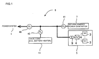
- FIG. 1 is a system configuration diagram showing an example of an interconnected system that includes a power generator that changes in output, and an electric power storage-compensation device.
- An interconnected system 8 shown in FIG. 1 includes a natural-energy power generator 7 (e.g., wind power generator or solar power generator), an electric power storage-compensation device 5, and a local load 11.
- the electric power storage-compensation device 5 includes a sodium-sulfur battery 3 (i.e., a secondary battery that can store power, and can be charged and discharged), a bidirectional converter 4 having a dc/ac conversion function, and a transformer 9.
- the bidirectional converter 4 may include a chopper and an inverter, or may include an inverter, for example.
- the interconnected system 8 includes the natural-energy power generator 7 and the sodium-sulfur battery 3 (electric power storage-compensation device 5).
- One or a plurality of sodium-sulfur batteries 3 included in the electric power storage-compensation device 5 are collectively referred to as "sodium-sulfur battery 3".
- the interconnected system 8 normally includes a heater for the sodium-sulfur battery 3 and other auxiliaries (e.g., computer and lighting device) as the local load 11.
- the interconnected system 8 includes a wattmeter 41 that measures power P A generated by the natural-energy power generator 7.
- P B is power output from the electric power storage-compensation device 5).
- the power direction from the interconnected system 8 to a power system 1 is referred to as a positive direction (+).
- the interconnected system 8 plans a power generation schedule based on predicted natural-energy power generation and the battery level, and supplies power from the interconnected system 8 to the power system 1 according to the power generation schedule. In other words, the interconnected system 8 is controlled so that the power P T measured by the wattmeter 48 coincides with a planned power generation value of the power generation schedule.
- the interconnected system 8 is configured so that the electric power storage-compensation device 5 charges and discharges the sodium-sulfur battery 3 such that the power P B output from the electric power storage-compensation device 5 compensates for a change in power generated by the natural-energy power generator 7 (power P A measured by the wattmeter 41) and power consumed by the local load 11 (power P C measure by the wattmeter 43).
- the power P T measured by the wattmeter 48 and the power P A measured by the wattmeter 41 are input to the electric power storage-compensation device 5, and charging/discharging of the sodium-sulfur battery 3 is controlled based on the input values.
- charging/discharging of the sodium-sulfur battery 3 i.e., power P B
- power P T measure by the wattmeter 48 power output from the interconnected system 8
- the electric power storage-compensation device 5 charges or discharges the sodium-sulfur battery 3 by changing the amount of control (control target value) of the bidirectional converter 4 based on the output (power P A ) from the natural-energy power generator 7 so that power that compensates for a change in output (power P A ) from the natural-energy power generator 7 is input or output. A change in output from the natural-energy power generator 7 is thus absorbed. Since stable and high-quality power can be supplied using the natural-energy power generator 7 and the sodium-sulfur battery 3 (electric power storage-compensation device 5) that discharge only a small amount of carbon dioxide, the interconnected system 8 is a preferable power generation system.
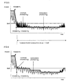
- FIG. 2 shows the horizontal axis in time, and the vertical axis indicates power.
- a thick solid line indicates the power P T , and a broken line indicates P A +P C .
- a region R1 is a region in which the sodium-sulfur battery 3 is discharged (P B >0), and a region R2 is a region in which the sodium-sulfur battery 3 is charged (P B ⁇ 0).
- the sodium-sulfur battery 3 is charged or discharged so that the power P T measured by the wattmeter 48 coincides with the planned power generation value.
- the operation of the sodium-sulfur battery 3 that is included in the electric power storage-compensation device 5 and compensates for a change in output of the power generator is stopped when the planned power generation value is 0 kW or less, and the sum of the power P A generated by the power generator and the local load power P C of the interconnected system has reached a value at which power is supplied to the interconnected system from the power system (P A +P C ⁇ 0 kW), as shown in FIG. 2 .
- the planned power generation value of the interconnected system is set to the sum (P A +P C ) of the power P A generated by the power generator and the local load power P C of the interconnected system.
- the interconnected system 8 is preferably set in the non-power transmission mode when it is impossible to generate power using natural energy for a long time.
- the power P T measured by the wattmeter 48 becomes P A +P C by setting the interconnected system 8 in the non-power transmission mode. Therefore, discharging of the sodium-sulfur battery 3 is stopped (i.e., a decrease in battery level does not occur).
- the planned power generation value is initially set to a given value larger than 0 kW.
- the sodium-sulfur battery 3 is discharged since the power P A +P C is exceeded (before setting the interconnected system 8 in the non-power transmission mode).
- the planned power generation value is set to P A +P C (i.e., the interconnected system 8 is controlled so that the power P T becomes P A +P C ) (i.e., the thick solid line coincides with the broken line) when the planned power generation value is 0 kW or less, and the interconnected system 8 has been set in the non-power transmission mode. Therefore, the sodium-sulfur battery 3 is not charged/discharged.
- the planned power generation value is set to 0 kW when the sum of the power generated by the power generator and the local load power of the interconnected system has temporarily reached a value at which power is supplied to the power system from the interconnected system.
- the planned power generation value is set to 0 kW (the operation of the sodium-sulfur battery 3 is resumed if the operation of the sodium-sulfur battery 3 is halted) when P A +P C has exceeded 0 kW, and the sodium-sulfur battery 3 is charged (see the region R2).
- FIG. 3 is a system configuration diagram showing another example of an interconnected system that includes a power generator that changes in output, and an electric power storage-compensation device.
- An interconnected system 8 shown in FIG. 3 includes the natural-energy power generator 7, the electric power storage-compensation device 5, and the local load 11 in the same manner as in FIG. 1 .
- discharging of the sodium-sulfur battery 3 i.e., power P B
- the operation of the sodium-sulfur battery 3 that is included in the electric power storage-compensation device 5 and compensates for a change in output of the power generator is stopped when the planned power generation value is 0 kW or less, and the sum of the power P A generated by the power generator and the local load power P C of the interconnected system has reached a value at which power is supplied to the interconnected system from the power system (P A +P C ⁇ 0 kW).
- the planned power value of the power generation schedule of the interconnected system is set to the sum of the power P A generated by the power generator and the local load power P C of the interconnected system (non-power transmission mode).
- the operation of the sodium-sulfur battery is stopped, or the planned power generation value of the power generation schedule of the interconnected system is set to non-power transmission mode where the sum of the power generated by the power generator and the local load power of the interconnected system, when the planned power generation value is 0 kW or less.
- a decrease in battery level of the sodium-sulfur battery can be suppressed by setting the interconnected system in the non-power transmission mode.
- the method of controlling a secondary battery according to the present invention may be used as a method of controlling an interconnected system that supplies power to a power system, and includes a power generator that generates power using natural energy (e.g., wind, solar power, or geothermal energy) and changes in output, and an electric power storage-compensation device that includes a plurality of sodium-sulfur batteries.
- natural energy e.g., wind, solar power, or geothermal energy
- an electric power storage-compensation device that includes a plurality of sodium-sulfur batteries.
Abstract
Description
- The present invention relates to a method of controlling an interconnected system that supplies power to a power system, and includes a power generator (e.g., wind power generator) that changes in output, in combination with an electric power storage-compensation device that includes a sodium-sulfur battery.
- In recent years, a natural-energy power generator that generates power using wind, solar power, geothermal energy, or the like has attracted attention, and has been put to practical use. A natural-energy power generator is a clean power generator that utilizes an inexhaustible natural energy source instead of limited resources (e.g., petroleum), and can suppress carbon dioxide emissions. Therefore, companies, autonomies, and the like have increasingly employed a natural-energy power generator in view of prevention of global warming.
- However, since the amount of natural energy obtained varies from hour to hour, a natural-energy power generator inevitably changes in output. This is an obstacle to widespread use of a natural-energy power generator. Therefore, when employing a natural-energy power generator, it is preferable to construct an interconnected (power generation) system by combining the natural-energy power generator with an electric power storage-compensation device that mainly includes a plurality of secondary batteries.
- In particular, a sodium-sulfur battery among the other secondary batteries has a high energy density, achieves a high output within a short time, and exhibits a rapid response. Therefore, a sodium-sulfur battery may suitably be used to compensate for a change in output of a natural-energy power generator that may occur of the order of several hundred milliseconds to several seconds by providing a bidirectional converter that controls charging and discharging in combination with the sodium-sulfur battery. In other words, an interconnected system that includes a natural-energy power generator and an electric power storage-compensation device that includes a plurality of sodium-sulfur batteries is a desirable power generation system.
- Since a natural-energy power generator changes in output, an electric power storage-compensation device frequently receives and outputs power. That is, a sodium-sulfur battery that is included in the electric power storage-compensation device is repeatedly charged and discharged. This makes it difficult to accurately manage the battery level of the sodium-sulfur battery, so that it may suddenly become impossible to charge or discharge the sodium-sulfur battery (e.g., the operation of the sodium-sulfur battery stops when compensating for a change in output of the natural-energy power generator). Various methods have been disclosed to control a sodium-sulfur battery that is included in an electric power storage-compensation device (see
JP-A-2003-317808 - The sodium-sulfur battery that is included in the electric power storage-compensation device of the interconnected system suppresses or eliminates a change in power generation schedule that is designated manually or using a computer or the like taking account of a change in natural energy power generation. The interconnected system plans a power generation schedule based on predicted natural-energy power generation and the battery level, and supplies power from the interconnected system to the power system according to the power generation schedule. When it is impossible to generate power using natural energy (e.g., no wind) for a long time, the planned power generation value is normally set to 0 kW (i.e., power is not supplied to the power system). In this case, however, it is necessary to supply power to the local load of the interconnected system. Therefore, the sodium-sulfur battery is discharged to supply power to the local load, so that the battery level decreases.
- For example, when using an interconnected
system 8 shown inFIG. 1 that includes a wind power generator 7 (natural-energy power generator), an electric power storage-compensation device 5, and alocal load 11, in the case where the planned power generation value is 0 kW (seeFIG. 4 ) (i.e., power PT (thick solid line inFIG. 4 ) measured by awattmeter 48 is 0 kW), a sodium-sulfur battery 3 is charged when power PA+PC (broken line inFIG. 4 ) has exceeded 0 kW. On the other hand, when the power PA+PC is less than 0 kW, the sodium-sulfur battery 3 is discharged to compensate for lack of power, so that the battery level decreases. - In this case, the amount of power to be discharged can be reduced (i.e., a decrease in battery level can be suppressed) by setting the planned power generation value to a value at which power is supplied to the interconnected system from the power system 1 (see
FIG. 5 ). In this case, the interconnectedsystem 8 is charged from thepower system 1. In other words, theinterconnected system 8 which should charge power to thepower system 1 is supplied power from thepower system 1. This situation is not preferred. - When the planned power generation value is set to a value at which power is supplied to the interconnected system from the power system 1 (i.e., power PT is set to be a negative value), the sodium-sulfur battery is charged when the power PA+PC has exceeded the planned power generation value. However, when the power PA+PC has exceeded the planned power generation value, but is less than 0 kW, the sodium-
sulfur battery 3 is charged from thepower system 1. On the other hand, when the power PA+PC is less than the planned power generation value, the sodium-sulfur battery 3 is discharged, so that the battery level decreases. - As shown in
FIG 6 , power generated using natural energy and the local load power may be monitored, and a situation in which the sodium-sulfur battery 3 is charged from the power system may be prevented by changing the power generation schedule. However, this increases burden on the operator. - The present invention was conceived in view of the above problems. An object of the present invention is to provide a method of controlling an interconnected system that can suppress a decrease in battery level of a sodium-sulfur battery when it is impossible to generate power using natural energy for a long time.
- The inventors of the present invention conducted extensive studies in order to achieve the above object. As a result, the inventors found that the above object can be achieved by stopping the operation of the sodium-sulfur battery, or setting the planned power generation value of the power generation schedule of the interconnected system to the sum of power generated by the power generator and the local load power of the interconnected system. This finding has led to the completion of the present invention. Specifically, the present invention provides the following method of controlling an interconnected system.
- [1] A method of controlling an interconnected system that supplies power to a power system, and includes a power generator that changes in output, and an electric power storage-compensation device, the method comprising stopping operation of a sodium-sulfur battery that is included in the electric power storage-compensation device and compensates for a change in output of the power generator, or setting the interconnected system in a non-power transmission mode in which a planned power generation value of a power generation schedule of the interconnected system is set to the sum of power generated by the power generator and local load power of the interconnected system, when the planned power generation value is 0 kW or less, and the sum of the power generated by the power generator and the local load power of the interconnected system has reached a value at which power is supplied to the interconnected system from the power system.
- [2] The method according to [1], wherein the planned power generation value is set to 0 kW in the non-power transmission mode when the sum of the power generated by the power generator and the local load power of the interconnected system has temporarily reached a value at which power is supplied to the power system from the interconnected system.
- According to the method of controlling an interconnected system according to the present invention, when it is impossible to generate power using natural energy for a long time, a decrease in battery level of the sodium-sulfur battery can be suppressed by stopping the operation of the sodium-sulfur battery, or setting the planned power generation value of the power generation schedule of the interconnected system to the sum of the power generated by the power generator and the local load power of the interconnected system (i.e., setting the interconnected system in the non-power transmission mode). Therefore, power generated using natural energy can be effectively utilized.
-
-
FIG. 1 is a system configuration diagram showing an example of an interconnected system that includes a power generator that changes in output, and an electric power storage-compensation device. -
FIG. 2 is a graph schematically showing an example of a method of controlling an interconnected system according to the present invention. -
FIG. 3 is a system configuration diagram showing another example of an interconnected system that includes a power generator that changes in output, and an electric power storage-compensation device. -
FIG. 4 is a graph schematically showing an example of a method of controlling an interconnected system according to a comparative example. -
FIG. 5 is a graph schematically showing an example of a method of controlling an interconnected system according to another comparative example. -
FIG. 6 is a graph schematically showing an example of a method of controlling an interconnected system according to yet another comparative example. - Exemplary embodiments of the present invention are described below. Note that the present invention is not limited to the following embodiments. Various modifications and improvements of the design may be made based on the common knowledge of a person having ordinary skill in the art without departing from the scope of the present invention.
- An interconnected system is described below.
FIG. 1 is a system configuration diagram showing an example of an interconnected system that includes a power generator that changes in output, and an electric power storage-compensation device. Aninterconnected system 8 shown inFIG. 1 includes a natural-energy power generator 7 (e.g., wind power generator or solar power generator), an electric power storage-compensation device 5, and alocal load 11. The electric power storage-compensation device 5 includes a sodium-sulfur battery 3 (i.e., a secondary battery that can store power, and can be charged and discharged), abidirectional converter 4 having a dc/ac conversion function, and atransformer 9. Thebidirectional converter 4 may include a chopper and an inverter, or may include an inverter, for example. - The interconnected
system 8 includes the natural-energy power generator 7 and the sodium-sulfur battery 3 (electric power storage-compensation device 5). One or a plurality of sodium-sulfur batteries 3 included in the electric power storage-compensation device 5 are collectively referred to as "sodium-sulfur battery 3". The interconnectedsystem 8 normally includes a heater for the sodium-sulfur battery 3 and other auxiliaries (e.g., computer and lighting device) as thelocal load 11. - As shown in
FIG. 1 , theinterconnected system 8 includes awattmeter 41 that measures power PA generated by the natural-energy power generator 7. The interconnectedsystem 8 also includes awattmeter 43 that measures power PC consumed by the local load, and awattmeter 48 that measures power PA+PB+PC (=PT) (where, PB is power output from the electric power storage-compensation device 5). The power direction from theinterconnected system 8 to apower system 1 is referred to as a positive direction (+). - The
interconnected system 8 plans a power generation schedule based on predicted natural-energy power generation and the battery level, and supplies power from theinterconnected system 8 to thepower system 1 according to the power generation schedule. In other words, theinterconnected system 8 is controlled so that the power PT measured by thewattmeter 48 coincides with a planned power generation value of the power generation schedule. - Therefore, the
interconnected system 8 is configured so that the electric power storage-compensation device 5 charges and discharges the sodium-sulfur battery 3 such that the power PB output from the electric power storage-compensation device 5 compensates for a change in power generated by the natural-energy power generator 7 (power PA measured by the wattmeter 41) and power consumed by the local load 11 (power PC measure by the wattmeter 43). The power PT measured by thewattmeter 48 and the power PA measured by thewattmeter 41 are input to the electric power storage-compensation device 5, and charging/discharging of the sodium-sulfur battery 3 is controlled based on the input values. Specifically, charging/discharging of the sodium-sulfur battery 3 (i.e., power PB) is controlled so that power output from the interconnected system 8 (power PT measure by the wattmeter 48) satisfies the planned power generation value (i.e., PT=PA+PB+PC). This makes it possible to supply the power PT output from theinterconnected system 8 as a whole (hereinafter may be referred to as "total power PT") to thepower system 1 as stable and high-quality power. Note that thelocal load 11 includes a heater for the sodium-sulfur battery 3, a control power supply, and the like. - In the
interconnected system 8, the electric power storage-compensation device 5 charges the sodium-sulfur battery 3 based on a change in power PA generated by the natural-energy power generator 7. Specifically, charging/discharging of the sodium-sulfur battery 3 (i.e., power PB) is controlled so that the power PB satisfies the relationship PB=PT-(PA+PC) to compensate for a change in power PA. This makes it possible to adjust the power PT output from theinterconnected system 8 as a whole to the planned power generation value. - When charging or discharging the sodium-
sulfur battery 3, the electric power storage-compensation device 5 charges or discharges the sodium-sulfur battery 3 by changing the amount of control (control target value) of thebidirectional converter 4 based on the output (power PA) from the natural-energy power generator 7 so that power that compensates for a change in output (power PA) from the natural-energy power generator 7 is input or output. A change in output from the natural-energy power generator 7 is thus absorbed. Since stable and high-quality power can be supplied using the natural-energy power generator 7 and the sodium-sulfur battery 3 (electric power storage-compensation device 5) that discharge only a small amount of carbon dioxide, theinterconnected system 8 is a preferable power generation system. - A power control method for the sodium-
sulfur battery 3 when adjusting power supplied to the power system from theinterconnected system 8 shown inFIG. 1 to the planned power generation value (set value) is described below with reference toFIG. 2 . InFIG. 2 , the horizontal axis indicates time, and the vertical axis indicates power. A thick solid line indicates the power PT, and a broken line indicates PA+PC.FIG. 2 shows the case where theinterconnected system 8 is set in a non-power transmission mode when the planned power generation value=0 kW and PA+PC<0 (see the enlarged view). A region R1 is a region in which the sodium-sulfur battery 3 is discharged (PB>0), and a region R2 is a region in which the sodium-sulfur battery 3 is charged (PB<0). - In the
interconnected system 8, the sodium-sulfur battery 3 is charged or discharged so that the power PT measured by thewattmeter 48 coincides with the planned power generation value. In the method of controlling an interconnected system according to the present invention, the operation of the sodium-sulfur battery 3 that is included in the electric power storage-compensation device 5 and compensates for a change in output of the power generator is stopped when the planned power generation value is 0 kW or less, and the sum of the power PA generated by the power generator and the local load power PC of the interconnected system has reached a value at which power is supplied to the interconnected system from the power system (PA+PC<0 kW), as shown inFIG. 2 . Alternatively, the planned power generation value of the interconnected system is set to the sum (PA+PC) of the power PA generated by the power generator and the local load power PC of the interconnected system. Theinterconnected system 8 is preferably set in the non-power transmission mode when it is impossible to generate power using natural energy for a long time. The power PT measured by thewattmeter 48 becomes PA+PC by setting theinterconnected system 8 in the non-power transmission mode. Therefore, discharging of the sodium-sulfur battery 3 is stopped (i.e., a decrease in battery level does not occur). - In
FIG. 2 , the planned power generation value is initially set to a given value larger than 0 kW. In the region R1, the sodium-sulfur battery 3 is discharged since the power PA+PC is exceeded (before setting theinterconnected system 8 in the non-power transmission mode). When it is impossible to generate power using natural energy for a long time, the planned power generation value is set to PA+PC (i.e., theinterconnected system 8 is controlled so that the power PT becomes PA+PC) (i.e., the thick solid line coincides with the broken line) when the planned power generation value is 0 kW or less, and theinterconnected system 8 has been set in the non-power transmission mode. Therefore, the sodium-sulfur battery 3 is not charged/discharged. The planned power generation value is set to 0 kW when the sum of the power generated by the power generator and the local load power of the interconnected system has temporarily reached a value at which power is supplied to the power system from the interconnected system. In other words, the planned power generation value is set to 0 kW (the operation of the sodium-sulfur battery 3 is resumed if the operation of the sodium-sulfur battery 3 is halted) when PA+PC has exceeded 0 kW, and the sodium-sulfur battery 3 is charged (see the region R2). -
FIG. 3 is a system configuration diagram showing another example of an interconnected system that includes a power generator that changes in output, and an electric power storage-compensation device. Aninterconnected system 8 shown inFIG. 3 includes the natural-energy power generator 7, the electric power storage-compensation device 5, and thelocal load 11 in the same manner as inFIG. 1 . - As shown in
FIG. 3 , theinterconnected system 8 also includes awattmeter 46 that measures power PA+PC (=PAC) (where, PA is power output from the natural-energy power generator 7, and PC is power consumed by the local load 11). Theinterconnected system 8 also includes awattmeter 48 that measures power PA+PB+PC (=PT) (where, PB is power output from the electric power storage-compensation device 5). - In this embodiment, discharging of the sodium-sulfur battery 3 (i.e., power PB) is controlled so that the power PT measure by the
wattmeter 48 satisfies the planned power generation value (i.e., PT=PA+PB+PC) set by the power generation schedule in the same manner as in the embodiment described with reference toFIGs. 1 and2 . The operation of the sodium-sulfur battery 3 that is included in the electric power storage-compensation device 5 and compensates for a change in output of the power generator is stopped when the planned power generation value is 0 kW or less, and the sum of the power PA generated by the power generator and the local load power PC of the interconnected system has reached a value at which power is supplied to the interconnected system from the power system (PA+PC<0 kW). Alternatively, the planned power value of the power generation schedule of the interconnected system is set to the sum of the power PA generated by the power generator and the local load power PC of the interconnected system (non-power transmission mode). - According to the method of controlling an interconnected system according to the present invention, when it is impossible to generate power using natural energy for a long time, the operation of the sodium-sulfur battery is stopped, or the planned power generation value of the power generation schedule of the interconnected system is set to non-power transmission mode where the sum of the power generated by the power generator and the local load power of the interconnected system, when the planned power generation value is 0 kW or less. A decrease in battery level of the sodium-sulfur battery can be suppressed by setting the interconnected system in the non-power transmission mode.
- The method of controlling a secondary battery according to the present invention may be used as a method of controlling an interconnected system that supplies power to a power system, and includes a power generator that generates power using natural energy (e.g., wind, solar power, or geothermal energy) and changes in output, and an electric power storage-compensation device that includes a plurality of sodium-sulfur batteries.
- 1: power system, 3: sodium-sulfur battery, 4: bidirectional converter, 5: electric power storage-compensation device, 7: wind power generator, 8: interconnected system, 9: transformer, 11: local load, 41, 43, 46, 48: wattmeter
Claims (2)
- A method of controlling an interconnected system that supplies power to a power system, and includes a power generator that changes in output, and an electric power storage-compensation device,
the method comprising stopping operation of a sodium-sulfur battery that is included in the electric power storage-compensation device and compensates for a change in output of the power generator, or setting the interconnected system in a non-power transmission mode in which a planned power generation value of a power generation schedule of the interconnected system is set to the sum of power generated by the power generator and local load power of the interconnected system,
when the planned power generation value is 0 kW or less, and the sum of the power generated by the power generator and the local load power of the interconnected system has reached a value at which power is supplied to the interconnected system from the power system. - The method according to claim 1, wherein the planned power generation value is set to 0 kW in the non-power transmission mode when the sum of the power generated by the power generator and the local load power of the interconnected system has temporarily reached a value at which power is supplied to the power system from the interconnected system.
Applications Claiming Priority (2)
| Application Number | Priority Date | Filing Date | Title |
|---|---|---|---|
| US10116908P | 2008-09-30 | 2008-09-30 | |
| PCT/JP2009/066613 WO2010038666A1 (en) | 2008-09-30 | 2009-09-25 | Method for controlling interconnection system |
Publications (3)
| Publication Number | Publication Date |
|---|---|
| EP2330711A1 true EP2330711A1 (en) | 2011-06-08 |
| EP2330711A4 EP2330711A4 (en) | 2017-06-21 |
| EP2330711B1 EP2330711B1 (en) | 2020-10-21 |
Family
ID=42073430
Family Applications (1)
| Application Number | Title | Priority Date | Filing Date |
|---|---|---|---|
| EP09817699.3A Active EP2330711B1 (en) | 2008-09-30 | 2009-09-25 | Method for controlling interconnection system |
Country Status (5)
| Country | Link |
|---|---|
| US (1) | US8384242B2 (en) |
| EP (1) | EP2330711B1 (en) |
| JP (1) | JP5543355B2 (en) |
| CN (1) | CN102144345B (en) |
| WO (1) | WO2010038666A1 (en) |
Cited By (1)
| Publication number | Priority date | Publication date | Assignee | Title |
|---|---|---|---|---|
| CN106640523A (en) * | 2016-10-20 | 2017-05-10 | 湖南大学 | Storage battery charge and discharge control strategy of vertical-axis wind power generation system |
Families Citing this family (3)
| Publication number | Priority date | Publication date | Assignee | Title |
|---|---|---|---|---|
| JP5964254B2 (en) * | 2013-01-18 | 2016-08-03 | 三菱重工業株式会社 | Output leveling system and method for distributed power supply and distributed power supply system |
| JP6648614B2 (en) * | 2016-04-05 | 2020-02-14 | オムロン株式会社 | Power storage device |
| ES2874544T3 (en) * | 2016-10-14 | 2021-11-05 | Toshiba Mitsubishi Elec Ind | Power conversion system, power supply system, and power conversion apparatus |
Family Cites Families (11)
| Publication number | Priority date | Publication date | Assignee | Title |
|---|---|---|---|---|
| JPH10201129A (en) * | 1996-12-27 | 1998-07-31 | Japan Storage Battery Co Ltd | Power generation installation making use of solar energy |
| DE19948196A1 (en) * | 1999-10-06 | 2001-05-17 | Aloys Wobben | Process for operating a wind farm |
| JP2001298872A (en) * | 2000-04-13 | 2001-10-26 | Sumitomo Electric Ind Ltd | Power storage system |
| JP2001327083A (en) * | 2000-05-18 | 2001-11-22 | Ngk Insulators Ltd | Power storage and compensation system by high- temperature secondary battery |
| JP2003317808A (en) | 2002-04-22 | 2003-11-07 | Ngk Insulators Ltd | Charge/discharge control method of sodium - sulfur battery, and power preservation device and power compensation device |
| JP3964852B2 (en) * | 2003-10-22 | 2007-08-22 | 大阪瓦斯株式会社 | Distributed power generation system |
| US20070100506A1 (en) * | 2005-10-31 | 2007-05-03 | Ralph Teichmann | System and method for controlling power flow of electric power generation system |
| JP5073258B2 (en) * | 2006-09-27 | 2012-11-14 | 日本碍子株式会社 | Control method of sodium-sulfur battery |
| JP4796974B2 (en) | 2007-01-26 | 2011-10-19 | 株式会社日立産機システム | Hybrid system of wind power generator and power storage device, wind power generation system, power control device |
| JP5096018B2 (en) * | 2007-02-23 | 2012-12-12 | 日本碍子株式会社 | Sodium-sulfur battery control system |
| JP4949902B2 (en) * | 2007-03-16 | 2012-06-13 | 日本碍子株式会社 | Secondary battery power control method |
-
2009
- 2009-09-25 WO PCT/JP2009/066613 patent/WO2010038666A1/en active Application Filing
- 2009-09-25 EP EP09817699.3A patent/EP2330711B1/en active Active
- 2009-09-25 JP JP2010531825A patent/JP5543355B2/en active Active
- 2009-09-25 CN CN200980134631XA patent/CN102144345B/en active Active
-
2011
- 2011-02-28 US US13/036,257 patent/US8384242B2/en active Active
Non-Patent Citations (1)
| Title |
|---|
| See references of WO2010038666A1 * |
Cited By (1)
| Publication number | Priority date | Publication date | Assignee | Title |
|---|---|---|---|---|
| CN106640523A (en) * | 2016-10-20 | 2017-05-10 | 湖南大学 | Storage battery charge and discharge control strategy of vertical-axis wind power generation system |
Also Published As
| Publication number | Publication date |
|---|---|
| EP2330711A4 (en) | 2017-06-21 |
| CN102144345A (en) | 2011-08-03 |
| CN102144345B (en) | 2013-10-16 |
| JP5543355B2 (en) | 2014-07-09 |
| US8384242B2 (en) | 2013-02-26 |
| EP2330711B1 (en) | 2020-10-21 |
| JPWO2010038666A1 (en) | 2012-03-01 |
| WO2010038666A1 (en) | 2010-04-08 |
| US20110198930A1 (en) | 2011-08-18 |
Similar Documents
| Publication | Publication Date | Title |
|---|---|---|
| US9000712B2 (en) | Secondary battery power control method | |
| JP6082886B2 (en) | Power adjustment apparatus and power adjustment method | |
| JP4369450B2 (en) | Power supply system | |
| US20040070280A1 (en) | Output suppressing method of a plurality of dispersed power sources and dispersed power source managing system | |
| JP6455661B2 (en) | Independent operation system | |
| JP2017011948A (en) | Power distribution device | |
| US10749346B2 (en) | Power management system | |
| WO2011051772A1 (en) | Direct-current power supply device and direct-current power supply system | |
| US8384242B2 (en) | Method for controlling interconnection system | |
| WO2010038663A1 (en) | Method for controlling sodium-sulfur batteries | |
| JP6480212B2 (en) | Power conversion device, power management system, and power conversion method | |
| EP2330677A1 (en) | Method for controlling sodium-sulfur battery | |
| JP2020523971A (en) | Energy storage system | |
| WO2012043636A1 (en) | Power supply system | |
| WO2015111144A1 (en) | Power supply system and energy management system used in same | |
| US8598839B2 (en) | Method for controlling sodium-sulfur battery | |
| JP2016116428A (en) | Autonomous operation system for distributed power source | |
| KR101737461B1 (en) | System for obtaining a driving power source to the power generation of the solar cell and method therefor | |
| EP2339685B1 (en) | Method for controlling sodium-sulfur battery | |
| KR102338490B1 (en) | An energy storage system possible for uninterruptible power supply | |
| KR20170135008A (en) | Driving Control Method Of Tidal current Power System | |
| JP2015231327A (en) | DC power supply system and rectifier | |
| Anand et al. | Power management control for solar photovoltaic based DC system | |
| WO2021039678A1 (en) | Direct current power supply device | |
| JP2019030160A (en) | Distribution-type power supply system |
Legal Events
| Date | Code | Title | Description |
|---|---|---|---|
| PUAI | Public reference made under article 153(3) epc to a published international application that has entered the european phase |
Free format text: ORIGINAL CODE: 0009012 |
|
| 17P | Request for examination filed |
Effective date: 20110328 |
|
| AK | Designated contracting states |
Kind code of ref document: A1 Designated state(s): AT BE BG CH CY CZ DE DK EE ES FI FR GB GR HR HU IE IS IT LI LT LU LV MC MK MT NL NO PL PT RO SE SI SK SM TR |
|
| AX | Request for extension of the european patent |
Extension state: AL BA RS |
|
| DAX | Request for extension of the european patent (deleted) | ||
| RA4 | Supplementary search report drawn up and despatched (corrected) |
Effective date: 20170518 |
|
| RIC1 | Information provided on ipc code assigned before grant |
Ipc: H02J 3/38 20060101ALI20170512BHEP Ipc: H02J 3/32 20060101AFI20170512BHEP Ipc: H02J 7/34 20060101ALI20170512BHEP |
|
| STAA | Information on the status of an ep patent application or granted ep patent |
Free format text: STATUS: EXAMINATION IS IN PROGRESS |
|
| 17Q | First examination report despatched |
Effective date: 20180524 |
|
| GRAP | Despatch of communication of intention to grant a patent |
Free format text: ORIGINAL CODE: EPIDOSNIGR1 |
|
| STAA | Information on the status of an ep patent application or granted ep patent |
Free format text: STATUS: GRANT OF PATENT IS INTENDED |
|
| INTG | Intention to grant announced |
Effective date: 20200421 |
|
| GRAS | Grant fee paid |
Free format text: ORIGINAL CODE: EPIDOSNIGR3 |
|
| GRAA | (expected) grant |
Free format text: ORIGINAL CODE: 0009210 |
|
| STAA | Information on the status of an ep patent application or granted ep patent |
Free format text: STATUS: THE PATENT HAS BEEN GRANTED |
|
| AK | Designated contracting states |
Kind code of ref document: B1 Designated state(s): AT BE BG CH CY CZ DE DK EE ES FI FR GB GR HR HU IE IS IT LI LT LU LV MC MK MT NL NO PL PT RO SE SI SK SM TR |
|
| REG | Reference to a national code |
Ref country code: GB Ref legal event code: FG4D |
|
| REG | Reference to a national code |
Ref country code: CH Ref legal event code: EP |
|
| REG | Reference to a national code |
Ref country code: DE Ref legal event code: R096 Ref document number: 602009062948 Country of ref document: DE |
|
| REG | Reference to a national code |
Ref country code: IE Ref legal event code: FG4D |
|
| REG | Reference to a national code |
Ref country code: AT Ref legal event code: REF Ref document number: 1326827 Country of ref document: AT Kind code of ref document: T Effective date: 20201115 |
|
| REG | Reference to a national code |
Ref country code: AT Ref legal event code: MK05 Ref document number: 1326827 Country of ref document: AT Kind code of ref document: T Effective date: 20201021 |
|
| REG | Reference to a national code |
Ref country code: NL Ref legal event code: MP Effective date: 20201021 |
|
| PG25 | Lapsed in a contracting state [announced via postgrant information from national office to epo] |
Ref country code: GR Free format text: LAPSE BECAUSE OF FAILURE TO SUBMIT A TRANSLATION OF THE DESCRIPTION OR TO PAY THE FEE WITHIN THE PRESCRIBED TIME-LIMIT Effective date: 20210122 Ref country code: FI Free format text: LAPSE BECAUSE OF FAILURE TO SUBMIT A TRANSLATION OF THE DESCRIPTION OR TO PAY THE FEE WITHIN THE PRESCRIBED TIME-LIMIT Effective date: 20201021 Ref country code: PT Free format text: LAPSE BECAUSE OF FAILURE TO SUBMIT A TRANSLATION OF THE DESCRIPTION OR TO PAY THE FEE WITHIN THE PRESCRIBED TIME-LIMIT Effective date: 20210222 Ref country code: NO Free format text: LAPSE BECAUSE OF FAILURE TO SUBMIT A TRANSLATION OF THE DESCRIPTION OR TO PAY THE FEE WITHIN THE PRESCRIBED TIME-LIMIT Effective date: 20210121 Ref country code: NL Free format text: LAPSE BECAUSE OF FAILURE TO SUBMIT A TRANSLATION OF THE DESCRIPTION OR TO PAY THE FEE WITHIN THE PRESCRIBED TIME-LIMIT Effective date: 20201021 |
|
| REG | Reference to a national code |
Ref country code: LT Ref legal event code: MG4D |
|
| PG25 | Lapsed in a contracting state [announced via postgrant information from national office to epo] |
Ref country code: LV Free format text: LAPSE BECAUSE OF FAILURE TO SUBMIT A TRANSLATION OF THE DESCRIPTION OR TO PAY THE FEE WITHIN THE PRESCRIBED TIME-LIMIT Effective date: 20201021 Ref country code: SE Free format text: LAPSE BECAUSE OF FAILURE TO SUBMIT A TRANSLATION OF THE DESCRIPTION OR TO PAY THE FEE WITHIN THE PRESCRIBED TIME-LIMIT Effective date: 20201021 Ref country code: PL Free format text: LAPSE BECAUSE OF FAILURE TO SUBMIT A TRANSLATION OF THE DESCRIPTION OR TO PAY THE FEE WITHIN THE PRESCRIBED TIME-LIMIT Effective date: 20201021 Ref country code: IS Free format text: LAPSE BECAUSE OF FAILURE TO SUBMIT A TRANSLATION OF THE DESCRIPTION OR TO PAY THE FEE WITHIN THE PRESCRIBED TIME-LIMIT Effective date: 20210221 Ref country code: ES Free format text: LAPSE BECAUSE OF FAILURE TO SUBMIT A TRANSLATION OF THE DESCRIPTION OR TO PAY THE FEE WITHIN THE PRESCRIBED TIME-LIMIT Effective date: 20201021 Ref country code: AT Free format text: LAPSE BECAUSE OF FAILURE TO SUBMIT A TRANSLATION OF THE DESCRIPTION OR TO PAY THE FEE WITHIN THE PRESCRIBED TIME-LIMIT Effective date: 20201021 Ref country code: BG Free format text: LAPSE BECAUSE OF FAILURE TO SUBMIT A TRANSLATION OF THE DESCRIPTION OR TO PAY THE FEE WITHIN THE PRESCRIBED TIME-LIMIT Effective date: 20210121 |
|
| PG25 | Lapsed in a contracting state [announced via postgrant information from national office to epo] |
Ref country code: HR Free format text: LAPSE BECAUSE OF FAILURE TO SUBMIT A TRANSLATION OF THE DESCRIPTION OR TO PAY THE FEE WITHIN THE PRESCRIBED TIME-LIMIT Effective date: 20201021 |
|
| REG | Reference to a national code |
Ref country code: DE Ref legal event code: R097 Ref document number: 602009062948 Country of ref document: DE |
|
| PG25 | Lapsed in a contracting state [announced via postgrant information from national office to epo] |
Ref country code: LT Free format text: LAPSE BECAUSE OF FAILURE TO SUBMIT A TRANSLATION OF THE DESCRIPTION OR TO PAY THE FEE WITHIN THE PRESCRIBED TIME-LIMIT Effective date: 20201021 Ref country code: RO Free format text: LAPSE BECAUSE OF FAILURE TO SUBMIT A TRANSLATION OF THE DESCRIPTION OR TO PAY THE FEE WITHIN THE PRESCRIBED TIME-LIMIT Effective date: 20201021 Ref country code: SK Free format text: LAPSE BECAUSE OF FAILURE TO SUBMIT A TRANSLATION OF THE DESCRIPTION OR TO PAY THE FEE WITHIN THE PRESCRIBED TIME-LIMIT Effective date: 20201021 Ref country code: SM Free format text: LAPSE BECAUSE OF FAILURE TO SUBMIT A TRANSLATION OF THE DESCRIPTION OR TO PAY THE FEE WITHIN THE PRESCRIBED TIME-LIMIT Effective date: 20201021 Ref country code: EE Free format text: LAPSE BECAUSE OF FAILURE TO SUBMIT A TRANSLATION OF THE DESCRIPTION OR TO PAY THE FEE WITHIN THE PRESCRIBED TIME-LIMIT Effective date: 20201021 Ref country code: CZ Free format text: LAPSE BECAUSE OF FAILURE TO SUBMIT A TRANSLATION OF THE DESCRIPTION OR TO PAY THE FEE WITHIN THE PRESCRIBED TIME-LIMIT Effective date: 20201021 |
|
| PLBE | No opposition filed within time limit |
Free format text: ORIGINAL CODE: 0009261 |
|
| STAA | Information on the status of an ep patent application or granted ep patent |
Free format text: STATUS: NO OPPOSITION FILED WITHIN TIME LIMIT |
|
| PG25 | Lapsed in a contracting state [announced via postgrant information from national office to epo] |
Ref country code: DK Free format text: LAPSE BECAUSE OF FAILURE TO SUBMIT A TRANSLATION OF THE DESCRIPTION OR TO PAY THE FEE WITHIN THE PRESCRIBED TIME-LIMIT Effective date: 20201021 |
|
| 26N | No opposition filed |
Effective date: 20210722 |
|
| PG25 | Lapsed in a contracting state [announced via postgrant information from national office to epo] |
Ref country code: IT Free format text: LAPSE BECAUSE OF FAILURE TO SUBMIT A TRANSLATION OF THE DESCRIPTION OR TO PAY THE FEE WITHIN THE PRESCRIBED TIME-LIMIT Effective date: 20201021 |
|
| PG25 | Lapsed in a contracting state [announced via postgrant information from national office to epo] |
Ref country code: SI Free format text: LAPSE BECAUSE OF FAILURE TO SUBMIT A TRANSLATION OF THE DESCRIPTION OR TO PAY THE FEE WITHIN THE PRESCRIBED TIME-LIMIT Effective date: 20201021 |
|
| REG | Reference to a national code |
Ref country code: CH Ref legal event code: PL |
|
| REG | Reference to a national code |
Ref country code: BE Ref legal event code: MM Effective date: 20210930 |
|
| PG25 | Lapsed in a contracting state [announced via postgrant information from national office to epo] |
Ref country code: IS Free format text: LAPSE BECAUSE OF FAILURE TO SUBMIT A TRANSLATION OF THE DESCRIPTION OR TO PAY THE FEE WITHIN THE PRESCRIBED TIME-LIMIT Effective date: 20210221 Ref country code: MC Free format text: LAPSE BECAUSE OF FAILURE TO SUBMIT A TRANSLATION OF THE DESCRIPTION OR TO PAY THE FEE WITHIN THE PRESCRIBED TIME-LIMIT Effective date: 20201021 |
|
| PG25 | Lapsed in a contracting state [announced via postgrant information from national office to epo] |
Ref country code: LU Free format text: LAPSE BECAUSE OF NON-PAYMENT OF DUE FEES Effective date: 20210925 Ref country code: IE Free format text: LAPSE BECAUSE OF NON-PAYMENT OF DUE FEES Effective date: 20210925 Ref country code: FR Free format text: LAPSE BECAUSE OF NON-PAYMENT OF DUE FEES Effective date: 20210930 Ref country code: BE Free format text: LAPSE BECAUSE OF NON-PAYMENT OF DUE FEES Effective date: 20210930 |
|
| PG25 | Lapsed in a contracting state [announced via postgrant information from national office to epo] |
Ref country code: LI Free format text: LAPSE BECAUSE OF NON-PAYMENT OF DUE FEES Effective date: 20210930 Ref country code: CH Free format text: LAPSE BECAUSE OF NON-PAYMENT OF DUE FEES Effective date: 20210930 |
|
| PG25 | Lapsed in a contracting state [announced via postgrant information from national office to epo] |
Ref country code: HU Free format text: LAPSE BECAUSE OF FAILURE TO SUBMIT A TRANSLATION OF THE DESCRIPTION OR TO PAY THE FEE WITHIN THE PRESCRIBED TIME-LIMIT; INVALID AB INITIO Effective date: 20090925 Ref country code: CY Free format text: LAPSE BECAUSE OF FAILURE TO SUBMIT A TRANSLATION OF THE DESCRIPTION OR TO PAY THE FEE WITHIN THE PRESCRIBED TIME-LIMIT Effective date: 20201021 |
|
| PGFP | Annual fee paid to national office [announced via postgrant information from national office to epo] |
Ref country code: GB Payment date: 20230803 Year of fee payment: 15 |
|
| PGFP | Annual fee paid to national office [announced via postgrant information from national office to epo] |
Ref country code: DE Payment date: 20230802 Year of fee payment: 15 |