EP2330402B1 - Method and apparatus for desorption of a blood sample from a medical test sheet - Google Patents
Method and apparatus for desorption of a blood sample from a medical test sheet Download PDFInfo
- Publication number
- EP2330402B1 EP2330402B1 EP09177613.8A EP09177613A EP2330402B1 EP 2330402 B1 EP2330402 B1 EP 2330402B1 EP 09177613 A EP09177613 A EP 09177613A EP 2330402 B1 EP2330402 B1 EP 2330402B1
- Authority
- EP
- European Patent Office
- Prior art keywords
- test sheet
- clamping
- clamping heads
- desorption
- sheet
- Prior art date
- Legal status (The legal status is an assumption and is not a legal conclusion. Google has not performed a legal analysis and makes no representation as to the accuracy of the status listed.)
- Active
Links
- 239000008280 blood Substances 0.000 title claims description 73
- 210000004369 blood Anatomy 0.000 title claims description 73
- 238000003795 desorption Methods 0.000 title claims description 58
- 238000000034 method Methods 0.000 title claims description 24
- 238000010339 medical test Methods 0.000 title claims description 10
- 238000012360 testing method Methods 0.000 claims description 112
- 239000012530 fluid Substances 0.000 claims description 50
- 238000007789 sealing Methods 0.000 claims description 35
- 238000004458 analytical method Methods 0.000 claims description 27
- 238000011010 flushing procedure Methods 0.000 claims description 18
- 230000007246 mechanism Effects 0.000 claims description 18
- 239000012071 phase Substances 0.000 claims description 16
- 238000010828 elution Methods 0.000 claims description 13
- 230000007704 transition Effects 0.000 claims description 10
- 238000004891 communication Methods 0.000 claims description 7
- 238000002414 normal-phase solid-phase extraction Methods 0.000 claims description 6
- 238000005086 pumping Methods 0.000 claims description 6
- 230000009471 action Effects 0.000 claims description 4
- 238000002347 injection Methods 0.000 claims description 2
- 239000007924 injection Substances 0.000 claims description 2
- 238000005498 polishing Methods 0.000 claims description 2
- 238000004811 liquid chromatography Methods 0.000 description 7
- 150000001875 compounds Chemical class 0.000 description 6
- 238000004895 liquid chromatography mass spectrometry Methods 0.000 description 5
- 239000012491 analyte Substances 0.000 description 3
- 239000000356 contaminant Substances 0.000 description 3
- 238000000605 extraction Methods 0.000 description 3
- 239000000463 material Substances 0.000 description 3
- 238000000926 separation method Methods 0.000 description 3
- 238000000065 atmospheric pressure chemical ionisation Methods 0.000 description 2
- 238000001514 detection method Methods 0.000 description 2
- 238000012986 modification Methods 0.000 description 2
- 230000004048 modification Effects 0.000 description 2
- 230000008569 process Effects 0.000 description 2
- 239000000243 solution Substances 0.000 description 2
- 239000002904 solvent Substances 0.000 description 2
- 230000008961 swelling Effects 0.000 description 2
- XLYOFNOQVPJJNP-UHFFFAOYSA-N water Substances O XLYOFNOQVPJJNP-UHFFFAOYSA-N 0.000 description 2
- 238000013459 approach Methods 0.000 description 1
- 230000008901 benefit Effects 0.000 description 1
- 238000005119 centrifugation Methods 0.000 description 1
- 230000006835 compression Effects 0.000 description 1
- 238000007906 compression Methods 0.000 description 1
- 230000001419 dependent effect Effects 0.000 description 1
- 238000001035 drying Methods 0.000 description 1
- 230000012447 hatching Effects 0.000 description 1
- 238000004519 manufacturing process Methods 0.000 description 1
- 230000013011 mating Effects 0.000 description 1
- 239000000203 mixture Substances 0.000 description 1
- 239000003960 organic solvent Substances 0.000 description 1
- 238000000746 purification Methods 0.000 description 1
- 239000006228 supernatant Substances 0.000 description 1
- 238000005406 washing Methods 0.000 description 1
Images


Classifications
-
- G—PHYSICS
- G01—MEASURING; TESTING
- G01N—INVESTIGATING OR ANALYSING MATERIALS BY DETERMINING THEIR CHEMICAL OR PHYSICAL PROPERTIES
- G01N1/00—Sampling; Preparing specimens for investigation
- G01N1/28—Preparing specimens for investigation including physical details of (bio-)chemical methods covered elsewhere, e.g. G01N33/50, C12Q
-
- B—PERFORMING OPERATIONS; TRANSPORTING
- B01—PHYSICAL OR CHEMICAL PROCESSES OR APPARATUS IN GENERAL
- B01L—CHEMICAL OR PHYSICAL LABORATORY APPARATUS FOR GENERAL USE
- B01L3/00—Containers or dishes for laboratory use, e.g. laboratory glassware; Droppers
- B01L3/50—Containers for the purpose of retaining a material to be analysed, e.g. test tubes
- B01L3/505—Containers for the purpose of retaining a material to be analysed, e.g. test tubes flexible containers not provided for above
-
- B—PERFORMING OPERATIONS; TRANSPORTING
- B01—PHYSICAL OR CHEMICAL PROCESSES OR APPARATUS IN GENERAL
- B01L—CHEMICAL OR PHYSICAL LABORATORY APPARATUS FOR GENERAL USE
- B01L2200/00—Solutions for specific problems relating to chemical or physical laboratory apparatus
- B01L2200/06—Fluid handling related problems
- B01L2200/0631—Purification arrangements, e.g. solid phase extraction [SPE]
-
- G—PHYSICS
- G01—MEASURING; TESTING
- G01N—INVESTIGATING OR ANALYSING MATERIALS BY DETERMINING THEIR CHEMICAL OR PHYSICAL PROPERTIES
- G01N30/00—Investigating or analysing materials by separation into components using adsorption, absorption or similar phenomena or using ion-exchange, e.g. chromatography or field flow fractionation
- G01N2030/009—Extraction
-
- G—PHYSICS
- G01—MEASURING; TESTING
- G01N—INVESTIGATING OR ANALYSING MATERIALS BY DETERMINING THEIR CHEMICAL OR PHYSICAL PROPERTIES
- G01N35/00—Automatic analysis not limited to methods or materials provided for in any single one of groups G01N1/00 - G01N33/00; Handling materials therefor
- G01N35/00029—Automatic analysis not limited to methods or materials provided for in any single one of groups G01N1/00 - G01N33/00; Handling materials therefor provided with flat sample substrates, e.g. slides
- G01N2035/00099—Characterised by type of test elements
- G01N2035/00108—Test strips, e.g. paper
- G01N2035/00128—Test strips, e.g. paper with pressing or squeezing devices
-
- G—PHYSICS
- G01—MEASURING; TESTING
- G01N—INVESTIGATING OR ANALYSING MATERIALS BY DETERMINING THEIR CHEMICAL OR PHYSICAL PROPERTIES
- G01N35/00—Automatic analysis not limited to methods or materials provided for in any single one of groups G01N1/00 - G01N33/00; Handling materials therefor
- G01N35/10—Devices for transferring samples or any liquids to, in, or from, the analysis apparatus, e.g. suction devices, injection devices
- G01N35/1095—Devices for transferring samples or any liquids to, in, or from, the analysis apparatus, e.g. suction devices, injection devices for supplying the samples to flow-through analysers
-
- Y—GENERAL TAGGING OF NEW TECHNOLOGICAL DEVELOPMENTS; GENERAL TAGGING OF CROSS-SECTIONAL TECHNOLOGIES SPANNING OVER SEVERAL SECTIONS OF THE IPC; TECHNICAL SUBJECTS COVERED BY FORMER USPC CROSS-REFERENCE ART COLLECTIONS [XRACs] AND DIGESTS
- Y10—TECHNICAL SUBJECTS COVERED BY FORMER USPC
- Y10T—TECHNICAL SUBJECTS COVERED BY FORMER US CLASSIFICATION
- Y10T436/00—Chemistry: analytical and immunological testing
- Y10T436/25—Chemistry: analytical and immunological testing including sample preparation
- Y10T436/25375—Liberation or purification of sample or separation of material from a sample [e.g., filtering, centrifuging, etc.]
- Y10T436/255—Liberation or purification of sample or separation of material from a sample [e.g., filtering, centrifuging, etc.] including use of a solid sorbent, semipermeable membrane, or liquid extraction
Definitions
- the invention relates to a method and an apparatus for desorption of a blood sample from a medical test sheet comprising at least one dried blood spot thereon, for the purpose of biomedical analysis of the blood sample.
- Such a medical test sheet may for example comprise filter paper and/or other suitable material for containing the at least one dried blood sample thereon.
- a widely used such medical test sheet is for example the filter paper Whatman 903®, which filter paper has a thickness of about 0.5 millimeter. Five lined-up circles are preprinted on one face of such a Whatman 903® filter paper. These circles each have a diameter of about 12 millimeter. One or more drops of blood can be placed within these circles. After drying, the filter paper thus comprises at least one dried blood spot thereon.
- the punched-out disc is then placed into a little tray, bottle, other container, or the like.
- the extraction procedure is then carried out by an organic solvent or a mixture of water thereof, containing an internal standard (IS).
- IS internal standard
- the supernatant is collected and analysed by liquid chromatography mass spectrometry.
- a desorption cell which is an inox cell that comprises two parts which can be brought in sealing engagement with each other via a separate sealing ring.
- the separate sealing ring has external-internal diameters of 14 and 12 millimeter, respectively, and thickness of 1.5 millimeter.
- the cell is then integrated into an LC/MS system where the analytes are desorbed out of the paper towards a column switching system ensuring the purification and separation of the compounds before their detection on a single quadrupole MS coupled to atmospheric pressure chemical ionisation (APCI) source.
- APCI atmospheric pressure chemical ionisation
- GB1392304A discloses a desorption cell which is very similar to the desorption cell disclosed in the abovementioned article by Julien Deglon, et al.
- WO00/54023A1 does not relate to desorption of dried blood spots from medical test sheets. Instead, WO00/54023A1 relates to solid phase extraction using cartridges.
- the invention provides a method according to claim 1, as well as an apparatus according to claim 7. Specific embodiments of the invention are set forth in the dependent claims.
- the invention allows for interposal of the test sheet inbetween the clamping heads, which will then clamp onto the interposed test sheet. Then, the desorption area of the clamped test sheet may be flushed with the sample elution fluid in such manner that the blood sample is desorbed and eluted from the desorption area. So, there is no need for first punching-out a disc area of the test sheet containing dried blood sample. This is speeding up the procedure considerably. Furthermore, there is no need for making use of a separate sealing element, since the sealing is provided by part of the test sheet, i.e. in the form of the automatically generated imprinted sealing area of the test sheet.
- the test sheet in said clamped condition is sandwiched inbetween a first cover sheet and a second cover sheet.
- the first and second cover sheets may be clean sheets, not containing blood sample. Such use of such first and second cover sheets contributes to keeping the first and second clamping heads clean.
- These first and second cover sheets may be made of various materials, they may for example be made of or at least comprise filter paper.
- the method according to the invention further comprises the step of injecting the desorbed and eluted blood sample together with a mobile phase into analyzing means for realizing said biomedical analysis, wherein said sample elution fluid functions as said mobile phase and wherein said flushing of the desorption area and said injecting into the analyzing means are simultaneously driven by the action of a pumping means, such as a gradient pump or a high pressure dispenser.
- a pumping means such as a gradient pump or a high pressure dispenser.
- the method according to the invention further comprises the steps of: temporarily storing at least the desorbed and eluted blood sample in a sample loop; and injecting at least part of the blood sample stored in the sample loop, together with a mobile phase, into analyzing means for realizing said biomedical analysis, wherein said storing and said injecting is controlled by switching of valve means.
- the sample loop comprises a solid phase extraction cartridge. This allows for clean-up of the eluted blood sample by solid phase extraction. Thus, undesired compounds of the blood sample may be removed prior to analysis. Such additional cleaning-up of the blood sample removes detection interference.
- the compressive movement mechanism is arranged for moving the first and the second clamping heads towards one another in such manner that in the clamped condition the shortest possible distance between the first and the second outer surfaces is less than 0.5 millimeter, preferably less than 0.2 millimeter, more preferably less than 0.05 millimeter.
- the first outer surface and the second outer surface are substantially mirror images from one another. Since the first and second outer surfaces are facing towards one another, this allows for manufacturing the first and the second clamping heads as substantially identical to one another.
- At least one of said first and said second outer surfaces has at least partly undergone an electrolytic polishing treatment. This not only impoves hygiene, but also improves the sealing performance of the imprinted sealing area of the test sheet.
- the non-flat shape of the at least one of the first and second outer surfaces is arranged such that the shortest possible distance, measured along the imprinted sealing area of the test sheet when travelling from portions of the test sheet interior of said closed loop to portions of the test sheet exterior of said closed loop, is at least 1.0 millimeter. In this way a reliable sealing performance of the imprinted sealing area of the test sheet is obtained under relatively high fluid pressures occurring during the flushing.
- transition portions of the at least one of the first and second outer surfaces, which transition portions in the clamped condition are adjacent to and determine the transition between the imprinted sealing area and the desorption area of the test sheet, are rounded off. This prevents that, under relatively high fluid pressures occurring during the flushing, parts of the desorption area of the test sheet would be teared off from the test sheet.
- the apparatus further comprises: analyzing means for realizing said biomedical analysis; pumping means for realizing said flushing and injection of at least part of the desorbed and eluted blood sample together with a mobile phase into the analyzing means; and a fluid conduit structure for realizing fluid communication at least between the pumping means, the first and second fluid conduits, and the analyzing means.
- the apparatus further comprises an automatic test sheet handling system comprising at least one magazine for storing a plurality of such test sheets, and a pick and place mechanism for: at least picking up test sheets from the at least one test sheet magazine; interposing such test sheet inbetween the clamping heads; precise positioning of such interposed test sheet relative to the clamping heads; moving such test sheet away from the clamping heads; and storing or discarding such test sheet.
- an automatic test sheet handling system comprising at least one magazine for storing a plurality of such test sheets, and a pick and place mechanism for: at least picking up test sheets from the at least one test sheet magazine; interposing such test sheet inbetween the clamping heads; precise positioning of such interposed test sheet relative to the clamping heads; moving such test sheet away from the clamping heads; and storing or discarding such test sheet.
- the medical test sheet 2 of Fig. 1 is made of filter paper and has a sheet thickness of about 0.5 millimeter. Although such type of test sheet is most commonly used in practice, other suitable materials for the test sheet and other sheet thicknesses (for example about 0.25, 0.75 or 1.0 millimeter or other thicknesses in this relatively small order of magnitude) are possible.
- test sheet 2 As shown in Fig. 1 , one face of the test sheet 2 is provided with a number of preprinted circles 10, indicating to users the areas on which drops of blood can be placed.
- the test sheet 2 within the interior of the leftmost circle 10, the test sheet 2 comprises a dried blood spot 3 thereon.
- Test sheet 2 has a first face 11 and an opposing second face 12, see Fig. 3 .
- the dried blood spot 3 generally is extending throughout the whole thickness of the sheet 2, and will generally also appear more or less as a crust on one or both faces 11, 12 of the sheet 2.
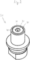
- Fig. 2 shows first clamping head 21 having first outer surface 31.
- the second clamping head 22 is substantially identical to the first clamping head 21 and has a second outer surface 32, the first and second outer surfaces facing towards one another. This amongst others implies that, in the shown example the first outer surface 31 and the second outer surface 32 are substantially mirror images from one another.
- Fig. 3 it is shown that the test sheet 2 has been interposed inbetween the first and second clamping heads 21, 22 in such manner that the first face 11 of the test sheet 2 is facing towards the first outer surface 31, while the second face 12 of the test sheet 2 is facing towards the second outer surface 32.
- Figs. 3 and 4 furthermore show part of a compressive movement mechanism arranged for selectively moving the first and the second clamping heads 21, 22 towards and away from one another, respectively, and arranged for imparting compressive forces to the first and the second clamping heads 21, 22 for clamping the test sheet 2 inbetween the first and the second clamping heads 21, 22.
- the compressive movement mechanism comprises slides 8, each being fixed relative to a concerning clamping head 21 or 22, as well as guides 7.
- the slides 8 are moveable to and fro along the guides 7 as indicated by double arrows 28.
- the compressive movement mechanism may of course have such slides 8 and guides 7 only for one of the first and the second clamping heads, the other one of the first and the second clamping heads not being moveable relative to a referential outside environment.
- Fig. 4 shows the clamped condition. In that condition, part of the first face 11 of the test sheet 2 is contacting the first outer surface 31 of the first clamping head 21, while part of the second face 12 of the test sheet 2 is contacting the second outer surface 32 of the second clamping head 22. From Figs. 3 and 4 it can also be seen that the first and second outer surfaces 31, 32 each have a non-flat shape in such manner that the first and second clamping heads 21, 22 in the clamped condition are transmitting the compressive forces to parts of the test sheet 2, which compressive forces create an imprinted sealing area 4 of the test sheet, which imprinted sealing area has a closed loop shape surrounding a desorption area 5 of the test sheet.
- test sheet in the clamped condition may be sandwiched inbetween a first cover sheet and a second cover sheet.
- first cover sheet may be in interposed position inbetween the sheet 2 and the first clamping head 21, while such second cover sheet may be in interposed position inbetween the sheet 2 and the second clamping head 22.
- the sheet 2 has been positioned relative to the clamping heads 21, 22 in such manner that the shown desorption area 5 contains at least part of the dried blood spot 3.
- the dried blood spot 3 has not been indicated in Figs. 3 and 4 .
- the dried blood spot 3 may partly appear more or less as a crust on one or both faces 11, 12 of the sheet 2.
- the desorption area 5 of the test sheet is contained in the space 6 enveloped by the first and the second outer surfaces 31, 32 and sealed by the imprinted sealing area 4.
- the first clamping head 21 comprises a first fluid conduit 41 extending therethrough and the second clamping head 22 comprises a second fluid conduit 42 extending therethrough.
- Each of the first and second fluid conduits 41, 42 are ending in said enveloped space 6 containing the desorption area 5 of the test sheet 2, for flushing the desorption area 5 of the clamped test sheet 2 with a sample elution fluid in such manner that the blood sample is desorbed and eluted from the desorption area 5, said flushing taking place via the first fluid conduit 41 and the second fluid conduit 42.
- the desorption area 5 of the sheet 2 will normally swell, and consequently acquire more sheet thickness.
- the desorption area 5 will nicely be embedded in the enveloped space 6, portions of the first and the second outer surfaces 31, 32 supporting the swollen desorption area 5.
- This supported embedding of the desorption area in the enveloped space 6 aids in preventing that, under relatively high fluid pressures occurring during the flushing, parts of the desorption area of the test sheet would be teared off from the test sheet.
- said swelling of the desorption area has not been shown in Fig. 4 .
- Fig. 5 shows the dried blood spot 3 after blood sample has been desorbed and eluted from the desorption area 5.
- the desorption area 5 not containing blood sample anymore, is shown in an unhatched manner.
- the remaining parts of the sheet that still contain blood from the dried blood spot 3, are indicated in hatched manner.
- the imprinted sealing area 4 has been indicated with a more dense hatching.
- the compressive movement mechanism 7, 8 is arranged for moving the first (21) and the second (22) clamping heads towards one another in such manner that in the clamped condition the shortest possible distance between the first (31) and the second (32) outer surfaces is less than 0.5 millimeter, preferably less than 0.2 millimeter, more preferably less than 0.05 millimeter.
- the non-flat shapes of the first 31 and second 32 outer surfaces are arranged such that the maximum diameter of the desorption area 5 is about 2.0 millimeter, while the maximum diameter of the imprinted sealing area 4 is about 4.5 millimeter.
- the shortest possible distance, measured along the imprinted sealing area 4 of the test sheet 2 when travelling from portions of the test sheet interior of said closed loop to portions of the test sheet exterior of said closed loop is about 1.25 millimeter. This satisfies the above mentioned criterion that said shortest possible distance preferably is at least 1.0 millimeter, thus giving a reliable sealing performance of the imprinted sealing area of the test sheet under relatively high fluid pressures occurring during the flushing.
- Fig. 5 shows the transition 29 between the imprinted sealing area 4 and the desorption area 5 of the test sheet 2.
- transition portions 9 (see Fig. 3 ) of the first 31 and second 32 outer surfaces, which transition portions 9 in the clamped condition are adjacent to and determine said transition 29, are rounded off.
- a rounding off with a radius of curvature of about 0.05 millimeter has turned out to be successful in preventing that, under relatively high fluid pressures occurring during the flushing, parts of the desorption area of the test sheet would be teared off from the test sheet.
- Fig. 6 shows apparatus 1 comprising the above described first and second clamping heads 21, 22.
- the apparatus 1 also comprises a compressive movement mechanism, such as the above described mechanism comprising the slides 8 and guides 7.
- the apparatus 1 further comprises analyzing means, in this example a liquid chromatography column 14, a gradient pump 15, a dispenser 16 and a six-port valve 51 of the stator/rotor type.
- Fig. 6 also shows a fluid conduit structure 25 for realizing fluid communication between the first and second fluid conduits 41, 42 of the clamping heads 21, 22, the valve 51, the column 14, the gradient pump 15 and the dispenser 16.
- the "black position" of the valve 51 refers to the valve position in which each of the shown three black-filled ring segments of the six-port valve serves as a fluid channel that provides fluid communication between the valve ports to which the concerning ring segment is connected. In the black position the three white-filled ring segments of the six-port valve do not provide such fluid communication between such ports.
- the "white position" of the valve 51 refers to the valve position in which each of the shown three white-filled ring segments of the six-port valve serves as a fluid channel that provides fluid communication between the valve ports to which the concerning ring segment is connected. In the white position the three black-filled ring segments of the six-port valve do not provide such fluid communication between such ports.
- the apparatus 1 of Fig. 6 further comprises an automatic test sheet handling system 17 comprising at least one magazine 18 for storing a plurality of test sheets, such as the test sheet 2, and a pick and place mechanism 19.
- the pick and place mechanism 19 is arranged at least for: picking up test sheets from the at least one test sheet magazine 18, interposing such test sheet 2 inbetween the clamping heads 21, 22, precise positioning of such interposed test sheet 2 relative to the clamping heads 21, 22; moving such test sheet 2 away from the clamping heads 21, 22; and storing or discarding such test sheet 2.
- test sheet in the clamped condition is sandwiched inbetween a first cover sheet and a second cover sheet.
- the automatic test sheet handling system 17 and/or the at least one magazine 18 and/or the pick and place mechanism 19 may additionally be arranged for handling and/or storing and/or pick and place such first and second cover sheets as well.
- each of the apparatus 101 and 201 may comprise such an automatic test sheet handling system 17.
- such systems 17 have not been shown in Figs. 7 and 8 .
- step (v) and (vi) can be performed in parallel with the liquid chromatography of step (iv).
- Fig. 7 shows apparatus 101. Similar to the apparatus 1 of Fig. 6 , the apparatus 101 of Fig. 7 comprises first and second clamping heads 21, 22, a compressive movement mechanism (not shown), a column 14, a gradient pump 15, a dispenser 16, a six-port valve 151, and a fluid conduit structure 25. Furthermore, the apparatus 101 comprises a sample loop 20 connected to the valve 151.
- the apparatus 101 of Fig. 7 it is possible to temporarily store at least the desorbed and eluted blood sample in the sample loop 20 and to inject at least part of the blood sample 3 stored in the sample loop 20, together with a mobile phase, into the column 14 for realizing said biomedical analysis, wherein said storing and said injecting is controlled by switching of the valve 151.
- the following successive steps that may be carried out with the apparatus 101 are provided as an elucidating example.
- liquid chromatography step (iv-a) can be performed in parallel with step (iv-b).
- the apparatus 201 of Fig. 8 comprises first and second clamping heads 21, 22, a compressive movement mechanism (not shown), a column 14, a gradient pump 15, a dispenser 16, a six-port valve 251, and a fluid conduit structure 25.
- the dispenser 16 has a first dispenser exit 16a and a second dispenser exit 16b.
- the apparatus 201 comprises a sample loop 220.
- the sample loop 220 is connected to the valve 251 and is furthermore integrated with an additional six-port valve 252 of the apparatus 201.
- the sample loop 220 comprises a disposable solid phase extraction cartridge 224 arranged between a corresponding clamping arrangement 61, 62 as known in the art.
- the dimensions, sizes and surface areas of the desorption area and the imprinted sealing area may vary.
- the non-flat shape of the at least one of the first and the second outer surfaces may be realized in various other ways.
- one of the first and the second outer surfaces could even be fully flat.
- the opposing portions of the first and the second outer surfaces which through compression directly create the imprinted sealing area do not necessarily need to be flat.
- these opposing portions may have mating undulations.
- a desorption area does not necessarily have to be in the center of a preprinted circular designation area on a test sheet. Off-center positions are also possible.
- pre-treat yet unused medical test sheets by creating one or more pre-imprinted sealing areas on them using clamping heads and a compressive movement mechanism.
- exactly known quantities of blood may be placed onto predefined desorption areas enclosed by pre-imprinted sealing areas, thus enabling accurate quantitative analyses.
- any reference signs placed between parentheses shall not be construed as limiting the claim.
- the word “comprising” does not exclude the presence of other features or steps than those listed in a claim.
- the words “a” and “an” shall not be construed as limited to “only one”, but instead are used to mean “at least one”, and do not exclude a plurality.
- the mere fact that certain measures are recited in mutually different claims does not indicate that a combination of these measures cannot be used to advantage.
Landscapes
- Health & Medical Sciences (AREA)
- Chemical & Material Sciences (AREA)
- Analytical Chemistry (AREA)
- General Health & Medical Sciences (AREA)
- Biochemistry (AREA)
- Physics & Mathematics (AREA)
- Life Sciences & Earth Sciences (AREA)
- General Physics & Mathematics (AREA)
- Immunology (AREA)
- Pathology (AREA)
- Clinical Laboratory Science (AREA)
- Chemical Kinetics & Catalysis (AREA)
- Hematology (AREA)
- Investigating Or Analysing Biological Materials (AREA)
- Sampling And Sample Adjustment (AREA)
Description
- The invention relates to a method and an apparatus for desorption of a blood sample from a medical test sheet comprising at least one dried blood spot thereon, for the purpose of biomedical analysis of the blood sample.
- Such a medical test sheet may for example comprise filter paper and/or other suitable material for containing the at least one dried blood sample thereon. A widely used such medical test sheet is for example the filter paper Whatman 903®, which filter paper has a thickness of about 0.5 millimeter. Five lined-up circles are preprinted on one face of such a Whatman 903® filter paper. These circles each have a diameter of about 12 millimeter. One or more drops of blood can be placed within these circles. After drying, the filter paper thus comprises at least one dried blood spot thereon.
- In order to analyse such a dried blood spot, at first, compounds need to be extracted from the filter paper. For that purpose, according to usual practice, a disc area corresponding to a preprinted circle on the filter paper containing dried blood sample, or of smaller diameter than that of the preprinted circle, is punched out of the filter paper.
- Traditionally, the punched-out disc is then placed into a little tray, bottle, other container, or the like. The extraction procedure is then carried out by an organic solvent or a mixture of water thereof, containing an internal standard (IS). Traditionally, after extraction and centrifugation, the supernatant is collected and analysed by liquid chromatography mass spectrometry.
- More recently, another concept has been described in the article Julien Deglon, Aurelien Thomas, Antonio Cataldo, Patrice Mangin, Christian Staub, "On-line desorption of dried blood spot: A novel approach for the direct LC/MS analysis of µ-whole blood samples", Journal of Pharmaceutical and Biomedical Analysis 49(2009) 1034-1039. Said article presents a new concept allowing the direct analysis of a dried blood spot coupled to a liquid chromatography mass spectrometry device (LC/MS). According to this new concept, a 10 millimeter disc containing dried blood sample is punched out of the filter paper sheet and an IS solution is added directly on the dried blood sample. Then, the blood disc is placed into a desorption cell, which is an inox cell that comprises two parts which can be brought in sealing engagement with each other via a separate sealing ring. The separate sealing ring has external-internal diameters of 14 and 12 millimeter, respectively, and thickness of 1.5 millimeter. The cell is then integrated into an LC/MS system where the analytes are desorbed out of the paper towards a column switching system ensuring the purification and separation of the compounds before their detection on a single quadrupole MS coupled to atmospheric pressure chemical ionisation (APCI) source. This new concept presented in said article is called "on-line" desorption of dried blood spots ("on-line DBS"), to indicate its distinction from the abovedescribed traditional "off-line" extraction, in which compounds need to be extracted from the filter paper disc prior to analysis.
-
GB1392304A -
WO00/54023A1 WO00/54023A1 - It is an object of the invention to provide a solution according to which on-line desorption of dried blood spots is faster and easier and allows for further automation of the process.
- For that purpose, the invention provides a method according to claim 1, as well as an apparatus according to
claim 7. Specific embodiments of the invention are set forth in the dependent claims. - Thus, the invention allows for interposal of the test sheet inbetween the clamping heads, which will then clamp onto the interposed test sheet. Then, the desorption area of the clamped test sheet may be flushed with the sample elution fluid in such manner that the blood sample is desorbed and eluted from the desorption area. So, there is no need for first punching-out a disc area of the test sheet containing dried blood sample. This is speeding up the procedure considerably. Furthermore, there is no need for making use of a separate sealing element, since the sealing is provided by part of the test sheet, i.e. in the form of the automatically generated imprinted sealing area of the test sheet.
- In a preferable embodiment of a method according to the invention, the test sheet in said clamped condition is sandwiched inbetween a first cover sheet and a second cover sheet. The first and second cover sheets may be clean sheets, not containing blood sample. Such use of such first and second cover sheets contributes to keeping the first and second clamping heads clean. These first and second cover sheets may be made of various materials, they may for example be made of or at least comprise filter paper.
- In another preferable embodiment, the method according to the invention further comprises the step of injecting the desorbed and eluted blood sample together with a mobile phase into analyzing means for realizing said biomedical analysis, wherein said sample elution fluid functions as said mobile phase and wherein said flushing of the desorption area and said injecting into the analyzing means are simultaneously driven by the action of a pumping means, such as a gradient pump or a high pressure dispenser. This allows for a simple configuration for performing the biomedical analysis of blood samples.
- In another preferable embodiment, the method according to the invention further comprises the steps of: temporarily storing at least the desorbed and eluted blood sample in a sample loop; and injecting at least part of the blood sample stored in the sample loop, together with a mobile phase, into analyzing means for realizing said biomedical analysis, wherein said storing and said injecting is controlled by switching of valve means. This allows for performing versatile and powerful biomedical analyses of blood samples. That is, characteristics of the sample elution fluid and the mobile phase, respectively, as well as their flow properties, respectively, may be optimized independently of one another.
- In a further preferable embodiment, the sample loop comprises a solid phase extraction cartridge. This allows for clean-up of the eluted blood sample by solid phase extraction. Thus, undesired compounds of the blood sample may be removed prior to analysis. Such additional cleaning-up of the blood sample removes detection interference.
- In a preferable embodiment of the apparatus according to the invention, the compressive movement mechanism is arranged for moving the first and the second clamping heads towards one another in such manner that in the clamped condition the shortest possible distance between the first and the second outer surfaces is less than 0.5 millimeter, preferably less than 0.2 millimeter, more preferably less than 0.05 millimeter.
- In another preferable embodiment of the apparatus according to the invention, the first outer surface and the second outer surface are substantially mirror images from one another. Since the first and second outer surfaces are facing towards one another, this allows for manufacturing the first and the second clamping heads as substantially identical to one another.
- Preferably, at least one of said first and said second outer surfaces has at least partly undergone an electrolytic polishing treatment. This not only impoves hygiene, but also improves the sealing performance of the imprinted sealing area of the test sheet.
- In another preferable embodiment, the non-flat shape of the at least one of the first and second outer surfaces is arranged such that the shortest possible distance, measured along the imprinted sealing area of the test sheet when travelling from portions of the test sheet interior of said closed loop to portions of the test sheet exterior of said closed loop, is at least 1.0 millimeter. In this way a reliable sealing performance of the imprinted sealing area of the test sheet is obtained under relatively high fluid pressures occurring during the flushing.
- In an apparatus according to the invention, transition portions of the at least one of the first and second outer surfaces, which transition portions in the clamped condition are adjacent to and determine the transition between the imprinted sealing area and the desorption area of the test sheet, are rounded off. This prevents that, under relatively high fluid pressures occurring during the flushing, parts of the desorption area of the test sheet would be teared off from the test sheet.
- Preferably, the apparatus further comprises: analyzing means for realizing said biomedical analysis; pumping means for realizing said flushing and injection of at least part of the desorbed and eluted blood sample together with a mobile phase into the analyzing means; and a fluid conduit structure for realizing fluid communication at least between the pumping means, the first and second fluid conduits, and the analyzing means.
- According to the invention, the apparatus further comprises an automatic test sheet handling system comprising at least one magazine for storing a plurality of such test sheets, and a pick and place mechanism for: at least picking up test sheets from the at least one test sheet magazine; interposing such test sheet inbetween the clamping heads; precise positioning of such interposed test sheet relative to the clamping heads; moving such test sheet away from the clamping heads; and storing or discarding such test sheet. Thus, a very high automation level of the process is achieved.
- Further details, aspects and embodiments of the invention will be described, by way of example only, with reference to the schematic figures in the enclosed drawing.
-
Fig. 1 shows, in upper view, an example of an embodiment of a medical test sheet, comprising a dried blood spot thereon, for use with a method according to the invention. -
Fig. 2 shows, in a perspective view, an example of an embodiment of a first clamping head for use with a method according to the invention. -
Fig. 3 shows, in a mid-longitudinal section, an example of an embodiment of first and second clamping heads, with the test sheet ofFig. 1 interposed therebetween, for use with a method according to the invention. -
Fig. 4 shows the example ofFig. 3 once again, however, with the first and second clamping heads in clamped condition. -
Fig. 5 shows, in upper view, a part of the example ofFig. 1 once again, however, in a condition in which blood sample of the dried blood spot on the test sheet has been desorbed and eluted from the test sheet using a method according to the invention. -
Fig. 6 shows an example of an embodiment of an apparatus for use in an example of an embodiment of a method according to the invention. -
Fig. 7 shows an example of another embodiment of an apparatus for use in an example of another embodiment of a method according to the invention. -
Fig. 8 shows an example of yet another embodiment of an apparatus for use in an example of yet another embodiment of a method according to the invention. - Note, that for the different embodiments shown in the different figures, sometimes the same reference numerals have been used to indicate parts or aspects which are similar for the different figures.
- The
medical test sheet 2 ofFig. 1 is made of filter paper and has a sheet thickness of about 0.5 millimeter. Although such type of test sheet is most commonly used in practice, other suitable materials for the test sheet and other sheet thicknesses (for example about 0.25, 0.75 or 1.0 millimeter or other thicknesses in this relatively small order of magnitude) are possible. - As shown in
Fig. 1 , one face of thetest sheet 2 is provided with a number ofpreprinted circles 10, indicating to users the areas on which drops of blood can be placed. InFig. 1 , within the interior of theleftmost circle 10, thetest sheet 2 comprises a driedblood spot 3 thereon.Test sheet 2 has a first face 11 and an opposingsecond face 12, seeFig. 3 . The driedblood spot 3 generally is extending throughout the whole thickness of thesheet 2, and will generally also appear more or less as a crust on one or both faces 11, 12 of thesheet 2. -
Fig. 2 shows first clampinghead 21 having firstouter surface 31. In the shown examples, thesecond clamping head 22 is substantially identical to thefirst clamping head 21 and has a secondouter surface 32, the first and second outer surfaces facing towards one another. This amongst others implies that, in the shown example the firstouter surface 31 and the secondouter surface 32 are substantially mirror images from one another. - In
Fig. 3 it is shown that thetest sheet 2 has been interposed inbetween the first and second clamping heads 21, 22 in such manner that the first face 11 of thetest sheet 2 is facing towards the firstouter surface 31, while thesecond face 12 of thetest sheet 2 is facing towards the secondouter surface 32. -
Figs. 3 and 4 furthermore show part of a compressive movement mechanism arranged for selectively moving the first and the second clamping heads 21, 22 towards and away from one another, respectively, and arranged for imparting compressive forces to the first and the second clamping heads 21, 22 for clamping thetest sheet 2 inbetween the first and the second clamping heads 21, 22. In the shown example, the compressive movement mechanism comprisesslides 8, each being fixed relative to a concerning clampinghead slides 8 are moveable to and fro along theguides 7 as indicated bydouble arrows 28. Instead of the shown configuration, the compressive movement mechanism may of course havesuch slides 8 and guides 7 only for one of the first and the second clamping heads, the other one of the first and the second clamping heads not being moveable relative to a referential outside environment. -
Fig. 4 shows the clamped condition. In that condition, part of the first face 11 of thetest sheet 2 is contacting the firstouter surface 31 of thefirst clamping head 21, while part of thesecond face 12 of thetest sheet 2 is contacting the secondouter surface 32 of thesecond clamping head 22. FromFigs. 3 and 4 it can also be seen that the first and secondouter surfaces test sheet 2, which compressive forces create an imprintedsealing area 4 of the test sheet, which imprinted sealing area has a closed loop shape surrounding adesorption area 5 of the test sheet. - It is remarked that, as mentioned above, the test sheet in the clamped condition may be sandwiched inbetween a first cover sheet and a second cover sheet. In
Figs. 3 and 4 , such embodiment with such first and second cover sheets has not been shown for reasons of simplicity. However, for such embodiment it will be clear that in the clamped condition ofFig. 4 , such first cover sheet may be in interposed position inbetween thesheet 2 and thefirst clamping head 21, while such second cover sheet may be in interposed position inbetween thesheet 2 and thesecond clamping head 22. - In
Fig. 4 it is assumed that thesheet 2 has been positioned relative to the clamping heads 21, 22 in such manner that the showndesorption area 5 contains at least part of the driedblood spot 3. For simplicity, the driedblood spot 3 has not been indicated inFigs. 3 and 4 . As mentioned above, the driedblood spot 3 may partly appear more or less as a crust on one or both faces 11, 12 of thesheet 2. InFig. 4 , thedesorption area 5 of the test sheet is contained in the space 6 enveloped by the first and the secondouter surfaces sealing area 4. - As shown in
Figs. 2-4 , thefirst clamping head 21 comprises a firstfluid conduit 41 extending therethrough and thesecond clamping head 22 comprises a secondfluid conduit 42 extending therethrough. Each of the first and secondfluid conduits desorption area 5 of thetest sheet 2, for flushing thedesorption area 5 of the clampedtest sheet 2 with a sample elution fluid in such manner that the blood sample is desorbed and eluted from thedesorption area 5, said flushing taking place via the firstfluid conduit 41 and the secondfluid conduit 42. During such flushing, thedesorption area 5 of thesheet 2 will normally swell, and consequently acquire more sheet thickness. Because of that swelling, thedesorption area 5 will nicely be embedded in the enveloped space 6, portions of the first and the secondouter surfaces swollen desorption area 5. This supported embedding of the desorption area in the enveloped space 6 aids in preventing that, under relatively high fluid pressures occurring during the flushing, parts of the desorption area of the test sheet would be teared off from the test sheet. For simplicity, said swelling of the desorption area has not been shown inFig. 4 . -
Fig. 5 shows the driedblood spot 3 after blood sample has been desorbed and eluted from thedesorption area 5. InFig. 5 thedesorption area 5, not containing blood sample anymore, is shown in an unhatched manner. The remaining parts of the sheet that still contain blood from the driedblood spot 3, are indicated in hatched manner. The imprintedsealing area 4 has been indicated with a more dense hatching. - In view of the above explained test sheet thicknesses having a relatively small order of magnitude, the
compressive movement mechanism - In the shown example, the non-flat shapes of the first 31 and second 32 outer surfaces are arranged such that the maximum diameter of the
desorption area 5 is about 2.0 millimeter, while the maximum diameter of the imprintedsealing area 4 is about 4.5 millimeter. Thus the shortest possible distance, measured along the imprintedsealing area 4 of thetest sheet 2 when travelling from portions of the test sheet interior of said closed loop to portions of the test sheet exterior of said closed loop, is about 1.25 millimeter. This satisfies the above mentioned criterion that said shortest possible distance preferably is at least 1.0 millimeter, thus giving a reliable sealing performance of the imprinted sealing area of the test sheet under relatively high fluid pressures occurring during the flushing. -
Fig. 5 shows the transition 29 between the imprintedsealing area 4 and thedesorption area 5 of thetest sheet 2. Preferably, transition portions 9 (seeFig. 3 ) of the first 31 and second 32 outer surfaces, which transition portions 9 in the clamped condition are adjacent to and determine said transition 29, are rounded off. In the shown example, a rounding off with a radius of curvature of about 0.05 millimeter has turned out to be successful in preventing that, under relatively high fluid pressures occurring during the flushing, parts of the desorption area of the test sheet would be teared off from the test sheet. - Reference is now made to
Fig. 6 , which shows apparatus 1 comprising the above described first and second clamping heads 21, 22. Although for simplicity not shown inFig. 6 , the apparatus 1 also comprises a compressive movement mechanism, such as the above described mechanism comprising theslides 8 and guides 7. The apparatus 1 further comprises analyzing means, in this example aliquid chromatography column 14, agradient pump 15, adispenser 16 and a six-port valve 51 of the stator/rotor type.Fig. 6 also shows afluid conduit structure 25 for realizing fluid communication between the first and secondfluid conduits valve 51, thecolumn 14, thegradient pump 15 and thedispenser 16. - It is remarked that the present document makes use of the following nomenclature for two different valve positions of the
valve 51. - The "black position" of the
valve 51 refers to the valve position in which each of the shown three black-filled ring segments of the six-port valve serves as a fluid channel that provides fluid communication between the valve ports to which the concerning ring segment is connected. In the black position the three white-filled ring segments of the six-port valve do not provide such fluid communication between such ports. - Analogously, the "white position" of the
valve 51 refers to the valve position in which each of the shown three white-filled ring segments of the six-port valve serves as a fluid channel that provides fluid communication between the valve ports to which the concerning ring segment is connected. In the white position the three black-filled ring segments of the six-port valve do not provide such fluid communication between such ports. - These terms "black position" and "white position" have been used with the same meanings for the similar six-
port valves Figs. 7 and8 . - The apparatus 1 of
Fig. 6 further comprises an automatic testsheet handling system 17 comprising at least onemagazine 18 for storing a plurality of test sheets, such as thetest sheet 2, and a pick andplace mechanism 19. The pick andplace mechanism 19 is arranged at least for: picking up test sheets from the at least onetest sheet magazine 18, interposingsuch test sheet 2 inbetween the clamping heads 21, 22, precise positioning of such interposedtest sheet 2 relative to the clamping heads 21, 22; movingsuch test sheet 2 away from the clamping heads 21, 22; and storing or discardingsuch test sheet 2. - It is remarked that, as mentioned above, embodiments are possible in which the test sheet in the clamped condition is sandwiched inbetween a first cover sheet and a second cover sheet. In such embodiments the automatic test
sheet handling system 17 and/or the at least onemagazine 18 and/or the pick andplace mechanism 19 may additionally be arranged for handling and/or storing and/or pick and place such first and second cover sheets as well. - It is furthermore remarked that also each of the
apparatus Figs. 7 and8 , may comprise such an automatic testsheet handling system 17. For simplicity,such systems 17 have not been shown inFigs. 7 and8 . - With the apparatus 1 of
Fig. 6 it is possible to inject the desorbed and eluted blood sample together with a mobile phase into thecolumn 14, wherein the sample elution fluid functions as said mobile phase and wherein the flushing of thedesorption area 5 and said injecting into thecolumn 14 are simultaneously driven by the action of thegradient pump 15. The following successive steps that may be carried out with the apparatus 1 are provided as an elucidating example. - (i) Initially, the
valve 51 is in its "black position" (explained above). - (ii) Position a
test sheet 2 inbetween the clamping heads 21, 22 and bring the clamping heads in clamping condition. - (iii)
Switch valve 51 from its black position into its white position. Mobile phase delivered by thegradient pump 15 is now flowing via the clamping heads 21, 22 through thedesorption area 5 of thesheet 2 towards thecolumn 14. - (iv) After some time, the
valve 51 is switched back into its black position. Mobile phase is now flowing directly from thegradient pump 15 towards thecolumn 14 in order to analyse the blood sample by liquid chromatography. - (v) Wash the clamping heads 21, 22 by means of the
dispenser 16 in order to remove possible remaining analyte and/or contaminants. - (vi) Move the clamping heads 21, 22 away from one another and remove the
sheet 2 away from the interspace between the clamping heads. - Note that the successive steps (v) and (vi) can be performed in parallel with the liquid chromatography of step (iv).
- Reference is now made to
Fig. 7 , which showsapparatus 101. Similar to the apparatus 1 ofFig. 6 , theapparatus 101 ofFig. 7 comprises first and second clamping heads 21, 22, a compressive movement mechanism (not shown), acolumn 14, agradient pump 15, adispenser 16, a six-port valve 151, and afluid conduit structure 25. Furthermore, theapparatus 101 comprises asample loop 20 connected to thevalve 151. - With the
apparatus 101 ofFig. 7 it is possible to temporarily store at least the desorbed and eluted blood sample in thesample loop 20 and to inject at least part of theblood sample 3 stored in thesample loop 20, together with a mobile phase, into thecolumn 14 for realizing said biomedical analysis, wherein said storing and said injecting is controlled by switching of thevalve 151. The following successive steps that may be carried out with theapparatus 101 are provided as an elucidating example. - (i) Initially, the
valve 151 is in its "black position" (explained above). - (ii) Position a
test sheet 2 inbetween the clamping heads 21, 22 and bring the clamping heads in clamping condition. - (iii) Desorb and elute blood sample from the
desorption area 5 of the clampedsheet 2 with a sample elution fluid delivered by thedispenser 16. The desorbed and eluted blood sample is now stored in thesample loop 20. - (iv-a)
Switch valve 151 from its black position into its white position. Mobile phase is now flowing through thesample loop 20 towards thecolumn 14 in order to analyse the blood sample, which was temporarily stored in thesample loop 20, by liquid chromatography. - (iv-b) In the meanwhile wash the clamping heads 21, 22 by means of the
dispenser 16 in order to remove possible remaining analyte and/or contaminants. - (v) After some time, the
valve 151 is switched back into its black position. - (vi) Move the clamping heads 21, 22 away from one another and remove the
sheet 2 away from the interspace between the clamping heads. - Note that the liquid chromatography step (iv-a) can be performed in parallel with step (iv-b).
- Reference is now made to
Fig. 8 , which showsapparatus 201. Similar to the apparatus 1 ofFig. 6 , theapparatus 201 ofFig. 8 comprises first and second clamping heads 21, 22, a compressive movement mechanism (not shown), acolumn 14, agradient pump 15, adispenser 16, a six-port valve 251, and afluid conduit structure 25. In the present embodiment thedispenser 16 has a first dispenser exit 16a and asecond dispenser exit 16b. Furthermore, theapparatus 201 comprises asample loop 220. Thesample loop 220 is connected to thevalve 251 and is furthermore integrated with an additional six-port valve 252 of theapparatus 201. In addition, thesample loop 220 comprises a disposable solidphase extraction cartridge 224 arranged between acorresponding clamping arrangement - With the
apparatus 201 ofFig. 8 it is possible to remove undesired compounds of the blood sample prior to analysis. - The following successive steps that may be carried out with the
apparatus 201 are provided as an elucidating example. - (i) Initially, each of the
valves - (ii-a) Position a
test sheet 2 inbetween the clamping heads 21, 22 and bring the clamping heads in clamping condition. - (ii-b) Place and clamp a solid
phase extraction cartridge 224 between the clampingarrangement - (iii) Condition the
cartridge 224 with fluids delivered by thedispenser 16 via its first dispenser exit 16a. - (iv)
Switch valve 251 from its black position into its white position. - (v) Desorb and elute blood sample from the
desorption area 5 of the clampedsheet 2, with a sample elution fluid delivered by thedispenser 16 via its first dispenser exit 16a, towards thecartridge 224. - (vi)
Switch valve 251 from its white position into its black position. - (vii) Wash the
cartridge 224 with a washing fluid delivered by thedispenser 16 via its first dispenser exit 16a, thus removing undesired compounds of the blood sample prior to analysis. - (viii) Switch the
additional valve 252 from its black position into its white position. Under the action of thegradient pump 15, mobile phase is now flowing through thecartridge 224 towards thecolumn 14 in order to analyse the blood sample by liquid chromatography. - (ix) In the meanwhile wash the clamping heads 21, 22 by means of the
dispenser 16 via itssecond dispenser exit 16b in order to remove possible remaining analyte and/or contaminants, move the clamping heads 21, 22 away from one another and remove thesheet 2 away from the interspace between the clamping heads. - (x) After some time, switch the
additional valve 252 from its white position into its black position. - Note that the successive steps (ii-b) and (iii) can be performed in parallel with step (ii-a).
- In the foregoing specification, the invention has been described with reference to specific examples of embodiments of the invention. However, various modifications and changes may be made therein without departing from the broader scope of the invention as set forth in the appended claims.
- It is for example possible to arrange the invention such that, instead of the shown circularly ring shaped imprinted sealing area, various other closed loop shapes are obtained, such as polygonal, oval, etcetera. Consequently, also various other shapes of the desorption area are possible.
- Also, the dimensions, sizes and surface areas of the desorption area and the imprinted sealing area may vary.
- Furthermore, it is possible to simultaneously create more than one imprinted sealing area and desorption area for a test sheet.
- Also, the non-flat shape of the at least one of the first and the second outer surfaces may be realized in various other ways. For example, one of the first and the second outer surfaces could even be fully flat.
- Furthermore, the opposing portions of the first and the second outer surfaces which through compression directly create the imprinted sealing area do not necessarily need to be flat. For example, these opposing portions may have mating undulations.
- Also, a desorption area does not necessarily have to be in the center of a preprinted circular designation area on a test sheet. Off-center positions are also possible.
- Furthermore it is possible to make arrangements for adding a low strength solvent (e.g. water) to the desorbed and eluted blood sample prior to its analysis. This allows the use of a sample elution fluid having high strength without compromising the analysis, such as (High Performance/High Pressure) liquid chromatography (HP)LC separation.
- Also, arrangements may be made for using pre-heated sample elution fluid in order to enhance solubility of analytes without increasing the strength of the sample elution fluid. This helps to avoid disturbing the analysis, such as (HP)LC separation, with incompatible solvents.
- Furthermore it is possible to pre-treat yet unused medical test sheets by creating one or more pre-imprinted sealing areas on them using clamping heads and a compressive movement mechanism. In that way, exactly known quantities of blood may be placed onto predefined desorption areas enclosed by pre-imprinted sealing areas, thus enabling accurate quantitative analyses.
- However, other modifications, variations and alternatives are also possible. The specifications and drawings are, accordingly, to be regarded in an illustrative rather than in a restrictive sense.
- In the claims, any reference signs placed between parentheses shall not be construed as limiting the claim. The word "comprising" does not exclude the presence of other features or steps than those listed in a claim. Furthermore, the words "a" and "an" shall not be construed as limited to "only one", but instead are used to mean "at least one", and do not exclude a plurality. The mere fact that certain measures are recited in mutually different claims does not indicate that a combination of these measures cannot be used to advantage.
Claims (12)
- Method for desorption of a blood sample from a medical test sheet (2) comprising at least one dried blood spot (3) thereon, for the purpose of biomedical analysis of the blood sample, comprising the steps of:- interposing the test sheet, having first (11) and second (12) opposite faces, inbetween first (21) and second (22) clamping heads, the first clamping head having a first outer surface (31) and the second clamping head having a second outer surface (32), the first and second outer surfaces facing towards one another, in such manner that the first face (11) of the test sheet is facing towards the first outer surface (31), while the second face (12) of the test sheet is facing towards the second outer surface (32);- clamping the first and the second clamping heads in such manner that the first and the second clamping heads in clamped condition are defining a desorption area (5) of the test sheet, which desorption area contains at least part of the at least one dried blood spot (3) and which desorption area of the test sheet is contained in a space (6) enveloped by the first (31) and the second (32) outer surfaces; and- flushing the desorption area (5) of the clamped test sheet (2) with a sample elution fluid in such manner that the blood sample is desorbed and eluted from the desorption area, said flushing taking place via a first fluid conduit (41) extending through the first clamping head and a second fluid conduit (42) extending through the second clamping head, each of the first and second fluid conduits ending in said enveloped space (6) containing the desorption area (5) of the test sheet;characterized in that
said clamping of the first and the second clamping heads is onto the thus interposed test sheet (2) and at least one of the first (31) and second (32) outer surfaces has a non-flat shape in such manner that in said clamped condition:- the first and the second clamping are transmitting compressive forces to parts of the test sheet, which compressive forces create an imprinted sealing area (4) of the test sheet, which imprinted sealing area has a closed loop shape surrounding said desorption area (5) of the test sheet; and- said enveloped space (6) is sealed by the imprinted sealing area;wherein the method is performed using an automatic test sheet handling system (17) comprising at least one magazine (18) for storing a plurality of such test sheets (2), and a pick and place mechanism (19), which:- prior to the step of said interposing, picks up the test sheet from the at least one magazine;- in-between the step of said interposing and the step of said clamping, precisely positions the test sheet relative to the clamping heads;- after the step of said flushing, moves the test sheet away from the clamping heads, and stores or discards the test sheet. - Method according to claim 1, wherein the test sheet (2) comprises filter paper, which filter paper contains at least part of the at least one dried blood spot (3).
- Method according to claim 1 or 2, wherein the test sheet (2) in said clamped condition is sandwiched inbetween a first cover sheet and a second cover sheet.
- Method according to any one of claims 1-3, further comprising the step of:- injecting the desorbed and eluted blood sample together with a mobile phase into analyzing means (14) for realizing said biomedical analysis, wherein said sample elution fluid functions as said mobile phase and wherein said flushing of the desorption area (5) and said injecting into the analyzing means are simultaneously driven by the action of a pumping means (15), such as a gradient pump (15) or a high pressure dispenser.
- Method according to any one of claims 1-3, further comprising the steps of:- temporarily storing at least the desorbed and eluted blood sample in a sample loop (20; 220); and- injecting at least part of the blood sample (3) stored in the sample loop, together with a mobile phase, into analyzing means (14) for realizing said biomedical analysis, wherein said storing and said injecting is controlled by switching of valve means (151; 251, 252).
- Method according to claim 5, wherein the sample loop (220) comprises a solid phase extraction cartridge (224).
- Apparatus (1; 101; 201) for desorption of a blood sample from a medical test sheet (2) comprising at least one dried blood spot (3) thereon, for the purpose of biomedical analysis of the blood sample, comprising:- a first clamping head (21) with a first outer surface (31) and a second clamping head (22) with a second outer surface (32), the first and second outer surfaces facing towards one another;- a compressive movement mechanism (7, 8) arranged for selectively moving (28) the first and the second clamping heads towards and away from one another, respectively, and arranged for imparting compressive forces to the first and the second clamping heads when the test sheet, having first (11) and second (12) opposite faces, is interposed inbetween the first (21) and second (22) clamping heads in such manner that the first face (11) of the test sheet is facing towards the first outer surface (31), while the second face (12) of the test sheet is facing towards the second outer surface (32);wherein the first and second clamping heads in clamped condition are defining a desorption area (5) of the test sheet, which desorption area contains at least part of the at least one dried blood spot (3) and which desorption area of the test sheet is contained in a space (6) enveloped by the first and the second outer surfaces;
and wherein the first clamping head (21) comprises a first fluid conduit (41) extending therethrough and the second clamping head (22) comprises a second fluid conduit (42) extending therethrough, each of the first and second fluid conduits ending in said enveloped space (6) containing the desorption area (5) of the test sheet, for flushing the desorption area of the clamped test sheet with a sample elution fluid in such manner that the blood sample is desorbed and eluted from the desorption area, said flushing taking place via said first fluid conduit and said second fluid conduit
characterized in that- at least one of the first (31) and second (32) outer surfaces has a non-flat shape in such manner that the first and second clamping heads in the clamped condition are transmitting the compressive forces to parts of the test sheet, which compressive forces create an imprinted sealing area (4) of the test sheet, which imprinted sealing area has a closed loop shape surrounding said desorption area (5) of the test sheet, and in such manner that said enveloped space (6) is sealed by the imprinted sealing area;- transition portions (9) of the at least one of the first (31) and second (32) outer surfaces, which transition portions (9) in the clamped condition are adjacent to and determine the transition (29) between the imprinted sealing area (4) and the desorption area (5) of the test sheet, are rounded off; and- the apparatus further comprises an automatic test sheet handling system (17) comprising at least one magazine (18) for storing a plurality of such test sheets (2), and a pick and place mechanism (19) for at least: picking up test sheets from the at least one test sheet magazine; interposing such test sheet inbetween the clamping heads; precise positioning of such interposed test sheet relative to the clamping heads; moving such test sheet away from the clamping heads; and storing or discarding such test sheet. - Apparatus according to claim 7, wherein the compressive movement mechanism (7, 8) is arranged for moving the first (21) and the second (22) clamping heads towards one another in such manner that in the clamped condition the shortest possible distance between the first (31) and the second (32) outer surfaces is less than 0.5 millimeter, preferably less than 0.2 millimeter, more preferably less than 0.05 millimeter.
- Apparatus according to claim 7 or 8, wherein the first outer surface (31) and the second outer surface (32) are substantially mirror images from one another.
- Apparatus according to any one of claims 7-9, wherein at least one of said first (31) and said second (32) outer surfaces has at least partly undergone an electrolytic polishing treatment.
- Apparatus according to any one of claims 7-10, wherein said non-flat shape of the at least one of the first (31) and second (32) outer surfaces is arranged such that the shortest possible distance, measured along the imprinted sealing area (4) of the test sheet (2) when travelling from portions of the test sheet interior of said closed loop to portions of the test sheet exterior of said closed loop, is at least 1.0 millimeter.
- Apparatus according to any one of claims 7-11, further comprising:- analyzing means (14) for realizing said biomedical analysis;- pumping means (15, 16) for realizing said flushing and injection of at least part of the desorbed and eluted blood sample together with a mobile phase into the analyzing means (14); and- a fluid conduit structure (25) for realizing fluid communication at least between the pumping means (15, 16), the first (41) and second (42) fluid conduits, and the analyzing means (14).
Priority Applications (3)
| Application Number | Priority Date | Filing Date | Title |
|---|---|---|---|
| EP09177613.8A EP2330402B1 (en) | 2009-12-01 | 2009-12-01 | Method and apparatus for desorption of a blood sample from a medical test sheet |
| US12/899,001 US8586382B2 (en) | 2009-12-01 | 2010-10-06 | Method and apparatus for desorption of a blood sample from a medical test sheet |
| US14/050,951 US9207151B2 (en) | 2009-12-01 | 2013-10-10 | Method and apparatus for desorption of a blood sample from a medical test sheet |
Applications Claiming Priority (1)
| Application Number | Priority Date | Filing Date | Title |
|---|---|---|---|
| EP09177613.8A EP2330402B1 (en) | 2009-12-01 | 2009-12-01 | Method and apparatus for desorption of a blood sample from a medical test sheet |
Publications (2)
| Publication Number | Publication Date |
|---|---|
| EP2330402A1 EP2330402A1 (en) | 2011-06-08 |
| EP2330402B1 true EP2330402B1 (en) | 2017-02-15 |
Family
ID=41667362
Family Applications (1)
| Application Number | Title | Priority Date | Filing Date |
|---|---|---|---|
| EP09177613.8A Active EP2330402B1 (en) | 2009-12-01 | 2009-12-01 | Method and apparatus for desorption of a blood sample from a medical test sheet |
Country Status (2)
| Country | Link |
|---|---|
| US (2) | US8586382B2 (en) |
| EP (1) | EP2330402B1 (en) |
Families Citing this family (18)
| Publication number | Priority date | Publication date | Assignee | Title |
|---|---|---|---|---|
| US8685749B2 (en) * | 2009-12-02 | 2014-04-01 | Whatman International Limited | Methods and systems for processing samples on porous substrates |
| CH703256A1 (en) * | 2010-06-04 | 2011-12-15 | Werner Doebelin | Method and apparatus for automatic and direct analysis of dried blood spots samples by LC-MS system. |
| US9546935B1 (en) | 2010-08-25 | 2017-01-17 | Thomas W. Astle | Dried specimen storage slides, systems and methods |
| US9150983B1 (en) * | 2012-05-02 | 2015-10-06 | Thomas W. Astle | Automated dried blood spot system and method |
| WO2012035117A1 (en) | 2010-09-15 | 2012-03-22 | Basf Plant Science Company Gmbh | Extraction device and method for extracting ingredients from a biological sample |
| WO2013101262A1 (en) * | 2011-02-28 | 2013-07-04 | Waters Technologies Corporation | Spectroscopic sample inspection for automated chromatography |
| JP6203721B2 (en) * | 2011-08-22 | 2017-09-27 | ウオーターズ・テクノロジーズ・コーポレイシヨン | Analysis of dried blood spot samples in a microfluidic system with extraction sample dilution |
| US9482603B2 (en) * | 2011-09-23 | 2016-11-01 | Waters Technologies Corporation | Solid phase extraction device for dried sample cards |
| US20130090253A1 (en) | 2011-09-23 | 2013-04-11 | Nanoink, Inc. | Accurate quantitation of biomarkers in samples |
| CN103217518B (en) * | 2013-03-19 | 2014-04-02 | 广州市丰华生物工程有限公司 | Application of blood slice stent in invitro diagnostic reagent |
| GB201318814D0 (en) * | 2013-10-24 | 2013-12-11 | Petroleum & Chemical Corp | Microfluidic devices and arrangements for supplying such devices with reagents and biological samples |
| US20150167052A1 (en) * | 2013-12-13 | 2015-06-18 | General Electric Company | Sample storage and extraction device for flow through elution of analytes |
| EP4220180A3 (en) * | 2014-07-29 | 2023-08-16 | Joachim Gerstel | Arrangement for preparing a plurality of samples for an analytical method |
| EP3204770A1 (en) | 2014-10-07 | 2017-08-16 | 3M Innovative Properties Company | Method of detecting an analyte using chromatographic enrichment |
| BR112017006326A2 (en) * | 2014-10-07 | 2017-12-19 | 3M Innovative Properties Co | method for detecting a target microorganism, device and kit |
| DE102015007642A1 (en) | 2015-06-17 | 2016-12-22 | Sarstedt Ag & Co. | Method and device for providing a dried amount of liquid, in particular having blood, absorbent sample carriers |
| WO2017060271A1 (en) | 2015-10-05 | 2017-04-13 | Universiteit Gent | Dried blood sample analysis |
| PL3478412T3 (en) * | 2016-06-30 | 2020-10-19 | Sarstedt Ag & Co. Kg | Device for making available absorbent sample carriers having a quantity of dried liquid, in particular blood |
Family Cites Families (8)
| Publication number | Priority date | Publication date | Assignee | Title |
|---|---|---|---|---|
| BE786213A (en) * | 1971-07-13 | 1973-01-15 | Technicon Instr | METHOD AND APPARATUS FOR THE ANALYSIS OF SAMPLES, IN PARTICULAR DESANG |
| US4224031A (en) * | 1977-11-15 | 1980-09-23 | Mee John M L | CI Mass spectrometric analysis of physiologically active compounds |
| US6258605B1 (en) * | 1999-03-26 | 2001-07-10 | Neo Gen Screening, Inc. | Clinical method for the genetic screening of newborns using tandem mass spectrometry |
| ES2290014T3 (en) * | 1999-03-05 | 2008-02-16 | Spark Holland B.V. | SOLID PHASE EXTRACTION INSTRUMENT AND METHOD FOR SOLID PHASE EXTRACTION. |
| DE10036293C2 (en) | 2000-07-26 | 2002-08-14 | Heinrich Luftmann | Device for preparing the qualitative and quantitative analysis of substance stains on a thin layer plate |
| US20100197510A1 (en) * | 2007-03-08 | 2010-08-05 | Michael Spain | Methods for rapid disease screening |
| CH701526B1 (en) | 2009-07-24 | 2013-02-15 | Camag | Method and apparatus for preparation of substances for qualitative and quantitative analyzes. |
| US8685749B2 (en) | 2009-12-02 | 2014-04-01 | Whatman International Limited | Methods and systems for processing samples on porous substrates |
-
2009
- 2009-12-01 EP EP09177613.8A patent/EP2330402B1/en active Active
-
2010
- 2010-10-06 US US12/899,001 patent/US8586382B2/en active Active
-
2013
- 2013-10-10 US US14/050,951 patent/US9207151B2/en active Active
Non-Patent Citations (1)
| Title |
|---|
| None * |
Also Published As
| Publication number | Publication date |
|---|---|
| EP2330402A1 (en) | 2011-06-08 |
| US8586382B2 (en) | 2013-11-19 |
| US20110129940A1 (en) | 2011-06-02 |
| US20140037501A1 (en) | 2014-02-06 |
| US9207151B2 (en) | 2015-12-08 |
Similar Documents
| Publication | Publication Date | Title |
|---|---|---|
| EP2330402B1 (en) | Method and apparatus for desorption of a blood sample from a medical test sheet | |
| US7374724B2 (en) | Device for processing samples, use of the device, and method for producing the device | |
| US8410426B2 (en) | Devices and methods for coupling mass spectrometry devices with chromatography systems | |
| Gilar et al. | Advances in sample preparation in electromigration, chromatographic and mass spectrometric separation methods | |
| JP5123847B2 (en) | Fluid engineering equipment | |
| US8048386B2 (en) | Fluid processing and control | |
| US20240082838A1 (en) | Nucleic acid extraction and purification cartridges | |
| US8784630B2 (en) | Sample stacking method using on-line automatic solid phase extraction coupled to nonaqueous capillary electrophoresis and interface structure between solid-phase preconcentration cartridge and capillary therefor | |
| WO2013028765A1 (en) | Microfluidic device with dried blood spots (dbs) card interface | |
| EP1804972B1 (en) | Multiple cartridge, cartridge array frame | |
| WO2001019520A1 (en) | High density cast-in-place sample preparation card | |
| JP2003112002A (en) | Sample processing apparatus, its use and its manufacturing method | |
| EP1151793B1 (en) | Processing proteins from gels for analysis using mass spectrometry | |
| CN114574349B (en) | Equipment for adapting to card box | |
| JP2004529348A (en) | Separation unit, separation method, and device for attaching separation unit to separation apparatus | |
| US20210199624A1 (en) | Micro solid phase extraction devices and methods | |
| US20190250130A1 (en) | System for subjecting a sample to chromatographic analysis | |
| US20230366861A1 (en) | Packing material-containing microcolumn | |
| EP2174714B1 (en) | Apparatus with a composite structure for sample preparation | |
| CN117110484A (en) | Sample injection probe device based on membrane auxiliary strategy and analysis method | |
| JP2006276009A (en) | Protein fractionation device, and protein fractionation/recovery method using the same |
Legal Events
| Date | Code | Title | Description |
|---|---|---|---|
| PUAI | Public reference made under article 153(3) epc to a published international application that has entered the european phase |
Free format text: ORIGINAL CODE: 0009012 |
|
| AK | Designated contracting states |
Kind code of ref document: A1 Designated state(s): AT BE BG CH CY CZ DE DK EE ES FI FR GB GR HR HU IE IS IT LI LT LU LV MC MK MT NL NO PL PT RO SE SI SK SM TR |
|
| AX | Request for extension of the european patent |
Extension state: AL BA RS |
|
| 17P | Request for examination filed |
Effective date: 20111020 |
|
| 17Q | First examination report despatched |
Effective date: 20111108 |
|
| TPAC | Observations filed by third parties |
Free format text: ORIGINAL CODE: EPIDOSNTIPA |
|
| GRAP | Despatch of communication of intention to grant a patent |
Free format text: ORIGINAL CODE: EPIDOSNIGR1 |
|
| INTG | Intention to grant announced |
Effective date: 20161017 |
|
| GRAS | Grant fee paid |
Free format text: ORIGINAL CODE: EPIDOSNIGR3 |
|
| GRAA | (expected) grant |
Free format text: ORIGINAL CODE: 0009210 |
|
| AK | Designated contracting states |
Kind code of ref document: B1 Designated state(s): AT BE BG CH CY CZ DE DK EE ES FI FR GB GR HR HU IE IS IT LI LT LU LV MC MK MT NL NO PL PT RO SE SI SK SM TR |
|
| REG | Reference to a national code |
Ref country code: CH Ref legal event code: EP Ref country code: GB Ref legal event code: FG4D |
|
| REG | Reference to a national code |
Ref country code: IE Ref legal event code: FG4D |
|
| REG | Reference to a national code |
Ref country code: AT Ref legal event code: REF Ref document number: 868181 Country of ref document: AT Kind code of ref document: T Effective date: 20170315 |
|
| REG | Reference to a national code |
Ref country code: DE Ref legal event code: R096 Ref document number: 602009044174 Country of ref document: DE |
|
| REG | Reference to a national code |
Ref country code: NL Ref legal event code: MP Effective date: 20170215 |
|
| REG | Reference to a national code |
Ref country code: LT Ref legal event code: MG4D |
|
| REG | Reference to a national code |
Ref country code: AT Ref legal event code: MK05 Ref document number: 868181 Country of ref document: AT Kind code of ref document: T Effective date: 20170215 |
|
| PG25 | Lapsed in a contracting state [announced via postgrant information from national office to epo] |
Ref country code: LT Free format text: LAPSE BECAUSE OF FAILURE TO SUBMIT A TRANSLATION OF THE DESCRIPTION OR TO PAY THE FEE WITHIN THE PRESCRIBED TIME-LIMIT Effective date: 20170215 Ref country code: GR Free format text: LAPSE BECAUSE OF FAILURE TO SUBMIT A TRANSLATION OF THE DESCRIPTION OR TO PAY THE FEE WITHIN THE PRESCRIBED TIME-LIMIT Effective date: 20170516 Ref country code: NO Free format text: LAPSE BECAUSE OF FAILURE TO SUBMIT A TRANSLATION OF THE DESCRIPTION OR TO PAY THE FEE WITHIN THE PRESCRIBED TIME-LIMIT Effective date: 20170515 Ref country code: FI Free format text: LAPSE BECAUSE OF FAILURE TO SUBMIT A TRANSLATION OF THE DESCRIPTION OR TO PAY THE FEE WITHIN THE PRESCRIBED TIME-LIMIT Effective date: 20170215 Ref country code: HR Free format text: LAPSE BECAUSE OF FAILURE TO SUBMIT A TRANSLATION OF THE DESCRIPTION OR TO PAY THE FEE WITHIN THE PRESCRIBED TIME-LIMIT Effective date: 20170215 |
|
| PG25 | Lapsed in a contracting state [announced via postgrant information from national office to epo] |
Ref country code: SE Free format text: LAPSE BECAUSE OF FAILURE TO SUBMIT A TRANSLATION OF THE DESCRIPTION OR TO PAY THE FEE WITHIN THE PRESCRIBED TIME-LIMIT Effective date: 20170215 Ref country code: PT Free format text: LAPSE BECAUSE OF FAILURE TO SUBMIT A TRANSLATION OF THE DESCRIPTION OR TO PAY THE FEE WITHIN THE PRESCRIBED TIME-LIMIT Effective date: 20170615 Ref country code: NL Free format text: LAPSE BECAUSE OF FAILURE TO SUBMIT A TRANSLATION OF THE DESCRIPTION OR TO PAY THE FEE WITHIN THE PRESCRIBED TIME-LIMIT Effective date: 20170215 Ref country code: LV Free format text: LAPSE BECAUSE OF FAILURE TO SUBMIT A TRANSLATION OF THE DESCRIPTION OR TO PAY THE FEE WITHIN THE PRESCRIBED TIME-LIMIT Effective date: 20170215 Ref country code: ES Free format text: LAPSE BECAUSE OF FAILURE TO SUBMIT A TRANSLATION OF THE DESCRIPTION OR TO PAY THE FEE WITHIN THE PRESCRIBED TIME-LIMIT Effective date: 20170215 Ref country code: AT Free format text: LAPSE BECAUSE OF FAILURE TO SUBMIT A TRANSLATION OF THE DESCRIPTION OR TO PAY THE FEE WITHIN THE PRESCRIBED TIME-LIMIT Effective date: 20170215 Ref country code: BG Free format text: LAPSE BECAUSE OF FAILURE TO SUBMIT A TRANSLATION OF THE DESCRIPTION OR TO PAY THE FEE WITHIN THE PRESCRIBED TIME-LIMIT Effective date: 20170515 |
|
| PG25 | Lapsed in a contracting state [announced via postgrant information from national office to epo] |
Ref country code: EE Free format text: LAPSE BECAUSE OF FAILURE TO SUBMIT A TRANSLATION OF THE DESCRIPTION OR TO PAY THE FEE WITHIN THE PRESCRIBED TIME-LIMIT Effective date: 20170215 Ref country code: SK Free format text: LAPSE BECAUSE OF FAILURE TO SUBMIT A TRANSLATION OF THE DESCRIPTION OR TO PAY THE FEE WITHIN THE PRESCRIBED TIME-LIMIT Effective date: 20170215 Ref country code: IT Free format text: LAPSE BECAUSE OF FAILURE TO SUBMIT A TRANSLATION OF THE DESCRIPTION OR TO PAY THE FEE WITHIN THE PRESCRIBED TIME-LIMIT Effective date: 20170215 Ref country code: CZ Free format text: LAPSE BECAUSE OF FAILURE TO SUBMIT A TRANSLATION OF THE DESCRIPTION OR TO PAY THE FEE WITHIN THE PRESCRIBED TIME-LIMIT Effective date: 20170215 Ref country code: RO Free format text: LAPSE BECAUSE OF FAILURE TO SUBMIT A TRANSLATION OF THE DESCRIPTION OR TO PAY THE FEE WITHIN THE PRESCRIBED TIME-LIMIT Effective date: 20170215 |
|
| REG | Reference to a national code |
Ref country code: DE Ref legal event code: R097 Ref document number: 602009044174 Country of ref document: DE |
|
| PG25 | Lapsed in a contracting state [announced via postgrant information from national office to epo] |
Ref country code: PL Free format text: LAPSE BECAUSE OF FAILURE TO SUBMIT A TRANSLATION OF THE DESCRIPTION OR TO PAY THE FEE WITHIN THE PRESCRIBED TIME-LIMIT Effective date: 20170215 Ref country code: DK Free format text: LAPSE BECAUSE OF FAILURE TO SUBMIT A TRANSLATION OF THE DESCRIPTION OR TO PAY THE FEE WITHIN THE PRESCRIBED TIME-LIMIT Effective date: 20170215 Ref country code: SM Free format text: LAPSE BECAUSE OF FAILURE TO SUBMIT A TRANSLATION OF THE DESCRIPTION OR TO PAY THE FEE WITHIN THE PRESCRIBED TIME-LIMIT Effective date: 20170215 |
|
| REG | Reference to a national code |
Ref country code: FR Ref legal event code: PLFP Year of fee payment: 9 |
|
| PLBE | No opposition filed within time limit |
Free format text: ORIGINAL CODE: 0009261 |
|
| STAA | Information on the status of an ep patent application or granted ep patent |
Free format text: STATUS: NO OPPOSITION FILED WITHIN TIME LIMIT |
|
| 26N | No opposition filed |
Effective date: 20171116 |
|
| PG25 | Lapsed in a contracting state [announced via postgrant information from national office to epo] |
Ref country code: SI Free format text: LAPSE BECAUSE OF FAILURE TO SUBMIT A TRANSLATION OF THE DESCRIPTION OR TO PAY THE FEE WITHIN THE PRESCRIBED TIME-LIMIT Effective date: 20170215 |
|
| REG | Reference to a national code |
Ref country code: IE Ref legal event code: MM4A |
|
| PG25 | Lapsed in a contracting state [announced via postgrant information from national office to epo] |
Ref country code: LU Free format text: LAPSE BECAUSE OF NON-PAYMENT OF DUE FEES Effective date: 20171201 Ref country code: MT Free format text: LAPSE BECAUSE OF NON-PAYMENT OF DUE FEES Effective date: 20171201 |
|
| REG | Reference to a national code |
Ref country code: BE Ref legal event code: MM Effective date: 20171231 |
|
| PG25 | Lapsed in a contracting state [announced via postgrant information from national office to epo] |
Ref country code: IE Free format text: LAPSE BECAUSE OF NON-PAYMENT OF DUE FEES Effective date: 20171201 |
|
| PG25 | Lapsed in a contracting state [announced via postgrant information from national office to epo] |
Ref country code: BE Free format text: LAPSE BECAUSE OF NON-PAYMENT OF DUE FEES Effective date: 20171231 |
|
| PG25 | Lapsed in a contracting state [announced via postgrant information from national office to epo] |
Ref country code: HU Free format text: LAPSE BECAUSE OF FAILURE TO SUBMIT A TRANSLATION OF THE DESCRIPTION OR TO PAY THE FEE WITHIN THE PRESCRIBED TIME-LIMIT; INVALID AB INITIO Effective date: 20091201 Ref country code: MC Free format text: LAPSE BECAUSE OF FAILURE TO SUBMIT A TRANSLATION OF THE DESCRIPTION OR TO PAY THE FEE WITHIN THE PRESCRIBED TIME-LIMIT Effective date: 20170215 |
|
| REG | Reference to a national code |
Ref country code: CH Ref legal event code: PCOW Free format text: NEW ADDRESS: WAANDERWEG 40, 7812 HZ EMMEN (NL) |
|
| PG25 | Lapsed in a contracting state [announced via postgrant information from national office to epo] |
Ref country code: CY Free format text: LAPSE BECAUSE OF NON-PAYMENT OF DUE FEES Effective date: 20170215 |
|
| PG25 | Lapsed in a contracting state [announced via postgrant information from national office to epo] |
Ref country code: MK Free format text: LAPSE BECAUSE OF FAILURE TO SUBMIT A TRANSLATION OF THE DESCRIPTION OR TO PAY THE FEE WITHIN THE PRESCRIBED TIME-LIMIT Effective date: 20170215 |
|
| PG25 | Lapsed in a contracting state [announced via postgrant information from national office to epo] |
Ref country code: TR Free format text: LAPSE BECAUSE OF FAILURE TO SUBMIT A TRANSLATION OF THE DESCRIPTION OR TO PAY THE FEE WITHIN THE PRESCRIBED TIME-LIMIT Effective date: 20170215 |
|
| PG25 | Lapsed in a contracting state [announced via postgrant information from national office to epo] |
Ref country code: IS Free format text: LAPSE BECAUSE OF FAILURE TO SUBMIT A TRANSLATION OF THE DESCRIPTION OR TO PAY THE FEE WITHIN THE PRESCRIBED TIME-LIMIT Effective date: 20170615 |
|
| PGFP | Annual fee paid to national office [announced via postgrant information from national office to epo] |
Ref country code: GB Payment date: 20231220 Year of fee payment: 15 |
|
| PGFP | Annual fee paid to national office [announced via postgrant information from national office to epo] |
Ref country code: FR Payment date: 20231221 Year of fee payment: 15 Ref country code: DE Payment date: 20231214 Year of fee payment: 15 |
|
| PGFP | Annual fee paid to national office [announced via postgrant information from national office to epo] |
Ref country code: CH Payment date: 20240102 Year of fee payment: 15 |