EP2330397B1 - Kabel, Modul und Installation zur Erkennung und Lokalisierung von Lecks von leitenden Flüssigkeiten - Google Patents
Kabel, Modul und Installation zur Erkennung und Lokalisierung von Lecks von leitenden Flüssigkeiten Download PDFInfo
- Publication number
- EP2330397B1 EP2330397B1 EP09306176.0A EP09306176A EP2330397B1 EP 2330397 B1 EP2330397 B1 EP 2330397B1 EP 09306176 A EP09306176 A EP 09306176A EP 2330397 B1 EP2330397 B1 EP 2330397B1
- Authority
- EP
- European Patent Office
- Prior art keywords
- detection
- wire
- conductor
- cable
- localization
- Prior art date
- Legal status (The legal status is an assumption and is not a legal conclusion. Google has not performed a legal analysis and makes no representation as to the accuracy of the status listed.)
- Active
Links
Images


Classifications
-
- G—PHYSICS
- G01—MEASURING; TESTING
- G01M—TESTING STATIC OR DYNAMIC BALANCE OF MACHINES OR STRUCTURES; TESTING OF STRUCTURES OR APPARATUS, NOT OTHERWISE PROVIDED FOR
- G01M3/00—Investigating fluid-tightness of structures
- G01M3/02—Investigating fluid-tightness of structures by using fluid or vacuum
- G01M3/04—Investigating fluid-tightness of structures by using fluid or vacuum by detecting the presence of fluid at the leakage point
- G01M3/16—Investigating fluid-tightness of structures by using fluid or vacuum by detecting the presence of fluid at the leakage point using electric detection means
- G01M3/165—Investigating fluid-tightness of structures by using fluid or vacuum by detecting the presence of fluid at the leakage point using electric detection means by means of cables or similar elongated devices, e.g. tapes
Definitions
- the present invention relates to the cable for the detection and the localization of conductive liquid leaks. It also relates to detection and localization modules implementing such cables and installations implementing such modules.
- the field of the invention is the detection and the localization of conductive liquid leaks with detection cables.
- Such detection cables are disclosed in prior art documents US 6 144 209 A , JP 62 285053 A and US 5 191 292 A .
- the detection and the localization of conductive fluid or liquid leaks is made with modules and installations implementing detection cables such as those described in French patent FR2709347 .
- Known detection cables generally comprise a support core around which several wires are arranged helically.
- the support core comprises at its surface shapes adapted to receive each of these wires.
- Theses wires comprise at least one detection wire and an electrical ground wire.
- the ground wire is a conductor arranged in a conductor or semiconductor envelop and the detection wire is a conductor arranged in a first conductor or semiconductor envelop itself arranged in a second envelop that is permeable and non conductor and lets an electrical contact with between the liquids but not with solid elements.
- the detection wire consists in a conductor directly arranged in an envelop that is permeable and non conductor.
- the liquid penetrates in the second non conductor permeable envelop and establishes an electrical path between the ground wire and the detection wire and the fluid leak is detected.
- a drawback of the known detection cables resides in the fact that when a liquid leak occurs, the permeable non conductive envelop is soaked with said liquid and is difficult to dry. Moreover such a drying requires time, drying means and maintenance.
- the architecture of the cable according to the invention i.e. the orientation of the off-centred conductor of the detection wire in the shape on the support core, provides an electrical path only when a liquid penetrates in the small space between the detection wire and the support core. Any conductive contaminants such as dust, metal braids or simple wires, etc. are unable to touch the conductor of the detection wire.
- the fluid leak detection cable doesn't implement a liquid permeable envelop that may soak with a liquid when a liquid leak occurs.
- the cable according to the invention doesn't present the drawback of the know detection cables.
- said liquid when a liquid leak occurs, said liquid penetrates between the support core and the detection wire and constitutes an electrical path between the conductor of the detection cable and an electrical ground.
- the detection of the liquid is realised by monitoring, directly or indirectly, the electrical resistance between the detection wire and the electrical ground. When a liquid leak occurs, there is a decrease in the monitored electrical resistance.
- monitoring techniques are well known by a person having ordinary skills in the art.
- Such a detection technique if also described in the French patent FR 2826726 . An example of such a detection will also be described below.
- the detection cable according to the present invention may also comprise a continuity wire for the detection wire, said continuity wire being:
- the detection cable according to the invention may also comprise an electrical ground wire comprising a conductor arranged in a conductor envelope, wherein when a liquid leak occurs, said liquid realizes an electrical path between the conductor of the detection wire and the electrical ground wire.
- Such a ground wire is needed when there is no other electrical ground at location where said detection cable is used.
- the detection of the liquid leak is realized by monitoring the electrical resistance between the detection wire and the ground wire.
- the detection cable comprises an electrical ground wire
- it may also comprise a continuity wire for the electrical ground wire, said ground continuity wire being:
- the invention also provides a cable for the detection and the localization of liquid leaks said cable comprising:
- Such a cable makes it possible on one hand the detection of a liquid leak and on the other hand the localisation of the liquid leak thanks to the continuity wire which realizes the electrical continuity from the far end of the cable to the near end of the cable.
- the location of the liquid leak can then be determined by determining the electrical resistance represented by the portion of the detection wire which is between the near end of the detection wire and the location of the leak.
- the detection and localization cable according to the invention may also comprise an electrical ground wire comprising a conductor arranged in a conductor envelope, wherein when a liquid leak occurs, said liquid realizes an electrical path between the conductor of the detection wire and the electrical ground wire.
- Such a ground wire is needed when there is no other electrical ground at location where said detection cable is used.
- the detection and the localization cable comprises a ground wire
- it may also comprise a continuity wire for the electrical ground wire, said ground continuity wire being:
- the conductor of the detection wire is made of constantan, which has a resistivity of 10 Ohms/m. Moreover the constantan has a very low variation of resistivity between 0 to 100°C.
- the continuity wires are made of copper.
- the conductive envelope of the electrical ground wire comprise a conductive polymer.
- a conductive polymer provides conduction over the entire surface of the wire.
- the conductive polymer may comprise any metal-powder loaded or carbon-black loaded polymers, such as PVC, PE, PVDF, PP, etc.
- the invention also provides a module for the detection on of liquid leaks comprising:
- the detection unit comprises the resistance monitoring means.
- the invention also provides a module for the detection and the localization of liquid leaks comprising:
- the detection module and the detection and the localization modules may also comprise continuity means to hook up two cables according to the invention.
- the invention also provides an installation for the detection of liquid leaks comprising:
- the invention also provides an installation for the detection and the localization of liquid leaks comprising:
- the data transmission bus is arranged inside the non conductive support core of the detection cable or the detection and the localization cable.
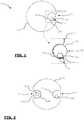
- Figure 1 schematically illustrates a first example of a detection cable 100 according to the invention.
- the detection cable 100 comprises a detection wire 102 and support core 104 which is insulated or non conductive.
- the detection wire 102 comprises a conductor 106 which is arranged off-centered in a non conductive envelope 108 such as the non conductive envelop 108 doesn't cover the conductor over its entire perimeter, i.e. there is a part 110 of the surface of the conductor 106 which is not covered by the envelop 108.
- the detection wire 102 is arranged in a shape 112 realized on the support core 104.
- the detection wire 102 is oriented in the shape 112, such as the part 110 of the conductor 106 which is not covered by the envelop 108 is disposed between the support core 104 end the envelop 108 in a liquid permeable way only.
- the off-centered arrangement of the conductor 106 and the orientation of the detection wire 102 in the shape 112 provides an electrical path only when a liquid penetrates in the small space 114 between the core 104 and the detection wire 102. Any conductive contaminants such as dust, metal braids or wires are unable to touch the conductor 106.
- Figure 2 schematically illustrates a second example of a detection cable 200 according to the invention.
- the cable 200 represented en figure 2 comprises all the components of the detection wire 100 represented on figure 1 .
- the detection cable 200 also comprises an electrical ground wire 202 arranged in a shape 204 realized on the support core 104.
- the electrical ground wire comprises a conductor 206 arranged in a conductor envelop 208.
- the liquid realizes an electrical path between the detection wire 102 and the ground wire 202.
- the detection wires of the figure 1 and figure 2 may also comprise continuity wires (non represented) for the detection wire 102 and the electrical ground wire 202.
- Figure 3 schematically illustrates a first example of a detection and localization cable 300 according to the invention.
- the cable 300 comprises a detection wire 102 identical to the detection wire of the cables 100 and 200 represented in figures 1 and 2 .
- the localization cable 300 also comprises a electrical continuity wire 302 for the detection wire 102 arranged in a shape 304 realized on the support core 104.
- the electrical continuity wire comprises a conductor 306 arranged in a non conductor envelop 308.
- the continuity wire 302 is connected to the detection wire at the far end of the cable 300 and is intended to be connected to a detection and localization unit at the cable's 300 near end.
- the continuity wire 302 constitutes an electrical continuity for the detection wire 102 from the far end of the cable 300 to the near end of the cable 300.
- the cable 300 may also be used only for the detection of the liquid leaks.
- All the cables 100, 200 et 300 may also comprise a data transmission bus arranged at the center of the support core 104.
- Figure 4 schematically illustrates a preferred embodiment of a detection and localization cable 400 according to the invention.
- the cable 400 comprises a support core 104 on which are arranged :
- the detection and the localization cable 400 also comprises a ground continuity wire 402 for the ground wire 202 arranged in a shape 404 realized on the support core 104.
- the ground continuity wire 402 comprises a conductor 306 arranged in a non conductor envelop 408.
- the ground continuity wire 402 is connected to the ground wire 202 at the far end of the cable 400 and is intended to be connected to a detection and localization unit at the cable's 300 near end.
- the ground continuity wire 402 constitutes a continuity of the electrical ground for the ground wire 202 from the far end of the cable 400 to the near end of the cable 400.
- the detection and the localization cable 400 may also comprise a data transmission bus 410 arranged in the support core 104.
- the data transmission bus may comprise one or several communication wires 412.
- the conductor 106 of the detection wire 102 (in all cables 100-400) is made of constantan.
- the envelop 208 of the ground wire 202 (in all cables 200 and 400) is made of any convenient for extrusion and electrically insulating polymer material such as PE, PVC, PP, PVDF, ETFE, etc. Color, flame retardant or other additives may also be used.
- Figure 5 schematically illustrates an example of a detection and localization module implementing the detection and localization cable of figure 4 .
- the module 500 comprises the detection and localization cable 400, means for the detection and the localization 502.
- the module 500 also comprises means 504 for hooking the detection and localization cable 400 to another similar or identical detection and localization cable.
- the enunciation and the localisation of a liquid leak is realized by monitoring the electrical resistance between the detection wire and the electrical ground.
- the precision of these direct methods may be affected by the quality of the instruments.
- the indirect methods are much simpler - it is only necessary to compare the value of the unknown resistance to another one, precise and with known value.
- the most common method is the Wheatstone bridge method as represented en figure 6 .
- the Wheatstone bridge 600 comprises a first variable resistance referenced R on the first branch of the bridge.
- Resistance R comprises several known resistances R1-R8 serially mounted.
- a switch is associated to each resistance R1 to R8 and the state of each switch is controlled digitally.
- the value of the resistance R is modified by modifying the state of a switch associated to one of the resistances R1 to R8.
- the Wheatstone bridge 600 comprises a second known resistance R9 mounted on the second branch of the bridge.
- the third branch of the Wheatstone bridge 600 is constituted by a resistance Rc1.
- the resistance Rc1 corresponds to the resistance of the detection wire between the near end of the cable and the location of the liquid leak. This resistance Rc1 is a linear function of the distance between the beginning of the sensing cable and the leak point.
- the last branch of the Wheatstone bridge 600 is constituted by a resistance Rc2 which corresponds to the resistance of the rest of the detection cable and the continuity cable for the detection cable.
- Rc1 and Rc2 The sum of Rc1 and Rc2 is known and corresponds to the total resistance of the detection wire and the continuity wire.
- Resistance Rx corresponds to the resistance caused by the liquid leak at the leak point.
- the voltage V1 is the voltage measured between the variable resistance R and resistance Rc1 and voltage V2 is the voltage measured between the resistance R9 and resistance Rc2.
- the bridge also comprises a voltage comparator 602, for example a galvanometer, which compares V1 to V2.
- V1 V2 and the bridge 600 is balanced.
- Another method is to start with the configuration of resistances R1-R8 corresponding to the highest resistance for resistance R and to reduce the resistance R step by step of a value ⁇ R corresponding to a known length L of the detection value.
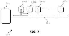
- Figure 7 schematically illustrates an example of an installation 700 according to the invention.
- the installation 700 comprises:
- the detection and localization modules 500a to 500c are serially connected.
- Each detection and localization module 500a-500x is interrogated one after the other. At first, the module 500a is interrogated. Then the module 500b is interrogated and so on.
- Each interrogated module 500 informs the support processing unit 702 if a liquid leak is detected or not. If a liquid leak is detected the location of the leak is given to the support processing unit.
- the invention is particularly adapted for the detection and the localization of leaks of water and other conductive liquids such as acids and bases.
Landscapes
- Physics & Mathematics (AREA)
- General Physics & Mathematics (AREA)
- Examining Or Testing Airtightness (AREA)
- Investigating Or Analyzing Materials By The Use Of Electric Means (AREA)
Claims (14)
- Kabel (100-400) zur Detektion von Leckagen leitender Flüssigkeiten, wobei das Kabel umfasst:- einen Detektionsdraht (102) mit einem Leiter (106), der in einer nichtleitenden Hülle (108) angeordnet ist, und- einen nichtleitenden Stützkern (104), umfassend ein zur Aufnahme des Detektionsdrahts (102) ausgebildetes Formelement (112) ;dadurch gekennzeichnet, dass- der Leiter (106) exzentrisch in der nichtleitenden Hülle (108) angeordnet ist, so dass ein Teil (114) der Oberfläche des Leiters (106) nicht durch die nichtleitende Hülle (108) abgedeckt ist, und- der Detektionsdraht (102) in dem Formelement (112) auf dem Stützkern (104) in einer solchen Ausrichtung angeordnet ist, dass der nicht abgedeckte Teil (114) des Leiters (106) flüssigkeitsdurchlässig zwischen dem Stützkern (104) und der nichtleitenden Hülle (108) angeordnet ist;wobei bei Auftreten einer Flüssigkeitsleckage diese Flüssigkeit einen elektrischen Pfad zwischen dem Leiter (106) und einer elektrischer Masse herstellt.
- Kabel (300, 400) gemäß Anspruch 1, dadurch gekennzeichnet, dass es ferner einen Kontinuitätsdraht (302) für den Detektionsdraht (102) umfasst, wobei der Kontinuitätsdraht (302)- an dem entfernten Ende des Detektionsdrahts mit dem Detektionsdraht (102) verbunden ist, und- zur Verbindung mit einer Detektionseinheit am nahen Ende des Detektionsdrahts vorgesehen ist.
- Kabel (200, 400) gemäß einem der vorhergehenden Ansprüche, dadurch gekennzeichnet, dass es ferner einen elektrischen Erdleiter (202) mit einem in einer Leiterhülle (208) angeordneten Leiter (206) umfasst, wobei bei Auftreten einer Flüssigkeitsleckage diese Flüssigkeit einen elektrischen Pfad zwischen dem Leiter (106) des Detektionsdrahts (102) und dem elektrischen Erdleiter (202) herstellt.
- Kabel (400) gemäß einem der vorhergehenden Ansprüche, dadurch gekennzeichnet, dass es ferner einen Kontinuitätsdraht (402) für den elektrischen Erdleiter (202) umfasst, wobei der Masse-Kontinuitätsdraht (402)- mit dem elektrischen Erdleiter (202) am entfernten Ende des elektrischen Erdleiters verbunden ist, und- zur Verbindung mit einer Detektionseinheit am nahen Ende des elektrischen Erdleiters vorgesehen ist.
- Kabel (300, 400) zur Detektion und Lokalisierung von Flüssigkeitsleckagen, wobei das Kabel umfasst- einen Detektionsdraht (102) mit einem Leiter (106), der in einer nichtleitenden Hülle (108) angeordnet ist;- einen Kontinuitätsdraht (302) für den Detektionsdraht (102), wobei der Kontinuitätsdraht (302)- am entfernten Ende des Detektionsdrahts mit dem Detektionsdraht (102) verbunden ist, und- zur Verbindung mit einer Detektionseinheit am nahen Ende des Detektionsdrahts vorgesehen ist; und- einen nichtleitenden Stützkern (104), umfassend ein zur Aufnahme des Detektionsdrahts (102) ausgebildetes Formelement (112);dadurch gekennzeichnet, dass- der Leiter (106) exzentrisch in der nichtleitenden Hülle (108) angeordnet ist, so dass ein Teil (114) der Oberfläche des Leiters (106) nicht durch die nichtleitende Hülle (108) abgedeckt ist, und- der Detektionsdraht (102) in dem Formelement (112) auf dem Stützkern (104) in einer solchen Ausrichtung angeordnet ist, dass der nicht abgedeckte Teil (114) des Leiters (106) flüssigkeitsdurchlässig zwischen dem Stützkern (104) und der nichtleitenden Hülle (108) angeordnet ist;wobei bei Auftreten einer Flüssigkeitsleckage diese Flüssigkeit einen elektrischen Pfad zwischen dem Leiter (106) und einer elektrischer Masse herstellt.
- Kabel (400) gemäß Anspruch 5, dadurch gekennzeichnet, dass es ferner einen elektrischen Erdleiter (202) mit einem in einer Leiterhülle (208) angeordneten Leiter (206) umfasst, wobei bei Auftreten einer Flüssigkeitsleckage diese Flüssigkeit einen elektrischen Pfad zwischen dem Leiter (106) des Detektionsdrahts (102) und dem elektrischen Erdleiter (202) herstellt.
- Kabel (400) gemäß einem der Ansprüche 5 oder 6, dadurch gekennzeichnet, dass es ferner einen Kontinuitätsdraht (402) für den elektrischen Erdleiter (202) umfasst, wobei der Masse-Kontinuitätsdraht (402)- mit dem elektrischen Erdleiter (202) am entfernten Ende des elektrischen Erdleiters verbunden ist, und- zur Verbindung mit einer Detektionseinheit am nahen Ende des elektrischen Erdleiters vorgesehen ist.
- Kabel gemäß einem der vorhergehenden Ansprüche, dadurch gekennzeichnet, dass der Leiter (106) des Detektionsdrahts (102) aus Konstantan besteht.
- Kabel gemäß einem der Ansprüche 3 oder 6, dadurch gekennzeichnet, dass die leitende Hülle (208) des elektrischen Erdleiters (202) ein leitendes Polymer umfasst.
- Modul (500) zur Detektion von Flüssigkeitsleckagen, umfassend- wenigstens ein Detektionskabel (100-400) gemäß einem der Ansprüche 1 bis 4, 8 oder 9, und- eine Detektionseinheit (502) für wenigstens ein Detektionskabel (100-400).
- Modul (500) zur Detektion und Lokalisierung von Flüssigkeitsleckagen, umfassend- wenigstens ein Detektions- und Lokalisierungskabel (300, 400) gemäß einem der Ansprüche 5 bis 7, 8 oder 9 und- eine Detektions- und Lokalisierungseinheit (502) für wenigstens ein Detektions- und Lokalisierungskabel (300, 400) .
- Anlage (700) zur Detektion von Flüssigkeitsleckagen, umfassend- eine Hilfs-Recheneinheit (702),- einen Datenübertragungsbus (704), und- wenigstens ein Detektionsmodul (500) gemäß Anspruch 10.
- Anlage (700) zur Detektion und Lokalisierung von Flüssigkeitsleckagen, umfassend- eine Hilfs-Recheneinheit (702),- einen Datenübertragungsbus (704), und- wenigstens ein Detektions- und Lokalisierungsmodul (500) gemäß Anspruch 11.
- Anlage gemäß einem der Ansprüche 12 oder 13, dadurch gekennzeichnet, dass der Datenübertragungsbus innerhalb des nichtleitenden Stützkerns (104) des Detektionskabels oder des Detektions- und Lokalisierungskabel angeordnet ist.
Priority Applications (1)
| Application Number | Priority Date | Filing Date | Title |
|---|---|---|---|
| EP09306176.0A EP2330397B1 (de) | 2009-12-03 | 2009-12-03 | Kabel, Modul und Installation zur Erkennung und Lokalisierung von Lecks von leitenden Flüssigkeiten |
Applications Claiming Priority (1)
| Application Number | Priority Date | Filing Date | Title |
|---|---|---|---|
| EP09306176.0A EP2330397B1 (de) | 2009-12-03 | 2009-12-03 | Kabel, Modul und Installation zur Erkennung und Lokalisierung von Lecks von leitenden Flüssigkeiten |
Publications (2)
| Publication Number | Publication Date |
|---|---|
| EP2330397A1 EP2330397A1 (de) | 2011-06-08 |
| EP2330397B1 true EP2330397B1 (de) | 2018-02-21 |
Family
ID=42101853
Family Applications (1)
| Application Number | Title | Priority Date | Filing Date |
|---|---|---|---|
| EP09306176.0A Active EP2330397B1 (de) | 2009-12-03 | 2009-12-03 | Kabel, Modul und Installation zur Erkennung und Lokalisierung von Lecks von leitenden Flüssigkeiten |
Country Status (1)
| Country | Link |
|---|---|
| EP (1) | EP2330397B1 (de) |
Families Citing this family (3)
| Publication number | Priority date | Publication date | Assignee | Title |
|---|---|---|---|---|
| FR2998753B1 (fr) * | 2012-11-28 | 2016-01-01 | Ttk | Module, circuit et procede de communication pour dispositif de detection et capteur comprenant un tel module. |
| FR3136848B1 (fr) | 2022-06-16 | 2025-02-07 | Ttk | Procédé de codage de conducteurs de communication d’un capteur linéaire appartenant à un système. |
| FR3136854A1 (fr) | 2022-06-16 | 2023-12-22 | Ttk | Installation polyvalente de détection et de localisation de fuites de liquide. |
Family Cites Families (8)
| Publication number | Priority date | Publication date | Assignee | Title |
|---|---|---|---|---|
| JPS6440057U (de) * | 1987-09-04 | 1989-03-09 | ||
| JPS62285053A (ja) * | 1986-06-04 | 1987-12-10 | Daiko Denki Kk | 漏水検知帯及びその製造方法 |
| DE8714044U1 (de) * | 1987-10-20 | 1988-02-25 | Salzgitter Elektronik GmbH, 2300 Kiel | Überwachungsleitung zum Feststellen von Fehler- oder Leckstellen an Transportleitungen für flüssige Medien |
| US5191292A (en) * | 1990-04-26 | 1993-03-02 | Raychem Corporation | Method of making a sensor cable |
| GB2275555A (en) * | 1993-02-25 | 1994-08-31 | Northern Telecom Ltd | Sensor cable |
| FR2709347B1 (fr) * | 1993-08-27 | 1995-10-13 | Ttk | Installation de détection et de localisation de fuites de liquide. |
| US6144209A (en) * | 1998-04-07 | 2000-11-07 | Raymond & Lae Engineering, Inc. | Fluid detection cable |
| JP4780970B2 (ja) * | 2005-02-10 | 2011-09-28 | スリーエム イノベイティブ プロパティズ カンパニー | 漏水センサ |
-
2009
- 2009-12-03 EP EP09306176.0A patent/EP2330397B1/de active Active
Non-Patent Citations (1)
| Title |
|---|
| None * |
Also Published As
| Publication number | Publication date |
|---|---|
| EP2330397A1 (de) | 2011-06-08 |
Similar Documents
| Publication | Publication Date | Title |
|---|---|---|
| US10488273B2 (en) | Measuring arrangement and temperature-measuring method, and sensor cable for such a measuring arrangement | |
| RU2605081C2 (ru) | Способ контроля нескольких электрических проводов электроэнергии жгута проводов | |
| CN112823104B (zh) | 用于充电站的线路套组、充电站 | |
| US9513185B2 (en) | Inflatable detecting element, modular detection cable and detection system for detecting leaks of nonconductive liquid | |
| WO2014200375A1 (en) | Method and system for monitoring electrical wire aging | |
| US20170138880A1 (en) | Aircraft rescue hoist rope designed for continuous inspection | |
| EP2330397B1 (de) | Kabel, Modul und Installation zur Erkennung und Lokalisierung von Lecks von leitenden Flüssigkeiten | |
| CN204215023U (zh) | 终端充电参数测试线 | |
| CN104484973B (zh) | 一种复合线缆感温火灾探测器 | |
| KR101984432B1 (ko) | 케이블의 열화상태 진단장치 및 진단방법 | |
| EP0356017A2 (de) | Gerät zum Erkennen von Flüssigkeitslecks | |
| EP0144211A2 (de) | Fühlerkabel | |
| US4843327A (en) | Branched sensor system | |
| WO2021038454A3 (en) | Textile sensor for the detection of liquids and temperature, and method of making same | |
| JP6297678B2 (ja) | 電気機械の固定子巻線バーの素線間短絡試験 | |
| US4931741A (en) | Branched sensor system | |
| CN110954756A (zh) | 一种三相电缆鉴相方法及装置 | |
| CN215813274U (zh) | 断点探测包套及包括其的电缆 | |
| CN204423975U (zh) | 一种自测温电缆 | |
| CN109060220A (zh) | 一种电缆附件界面压力检测方法和装置 | |
| JP6069051B2 (ja) | 電力ケーブル高抵抗絶縁不良箇所標定方法及び装置 | |
| CN104198075A (zh) | 一种可恢复式线型温度检测系统 | |
| US20250286326A1 (en) | System of cable and connectors with integrated sensors | |
| CN219533364U (zh) | 一种监测电缆短路的装置 | |
| CN104198076A (zh) | 一种多功能线型感温仪器 |
Legal Events
| Date | Code | Title | Description |
|---|---|---|---|
| PUAI | Public reference made under article 153(3) epc to a published international application that has entered the european phase |
Free format text: ORIGINAL CODE: 0009012 |
|
| AK | Designated contracting states |
Kind code of ref document: A1 Designated state(s): AT BE BG CH CY CZ DE DK EE ES FI FR GB GR HR HU IE IS IT LI LT LU LV MC MK MT NL NO PL PT RO SE SI SK SM TR |
|
| AX | Request for extension of the european patent |
Extension state: AL BA RS |
|
| 17P | Request for examination filed |
Effective date: 20111205 |
|
| RAP1 | Party data changed (applicant data changed or rights of an application transferred) |
Owner name: TTK |
|
| GRAP | Despatch of communication of intention to grant a patent |
Free format text: ORIGINAL CODE: EPIDOSNIGR1 |
|
| STAA | Information on the status of an ep patent application or granted ep patent |
Free format text: STATUS: GRANT OF PATENT IS INTENDED |
|
| INTG | Intention to grant announced |
Effective date: 20171005 |
|
| GRAS | Grant fee paid |
Free format text: ORIGINAL CODE: EPIDOSNIGR3 |
|
| GRAA | (expected) grant |
Free format text: ORIGINAL CODE: 0009210 |
|
| STAA | Information on the status of an ep patent application or granted ep patent |
Free format text: STATUS: THE PATENT HAS BEEN GRANTED |
|
| AK | Designated contracting states |
Kind code of ref document: B1 Designated state(s): AT BE BG CH CY CZ DE DK EE ES FI FR GB GR HR HU IE IS IT LI LT LU LV MC MK MT NL NO PL PT RO SE SI SK SM TR |
|
| REG | Reference to a national code |
Ref country code: GB Ref legal event code: FG4D |
|
| REG | Reference to a national code |
Ref country code: CH Ref legal event code: EP |
|
| REG | Reference to a national code |
Ref country code: DE Ref legal event code: R096 Ref document number: 602009050828 Country of ref document: DE Ref country code: AT Ref legal event code: REF Ref document number: 972280 Country of ref document: AT Kind code of ref document: T Effective date: 20180315 |
|
| REG | Reference to a national code |
Ref country code: IE Ref legal event code: FG4D |
|
| REG | Reference to a national code |
Ref country code: NL Ref legal event code: MP Effective date: 20180221 |
|
| REG | Reference to a national code |
Ref country code: LT Ref legal event code: MG4D |
|
| REG | Reference to a national code |
Ref country code: AT Ref legal event code: MK05 Ref document number: 972280 Country of ref document: AT Kind code of ref document: T Effective date: 20180221 |
|
| PG25 | Lapsed in a contracting state [announced via postgrant information from national office to epo] |
Ref country code: NO Free format text: LAPSE BECAUSE OF FAILURE TO SUBMIT A TRANSLATION OF THE DESCRIPTION OR TO PAY THE FEE WITHIN THE PRESCRIBED TIME-LIMIT Effective date: 20180521 Ref country code: FI Free format text: LAPSE BECAUSE OF FAILURE TO SUBMIT A TRANSLATION OF THE DESCRIPTION OR TO PAY THE FEE WITHIN THE PRESCRIBED TIME-LIMIT Effective date: 20180221 Ref country code: CY Free format text: LAPSE BECAUSE OF FAILURE TO SUBMIT A TRANSLATION OF THE DESCRIPTION OR TO PAY THE FEE WITHIN THE PRESCRIBED TIME-LIMIT Effective date: 20180221 Ref country code: HR Free format text: LAPSE BECAUSE OF FAILURE TO SUBMIT A TRANSLATION OF THE DESCRIPTION OR TO PAY THE FEE WITHIN THE PRESCRIBED TIME-LIMIT Effective date: 20180221 Ref country code: NL Free format text: LAPSE BECAUSE OF FAILURE TO SUBMIT A TRANSLATION OF THE DESCRIPTION OR TO PAY THE FEE WITHIN THE PRESCRIBED TIME-LIMIT Effective date: 20180221 Ref country code: LT Free format text: LAPSE BECAUSE OF FAILURE TO SUBMIT A TRANSLATION OF THE DESCRIPTION OR TO PAY THE FEE WITHIN THE PRESCRIBED TIME-LIMIT Effective date: 20180221 Ref country code: ES Free format text: LAPSE BECAUSE OF FAILURE TO SUBMIT A TRANSLATION OF THE DESCRIPTION OR TO PAY THE FEE WITHIN THE PRESCRIBED TIME-LIMIT Effective date: 20180221 |
|
| PG25 | Lapsed in a contracting state [announced via postgrant information from national office to epo] |
Ref country code: GR Free format text: LAPSE BECAUSE OF FAILURE TO SUBMIT A TRANSLATION OF THE DESCRIPTION OR TO PAY THE FEE WITHIN THE PRESCRIBED TIME-LIMIT Effective date: 20180522 Ref country code: SE Free format text: LAPSE BECAUSE OF FAILURE TO SUBMIT A TRANSLATION OF THE DESCRIPTION OR TO PAY THE FEE WITHIN THE PRESCRIBED TIME-LIMIT Effective date: 20180221 Ref country code: LV Free format text: LAPSE BECAUSE OF FAILURE TO SUBMIT A TRANSLATION OF THE DESCRIPTION OR TO PAY THE FEE WITHIN THE PRESCRIBED TIME-LIMIT Effective date: 20180221 Ref country code: AT Free format text: LAPSE BECAUSE OF FAILURE TO SUBMIT A TRANSLATION OF THE DESCRIPTION OR TO PAY THE FEE WITHIN THE PRESCRIBED TIME-LIMIT Effective date: 20180221 Ref country code: BG Free format text: LAPSE BECAUSE OF FAILURE TO SUBMIT A TRANSLATION OF THE DESCRIPTION OR TO PAY THE FEE WITHIN THE PRESCRIBED TIME-LIMIT Effective date: 20180521 |
|
| PG25 | Lapsed in a contracting state [announced via postgrant information from national office to epo] |
Ref country code: PL Free format text: LAPSE BECAUSE OF FAILURE TO SUBMIT A TRANSLATION OF THE DESCRIPTION OR TO PAY THE FEE WITHIN THE PRESCRIBED TIME-LIMIT Effective date: 20180221 Ref country code: IT Free format text: LAPSE BECAUSE OF FAILURE TO SUBMIT A TRANSLATION OF THE DESCRIPTION OR TO PAY THE FEE WITHIN THE PRESCRIBED TIME-LIMIT Effective date: 20180221 Ref country code: RO Free format text: LAPSE BECAUSE OF FAILURE TO SUBMIT A TRANSLATION OF THE DESCRIPTION OR TO PAY THE FEE WITHIN THE PRESCRIBED TIME-LIMIT Effective date: 20180221 Ref country code: EE Free format text: LAPSE BECAUSE OF FAILURE TO SUBMIT A TRANSLATION OF THE DESCRIPTION OR TO PAY THE FEE WITHIN THE PRESCRIBED TIME-LIMIT Effective date: 20180221 |
|
| REG | Reference to a national code |
Ref country code: DE Ref legal event code: R097 Ref document number: 602009050828 Country of ref document: DE |
|
| PG25 | Lapsed in a contracting state [announced via postgrant information from national office to epo] |
Ref country code: CZ Free format text: LAPSE BECAUSE OF FAILURE TO SUBMIT A TRANSLATION OF THE DESCRIPTION OR TO PAY THE FEE WITHIN THE PRESCRIBED TIME-LIMIT Effective date: 20180221 Ref country code: DK Free format text: LAPSE BECAUSE OF FAILURE TO SUBMIT A TRANSLATION OF THE DESCRIPTION OR TO PAY THE FEE WITHIN THE PRESCRIBED TIME-LIMIT Effective date: 20180221 Ref country code: SM Free format text: LAPSE BECAUSE OF FAILURE TO SUBMIT A TRANSLATION OF THE DESCRIPTION OR TO PAY THE FEE WITHIN THE PRESCRIBED TIME-LIMIT Effective date: 20180221 Ref country code: SK Free format text: LAPSE BECAUSE OF FAILURE TO SUBMIT A TRANSLATION OF THE DESCRIPTION OR TO PAY THE FEE WITHIN THE PRESCRIBED TIME-LIMIT Effective date: 20180221 |
|
| PLBE | No opposition filed within time limit |
Free format text: ORIGINAL CODE: 0009261 |
|
| STAA | Information on the status of an ep patent application or granted ep patent |
Free format text: STATUS: NO OPPOSITION FILED WITHIN TIME LIMIT |
|
| 26N | No opposition filed |
Effective date: 20181122 |
|
| PG25 | Lapsed in a contracting state [announced via postgrant information from national office to epo] |
Ref country code: SI Free format text: LAPSE BECAUSE OF FAILURE TO SUBMIT A TRANSLATION OF THE DESCRIPTION OR TO PAY THE FEE WITHIN THE PRESCRIBED TIME-LIMIT Effective date: 20180221 |
|
| REG | Reference to a national code |
Ref country code: CH Ref legal event code: PL |
|
| PG25 | Lapsed in a contracting state [announced via postgrant information from national office to epo] |
Ref country code: MC Free format text: LAPSE BECAUSE OF FAILURE TO SUBMIT A TRANSLATION OF THE DESCRIPTION OR TO PAY THE FEE WITHIN THE PRESCRIBED TIME-LIMIT Effective date: 20180221 Ref country code: LU Free format text: LAPSE BECAUSE OF NON-PAYMENT OF DUE FEES Effective date: 20181203 |
|
| REG | Reference to a national code |
Ref country code: IE Ref legal event code: MM4A |
|
| REG | Reference to a national code |
Ref country code: BE Ref legal event code: MM Effective date: 20181231 |
|
| PG25 | Lapsed in a contracting state [announced via postgrant information from national office to epo] |
Ref country code: IE Free format text: LAPSE BECAUSE OF NON-PAYMENT OF DUE FEES Effective date: 20181203 |
|
| PG25 | Lapsed in a contracting state [announced via postgrant information from national office to epo] |
Ref country code: BE Free format text: LAPSE BECAUSE OF NON-PAYMENT OF DUE FEES Effective date: 20181231 |
|
| PG25 | Lapsed in a contracting state [announced via postgrant information from national office to epo] |
Ref country code: CH Free format text: LAPSE BECAUSE OF NON-PAYMENT OF DUE FEES Effective date: 20181231 Ref country code: LI Free format text: LAPSE BECAUSE OF NON-PAYMENT OF DUE FEES Effective date: 20181231 |
|
| PG25 | Lapsed in a contracting state [announced via postgrant information from national office to epo] |
Ref country code: MT Free format text: LAPSE BECAUSE OF NON-PAYMENT OF DUE FEES Effective date: 20181203 |
|
| PG25 | Lapsed in a contracting state [announced via postgrant information from national office to epo] |
Ref country code: TR Free format text: LAPSE BECAUSE OF FAILURE TO SUBMIT A TRANSLATION OF THE DESCRIPTION OR TO PAY THE FEE WITHIN THE PRESCRIBED TIME-LIMIT Effective date: 20180221 |
|
| PG25 | Lapsed in a contracting state [announced via postgrant information from national office to epo] |
Ref country code: PT Free format text: LAPSE BECAUSE OF FAILURE TO SUBMIT A TRANSLATION OF THE DESCRIPTION OR TO PAY THE FEE WITHIN THE PRESCRIBED TIME-LIMIT Effective date: 20180221 |
|
| PG25 | Lapsed in a contracting state [announced via postgrant information from national office to epo] |
Ref country code: HU Free format text: LAPSE BECAUSE OF FAILURE TO SUBMIT A TRANSLATION OF THE DESCRIPTION OR TO PAY THE FEE WITHIN THE PRESCRIBED TIME-LIMIT; INVALID AB INITIO Effective date: 20091203 Ref country code: MK Free format text: LAPSE BECAUSE OF NON-PAYMENT OF DUE FEES Effective date: 20180221 |
|
| PG25 | Lapsed in a contracting state [announced via postgrant information from national office to epo] |
Ref country code: IS Free format text: LAPSE BECAUSE OF FAILURE TO SUBMIT A TRANSLATION OF THE DESCRIPTION OR TO PAY THE FEE WITHIN THE PRESCRIBED TIME-LIMIT Effective date: 20180621 |
|
| P01 | Opt-out of the competence of the unified patent court (upc) registered |
Effective date: 20230516 |
|
| PGFP | Annual fee paid to national office [announced via postgrant information from national office to epo] |
Ref country code: GB Payment date: 20251229 Year of fee payment: 17 |
|
| PGFP | Annual fee paid to national office [announced via postgrant information from national office to epo] |
Ref country code: FR Payment date: 20251223 Year of fee payment: 17 |
|
| PGFP | Annual fee paid to national office [announced via postgrant information from national office to epo] |
Ref country code: DE Payment date: 20260127 Year of fee payment: 17 |