EP2329907A1 - Laser processing apparatus and processing method employed therein - Google Patents
Laser processing apparatus and processing method employed therein Download PDFInfo
- Publication number
- EP2329907A1 EP2329907A1 EP09797780A EP09797780A EP2329907A1 EP 2329907 A1 EP2329907 A1 EP 2329907A1 EP 09797780 A EP09797780 A EP 09797780A EP 09797780 A EP09797780 A EP 09797780A EP 2329907 A1 EP2329907 A1 EP 2329907A1
- Authority
- EP
- European Patent Office
- Prior art keywords
- light
- processed
- laser processing
- processing apparatus
- guides
- Prior art date
- Legal status (The legal status is an assumption and is not a legal conclusion. Google has not performed a legal analysis and makes no representation as to the accuracy of the status listed.)
- Withdrawn
Links
- 238000003672 processing method Methods 0.000 title claims description 28
- 238000001514 detection method Methods 0.000 claims description 6
- 230000001678 irradiating effect Effects 0.000 claims description 4
- 239000013307 optical fiber Substances 0.000 abstract description 87
- 238000000034 method Methods 0.000 description 51
- 230000005855 radiation Effects 0.000 description 17
- 239000000835 fiber Substances 0.000 description 10
- 230000004048 modification Effects 0.000 description 5
- 238000012986 modification Methods 0.000 description 5
- 229910000679 solder Inorganic materials 0.000 description 4
- 230000003287 optical effect Effects 0.000 description 3
- 230000035945 sensitivity Effects 0.000 description 3
- 239000000758 substrate Substances 0.000 description 3
- 239000004593 Epoxy Substances 0.000 description 2
- ATJFFYVFTNAWJD-UHFFFAOYSA-N Tin Chemical compound [Sn] ATJFFYVFTNAWJD-UHFFFAOYSA-N 0.000 description 2
- 230000000694 effects Effects 0.000 description 2
- 230000002708 enhancing effect Effects 0.000 description 2
- 239000011521 glass Substances 0.000 description 2
- 230000007547 defect Effects 0.000 description 1
- 230000002950 deficient Effects 0.000 description 1
- 229910052736 halogen Inorganic materials 0.000 description 1
- 150000002367 halogens Chemical class 0.000 description 1
- 239000004065 semiconductor Substances 0.000 description 1
- 239000007787 solid Substances 0.000 description 1
- 238000002560 therapeutic procedure Methods 0.000 description 1
Images




Classifications
-
- G—PHYSICS
- G02—OPTICS
- G02B—OPTICAL ELEMENTS, SYSTEMS OR APPARATUS
- G02B6/00—Light guides; Structural details of arrangements comprising light guides and other optical elements, e.g. couplings
- G02B6/04—Light guides; Structural details of arrangements comprising light guides and other optical elements, e.g. couplings formed by bundles of fibres
-
- B—PERFORMING OPERATIONS; TRANSPORTING
- B23—MACHINE TOOLS; METAL-WORKING NOT OTHERWISE PROVIDED FOR
- B23K—SOLDERING OR UNSOLDERING; WELDING; CLADDING OR PLATING BY SOLDERING OR WELDING; CUTTING BY APPLYING HEAT LOCALLY, e.g. FLAME CUTTING; WORKING BY LASER BEAM
- B23K26/00—Working by laser beam, e.g. welding, cutting or boring
- B23K26/02—Positioning or observing the workpiece, e.g. with respect to the point of impact; Aligning, aiming or focusing the laser beam
- B23K26/03—Observing, e.g. monitoring, the workpiece
- B23K26/032—Observing, e.g. monitoring, the workpiece using optical means
-
- G—PHYSICS
- G01—MEASURING; TESTING
- G01N—INVESTIGATING OR ANALYSING MATERIALS BY DETERMINING THEIR CHEMICAL OR PHYSICAL PROPERTIES
- G01N21/00—Investigating or analysing materials by the use of optical means, i.e. using sub-millimetre waves, infrared, visible or ultraviolet light
- G01N21/84—Systems specially adapted for particular applications
- G01N21/88—Investigating the presence of flaws or contamination
- G01N21/95—Investigating the presence of flaws or contamination characterised by the material or shape of the object to be examined
- G01N21/956—Inspecting patterns on the surface of objects
- G01N21/95684—Patterns showing highly reflecting parts, e.g. metallic elements
-
- B—PERFORMING OPERATIONS; TRANSPORTING
- B23—MACHINE TOOLS; METAL-WORKING NOT OTHERWISE PROVIDED FOR
- B23K—SOLDERING OR UNSOLDERING; WELDING; CLADDING OR PLATING BY SOLDERING OR WELDING; CUTTING BY APPLYING HEAT LOCALLY, e.g. FLAME CUTTING; WORKING BY LASER BEAM
- B23K2101/00—Articles made by soldering, welding or cutting
- B23K2101/36—Electric or electronic devices
- B23K2101/40—Semiconductor devices
Definitions
- the present invention relates to a laser processing apparatus and a processing method employed therein.
- a laser processing apparatus disclosed in the literature has a laser light source emitting bonding light to a bonding portion of a lead and a bonding land of a substrate; another laser light source emitting determining light; a determination apparatus determining the bonding state of the bonding portion; and a CCD camera identifying a defect of the lead.
- the bonding portion is irradiated with the bonding light, and then irradiated with the determining light. Reflected light and radiant light from the determining light are received at the determination apparatus, which then determines the bonding state.
- the CCD camera identifies a defective lead, thus enhancing the reliability of mounting.
- the conventional laser processing apparatus is not provided with a means identifying an adjacent object disposed in the vicinity of the bonding portion, a means controlling irradiation power with the bonding light according to the type of the adjacent object, for example.
- Such an apparatus may erroneously process the adjacent object, failing to improve processing accuracy.
- An object of the present invention is to provide a laser processing apparatus and a laser processing method having high processing accuracy.
- the present invention provides a laser processing apparatus scanning and processing an object to be processed with processing light.
- the laser processing apparatus includes a first light emitting unit emitting processing light; a first light guide conducting the processing light emitted from the first light emitting unit to an object to be processed; a second light emitting unit emitting observation light that observes the object to be processed; a plurality of second light guides conducting the observation light emitted from the second light emitting unit to the object to be processed; a third light guide conducting light having a plurality of wavelengths generated at the object to be processed; a detecting unit detecting the light having a plurality of wavelengths conducted by the third light guide; and a control unit controlling a light emitting state of the first light emitting unit, based on a result of detection by the detecting unit.
- the second light guides are categorized into at least two groups, and conduct the observation light to the object to be processed every group, the observation light being emitted from the second light emitting unit.
- the second light guides are categorized into at least two groups, and conduct the observation light to the object to be processed every group, the observation light being emitted from the second light emitting unit.
- differentiating a radiation timing of the observation light emitted from each group allows identification of an object to be irradiated respectively with the observation light emitted every group.
- a position of the identified object corresponds to a disposed position of each group. The position of the identified object can thus be easily determined, based on the disposed position of the group. Accordingly, it is possible to control radiation power of the processing light according to the type of the identified object, or to adjust a radiation time of the processing light according to the position of the identified object. This can prevent the identified object from being processed erroneously, and thus can enhance processing accuracy.
- the second light guides are categorized into four groups; and that, at an emission end of the first light guide, the second light guides categorized into the four groups are disposed a forward direction, a backward direction, left hand, and right hand relative to a scanning direction of the processing light emitted from the first light guide, such that the second light guides surround the first light guide.
- the second light guides categorized into the four groups in sequence, conduct the observation light emitted from the second light emitting unit to the object to be processed. Thereby, an object disposed in the forward direction, backward direction, left hand, and right hand to the processed area can easily be identified.
- the present invention provides a laser processing apparatus scanning and processing an object to be processed with processing light.
- the laser processing apparatus includes a first light emitting unit emitting processing light; a first light guide conducting the processing light emitted from the first light emitting unit to an object to be processed; a second light emitting unit emitting observation light that observes the object to be processed; a second light guide conducting the observation light emitted from the second light emitting unit to the object to be processed; a plurality of third light guides conducting light having a plurality of wavelengths generated at the object to be processed; a detecting unit detecting the light having a plurality of wavelengths conducted by the third light guides; and a control unit controlling a light emitting state of the first light emitting unit, based on a result of detection by the detecting unit.
- the third light guides are categorized into at least two groups, and conduct the light every group, the light having a plurality of wavelengths generated at the object to be processed.
- the third light guides are categorized into at least two groups, and conduct the light every group, the light having a plurality of wavelengths generated at the object to be processed.
- differentiating a timing to conduct the light by each group allows identification of an object corresponding to the third light guides of each group respectively.
- a position of the identified object corresponds to a disposed position of each group. The position of the identified object can thus be easily determined, based on the disposed position of the group. Accordingly, it is possible to control radiation power of the processing light according to the type of the identified object, or to adjust a radiation time of the processing light according to the position of the identified object. This can prevent the identified object from being processed erroneously, and thus can enhance processing accuracy.
- the third light guides are categorized into four groups; and that, at an emission end of the first light guide, the third light guides categorized into the four groups are disposed a forward direction, a backward direction, left hand, and right hand relative to a scanning direction of the processing light emitted from the first light guide, such that the third light guides surround the first light guide.
- the third light guides surround the first light guide.
- the third light guides categorized into the four groups in sequence, conduct the light having a plurality of wavelengths generated at the object to be processed. Thereby, an object disposed over the forward direction, backward direction, left hand, and right hand to the processed area can easily be identified.
- the detecting unit includes a detecting element corresponding to each group of the third light guides. This enhances accuracy of the light detection.
- the detecting unit includes a single detecting element and light path changing means allowing the light conducted by the third light guides to enter the detecting element. This can simplify a configuration of the detecting unit, and thus can reduce cost of the apparatus as a whole.
- the present invention provides a laser processing method using the laser processing apparatus described above.
- the laser processing method includes (1) irradiating the object to be processed with the observation light from every group of the second light guides; (2) detecting the light having a plurality of wavelengths generated at the object to be processed, and identifying the object as an object to be irradiated or not, based on properties of the detected light; and (3) controlling the processing light based on a result of identification of the object to be irradiated, and processing the object.
- the object to be processed is irradiated with the observation light from every group of the second light guides, and thereby the type and position of the object disposed in the vicinity of the processed area can easily be specified. It is then possible to control radiation power of the processing light according to the type of the identified object, or to adjust a radiation time of the processing light according to the position of the identified object. This can prevent the identified object from being processed erroneously, and thus can enhance processing accuracy.
- step (1) the group of the second light guides disposed forward in the scanning direction of the processing light is used alone to radiate the observation light onto the object to be processed. This identifies an object disposed forward in the scanning direction of the processing light alone, and thus can contribute to an increased processing speed.
- the present invention provides a laser processing method using the laser processing apparatus described above.
- the laser processing method includes (1) irradiating the object to be processed with the observation light; (2) detecting the light having a plurality of wavelengths generated at the object to be processed, using each group of the third light guides, and identifying the object as an object to be irradiated or not, based on properties of the detected light; and (3) controlling the processing light based on a result of identification of the object to be irradiated, and processing the object.
- the light having a plurality of wavelengths generated at the object to be processed is detected by each group of the third light guides, and thereby the type and position of the object disposed in the vicinity of the processed area can easily be specified. It is then possible to control radiation power of the processing light according to the type of the identified object, or to adjust a radiation time of the processing light according to the position of the identified object. This can prevent the identified object from being processed erroneously, and thus can enhance processing accuracy.
- step (2) the group of the third light guides disposed forward in the scanning direction of the processing light is used alone to detect the light having a plurality of wavelengths generated at the object to be processed. This identifies an object disposed forward in the scanning direction of the processing light alone, and thus can contribute to an increased processing speed.
- the present invention provides the laser processing apparatus and the laser processing method capable of enhancing processing accuracy.
- FIG. 1 is a schematic view illustrating a configuration of a laser processing apparatus according to a first embodiment.
- a laser processing apparatus 1 which is used for processing electronic components, has a processing light source (first light emitting unit) 3 emitting processing light to process an electronic component (object to be processed) 2; an observation light emitting unit (second light emitting unit) 4 emitting observation light to observe the electronic component 2; a detecting unit 5 detecting light having a plurality of wavelengths generated at the electronic component 2; and a control unit 31 controlling a light emitting state of the processing light source 3.
- first light emitting unit first light emitting unit
- second light emitting unit 4 emitting observation light to observe the electronic component 2
- a detecting unit 5 detecting light having a plurality of wavelengths generated at the electronic component 2
- a control unit 31 controlling a light emitting state of the processing light source 3.
- the processing light source 3 includes a semiconductor laser element outputting laser light having a specific wavelength of 408 nm.
- the processing light emitted from the processing light source 3 is conducted to the electronic component 2 by an optical fiber (first light guide) 6 optically connected to the processing light source 3.
- the observation light emitting unit 4 which emits the observation light to observe the electronic component 2, has two types of light sources having different central wavelengths. Specifically, the observation light emitting unit 4 includes four first observation light sources 7 outputting laser light having a wavelength of 445 nm, and four second observation light sources 8 outputting laser light having a wavelength of 660 nm.
- the four first observation light sources 7 are optically connected to four optical fibers (second light guides) 9; and the four second observation light sources 8 are optically connected to four optical fibers (second light guides) 10.
- the optical fibers 9 and 10 are also connected to a multiplexing unit 11.
- the multiplexing unit 11 multiplexes the light having a wavelength of 445 nm conducted by the optical fibers 9 and the light having a wavelength of 660 nm conducted by the optical fibers 10 at a ratio of one to one, and then outputs the multiplexed light to the electronic component 2 by way of four optical fibers (second light guides) 12.
- the detecting unit 5 is provided with a first detecting element 13 and a second detecting element 14, which have different light-receiving sensitivities depending on the wavelength.
- the first detecting element 13 has a high light-receiving sensitivity to light having a wavelength of 445 nm; and the second detecting element 14 has a high light-receiving sensitivity to light having a wavelength of 660 nm.
- the first detecting element 13 and the second detecting element 14 are optically connected to optical fibers (third light guides) 15 and 16, respectively.
- the first detecting element 13 and the second detecting element 14 detect the intensity of different wavelengths of light conducted by the optical fibers 15 and 16, respectively, and output the results of detection to the control unit 31.
- the detecting unit 5 may be provided with an optical filter and a plurality of detecting elements, the optical filter transmitting or reflecting light having different center wavelengths, the detecting elements detecting the intensity of the light which has been transmitted or reflected by the optical filter and has different center wavelengths.
- the detecting unit 5 may be provided with a light path changing means and detecting elements, the light path changing means separating or switching the light path from the third light guide to the detecting element according to the wavelength, the detecting elements corresponding to light travelling through the respective light paths.
- the control unit 31 controls the light emitting state of the processing light source 3, based on the results detected by the first detecting element 13 and the second detecting element 14. Furthermore, the control unit 31 calculates the ratio of the light intensity of a wavelength of 445 nm detected by the first detecting element 13 and the light intensity of a wavelength of 660 nm detected by the second detecting element 14. The control unit 31 then compares the computed value with a reference threshold value, and thereby identifies an object on the electronic component 2.
- the optical fibers 6 and the optical fibers 12 are bundled at the emission end of the optical fibers 6 into a bundle fiber 17. Bundling the optical fibers 6 and 12 allows downsizing of the laser processing apparatus 1 and easy operation of the apparatus. It is also preferred that a collecting lens (not shown in the drawing) be installed at an end of the bundle fiber. This ensures a long operating distance to the object to be processed and facilitates operation of the apparatus.
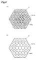
- Figure 2(a) is a cross-sectional view of the bundle fiber; and Figure 2(b) illustrates grouping of optical fibers.
- the bundle fiber 17 has a hexagonal cross-section.
- Seven optical fibers (first light guides) 18 are provided in the central portion of the bundle fiber 17.
- Thirty optical fibers (second light guides) 19 are disposed surrounding the optical fibers 18.
- the seven optical fibers 18 function as the optical fibers 6 that conduct the processing light.
- the thirty optical fibers 19 function as the optical fibers 12 that conduct the observation light.
- the thirty optical fibers 19 are categorized into four groups corresponding to the four optical fibers 12.
- a first group includes eight optical fibers 19; a second group includes seven optical fibers 19; a third group includes eight optical fibers 19; and a fourth group includes seven optical fibers 19.
- the optical fibers 19 categorized into the four groups are provided, such that the observation light can be conducted toward the electronic component 2 every group.
- the optical fibers 19 categorized into the four groups receive a control signal from the control unit 31, and conduct the observation light in the order of the first, second, third, and fourth groups.
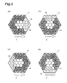
- Figures 3(a) to 3(d) illustrate a radiation timing of the observation light emitted from each group of the optical fibers.
- white circles represent a state in which the observation light emitted from the optical fibers 19 is radiated; and solid black circles represent a state in which the observation light is not radiated.
- an arrow F represents a scanning direction of the processing light.
- the optical fibers 19 of the first, second, third, and fourth groups are thus disposed the forward direction, backward direction, left hand, and right hand relative to the scanning direction F.
- the electronic component 2 is scanned and processed with the processing light conducted by the optical fibers 18, and concurrently irradiated with the observation light emitted from the optical fibers 19 of the first group alone for a predetermined period of time.
- the optical fibers 19 are categorized into the four groups, and the observation light emitted from the observation light emitting unit 4 is conducted every group to the electronic component 2.
- sequentially conducting and radiating the observation light emitted from the groups onto the electronic component 2 allows identification of an object on the electronic component 2 (a gilded terminal, a tinned terminal, and a glass epoxy substrate, for instance) which is irradiated with the observation light emitted every group.
- a position of the identified object corresponds to a disposed position of each group of the optical fibers 19.
- the position of the identified object can thus be easily determined, based on the disposed position of the group. Accordingly, it is possible to control radiation power of the processing light according to the type of the identified object, or to adjust a radiation time of the processing light according to the position of the identified object. For example, in order to bond gilded terminals with solder (tin-based) by scanning with the processing light, a boundary of the solder and the gilded terminals can be specified and the radiation power can be intensified. This can prevent the electronic component 2 from being overheated, and thus can enhance processing accuracy and quality.
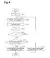
- FIG. 4 is a flowchart illustrating a control process of the laser processing apparatus according to the first embodiment. The control process in Figure 4 is repeated by the control unit 31 at a predetermined cycle.
- the group number i is first set to 1 (S11).
- light generated at the electronic component 2 by the irradiation with the observation light is detected (S13).
- the light having a plurality of wavelengths generated on the electronic component 2 is detected through the optical fibers 15 and 16 and the detecting elements 13 and 14; and an adjacent object proximate to the processed area is then identified based on properties of the detected light.
- a new group number i is set (S14).
- the group number i is compared with a reference value n (S 15). If the group number i is less than the reference value n, the process returns to S12. If the group number i is greater than the reference value n, it is determined whether or not the adjacent object is an object to be irradiated (S16).
- the optical fibers 19 are categorized into the four groups in the laser processing apparatus 1, as described above.
- the reference value n is 4, the observation light emitted from the optical fibers 19 of the first, second, third, and fourth groups is radiated in sequence.
- the control unit 31 transmits, to the processing light source 3, a control signal to reduce the irradiation power; and the processing light source 3 receives the control signal and reduces the power of the generated processing light.
- the irradiation power with the processing light is increased in a process proceeding to the next point (S18).
- the control unit 31 transmits, to the processing light source 3, a control signal to increase the irradiation power; and the processing light source 3 receives the control signal and increases the power of the generated processing light.
- the electronic component 2 is processed.
- the processes are repeated at the next point. A series of the control process ends in such a way.
- irradiation of the electronic component 2 with the observation light from each group of the optical fibers 19 enables the adjacent object in the processed area to be identified easily. It is then determined whether the adjacent object is to be irradiated. The irradiation power with the processing light is increased or reduced based on the determination. This can prevent the adjacent object from being processed by error. Consequently, the processing accuracy can be improved.
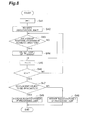
- FIG. 5 is a flowchart illustrating a control process of the laser processing apparatus according to the first embodiment.
- the control process in Figure 5 is characterized in that, among the optical fibers 19, the group disposed forward in the scanning direction of the processing light is used alone to radiate the observation light.
- the control process is repeated by the control unit 31 at a predetermined cycle.
- a new group number i is set (S25).
- the group number i is compared with a reference value n (S26). If the group number i is less than the reference value n, the process returns to S22. If the group number i is greater than the reference value n, it is determined whether or not the adjacent object is an object to be irradiated (S27).
- the control unit 31 transmits, to the processing light source 3, a control signal to reduce the irradiation power; and the processing light source 3 receives the control signal and reduces the power of the generated processing light.
- the irradiation power with the processing light is increased in a process proceeding to the next point (S29).
- the control unit 31 transmits, to the processing light source 3, a control signal to increase the irradiation power; and the processing light source 3 receives the control signal and increases the power of the generated processing light.
- the electronic component 2 is processed.
- a series of the control process ends.
- the laser processing method which identifies only the adjacent object positioned forward in the scanning direction of the processing light, contributes to an increased processing speed.
- FIG. 6 is a schematic view illustrating a configuration of the laser processing apparatus according to the second embodiment.
- the laser processing apparatus 20 according to the second embodiment is different from the first embodiment in that optical fibers (third light guides) 24 conducting light generated at the electronic component 2 are categorized into four groups.
- Other components of the configuration are equivalent to those of the laser processing apparatus 1 described above.
- the same reference numerals are assigned, and duplicated explanation is omitted to avoid redundancy.
- a detecting unit 21 has four detecting elements 23.
- the detecting elements 23 detect light having a plurality of wavelengths, including a wavelength of 445 nm and a wavelength of 660 nm.
- the four detecting elements 23 are optically connected to the four respective optical fibers 24.
- the laser processing apparatus 20 has a single observation light source (second light emitting unit) 22.
- the observation light source 22 includes a halogen lamp emitting white light.
- the observation light emitted from the observation light source 22 is radiated onto the electronic component 2 through an optical fiber 25 (second light guide).
- the optical fibers 6 and the optical fibers 24 are bundled at the emission end of the optical fibers 6 into a bundle fiber 30.
- the bundle fiber 30 has a configuration similar to the bundle fiber 17 of the first embodiment.
- the optical fibers 24 conducting light generated at the electronic component 2 are categorized into four groups; and disposed the forward direction, backward direction, left hand, and right hand relative to the scanning direction of the processing light, such that the optical fibers 24 surround the optical fibers 6 conducting the processing light.
- a collecting lens (not shown in the drawing) be installed at an end of the bundle fiber. This ensures a long operating distance to the object to be processed and facilitates operation of the apparatus.
- the optical fibers 24 categorized into the four groups are provided, such that the light having a plurality of wavelengths generated at the electronic component 2 can be conducted in sequence.
- an openable/closable mask corresponding to each group is provided between the optical fibers 24 categorized into the four groups and the detecting elements 23. Opening or closing the mask allows the light conducted by the optical fibers 24 to enter the detecting elements 23 or blocks the light in sequence.
- the optical fibers 24 are categorized into the four groups, and the light having a plurality of wavelengths generated at the electronic element 2 is conducted every group.
- differentiating a timing to conduct the light by each group allows identification of an object corresponding to the optical fibers 24 of each group (a gilded terminal, a tinned terminal, and a glass epoxy substrate, for instance).
- a position of the identified object corresponds to a disposed position of each group of the optical fibers 24.
- the position of the identified object can thus be easily determined, based on the disposed position of the group. Accordingly, it is possible to control radiation power of the processing light according to the type of the identified object, or to adjust a radiation time of the processing light according to the position of the identified object. For example, in order to bond gilded terminals with solder (tin-based) by scanning with the processing light, a boundary of the solder and the gilded terminals can be specified and the radiation power can be intensified. This can prevent the electronic component 2 from being overheated, and thus can enhance processing accuracy and quality.
- FIG. 7 is a flowchart illustrating a control process of the laser processing apparatus according to the second embodiment. The control process in Figure 7 is repeated by the control unit 31 at a predetermined cycle.
- the group number i is first set to 1 (S31).
- the observation light emitted from the optical fiber 25 is radiated onto the electronic component 2 (S32).
- light generated at the electronic component 2 by the irradiation with the observation light is detected (S33).
- a new group number i is set (S34).
- the group number i is compared with a reference value n (S35). If the group number i is less than the reference value n, the process returns to S32. If the group number i is greater than the reference value n, it is determined whether or not the adjacent object is an object to be irradiated (S36).
- the optical fibers 24 are categorized into the four groups in the laser processing apparatus 20.
- n 4
- the light through the optical fibers 24 of the first, second, third, and fourth groups is detected in sequence.
- the control unit 31 transmits, to the processing light source 3, a control signal to reduce the irradiation power; and the processing light source 3 receives the control signal and reduces the power of the generated processing light.
- the irradiation power with the processing light is increased in a process proceeding to the next point (S38).
- the control unit 31 transmits, to the processing light source 3, a control signal to increase the irradiation power; and the processing light source 3 receives the control signal and increases the power of the generated processing light.
- the electronic component 2 is processed.
- the processes are repeated at the next point. A series of the control process ends in such a way.
- detecting the light generated at the electronic component 2 through each group of the optical fibers 24 enables the adjacent object in the processed area to be identified easily. It is then determined whether the adjacent object is to be irradiated. The irradiation power with the processing light is increased or reduced based on the determination. This can prevent the adjacent object from being processed by error. Consequently, the processing accuracy can be improved.
- Figure 8 is a flowchart illustrating a control process of the laser processing apparatus according to the second embodiment.
- the control process in Figure 8 is characterized in that the light generated at the electronic component 2 is detected through the group of the optical fibers 24 disposed forward in the scanning direction of the processing light alone.
- the control process is repeated by the control unit 31 at a predetermined cycle.
- the group number i is first set to 1 (S41).
- a new group number i is set (S45).
- the group number i is compared with a reference value n (S46). If the group number i is less than the reference value n, the process returns to S43. If the group number i is greater than the reference value n, it is determined whether or not the adjacent object is an object to be irradiated (S47).
- the control unit 31 transmits, to the processing light source 3, a control signal to reduce the irradiation power; and the processing light source 3 receives the control signal and reduces the power of the generated processing light.
- the irradiation power with the processing light is increased in a process proceeding to the next point (S49).
- the control unit 31 transmits, to the processing light source 3, a control signal to increase the irradiation power; and the processing light source 3 receives the control signal and increases the power of the generated processing light.
- the electronic component 2 is processed.
- a series of the control process ends.
- the laser processing method which identifies only the adjacent object positioned forward in the scanning direction of the processing light, contributes to an increased processing speed.
- FIG. 9 is a schematic view illustrating a modification of the laser processing apparatus according to the second embodiment.
- a detecting unit 27 of a laser processing apparatus 26 includes a single detecting element 28 and a mirror 29 switching a light path (light path changing means), such that light conducted by the optical fibers 24 enters the detecting element 28.
- the turnable mirror 29 allows the light conducted by the optical fibers 24 of the four groups to enter the detecting element 28 in sequence.
- the detecting element 28 can detect light having a plurality of wavelengths, including a wavelength of 445 nm and a wavelength of 660 nm.
- the laser processing apparatus 26 having such a configuration provides effects similar to the laser processing apparatus 20 of the second embodiment.
- the configuration of the detecting unit 27 can be simplified, thus leading to cost reduction of the apparatus as a whole.
- the processing light and the observation light may have the same wavelength.
- the laser processing apparatus and the laser processing method are explained in cases where they are applied in processing of electronic components.
- the laser processing apparatus and the processing method according to the present invention are also applicable to dental therapy and others.
Landscapes
- Physics & Mathematics (AREA)
- Optics & Photonics (AREA)
- General Physics & Mathematics (AREA)
- Engineering & Computer Science (AREA)
- General Health & Medical Sciences (AREA)
- Chemical & Material Sciences (AREA)
- Analytical Chemistry (AREA)
- Biochemistry (AREA)
- Life Sciences & Earth Sciences (AREA)
- Immunology (AREA)
- Pathology (AREA)
- Health & Medical Sciences (AREA)
- Plasma & Fusion (AREA)
- Mechanical Engineering (AREA)
- Laser Beam Processing (AREA)
- Electric Connection Of Electric Components To Printed Circuits (AREA)
Abstract
Description
- The present invention relates to a laser processing apparatus and a processing method employed therein.
- An example of conventional technology in the field is disclosed in
Patent Literature 1. A laser processing apparatus disclosed in the literature has a laser light source emitting bonding light to a bonding portion of a lead and a bonding land of a substrate; another laser light source emitting determining light; a determination apparatus determining the bonding state of the bonding portion; and a CCD camera identifying a defect of the lead. The bonding portion is irradiated with the bonding light, and then irradiated with the determining light. Reflected light and radiant light from the determining light are received at the determination apparatus, which then determines the bonding state. Furthermore, the CCD camera identifies a defective lead, thus enhancing the reliability of mounting. -
- Patent Literature 1: Javanese Unexamined Patent Application Publication No.
5-335735 - The conventional laser processing apparatus, however, is not provided with a means identifying an adjacent object disposed in the vicinity of the bonding portion, a means controlling irradiation power with the bonding light according to the type of the adjacent object, for example. Such an apparatus may erroneously process the adjacent object, failing to improve processing accuracy.
- An object of the present invention is to provide a laser processing apparatus and a laser processing method having high processing accuracy.
- The present invention provides a laser processing apparatus scanning and processing an object to be processed with processing light. The laser processing apparatus includes a first light emitting unit emitting processing light; a first light guide conducting the processing light emitted from the first light emitting unit to an object to be processed; a second light emitting unit emitting observation light that observes the object to be processed; a plurality of second light guides conducting the observation light emitted from the second light emitting unit to the object to be processed; a third light guide conducting light having a plurality of wavelengths generated at the object to be processed; a detecting unit detecting the light having a plurality of wavelengths conducted by the third light guide; and a control unit controlling a light emitting state of the first light emitting unit, based on a result of detection by the detecting unit. The second light guides are categorized into at least two groups, and conduct the observation light to the object to be processed every group, the observation light being emitted from the second light emitting unit.
- According to the laser processing apparatus of the present invention, the second light guides are categorized into at least two groups, and conduct the observation light to the object to be processed every group, the observation light being emitted from the second light emitting unit. Thus, differentiating a radiation timing of the observation light emitted from each group allows identification of an object to be irradiated respectively with the observation light emitted every group. In addition, a position of the identified object corresponds to a disposed position of each group. The position of the identified object can thus be easily determined, based on the disposed position of the group. Accordingly, it is possible to control radiation power of the processing light according to the type of the identified object, or to adjust a radiation time of the processing light according to the position of the identified object. This can prevent the identified object from being processed erroneously, and thus can enhance processing accuracy.
- It is preferred in the laser processing apparatus according to the present invention that the second light guides are categorized into four groups; and that, at an emission end of the first light guide, the second light guides categorized into the four groups are disposed a forward direction, a backward direction, left hand, and right hand relative to a scanning direction of the processing light emitted from the first light guide, such that the second light guides surround the first light guide. Thereby, objects disposed in the forward direction, backward direction, left hand, and right hand to the processed area can be identified respectively.
- It is preferred in the laser processing apparatus according to the present invention that the second light guides categorized into the four groups, in sequence, conduct the observation light emitted from the second light emitting unit to the object to be processed. Thereby, an object disposed in the forward direction, backward direction, left hand, and right hand to the processed area can easily be identified.
- The present invention provides a laser processing apparatus scanning and processing an object to be processed with processing light. The laser processing apparatus includes a first light emitting unit emitting processing light; a first light guide conducting the processing light emitted from the first light emitting unit to an object to be processed; a second light emitting unit emitting observation light that observes the object to be processed; a second light guide conducting the observation light emitted from the second light emitting unit to the object to be processed; a plurality of third light guides conducting light having a plurality of wavelengths generated at the object to be processed; a detecting unit detecting the light having a plurality of wavelengths conducted by the third light guides; and a control unit controlling a light emitting state of the first light emitting unit, based on a result of detection by the detecting unit. The third light guides are categorized into at least two groups, and conduct the light every group, the light having a plurality of wavelengths generated at the object to be processed.
- According to the laser processing apparatus of the present invention, the third light guides are categorized into at least two groups, and conduct the light every group, the light having a plurality of wavelengths generated at the object to be processed. Thus, differentiating a timing to conduct the light by each group allows identification of an object corresponding to the third light guides of each group respectively. In addition, a position of the identified object corresponds to a disposed position of each group. The position of the identified object can thus be easily determined, based on the disposed position of the group. Accordingly, it is possible to control radiation power of the processing light according to the type of the identified object, or to adjust a radiation time of the processing light according to the position of the identified object. This can prevent the identified object from being processed erroneously, and thus can enhance processing accuracy.
- It is preferred in the laser processing apparatus according to the present invention that the third light guides are categorized into four groups; and that, at an emission end of the first light guide, the third light guides categorized into the four groups are disposed a forward direction, a backward direction, left hand, and right hand relative to a scanning direction of the processing light emitted from the first light guide, such that the third light guides surround the first light guide. Thereby, objects disposed in the forward direction, backward direction, left hand, and right hand to the processed area can be identified respectively.
- It is preferred in the laser processing apparatus according to the present invention that the third light guides categorized into the four groups, in sequence, conduct the light having a plurality of wavelengths generated at the object to be processed. Thereby, an object disposed over the forward direction, backward direction, left hand, and right hand to the processed area can easily be identified.
- It is preferred in the laser processing apparatus according to the present invention that the detecting unit includes a detecting element corresponding to each group of the third light guides. This enhances accuracy of the light detection.
- It is preferred in the laser processing apparatus according to the present invention that the detecting unit includes a single detecting element and light path changing means allowing the light conducted by the third light guides to enter the detecting element. This can simplify a configuration of the detecting unit, and thus can reduce cost of the apparatus as a whole.
- The present invention provides a laser processing method using the laser processing apparatus described above. The laser processing method includes (1) irradiating the object to be processed with the observation light from every group of the second light guides; (2) detecting the light having a plurality of wavelengths generated at the object to be processed, and identifying the object as an object to be irradiated or not, based on properties of the detected light; and (3) controlling the processing light based on a result of identification of the object to be irradiated, and processing the object.
- According to the laser processing method of the present invention, the object to be processed is irradiated with the observation light from every group of the second light guides, and thereby the type and position of the object disposed in the vicinity of the processed area can easily be specified. It is then possible to control radiation power of the processing light according to the type of the identified object, or to adjust a radiation time of the processing light according to the position of the identified object. This can prevent the identified object from being processed erroneously, and thus can enhance processing accuracy.
- It is preferred in the laser processing method according to the present invention that, in step (1), the group of the second light guides disposed forward in the scanning direction of the processing light is used alone to radiate the observation light onto the object to be processed. This identifies an object disposed forward in the scanning direction of the processing light alone, and thus can contribute to an increased processing speed.
- The present invention provides a laser processing method using the laser processing apparatus described above. The laser processing method includes (1) irradiating the object to be processed with the observation light; (2) detecting the light having a plurality of wavelengths generated at the object to be processed, using each group of the third light guides, and identifying the object as an object to be irradiated or not, based on properties of the detected light; and (3) controlling the processing light based on a result of identification of the object to be irradiated, and processing the object.
- According to the laser processing method of the present invention, the light having a plurality of wavelengths generated at the object to be processed is detected by each group of the third light guides, and thereby the type and position of the object disposed in the vicinity of the processed area can easily be specified. It is then possible to control radiation power of the processing light according to the type of the identified object, or to adjust a radiation time of the processing light according to the position of the identified object. This can prevent the identified object from being processed erroneously, and thus can enhance processing accuracy.
- It is preferred in the laser processing method according to the present invention that, in step (2), the group of the third light guides disposed forward in the scanning direction of the processing light is used alone to detect the light having a plurality of wavelengths generated at the object to be processed. This identifies an object disposed forward in the scanning direction of the processing light alone, and thus can contribute to an increased processing speed.
- The present invention provides the laser processing apparatus and the laser processing method capable of enhancing processing accuracy.
-
-
Figure 1 is a schematic view illustrating a configuration of a laser processing apparatus according to a first embodiment; -
Figure 2(a) is a cross-sectional view of a bundle fiber; -
Figure 2(b) illustrates grouping of optical fibers; -
Figures 3(a) to 3(d) illustrate a radiation timing of observation light emitted from each group of the optical fibers; -
Figure 4 is a flowchart illustrating a control process of the laser processing apparatus according to the first embodiment; -
Figure 5 is a flowchart illustrating a control process of the laser processing apparatus according to the first embodiment; -
Figure 6 is a schematic view illustrating a configuration of a laser processing apparatus according to a second embodiment; -
Figure 7 is a flowchart illustrating a control process of the laser processing apparatus according to the second embodiment; -
Figure 8 is a flowchart illustrating a control process of the laser processing apparatus according to the second embodiment; and -
Figure 9 is a schematic view illustrating a modification of the laser processing apparatus according to the second embodiment. - Preferred embodiments to implement the present invention are explained in detail below, with reference to the attached drawings. In the explanation of the drawings, the same reference numerals are assigned to the same elements, and duplicated explanation is omitted to avoid redundancy.
-
Figure 1 is a schematic view illustrating a configuration of a laser processing apparatus according to a first embodiment. Alaser processing apparatus 1, which is used for processing electronic components, has a processing light source (first light emitting unit) 3 emitting processing light to process an electronic component (object to be processed) 2; an observation light emitting unit (second light emitting unit) 4 emitting observation light to observe theelectronic component 2; a detectingunit 5 detecting light having a plurality of wavelengths generated at theelectronic component 2; and acontrol unit 31 controlling a light emitting state of theprocessing light source 3. - The
processing light source 3 includes a semiconductor laser element outputting laser light having a specific wavelength of 408 nm. The processing light emitted from theprocessing light source 3 is conducted to theelectronic component 2 by an optical fiber (first light guide) 6 optically connected to theprocessing light source 3. - The observation
light emitting unit 4, which emits the observation light to observe theelectronic component 2, has two types of light sources having different central wavelengths. Specifically, the observationlight emitting unit 4 includes four firstobservation light sources 7 outputting laser light having a wavelength of 445 nm, and four secondobservation light sources 8 outputting laser light having a wavelength of 660 nm. The four firstobservation light sources 7 are optically connected to four optical fibers (second light guides) 9; and the four secondobservation light sources 8 are optically connected to four optical fibers (second light guides) 10. - The
optical fibers multiplexing unit 11. The multiplexingunit 11 multiplexes the light having a wavelength of 445 nm conducted by theoptical fibers 9 and the light having a wavelength of 660 nm conducted by theoptical fibers 10 at a ratio of one to one, and then outputs the multiplexed light to theelectronic component 2 by way of four optical fibers (second light guides) 12. - The detecting
unit 5 is provided with a first detectingelement 13 and a second detectingelement 14, which have different light-receiving sensitivities depending on the wavelength. The first detectingelement 13 has a high light-receiving sensitivity to light having a wavelength of 445 nm; and the second detectingelement 14 has a high light-receiving sensitivity to light having a wavelength of 660 nm. The first detectingelement 13 and the second detectingelement 14 are optically connected to optical fibers (third light guides) 15 and 16, respectively. The first detectingelement 13 and the second detectingelement 14 detect the intensity of different wavelengths of light conducted by theoptical fibers control unit 31. The detectingunit 5 may be provided with an optical filter and a plurality of detecting elements, the optical filter transmitting or reflecting light having different center wavelengths, the detecting elements detecting the intensity of the light which has been transmitted or reflected by the optical filter and has different center wavelengths. Alternatively, the detectingunit 5 may be provided with a light path changing means and detecting elements, the light path changing means separating or switching the light path from the third light guide to the detecting element according to the wavelength, the detecting elements corresponding to light travelling through the respective light paths. - The
control unit 31 controls the light emitting state of theprocessing light source 3, based on the results detected by the first detectingelement 13 and the second detectingelement 14. Furthermore, thecontrol unit 31 calculates the ratio of the light intensity of a wavelength of 445 nm detected by the first detectingelement 13 and the light intensity of a wavelength of 660 nm detected by the second detectingelement 14. Thecontrol unit 31 then compares the computed value with a reference threshold value, and thereby identifies an object on theelectronic component 2. - The
optical fibers 6 and theoptical fibers 12 are bundled at the emission end of theoptical fibers 6 into abundle fiber 17. Bundling theoptical fibers laser processing apparatus 1 and easy operation of the apparatus. It is also preferred that a collecting lens (not shown in the drawing) be installed at an end of the bundle fiber. This ensures a long operating distance to the object to be processed and facilitates operation of the apparatus. -
Figure 2(a) is a cross-sectional view of the bundle fiber; andFigure 2(b) illustrates grouping of optical fibers. As shown inFigure 2(a) , thebundle fiber 17 has a hexagonal cross-section. Seven optical fibers (first light guides) 18 are provided in the central portion of thebundle fiber 17. Thirty optical fibers (second light guides) 19 are disposed surrounding theoptical fibers 18. The sevenoptical fibers 18 function as theoptical fibers 6 that conduct the processing light. The thirtyoptical fibers 19 function as theoptical fibers 12 that conduct the observation light. - As shown in
Figure 2(b) , the thirtyoptical fibers 19 are categorized into four groups corresponding to the fouroptical fibers 12. A first group includes eightoptical fibers 19; a second group includes sevenoptical fibers 19; a third group includes eightoptical fibers 19; and a fourth group includes sevenoptical fibers 19. - The
optical fibers 19 categorized into the four groups are provided, such that the observation light can be conducted toward theelectronic component 2 every group. For instance, theoptical fibers 19 categorized into the four groups receive a control signal from thecontrol unit 31, and conduct the observation light in the order of the first, second, third, and fourth groups.Figures 3(a) to 3(d) illustrate a radiation timing of the observation light emitted from each group of the optical fibers. InFigures 3(a) to 3(d) , white circles represent a state in which the observation light emitted from theoptical fibers 19 is radiated; and solid black circles represent a state in which the observation light is not radiated. - In
Figures 3(a) to 3(d) , an arrow F represents a scanning direction of the processing light. Theoptical fibers 19 of the first, second, third, and fourth groups are thus disposed the forward direction, backward direction, left hand, and right hand relative to the scanning direction F. As shown inFigure 3(a) , theelectronic component 2 is scanned and processed with the processing light conducted by theoptical fibers 18, and concurrently irradiated with the observation light emitted from theoptical fibers 19 of the first group alone for a predetermined period of time. Then, the irradiation with the observation light emitted from theoptical fibers 19 of the first group is stopped, and the observation light emitted from theoptical fibers 19 of the second group alone is radiated onto theelectronic component 2 for a predetermined period of time (refer toFigure 3(b) ). - Subsequently, the irradiation with the observation light emitted from the
optical fibers 19 of the second group is stopped, and the observation light emitted from theoptical fibers 19 of the third group alone is radiated onto theelectronic component 2 for a predetermined period of time (refer toFigure 3(c) ). Then, the irradiation with the observation light emitted from theoptical fibers 19 of the third group is stopped, and the observation light emitted from theoptical fibers 19 of the fourth group alone is radiated onto theelectronic component 2 for a predetermined period of time (refer toFigure 3(d) ). These operations are repeated until the processing ends. - In the laser processing apparatus having such a configuration, the
optical fibers 19 are categorized into the four groups, and the observation light emitted from the observationlight emitting unit 4 is conducted every group to theelectronic component 2. Thus, sequentially conducting and radiating the observation light emitted from the groups onto theelectronic component 2 allows identification of an object on the electronic component 2 (a gilded terminal, a tinned terminal, and a glass epoxy substrate, for instance) which is irradiated with the observation light emitted every group. - In addition, a position of the identified object corresponds to a disposed position of each group of the
optical fibers 19. The position of the identified object can thus be easily determined, based on the disposed position of the group. Accordingly, it is possible to control radiation power of the processing light according to the type of the identified object, or to adjust a radiation time of the processing light according to the position of the identified object. For example, in order to bond gilded terminals with solder (tin-based) by scanning with the processing light, a boundary of the solder and the gilded terminals can be specified and the radiation power can be intensified. This can prevent theelectronic component 2 from being overheated, and thus can enhance processing accuracy and quality. - A laser processing method using the
laser processing apparatus 1 according to the first embodiment is explained below, with reference toFigure 4. Figure 4 is a flowchart illustrating a control process of the laser processing apparatus according to the first embodiment. The control process inFigure 4 is repeated by thecontrol unit 31 at a predetermined cycle. - The group number i is first set to 1 (S11). The observation light emitted from the
optical fibers 19 of the ith (i = 1) group is radiated onto the electronic component 2 (S12). Then, light generated at theelectronic component 2 by the irradiation with the observation light is detected (S13). In the process, the light having a plurality of wavelengths generated on theelectronic component 2 is detected through theoptical fibers elements - Subsequently, 1 is added to the original group number i, and a new group number i is set (S14). The group number i is compared with a reference value n (S 15). If the group number i is less than the reference value n, the process returns to S12. If the group number i is greater than the reference value n, it is determined whether or not the adjacent object is an object to be irradiated (S16).
- The
optical fibers 19 are categorized into the four groups in thelaser processing apparatus 1, as described above. Thus, in the case where the reference value n is 4, the observation light emitted from theoptical fibers 19 of the first, second, third, and fourth groups is radiated in sequence. - If it is determined in S16 that the adjacent object is not to be irradiated, the irradiation power with the processing light is reduced in a process proceeding to the next point (S17). In the process, the
control unit 31 transmits, to theprocessing light source 3, a control signal to reduce the irradiation power; and theprocessing light source 3 receives the control signal and reduces the power of the generated processing light. - If it is determined that the adjacent object is to be irradiated, the irradiation power with the processing light is increased in a process proceeding to the next point (S18). In the process, the
control unit 31 transmits, to theprocessing light source 3, a control signal to increase the irradiation power; and theprocessing light source 3 receives the control signal and increases the power of the generated processing light. Thereby, theelectronic component 2 is processed. After the process ofS 17 orS 18 is completed, the processes are repeated at the next point. A series of the control process ends in such a way. - According to such a laser processing method, irradiation of the
electronic component 2 with the observation light from each group of theoptical fibers 19 enables the adjacent object in the processed area to be identified easily. It is then determined whether the adjacent object is to be irradiated. The irradiation power with the processing light is increased or reduced based on the determination. This can prevent the adjacent object from being processed by error. Consequently, the processing accuracy can be improved. - An alternative processing method using the
laser processing apparatus 1 is explained below with reference toFigure 5. Figure 5 is a flowchart illustrating a control process of the laser processing apparatus according to the first embodiment. The control process inFigure 5 is characterized in that, among theoptical fibers 19, the group disposed forward in the scanning direction of the processing light is used alone to radiate the observation light. The control process is repeated by thecontrol unit 31 at a predetermined cycle. - The group number i is first set to 1 (S21). It is then determined whether or not the ith (i = 1) group is positioned forward in the scanning direction of the processing light (S22). If it is determined that the group is not positioned forward in the scanning direction, the observation light emitted from the
optical fibers 19 of the group is not radiated, and the process proceeds to S25. If it is determined that the group is positioned forward in the scanning direction, the observation light emitted from theoptical fibers 19 of the group is radiated (S23). - Then, light generated at the
electronic component 2 by the irradiation with the observation light is detected (S24). In the process, the light having a plurality of wavelengths generated at theelectronic component 2 is detected through theoptical fibers elements - Subsequently, 1 is added to the original group number i, and thus a new group number i is set (S25). The group number i is compared with a reference value n (S26). If the group number i is less than the reference value n, the process returns to S22. If the group number i is greater than the reference value n, it is determined whether or not the adjacent object is an object to be irradiated (S27).
- If it is determined in S27 that the adjacent object is not to be irradiated, the irradiation power with the processing light is reduced in a process proceeding to the next point (S28). In the process, the
control unit 31 transmits, to theprocessing light source 3, a control signal to reduce the irradiation power; and theprocessing light source 3 receives the control signal and reduces the power of the generated processing light. - If it is determined that the adjacent object is to be irradiated, the irradiation power with the processing light is increased in a process proceeding to the next point (S29). In the process, the
control unit 31 transmits, to theprocessing light source 3, a control signal to increase the irradiation power; and theprocessing light source 3 receives the control signal and increases the power of the generated processing light. Thereby, theelectronic component 2 is processed. After the process of S28 or S29 is completed, a series of the control process ends. The laser processing method, which identifies only the adjacent object positioned forward in the scanning direction of the processing light, contributes to an increased processing speed. - A
laser processing apparatus 20 according to a second embodiment is explained below.Figure 6 is a schematic view illustrating a configuration of the laser processing apparatus according to the second embodiment. Thelaser processing apparatus 20 according to the second embodiment is different from the first embodiment in that optical fibers (third light guides) 24 conducting light generated at theelectronic component 2 are categorized into four groups. Other components of the configuration are equivalent to those of thelaser processing apparatus 1 described above. Thus, the same reference numerals are assigned, and duplicated explanation is omitted to avoid redundancy. - As shown in
Figure 6 , a detectingunit 21 has four detectingelements 23. The detectingelements 23 detect light having a plurality of wavelengths, including a wavelength of 445 nm and a wavelength of 660 nm. The four detectingelements 23 are optically connected to the four respectiveoptical fibers 24. Furthermore, thelaser processing apparatus 20 has a single observation light source (second light emitting unit) 22. The observationlight source 22 includes a halogen lamp emitting white light. The observation light emitted from the observationlight source 22 is radiated onto theelectronic component 2 through an optical fiber 25 (second light guide). - The
optical fibers 6 and theoptical fibers 24 are bundled at the emission end of theoptical fibers 6 into abundle fiber 30. Thebundle fiber 30 has a configuration similar to thebundle fiber 17 of the first embodiment. Specifically, theoptical fibers 24 conducting light generated at theelectronic component 2 are categorized into four groups; and disposed the forward direction, backward direction, left hand, and right hand relative to the scanning direction of the processing light, such that theoptical fibers 24 surround theoptical fibers 6 conducting the processing light. It is also preferred that a collecting lens (not shown in the drawing) be installed at an end of the bundle fiber. This ensures a long operating distance to the object to be processed and facilitates operation of the apparatus. - The
optical fibers 24 categorized into the four groups are provided, such that the light having a plurality of wavelengths generated at theelectronic component 2 can be conducted in sequence. For instance, an openable/closable mask corresponding to each group is provided between theoptical fibers 24 categorized into the four groups and the detectingelements 23. Opening or closing the mask allows the light conducted by theoptical fibers 24 to enter the detectingelements 23 or blocks the light in sequence. - In the
laser processing apparatus 20 having such a configuration, theoptical fibers 24 are categorized into the four groups, and the light having a plurality of wavelengths generated at theelectronic element 2 is conducted every group. Thus, differentiating a timing to conduct the light by each group allows identification of an object corresponding to theoptical fibers 24 of each group (a gilded terminal, a tinned terminal, and a glass epoxy substrate, for instance). - In addition, a position of the identified object corresponds to a disposed position of each group of the
optical fibers 24. The position of the identified object can thus be easily determined, based on the disposed position of the group. Accordingly, it is possible to control radiation power of the processing light according to the type of the identified object, or to adjust a radiation time of the processing light according to the position of the identified object. For example, in order to bond gilded terminals with solder (tin-based) by scanning with the processing light, a boundary of the solder and the gilded terminals can be specified and the radiation power can be intensified. This can prevent theelectronic component 2 from being overheated, and thus can enhance processing accuracy and quality. - A laser processing method using the
laser processing apparatus 20 according to the second embodiment is explained below, with reference toFigure 7. Figure 7 is a flowchart illustrating a control process of the laser processing apparatus according to the second embodiment. The control process inFigure 7 is repeated by thecontrol unit 31 at a predetermined cycle. - The group number i is first set to 1 (S31). The observation light emitted from the
optical fiber 25 is radiated onto the electronic component 2 (S32). Then, light generated at theelectronic component 2 by the irradiation with the observation light is detected (S33). In the process, the light having a plurality of wavelengths generated on theelectronic component 2 is detected through theoptical fibers 24 of the ith (i = 1) group and the detectingelement 23 thereof; and an adjacent object proximate to the processed area is then identified based on properties of the detected light. - Subsequently, 1 is added to the original group number i, and a new group number i is set (S34). The group number i is compared with a reference value n (S35). If the group number i is less than the reference value n, the process returns to S32. If the group number i is greater than the reference value n, it is determined whether or not the adjacent object is an object to be irradiated (S36).
- The
optical fibers 24 are categorized into the four groups in thelaser processing apparatus 20. Thus, at a reference value n of 4, for example, the light through theoptical fibers 24 of the first, second, third, and fourth groups is detected in sequence. - If it is determined in S36 that the adjacent object is not to be irradiated, the irradiation power with the processing light is reduced in a process proceeding to the next point (S37). In the process, the
control unit 31 transmits, to theprocessing light source 3, a control signal to reduce the irradiation power; and theprocessing light source 3 receives the control signal and reduces the power of the generated processing light. - If it is determined that the adjacent object is to be irradiated, the irradiation power with the processing light is increased in a process proceeding to the next point (S38). In the process, the
control unit 31 transmits, to theprocessing light source 3, a control signal to increase the irradiation power; and theprocessing light source 3 receives the control signal and increases the power of the generated processing light. Thereby, theelectronic component 2 is processed. After the process of S37 or S38 is completed, the processes are repeated at the next point. A series of the control process ends in such a way. - According to such a laser processing method, detecting the light generated at the
electronic component 2 through each group of theoptical fibers 24 enables the adjacent object in the processed area to be identified easily. It is then determined whether the adjacent object is to be irradiated. The irradiation power with the processing light is increased or reduced based on the determination. This can prevent the adjacent object from being processed by error. Consequently, the processing accuracy can be improved. - An alternative processing method using the
laser processing apparatus 20 is explained below with reference toFigure 8. Figure 8 is a flowchart illustrating a control process of the laser processing apparatus according to the second embodiment. The control process inFigure 8 is characterized in that the light generated at theelectronic component 2 is detected through the group of theoptical fibers 24 disposed forward in the scanning direction of the processing light alone. The control process is repeated by thecontrol unit 31 at a predetermined cycle. - The group number i is first set to 1 (S41). The observation light emitted from the
optical fiber 25 is radiated onto the electronic component 2 (S42). It is then determined whether or not the ith (i = 1) group is positioned forward in the scanning direction of the processing light (S43). If it is determined that the ith group is not positioned forward in the scanning direction, the light through theoptical fibers 24 of the group is not detected, and the process proceeds to S45. If it is determined that the ith group is positioned forward in the scanning direction, the light generated at theelectronic component 2 and passing through theoptical fibers 24 of the group is detected (S44). Then, an adjacent object is identified based on properties of the detected light. - Subsequently, 1 is added to the original group number i, and thus a new group number i is set (S45). The group number i is compared with a reference value n (S46). If the group number i is less than the reference value n, the process returns to S43. If the group number i is greater than the reference value n, it is determined whether or not the adjacent object is an object to be irradiated (S47).
- If it is determined in S47 that the adjacent object is not to be irradiated, the irradiation power with the processing light is reduced in a process proceeding to the next point (S48). In the process, the
control unit 31 transmits, to theprocessing light source 3, a control signal to reduce the irradiation power; and theprocessing light source 3 receives the control signal and reduces the power of the generated processing light. - If it is determined that the adjacent object is to be irradiated, the irradiation power with the processing light is increased in a process proceeding to the next point (S49). In the process, the
control unit 31 transmits, to theprocessing light source 3, a control signal to increase the irradiation power; and theprocessing light source 3 receives the control signal and increases the power of the generated processing light. Thereby, theelectronic component 2 is processed. After the process of S48 or S49 is completed, a series of the control process ends. The laser processing method, which identifies only the adjacent object positioned forward in the scanning direction of the processing light, contributes to an increased processing speed. - A modification of the
laser processing apparatus 20 according to the second embodiment is explained below.Figure 9 is a schematic view illustrating a modification of the laser processing apparatus according to the second embodiment. In the modification shown inFigure 9 , a detectingunit 27 of alaser processing apparatus 26 includes a single detectingelement 28 and amirror 29 switching a light path (light path changing means), such that light conducted by theoptical fibers 24 enters the detectingelement 28. Theturnable mirror 29 allows the light conducted by theoptical fibers 24 of the four groups to enter the detectingelement 28 in sequence. The detectingelement 28 can detect light having a plurality of wavelengths, including a wavelength of 445 nm and a wavelength of 660 nm. - The
laser processing apparatus 26 having such a configuration provides effects similar to thelaser processing apparatus 20 of the second embodiment. In addition, the configuration of the detectingunit 27 can be simplified, thus leading to cost reduction of the apparatus as a whole. - The present invention is by no means limited to the embodiments above. For example, the processing light and the observation light may have the same wavelength. In the embodiments above, the laser processing apparatus and the laser processing method are explained in cases where they are applied in processing of electronic components. In addition to processing of electronic components, the laser processing apparatus and the processing method according to the present invention are also applicable to dental therapy and others.
-
- 1, 20, 26 Laser processing apparatus
- 2 Electronic component (object to be processed)
- 3 Processing light source (first light emitting unit)
- 4 Observation light emitting unit (second light emitting unit)
- 5,21,27 Detecting unit
- 6, 18 Optical fiber (first light guide)
- 9, 10, 12, 19, 25 Optical fiber (second light guide)
- 15, 16, 24 Optical fiber (third light guide)
- 22 Observation light source (second light emitting unit)
- 29 Mirror (light path changing means)
- 31 Control unit
Claims (12)
- A laser processing apparatus scanning and processing an object to be processed with processing light, the laser processing apparatus comprising:a first light emitting unit emitting processing light;a first light guide conducting the processing light emitted from the first light emitting unit to an object to be processed;a second light emitting unit emitting observation light that observes the object to be processed;a plurality of second light guides conducting the observation light emitted from the second light emitting unit to the object to be processed;a third light guide conducting light having a plurality of wavelengths generated at the object to be processed;a detecting unit detecting the light having a plurality of wavelengths conducted by the third light guide; anda control unit controlling a light emitting state of the first light emitting unit, based on a result of detection by the detecting unit, whereinthe second light guides are categorized into at least two groups, and conduct the observation light to the object to be processed every group, the observation light being emitted from the second light emitting unit.
- The laser processing apparatus according to claim 1, wherein
the second light guides are categorized into four groups; and
at an emission end of the first light guide, the second light guides categorized into the four groups are disposed a forward direction, a backward direction, left hand, and right hand relative to a scanning direction of the processing light emitted from the first light guide, such that the second light guides surround the first light guide. - The laser processing apparatus according to claim 2, wherein the second light guides categorized into the four groups, in sequence, conduct the observation light emitted from the second light emitting unit to the object to be processed.
- A laser processing apparatus scanning and processing an object to be processed with processing light, the laser processing apparatus comprising:a first light emitting unit emitting processing light;a first light guide conducting the processing light emitted from the first light emitting unit to an object to be processed;a second light emitting unit emitting observation light that observes the object to be processed;a second light guide conducting the observation light emitted from the second light emitting unit to the object to be processed;a plurality of third light guides conducting light having a plurality of wavelengths generated at the object to be processed;a detecting unit detecting the light having a plurality of wavelengths conducted by the third light guides; anda control unit controlling a light emitting state of the first light emitting unit, based on a result of detection by the detecting unit, whereinthe third light guides are categorized into at least two groups, and conduct the light every group, the light having a plurality of wavelengths generated at the object to be processed.
- The laser processing apparatus according to claim 4, wherein
the third light guides are categorized into four groups; and
at an emission end of the first light guide, the third light guides categorized into the four groups are disposed a forward direction, a backward direction, left hand, and right hand relative to a scanning direction of the processing light emitted from the first light guide, such that the third light guides surround the first light guide. - The laser processing apparatus according to claim 5, wherein the third light guides categorized into the four groups, in sequence, conduct the light having a plurality of wavelengths generated at the object to be processed.
- The laser processing apparatus according to one of claims 4 to 6, wherein the detecting unit comprises a detecting element corresponding to each group of the third light guides.
- The laser processing apparatus according to one of claims 4 to 6, wherein the detecting unit comprises:a single detecting element; andlight path changing means allowing the light conducted by the third light guides to enter the detecting element.
- A laser processing method using the laser processing apparatus according to claim 1, the laser processing method comprising:(1) irradiating the object to be processed with the observation light from every group of the second light guides;(2) detecting the light having a plurality of wavelengths generated at the object to be processed, and identifying the object as an object to be irradiated or not, based on properties of the detected light; and(3) controlling the processing light based on a result of identification of the object to be irradiated, and processing the object.
- The laser processing method according to claim 9, wherein, in step (1), the group of the second light guides disposed forward in the scanning direction of the processing light is used alone to radiate the observation light onto the object to be processed.
- A laser processing method using the laser processing apparatus according to claim 4, the laser processing method comprising:(1) irradiating the object to be processed with the observation light;(2) detecting the light having a plurality of wavelengths generated at the object to be processed, using each group of the third light guides, and identifying the object as an object to be irradiated or not, based on properties of the detected light; and(3) controlling the processing light based on a result of identification of the object to be irradiated, and processing the object.
- The laser processing method according to claim 11, wherein, in step (2), the group of the third light guides disposed forward in the scanning direction of the processing light is used alone to detect the light having a plurality of wavelengths generated at the object to be processed.
Applications Claiming Priority (2)
| Application Number | Priority Date | Filing Date | Title |
|---|---|---|---|
| JP2008185175 | 2008-07-16 | ||
| PCT/JP2009/061110 WO2010007852A1 (en) | 2008-07-16 | 2009-06-18 | Laser processing apparatus and processing method employed therein |
Publications (2)
| Publication Number | Publication Date |
|---|---|
| EP2329907A1 true EP2329907A1 (en) | 2011-06-08 |
| EP2329907A4 EP2329907A4 (en) | 2014-01-29 |
Family
ID=41550260
Family Applications (1)
| Application Number | Title | Priority Date | Filing Date |
|---|---|---|---|
| EP09797780.5A Withdrawn EP2329907A4 (en) | 2008-07-16 | 2009-06-18 | LASER PROCESSING APPARATUS AND PROCESSING METHOD EMPLOYED THEREIN |
Country Status (5)
| Country | Link |
|---|---|
| US (1) | US8546722B2 (en) |
| EP (1) | EP2329907A4 (en) |
| JP (1) | JP5440499B2 (en) |
| CN (1) | CN102099145B (en) |
| WO (1) | WO2010007852A1 (en) |
Cited By (1)
| Publication number | Priority date | Publication date | Assignee | Title |
|---|---|---|---|---|
| EP3088123A4 (en) * | 2015-03-10 | 2017-04-19 | Technology Research Association For Future Additive Manufacturing | Optical processing head and 3-dimensional fabrication device |
Families Citing this family (3)
| Publication number | Priority date | Publication date | Assignee | Title |
|---|---|---|---|---|
| JP6832004B2 (en) * | 2017-02-21 | 2021-02-24 | 株式会社ジャパンユニックス | Manual laser welding device |
| DE102018112129A1 (en) * | 2018-05-18 | 2019-11-21 | Volkswagen Aktiengesellschaft | Method for the generative production of a component, device for carrying out the method and motor vehicle |
| JP7641528B2 (en) | 2021-05-21 | 2025-03-07 | パナソニックIpマネジメント株式会社 | Phase contrast microscope |
Family Cites Families (19)
| Publication number | Priority date | Publication date | Assignee | Title |
|---|---|---|---|---|
| US4761054A (en) * | 1984-10-04 | 1988-08-02 | Mitsubishi Denki Kabushiki Kaisha | Infrared fiber cable |
| JPS63108983A (en) * | 1986-10-27 | 1988-05-13 | Toshiba Corp | Laser beam machine |
| GB2236846B (en) * | 1988-11-22 | 1992-10-14 | Fiat Auto Spa | Laser welding monitoring systems. |
| JPH047850A (en) | 1990-04-25 | 1992-01-13 | Mitsubishi Electric Corp | Tape carrier |
| JPH047850U (en) * | 1990-05-09 | 1992-01-24 | ||
| US5071417A (en) * | 1990-06-15 | 1991-12-10 | Rare Earth Medical Lasers, Inc. | Laser fusion of biological materials |
| JPH05335735A (en) | 1992-06-03 | 1993-12-17 | Mitsubishi Electric Corp | Laser OLB device and semiconductor device mounting method |
| US5382770A (en) * | 1993-01-14 | 1995-01-17 | Reliant Laser Corporation | Mirror-based laser-processing system with visual tracking and position control of a moving laser spot |
| JP3746555B2 (en) | 1996-02-06 | 2006-02-15 | 株式会社フジクラ | Laser processing apparatus and laser processing method using the same |
| DE29705934U1 (en) * | 1997-04-03 | 1997-06-05 | Kaltenbach & Voigt Gmbh & Co, 88400 Biberach | Diagnostic and treatment device for teeth |
| JPH10314968A (en) * | 1997-05-14 | 1998-12-02 | Sumitomo Heavy Ind Ltd | Laser beam machining device |
| JP3227650B2 (en) * | 1998-07-31 | 2001-11-12 | 住友重機械工業株式会社 | Laser welding machine and laser welding condition monitoring method |
| WO2000041836A1 (en) * | 1999-01-14 | 2000-07-20 | Powerlasers Limited | Structured multi-spot detecting technique for adaptive control of laser beam processing |
| JP4045424B2 (en) * | 2002-08-02 | 2008-02-13 | トヨタ自動車株式会社 | Laser welding quality inspection method and apparatus |
| JP4054994B2 (en) * | 2003-04-25 | 2008-03-05 | トヨタ自動車株式会社 | Monitoring apparatus and monitoring method for laser welding quality evaluation |
| JP4537686B2 (en) | 2003-10-27 | 2010-09-01 | 芝浦メカトロニクス株式会社 | Laser processing equipment |
| CN101588888A (en) * | 2007-01-17 | 2009-11-25 | 住友电气工业株式会社 | Laser processing device and its processing method |
| DE102010015023B4 (en) * | 2010-04-14 | 2012-05-10 | Mel Mikroelektronik Gmbh | Method and device for quality assurance and process control in the laser machining of workpieces |
| DE202010005013U1 (en) * | 2010-04-14 | 2011-08-09 | Mel Mikroelektronik Gmbh | Device for quality assurance and process control in the laser machining of workpieces |
-
2009
- 2009-06-18 US US13/054,459 patent/US8546722B2/en not_active Expired - Fee Related
- 2009-06-18 CN CN200980127599.2A patent/CN102099145B/en not_active Expired - Fee Related
- 2009-06-18 JP JP2010520808A patent/JP5440499B2/en not_active Expired - Fee Related
- 2009-06-18 EP EP09797780.5A patent/EP2329907A4/en not_active Withdrawn
- 2009-06-18 WO PCT/JP2009/061110 patent/WO2010007852A1/en not_active Ceased
Cited By (2)
| Publication number | Priority date | Publication date | Assignee | Title |
|---|---|---|---|---|
| EP3088123A4 (en) * | 2015-03-10 | 2017-04-19 | Technology Research Association For Future Additive Manufacturing | Optical processing head and 3-dimensional fabrication device |
| US9863803B2 (en) | 2015-03-10 | 2018-01-09 | Technology Research Association For Future Additive Manufacturing | Optical processing head having a plurality of optical fibers arranged to surround the light guide and 3D shaping apparatus |
Also Published As
| Publication number | Publication date |
|---|---|
| CN102099145B (en) | 2014-08-13 |
| JP5440499B2 (en) | 2014-03-12 |
| US8546722B2 (en) | 2013-10-01 |
| WO2010007852A1 (en) | 2010-01-21 |
| CN102099145A (en) | 2011-06-15 |
| US20110155709A1 (en) | 2011-06-30 |
| EP2329907A4 (en) | 2014-01-29 |
| JPWO2010007852A1 (en) | 2012-01-05 |
Similar Documents
| Publication | Publication Date | Title |
|---|---|---|
| US20240361244A1 (en) | Inspection apparatus and inspection method | |
| JP3051207B2 (en) | Apparatus and method for inspecting documents | |
| WO2007079398A3 (en) | System and method for fiber optic bundle-based illumination for imaging system | |
| US20010031502A1 (en) | Biochip detection system | |
| CN101588888A (en) | Laser processing device and its processing method | |
| US11487093B2 (en) | Method for scanning microscopy and scanning microscope | |
| EP2329907A1 (en) | Laser processing apparatus and processing method employed therein | |
| WO1995021393A3 (en) | Process and device for optically measuring a point on a sample with high local resolution | |
| CN113424088B (en) | Optical fiber fusion splicing machine and optical fiber fusion splicing method | |
| KR102898288B1 (en) | Inspection device and inspection method | |
| CN103311800B (en) | Linear light source generating device and marketable bill detecting system | |
| CN103282759A (en) | Sensor apparatus for detecting and monitoring a crack propagating through a structure | |
| WO2016116967A1 (en) | Lighting system for endoscope | |
| KR102269706B1 (en) | Multi channel fiber photometry system using adaptive optics | |
| KR20240001353A (en) | Multispectral fluorescence imaging apparatus | |
| JP2021139887A (en) | Identification device | |
| JP4576148B2 (en) | Scanning laser microscope equipment | |
| RU2355033C1 (en) | Method of determining banknote authenticity during high-speed sorting and device for determining banknote authenticity during high-speed sorting | |
| JP2012127924A (en) | Detection device and detection method for a plurality of objects | |
| KR20230167976A (en) | Multispectral fluorescence imaging apparatus | |
| KR20260015745A (en) | Optical apparatus and control method of the same | |
| CN117825297A (en) | A sample analyzer and control method thereof | |
| CN118671739A (en) | Photoelectric detector test system and test method thereof, laser radar | |
| CN114252238A (en) | Detection equipment and its light-receiving device | |
| KR20030055564A (en) | optical wavelength measuring equipment |
Legal Events
| Date | Code | Title | Description |
|---|---|---|---|
| PUAI | Public reference made under article 153(3) epc to a published international application that has entered the european phase |
Free format text: ORIGINAL CODE: 0009012 |
|
| 17P | Request for examination filed |
Effective date: 20110208 |
|
| AK | Designated contracting states |
Kind code of ref document: A1 Designated state(s): AT BE BG CH CY CZ DE DK EE ES FI FR GB GR HR HU IE IS IT LI LT LU LV MC MK MT NL NO PL PT RO SE SI SK TR |
|
| AX | Request for extension of the european patent |
Extension state: AL BA RS |
|
| DAX | Request for extension of the european patent (deleted) | ||
| RIN1 | Information on inventor provided before grant (corrected) |
Inventor name: HASEGAWA TAKEMI Inventor name: HATAYAMA HITOSHI Inventor name: KOHDA HIROSHI Inventor name: NAKAZATO KOJI Inventor name: INOUE AKIRA Inventor name: YAMADA EIICHIRO |
|
| A4 | Supplementary search report drawn up and despatched |
Effective date: 20140108 |
|
| RIC1 | Information provided on ipc code assigned before grant |
Ipc: A61B 1/00 20060101ALI20131220BHEP Ipc: G02B 23/26 20060101ALI20131220BHEP Ipc: B23K 26/08 20060101ALI20131220BHEP Ipc: B23K 26/00 20060101AFI20131220BHEP |
|
| 17Q | First examination report despatched |
Effective date: 20160225 |
|
| STAA | Information on the status of an ep patent application or granted ep patent |
Free format text: STATUS: THE APPLICATION IS DEEMED TO BE WITHDRAWN |
|
| 18D | Application deemed to be withdrawn |
Effective date: 20160707 |