JP6832004B2 - Manual laser welding device - Google Patents
Manual laser welding device Download PDFInfo
- Publication number
- JP6832004B2 JP6832004B2 JP2017030214A JP2017030214A JP6832004B2 JP 6832004 B2 JP6832004 B2 JP 6832004B2 JP 2017030214 A JP2017030214 A JP 2017030214A JP 2017030214 A JP2017030214 A JP 2017030214A JP 6832004 B2 JP6832004 B2 JP 6832004B2
- Authority
- JP
- Japan
- Prior art keywords
- laser
- irradiation
- mode
- soldering
- module
- Prior art date
- Legal status (The legal status is an assumption and is not a legal conclusion. Google has not performed a legal analysis and makes no representation as to the accuracy of the status listed.)
- Active
Links
- 238000003466 welding Methods 0.000 title claims description 36
- 239000007789 gas Substances 0.000 claims description 33
- 239000013307 optical fiber Substances 0.000 claims description 26
- 239000000835 fiber Substances 0.000 claims description 20
- 230000003287 optical effect Effects 0.000 claims description 20
- 239000011261 inert gas Substances 0.000 claims description 19
- 238000002347 injection Methods 0.000 claims description 11
- 239000007924 injection Substances 0.000 claims description 11
- 230000001678 irradiating effect Effects 0.000 claims description 5
- 238000005476 soldering Methods 0.000 description 71
- 229910000679 solder Inorganic materials 0.000 description 18
- XEEYBQQBJWHFJM-UHFFFAOYSA-N Iron Chemical compound [Fe] XEEYBQQBJWHFJM-UHFFFAOYSA-N 0.000 description 14
- 238000012986 modification Methods 0.000 description 8
- 230000004048 modification Effects 0.000 description 8
- 229910052742 iron Inorganic materials 0.000 description 7
- 239000000057 synthetic resin Substances 0.000 description 6
- 229920003002 synthetic resin Polymers 0.000 description 6
- 229910052751 metal Inorganic materials 0.000 description 4
- 239000002184 metal Substances 0.000 description 4
- 238000001816 cooling Methods 0.000 description 3
- 238000010586 diagram Methods 0.000 description 3
- 230000017525 heat dissipation Effects 0.000 description 3
- 230000002265 prevention Effects 0.000 description 3
- XKRFYHLGVUSROY-UHFFFAOYSA-N Argon Chemical compound [Ar] XKRFYHLGVUSROY-UHFFFAOYSA-N 0.000 description 2
- ATJFFYVFTNAWJD-UHFFFAOYSA-N Tin Chemical compound [Sn] ATJFFYVFTNAWJD-UHFFFAOYSA-N 0.000 description 2
- 229910052782 aluminium Inorganic materials 0.000 description 2
- XAGFODPZIPBFFR-UHFFFAOYSA-N aluminium Chemical compound [Al] XAGFODPZIPBFFR-UHFFFAOYSA-N 0.000 description 2
- 238000000034 method Methods 0.000 description 2
- 230000003647 oxidation Effects 0.000 description 2
- 238000007254 oxidation reaction Methods 0.000 description 2
- 230000001681 protective effect Effects 0.000 description 2
- 239000004065 semiconductor Substances 0.000 description 2
- IJGRMHOSHXDMSA-UHFFFAOYSA-N Atomic nitrogen Chemical compound N#N IJGRMHOSHXDMSA-UHFFFAOYSA-N 0.000 description 1
- 229910052786 argon Inorganic materials 0.000 description 1
- 230000003247 decreasing effect Effects 0.000 description 1
- 229910001873 dinitrogen Inorganic materials 0.000 description 1
- 230000003628 erosive effect Effects 0.000 description 1
- 238000002474 experimental method Methods 0.000 description 1
- 238000003780 insertion Methods 0.000 description 1
- 230000037431 insertion Effects 0.000 description 1
- 238000007689 inspection Methods 0.000 description 1
- 239000000696 magnetic material Substances 0.000 description 1
- 238000005192 partition Methods 0.000 description 1
- 238000003825 pressing Methods 0.000 description 1
- 229920003051 synthetic elastomer Polymers 0.000 description 1
- 239000005061 synthetic rubber Substances 0.000 description 1
Images


Description
本発明は、レーザー光を照射してハンダ付けや合成樹脂の溶着等を行うレーザー溶着装置に関するものであり、更に詳しくは、片手に持って手動で溶着作業を行うことができ、極小部位の溶着にも適した、手動式のレーザー溶着装置に関するものである。 The present invention relates to a laser welding device that irradiates a laser beam to perform soldering, welding of synthetic resin, and the like. More specifically, the present invention can be held in one hand to perform manual welding, and welding of extremely small parts can be performed. It relates to a manual laser welding device which is also suitable for.
例えば、回路基板に形成された電極部に電子部品のリードを手動でハンダ付けするような場合、一般にハンダ鏝が使用される。このハンダ鏝は、特許文献1に開示されているように、片手に持つための把手の先端に鏝先を有すると共に、該鏝先を取り囲むケースの内部にヒーターを有し、該ヒーターで前記鏝先を加熱して、加熱した鏝先で前記電極部及びリードを加熱すると共に、ハンダを溶融させ、溶融したハンダで前記リードを前記電極部に接着するものである。
一方で、近年においては、前記電子部品の小形化が進み、それに伴って電極部やリード等のハンダ付け対象部位も極小化しているため、それに合わせて前記ハンダ鏝の鏝先も、小形のものが要求されるようになっている。
For example, a soldering iron is generally used when the leads of electronic components are manually soldered to an electrode portion formed on a circuit board. As disclosed in Patent Document 1, this soldering iron has a soldering tip at the tip of a handle for holding in one hand, and also has a heater inside a case surrounding the soldering tip, and the soldering iron has the heater. The tip is heated, the electrode portion and the lead are heated by the heated handle, the solder is melted, and the lead is adhered to the electrode portion by the melted solder.
On the other hand, in recent years, the miniaturization of the electronic components has progressed, and along with this, the parts to be soldered such as the electrode portion and the lead have also been minimized. Therefore, the tip of the soldering iron is also miniaturized accordingly. Is now required.
しかし、ハンダ鏝の鏝先を小形化するのは、耐久性の点で限界がある。例えば、鏝先の先端径を0.2mmに形成し、この鏝先を380度に加熱してハンダ付けした場合、ハンダの主成分である錫による浸食を受けるため、前記鏝先の寿命は僅か2時間程度になってしまうことが実験により確かめられている。このため、ハンダ鏝を使用して極小部位のハンダ付けを行うのは、実用上ほぼ不可能であった。 However, reducing the size of the tip of the soldering iron has a limit in terms of durability. For example, when the tip diameter of the trowel tip is formed to 0.2 mm and the trowel tip is heated to 380 degrees and soldered, the life of the trowel tip is short because it is eroded by tin, which is the main component of the solder. It has been confirmed by experiments that it takes about 2 hours. For this reason, it has been practically impossible to solder a very small part using a soldering iron.
一方、レーザー光を使用するレーザーハンダ付け装置も知られている。このレーザーハンダ付け装置は、特許文献2に開示されているように、レーザー光を発生させるレーザー発生装置と、集光レンズを内蔵した照射ヘッドとを、光ファイバーで接続したもので、前記レーザー発生装置で発生したレーザー光を、前記光ファイバーを通じて照射ヘッドに導き、前記集光レンズで集光してハンダ付け部位に照射し、そのエネルギーでハンダを溶融させてハンダ付けするものである。
このレーザーハンダ付け装置は、ハンダと非接触でハンダ付け部位をハンダ付けすることができるため、錫による浸食の問題がなく、しかも、レーザー光のビーム径を小さく絞ることができるので、極小部位のハンダ付けも行うことができる。
On the other hand, a laser soldering device that uses laser light is also known. As disclosed in
Since this laser soldering device can solder the soldered part without contacting the solder, there is no problem of erosion by tin, and the beam diameter of the laser light can be narrowed down to a small size, so that the soldered part can be made into a very small part. Soldering can also be done.
しかし、従来のレーザーハンダ付け装置は、前述したような装置構成であるため、全体が非常に大形であり、このため、ハンダ付けロボットに装着して使用することしかできなかった。そこで、手動でハンダ付けを行うことができる簡便で小形化されたレーザーハンダ付け装置の出現が要望されている。この問題は、合成樹脂の溶着を行う溶着装置においても同様である。 However, since the conventional laser soldering device has the device configuration as described above, the whole is very large, and therefore, it can only be used by being attached to a soldering robot. Therefore, there is a demand for the emergence of a simple and compact laser soldering device that can be manually soldered. This problem also applies to a welding device that welds a synthetic resin.
本発明の課題は、片手に持って手動で溶着作業を行うことができ、極小部位の溶着にも適した、手動式のレーザー溶着装置を提供することにある。 An object of the present invention is to provide a manual laser welding device that can be held in one hand to perform a manual welding operation and is also suitable for welding a very small portion.
前記課題を解決するため、本発明によれば、片手でペンを持つように握るためのグリップ部を有するボディに、発光素子をレーザー発振させてレーザー光を出射するレーザーモジュールと、該レーザーモジュールを制御する制御回路とが内蔵されると共に、前記レーザーモジュールから出射されたレーザー光を溶着対象部位に向けて照射するための照射部材と、前記レーザーモジュールをオン・オフ操作するための照射ボタンとが設けられ、前記照射部材は、前記ボディの先端に取り付けられたファイバーホルダーと、該ファイバーホルダーに基端部を保持されて先端部が該ファイバーホルダーからボデイの前方に向けて延出する光ファイバーとを有することを特徴とする手動式レーザー溶着装置が提供される。 In order to solve the above problems, according to the present invention, a laser module that emits laser light by oscillating a light emitting element with a laser is provided on a body having a grip portion for holding a pen with one hand, and the laser module. A control circuit for controlling is built in, and an irradiation member for irradiating the laser beam emitted from the laser module toward the welding target site and an irradiation button for turning on / off the laser module are provided. The irradiation member is provided with a fiber holder attached to the tip of the body and an optical fiber whose base end is held by the fiber holder and whose tip extends from the fiber holder toward the front of the body. A manual laser welding device characterized by having is provided.
前記ファイバーホルダーは、前記レーザーモジュールと光ファイバーとを光学的に接続するための光コネクタを兼ねており、該ファイバーホルダーを介して前記照射部材が前記ボディに着脱自在に取り付けられており、この照射部材を光ファイバーの線径が異なる他の照射部材と交換することにより、レーザー光のビーム径が変更可能である。 The fiber holder also serves as an optical connector for optically connecting the laser module and the optical fiber, and the irradiation member is detachably attached to the body via the fiber holder, and the irradiation member is detachably attached to the body. The beam diameter of the laser beam can be changed by replacing the optical fiber with another irradiation member having a different optical fiber diameter.
本発明において好ましくは、前記ボディに、前記制御回路による制御モードを、前記レーザーモジュールからレーザー光の出射が可能な照射モードとレーザー光の出射が不可能な停止モードとに切り換えるためのモード切換スイッチが設けられ、該モード切換スイッチで制御モードを前記照射モードに切り換えると前記照射ボタンの操作が有効になり、前記モード切換スイッチで制御モードを前記停止モードに切り換えると前記照射ボタンの操作が無効になるように構成されていることである。 In the present invention, preferably, a mode changeover switch for switching the control mode by the control circuit on the body between an irradiation mode in which laser light can be emitted from the laser module and a stop mode in which laser light cannot be emitted. Is provided, when the control mode is switched to the irradiation mode with the mode changeover switch, the operation of the irradiation button is enabled, and when the control mode is switched to the stop mode with the mode changeover switch, the operation of the irradiation button is invalidated. is that is configured to be.
また、本発明においては、前記レーザー光より低出力の可視光からなるガイド光を、前記レーザー光の光軸に沿って出射可能であるように構成することもできる。 Further, in the present invention, the guide light composed of visible light having a lower output than the laser light can be configured to be emitted along the optical axis of the laser light.
本発明のレーザー溶着装置は、前記ボディの内部に、ガス流路が前記レーザーモジュールと接するように形成され、該ガス流路に不活性ガスを導入するためのガス導入口が前記ボディの後端部に形成されると共に、前記ガス流路内の不活性ガスを溶着対象部位に向けて噴射するためのガス噴射口が前記ボディの先端部に形成されていても良い。
この場合、複数の前記ガス噴射口が、不活性ガスを該噴射口から前記光ファイバーの回りを取り囲んだ状態に噴射可能なるように配置されていることが望ましい。
In the laser welding device of the present invention, a gas flow path is formed inside the body so as to be in contact with the laser module, and a gas introduction port for introducing an inert gas into the gas flow path is a rear end of the body. In addition to being formed in the portion, a gas injection port for injecting the inert gas in the gas flow path toward the welding target portion may be formed in the tip portion of the body.
In this case, it is desirable that the plurality of gas injection ports are arranged so that the inert gas can be injected from the injection port so as to surround the optical fiber.
本発明のレーザー溶着装置は、片手に持つように構成したボディに、レーザーモジュールと制御回路とを内蔵すると共に、前記レーザーモジュールから出射されたレーザー光を溶着対象部位に向けて照射するための照射部材を取り付けたので、全体として小形で、片手に持って手動で溶着作業を行うことができるだけでなく、レーザー光によって極小部位の溶着を行うこともできる。 In the laser welding device of the present invention, a laser module and a control circuit are built in a body configured to be held in one hand, and irradiation for irradiating a laser beam emitted from the laser module toward a welding target portion is performed. Since the member is attached, it is small as a whole, and not only can it be held in one hand to perform the welding work manually, but it is also possible to perform welding of a very small part by laser light.
図には、本発明に係る手動式レーザー溶着装置として、その代表的な例であるハンダ付け装置が示されている。このハンダ付け装置は、例えば、図10に示すように、回路基板11に形成された電極部11aに、電子部品12のリード12aを、レーザー光を照射してハンダ付けするのに使用されるものである。従って、以下の説明はこのハンダ付け装置について行う。
The figure shows a soldering device as a typical example of the manual laser welding device according to the present invention. As shown in FIG. 10, this soldering device is used to irradiate the
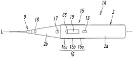
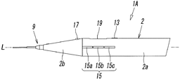
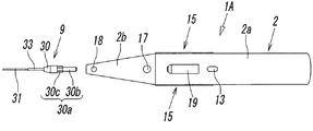
第1実施形態のハンダ付け装置1Aは、図1−図4に示すように、片手に持つように構成されたペン形のボディ2を有している。このボディ2は、金属あるいは合成樹脂等により中空状に形成されたもので、グリップ部を兼ねる本体部2aと、該本体部2aの先端に次第に先細りをなすように形成された円錐部2bとを有し、これら本体部2aと円錐部2bとが、軸線Lに沿ってほぼ真っ直ぐに配置されている。
As shown in FIGS. 1 to 4, the
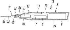
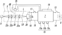
図5の回路図も参照して、前記ボディ2の内部には、半導体レーザーからなるレーザーモジュール5と、該レーザーモジュール5を含むハンダ付け装置1A全体を制御する制御回路7が実装された回路基板6と、前記レーザーモジュール5及び制御回路7に電力を供給するための充電式のバッテリー8とが、該ボディ2の先端側から後端側に向けて前述した順番に配置されて内蔵され、該ボディ2の円錐部2bの先端には、前記レーザーモジュール5から出射されたレーザー光LBをハンダ付け部位10(図10参照)に向けて照射するための照射部材9が取り付けられている。
With reference to the circuit diagram of FIG. 5, a circuit board in which a
また、前記ボディ2の外面には、前記制御回路7とバッテリー8とを結ぶ電源回路14を開閉するための電源スイッチ13と、前記制御回路7による制御モードを切り換えるためのモード切換ボタン15と、前記制御回路7とレーザーモジュール5とを結ぶ照射回路16を開閉し、前記レーザーモジュール5をオン・オフさせてレーザー光LBの照射及び停止を行う照射ボタン17と、前記レーザーモジュール5のオン・オフに連動して点灯及び消灯するインジケーターランプ18と、ハンダ付け装置1Aの動作状態を表示する表示部19とが設けられている。なお、図2においては、電気配線の記載が省略されている。
Further, on the outer surface of the
前記レーザーモジュール5は、半導体からなる発光素子20に電流を流してこの発光素子20をレーザー発振させることにより、この発光素子20からレーザー光LBを出射させるもので、合成樹脂や金属等からなるモジュールケース21の内部に、前記発光素子20と複数の光学レンズ22a,22b,22cとを光軸即ち前記軸線Lに沿って内蔵し、該光学レンズ22a,22b,22cで集光されたレーザー光LBをモジュールケース21の先端に形成された出射口5aから照射部材9に向けて出射するように構成されている。前記レーザー光LBは、例えば、波長800−1000nm、出力3.5−5W程度に設定されている。
The
また、前記レーザーモジュール5には、可視光域にある赤外光からなるガイド光GBを出射させるためのガイド光発生素子25が付設されていて、このガイド光発生素子25から前記レーザー光LBの光軸Lと直交する方向に出射されたガイド光GBを、半透鏡26で前記光軸Lの方向に屈曲させ、該光軸Lに沿って出射することができるように構成されている。前記半透鏡26は、レーザー光LBは透過させるが可視光は全反射する性質を有するものである。前記ガイド光発生素子25は、前記モジュールケース21の内部に設けても、外部に設けても良い。
Further, the
前記ガイド光GBは、前記ハンダ付け部位10にレーザー光LBを照射してハンダ付けする際に、前もってこのガイド光GBをハンダ付け部位10に照射することにより、レーザー光LBの照射位置に照準を合わせるためのもので、該レーザー光LBより低出力(5mW程度)に設定されている。
When the
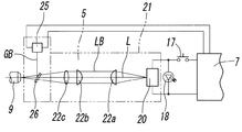
なお、図5においては、前記半透鏡26を第1の光学レンズ22aと第2の光学レンズ22bとの間に配設し、前記ガイド光発生素子25から出射されたガイド光GBをこの半透鏡26で反射させたあと、前記第2の光学レンズ22b及び第3の光学レンズ22cを通じて出射させるようにしているが、図6に示すように、前記半透鏡26を第3の光学レンズ22cの外側(前方側)に配設し、ガイド光発生素子25から出射されたガイド光GBを、該半透鏡26で光軸L方向に反射させて照射部材9に直接入射させるようにすることもできる。
In FIG. 5, the
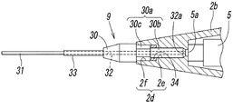
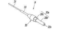
図4、図7、図8から明らかなように、前記照射部材9は、光コネクタ兼用のファイバーホルダー30と、該ファイバーホルダー30に基端部を保持されて先端部が該ファイバーホルダー30から前方に延出する光ファイバー31とを有している。
前記ファイバーホルダー30は、前記ボディ2より小径の円柱状をした部品であって、その中心に前記光ファイバー31が挿入されたファイバー挿入孔32を有すると共に、先端部に前記光ファイバー31を保護するための細管状をした保護管部33を有し、基端部には取付部30aを有していて、この取付部30aを、前記ボディ2の円錐部2bの先端に開口する取付孔2d内に挿入することにより、該ボディ2に着脱自在に取り付けられている。
As is clear from FIGS. 4, 7, and 8, the
The
また、前記取付部30aの基端部には、前記光ファイバー31の基端部が臨む入射口32aが形成され、この入射口32aがボディ2の内部で前記レーザーモジュール5の先端の出射口5aに対向することにより、前記レーザーモジュール5とファイバーホルダー30とが光学的に接続されている。
Further, an
前記照射部材9は、前記ボディ2に着脱自在に取り付けられている。この取り付けのため、前記ファイバーホルダー30の取付部30aには、円柱状をした先端部30bと、六角形等の多角形やその他の非円形状をした回転防止部30cとが形成され、これに対して前記ボディ2の取付孔2dには、前記先端部30bが嵌合する円孔部2eと、前記回転防止部30cが嵌合する非円孔部2fとが形成され、該非円孔部2fの孔底部には永久磁石34が取り付けられていて、この永久磁石34と、鉄などの磁性材で形成さた前記回転防止部30cとを磁気力で相互に吸着させることにより、前記照射部材9が、前記ボディ2対し、決められた一定の向きに、回転を規制された姿勢で安定的に取り付られている。
The
しかし、その他の取付方法を用いることもできる。例えば、図9に示すように、取付部30aの一部に雄螺子部30dを形成すると共に、取付孔2dの一部に雌螺子部2gを形成し、この雌螺子部2g内に前記雄螺子部30dをねじ込む方法を用いることもできる。
However, other mounting methods can also be used. For example, as shown in FIG. 9, a
前記照射部材9はボディ2に対して着脱自在であるため、光ファイバー31の線径が異なる他の照射部材9と交換可能であり、該照射部材9の交換により、ハンダ付け部位10の態様やハンダ付けポイントの大小等に応じて前記レーザー光LBのビーム径を変更することができる。例えば、前記光ファイバー31の線径が0.1mm、0.2mm、0.3mm、0.4mm、0.6mm、0.8mmといった6種類の照射部材9を用意しておけば、レーザー光LBのビーム径を6種類に変更することができる。
Since the
前記モード切換ボタン15は、第1−第3の3つの切換ボタン15a−15cを有している。このうち第1の切換ボタン15aは、前記制御モードを、レーザー光LBの照射が可能な照射モードと、レーザー光LBの照射が不可能な停止モードとに切り換えるためのものであり、また、第2の切換ボタン15bと第3の切換ボタン15cとは、レーザー光LBの出力を増加及び減少させたり、前記ガイド光GBの出射及び停止を行ったり、表示部19の表示を変更したりするためのものである。
The
そして、前記第1の切換ボタン15aで制御モードを照射モードに切り換えると、前記制御回路7により、前記照射回路16が電源回路14に接続されるため、前記照射ボタン17の操作が有効になって前記レーザーモジュール5をオン・オフ操作することができるようになると同時に、前記表示部19に設けられた照射モードランプ36が点灯する。また、前記第1の切換ボタン15aで制御モードを停止モードに切り換えると、前記制御回路7により、前記照射回路16が電源回路14から切り離されるため、前記照射ボタン17の操作が無効になってレーザーモジュール5をオン・オフ操作することができなくなると同時に、前記照射モードランプ36が消灯する。
Then, when the control mode is switched to the irradiation mode with the
一方、前記照射ボタン17は、該照射ボタン17を押している間だけ前記照射回路16を閉じ、離すと該照射回路16を開くように構成されている。従って、前記制御モードを照射モードに切り換えた状態で該照射ボタン17を押すと、該照射ボタン17を押している間だけ前記レーザーモジュール5がオンになってレーザー光LBが出射され、前記照射ボタン17を離して押圧を解除すると、前記レーザーモジュール5がオフになってレーザー光LBの出射が停止し、それに同期して前記インジケーターランプ18が点灯したり消灯したりする。
前記制御モードが停止モードに切り換えられていると、前記照射回路16が電源から切り離されているため、前記照射ボタン17を押してもレーザーモジュール5はオンにならない。
On the other hand, the
When the control mode is switched to the stop mode, the
なお、前記レーザー光LBが照射されているとき、前記インジケーターランプ18が点灯すると同時に、ブザーが鳴ってそのことを作業者に知らせるようにすることもできる。このブザーモードのオン・オフは、前記第2の切換ボタン15bか又は第3の切換ボタン15cによって行うようにする。
When the laser beam LB is being irradiated, the
前記各スイッチ及びボタンとランプとは、操作し易く且つ見易い位置であればボディ2のどの位置に設けても良いが、図示した実施形態では、前記電源スイッチ13と表示部19と照射ボタン17とインジケーターランプ18とが、ボディ2の上面に、該ボディ2の後端側から先端側に向けて前記順番に並べて配設され、前記モード切換ボタン15はボディ2の側面に設けられている。この場合、作業者が右利きであっても左利きであっても簡単に操作できるように、前記モード切換ボタン15は、ボディ2の左右両側面に設けておくことが望ましい。
The switches, buttons, and lamps may be provided at any position on the
前記構成を有するハンダ付け装置1Aを使用し、例えばリフロー式のハンダ付けを行うときの操作は、次の通りである。
即ち、先ず、前記電源スイッチ13をオンにすると共に、前記モード切換ボタン15の第1の切換ボタン15aによって制御モードを照射モードに切り換える。
続いて、前記ボディ2を片手でペンを握るように持ち、図10に示すように、光ファイバー31の先端をハンダ付け部位10に近接させた状態にしたあと、前記照射ボタン17を指で押してレーザーモジュール5を起動させ、レーザー光LBを前記光ファイバー31の先端から前記ハンダ付け部位10に向けて照射する。すると、前記電極部11aに塗布されているハンダ37が該レーザー光LBの熱エネルギーにより溶融され、該電極部11aと前記リード12aとがハンダ付けされる。
The operation when, for example, reflow type soldering is performed by using the
That is, first, the
Subsequently, the
このとき、前記レーザー光LBの誤照射を防止するため、該レーザー光LBをハンダ付け部位10に向けて照射する前に、前記第2の切換ボタン15b又は第3の切換ボタン15cの操作によって前記レーザーモジュール5から前記ガイド光GBを出射させ、このガイド光GBを予めレーザー光LBの照射位置に照射することによって該照射位置に照準を合わせ、その状態で該照射位置に向けて前記レーザー光LBを照射するようにすることが好ましい。
At this time, in order to prevent erroneous irradiation of the laser light LB, the operation of the
一つのハンダ付け部位10のハンダ付けが終了すると、前記照射ボタン17から指を離してその押圧を解除することにより前記レーザー光LBの照射を停止し、その状態でハンダ付け装置1Aを次のハンダ付け部位10に移動させ、同様の操作で該ハンダ付け部位10のハンダ付けを行う。このとき、前記ガイド光GBは、出射させたままである。
When the soldering of one
一方、線状ハンダを用いてハンダ付けを行うこともでき、その場合は、例えば、ハンダ供給装置からハンダ付け部位10に向けて必要量の線状ハンダを自動的に供給しながら、供給された線状ハンダをレーザー光LBで溶融させてハンダ付けすることも、あるいは、前記ハンダ付け装置1Aを持つ手と反対側の手にハンダ供給ノズルを持ち、このハンダ供給ノズルから線状ハンダを供給しながらハンダ付けすることもできる。
On the other hand, soldering can also be performed using linear solder. In that case, for example, the required amount of linear solder is automatically supplied from the solder supply device to the
なお、前記ボディ2は、軸線Lに沿って複数の部分に分離可能なるように構成し、それらを分離することによって前記レーザーモジュール5や回路基板6あるいはバッテリー8等の各部品を点検したり交換したりすることができるように構成することも、あるいは、前記ボディ2の一部又は全部を前記軸線Lを含む面又は該軸線Lと平行な面に沿って開閉自在なるように形成し、該ボディ2を開放することによって前記各部品の点検及び交換を行うことができるように構成することもできる。
The
また、前記第1実施形態の変形例として、前記レーザーモジュール5は動作時に発熱するため、その熱を外部に逃がすため、図11に示すように、ボディ2の少なくとも前記レーザーモジュール5を取り囲む部分に、複数の放熱孔40を設けることができる。この放熱孔40は、円孔であっても、軸線L方向に細長い長孔であっても良く、このような放熱孔40を、ボディ2の周方向及び軸線L方向に規則的又は不規則的に並べて形成することが望ましい。
Further, as a modification of the first embodiment, since the
更に、前記放熱孔40を設けるのと同時に、前記レーザーモジュール5にも、熱を外部に逃がし易くするため、図12に示すように、アルミニウムのような熱伝導性に勝れた金属からなる1つ又は複数の放熱部材41を、モジュールケース21の外面に露出するように設けておくことが望ましい。この放熱部材41は、モジュールケース21の外面から外部に突出しないように形成しても良いが、図13に示すように、フィン状をした複数の放熱部材41を、前記ボディ2の内部においてモジュールケース21から放射状に突出するように形成しても良い。
Further, at the same time as providing the
図14は本発明に係るレーザー溶着装置(ハンダ付け装置)の第2実施形態を示すもので、この第2実施形態のハンダ付け装置1Bが前記第1実施形態のハンダ付け装置1Aと相違する点は、ハンダ付け時にハンダ付け部位10に向けて不活性ガスを噴射するための機構を備えている点である。この不活性ガスは、ハンダ付け時にハンダ及びハンダ付け部位10の酸化を防止するものであって、このような不活性ガスとしては、窒素ガスやアルゴンガス等が使用される。
FIG. 14 shows a second embodiment of the laser welding device (soldering device) according to the present invention, in which the
このため、前記第2実施形態のハンダ付け装置1Bにおいては、ボディ2の内部にガス流路44が形成され、このガス流路44に不活性ガスを導入するためのガス導入口45が前記ボディ2の後端部側面に形成されると共に、前記ガス流路44内の不活性ガスをハンダ付け部位10に向けて噴射するためのガス噴射口46が、前記ボディ2の先端部に、軸線Lに沿って該ボディ2の前方に向けて開口するように形成されている。
そして、前記ガス導入口45に、合成樹脂やゴム等からなる柔軟なガス供給管47が接続され、このガス供給管47を通じてガス源から前記不活性ガスが供給されるように構成されている。
前記ガス噴射口46は1つであっても良いが、好ましくは複数であり、図示した実施形態では、複数のガス噴射口46が、円錐部2bの先端寄りの位置に、該円錐部2bを取り囲むように形成されている。
Therefore, in the
A flexible
The number of the
この場合に好ましくは、前記ガス噴射口46から噴射した不活性ガスが先広がり状に拡散するのを防止するため、前記円錐部2bの先端に、先すぼまりの筒状に形成されたキャップ48を取り付け、このキャップ48の先端のガス流出口48aを光ファイバー31の先端近くに配置させることであり、これにより、不活性ガスをハンダ付け部位10に集中して噴射することが可能になる。
In this case, preferably, in order to prevent the inert gas injected from the
また、前記ガス流路44は、レーザーモジュール5の外周に接した状態で該外周を取り囲む主流路44aと、該主流路44aと前記ガス導入口45とを結ぶ1つ又は複数の孔状をした供給用流路44bとからなっていて、前記供給用流路44bは、前記制御回路7や回路基板6及びバッテリー8等の配置の邪魔にならない場所に設けられている。
Further, the
前記主流路44aは、前記レーザーモジュール5の外周を取り囲んでいるといっても、必ずしも該レーザーモジュール5の円周方向に連続している必要はなく、軸線L方向の隔壁で複数の流路部分に区画されていても良い。
Even though the
このように、前記ガス流路44を前記レーザーモジュール5の外周を取り囲むように形成することにより、このガス流路44を流れる不活性ガスとの接触によって前記レーザーモジュール5が冷却されることになる。従って、前記不活性ガスは、ハンダ付け時にハンダ及びハンダ付け部位10の酸化を防止する機能と、前記レーザーモジュール5を冷却する機能とを兼備するものである。このとき、該不活性ガスは、前記レーザーモジュール5を冷却することにより、熱を吸収して昇温し、昇温した状態で前記ハンダ付け部位10に向けて噴射されることになるため、ハンダ付け部位10の温度低下を来しにくい。
By forming the
前記不活性ガスによって前記レーザーモジュール5が冷却され易くするため、該レーザーモジュール5には、図12及び図13に示すように、アルミニウムのような熱伝導性に勝れた金属からなる1つ又は複数の放熱部材41を、前記主流路44aに面するように設けておくことが望ましい。
In order to facilitate the cooling of the
前記第2実施形態のハンダ付け装置1Bのその他の構成や変形例及び作用は、前記第1実施形態のハンダ付け装置1Aの場合と実質的に同じであるので、両者の主要な同一構成部分に第1実施形態で用いた符号を付してその説明は省略する。
Since the other configurations, modifications, and operations of the
図15は本発明に係るレーザー溶着装置(ハンダ付け装置)の第3実施形態を示すもので、この第3実施形態のハンダ付け装置1Cは、ボディ2がピストル形をしている点で、前記第1実施形態のハンダ付け装置1Aと相違している。
即ち、この第3実施形態のハンダ付け装置1Cのボディ2は、軸線Lに沿って連なる本体部2a及び円錐部2bと、該本体部2aから軸線Lと交叉する方向に延出するグリップ部2cとを有していて、前記本体部2a及び円錐部2bに、レーザーモジュール5と、制御回路7及び回路基板6と、バッテリー8とが収容されると共に、前記電源スイッチ13とインジケーターランプ18と表示部19とモード切換ボタン15とが設けられ、前記グリップ部2cに照射ボタン17とが設けられている。しかし、前記バッテリー8は前記グリップ部2cの内部に収容しても良い。
FIG. 15 shows a third embodiment of the laser welding device (soldering device) according to the present invention. The
That is, the
この第3実施形態のハンダ付け装置1Cのその他の構成や変形例及び作用は、前記第1実施形態のハンダ付け装置1Aの場合と実質的に同じであるので、両者の主要な同一構成部分に第1実施形態で用いた符号を付してその説明は省略する。
Other configurations, modifications, and operations of the
また、前記第3実施形態のハンダ付け装置1Cは、第2実施形態のハンダ付け装置1Bのように、不活性ガスを噴射するための機構を備えることができる。この場合、前記ボディ2の本体部2a及び円錐部2bが、第2実施形態のハンダ付け装置1Bのボディ2と同様に構成される。
Further, the
なお、前記各実施形態において、前記照射ボタン17は、自己保持タイプのものであっても良い。即ち、該照射ボタン17は、それを一度押すか又はオンの位置に切り換えると、そのままオンの状態を維持し、前記レーザーモジュール5がオンになってレーザー光LBが出射され、前記照射ボタン17をもう一度押すか又はオフの位置に切り換えると、該照射ボタン17はオフの状態になり、前記レーザーモジュール5がオフになってレーザー光LBが停止するように構成されていても良い。
In each of the above embodiments, the
また、前記各実施形態において、照射部材9の光ファイバー31は、ファイバーホルダー30から前方に真っ直ぐ延出しているが、図16に示す照射部材9Aのように、保護管部33及び光ファイバー31の先端は折れ曲がっていても良い。あるいは、光ファイバー31がファイバーホルダー30から真っ直ぐ延出する前記照射部材9を、ボディ2の先端に、前記光ファイバー31が軸線Lに沿って延びる位置と、該光ファイバー31が軸線Lに対して傾斜する位置とに、角度調整可能なるように取り付けることもできる。
Further, in each of the above embodiments, the
更に、前記各実施形態においては、充電式のバッテリー8を備えているが、このようなバッテリー8を備えることなく、ボディ2の後端部に受電端子を設け、この受電端子に、交流電源又は直流電源からの給電線を直接接続して使用するように構成することも可能である。
Further, in each of the above embodiments, the
なお、前記実施形態はハンダ付け装置であるが、本発明は、レーザー光で合成樹脂製の部品同士の溶着を行う溶着装置にも適用することができることは、改めて言うまでもないことである。 Although the embodiment is a soldering device, it goes without saying that the present invention can also be applied to a welding device for welding synthetic resin parts with a laser beam.
2 ボディ
5 レーザーモジュール
7 制御回路
9,9A 照射部材
10 ハンダ付け部位
15 モード切換ボタン
17 照射ボタン
20 発光素子
30 ファイバーホルダー
31 光ファイバー
44 ガス流路
45 ガス導入口
46 ガス噴射口
LB レーザー光
GB ガイド光
L 軸線(光軸)
2
Claims (7)
前記照射部材は、前記ボディの先端に取り付けられたファイバーホルダーと、該ファイバーホルダーに基端部を保持されて先端部が該ファイバーホルダーからボデイの前方に向けて延出する光ファイバーとを有する、
ことを特徴とする手動式レーザー溶着装置。 A laser module that emits laser light by oscillating a light emitting element with a laser and a control circuit that controls the laser module are built in a body that has a grip portion for holding a pen with one hand, and the laser. An irradiation member for irradiating the laser beam emitted from the module toward the welding target site and an irradiation button for turning on / off the laser module are provided .
The irradiation member has a fiber holder attached to the tip of the body, and an optical fiber whose base end is held by the fiber holder and whose tip extends from the fiber holder toward the front of the body.
A manual laser welding device characterized by that.
Priority Applications (1)
| Application Number | Priority Date | Filing Date | Title |
|---|---|---|---|
| JP2017030214A JP6832004B2 (en) | 2017-02-21 | 2017-02-21 | Manual laser welding device |
Applications Claiming Priority (1)
| Application Number | Priority Date | Filing Date | Title |
|---|---|---|---|
| JP2017030214A JP6832004B2 (en) | 2017-02-21 | 2017-02-21 | Manual laser welding device |
Publications (2)
| Publication Number | Publication Date |
|---|---|
| JP2018134657A JP2018134657A (en) | 2018-08-30 |
| JP6832004B2 true JP6832004B2 (en) | 2021-02-24 |
Family
ID=63366460
Family Applications (1)
| Application Number | Title | Priority Date | Filing Date |
|---|---|---|---|
| JP2017030214A Active JP6832004B2 (en) | 2017-02-21 | 2017-02-21 | Manual laser welding device |
Country Status (1)
| Country | Link |
|---|---|
| JP (1) | JP6832004B2 (en) |
Families Citing this family (1)
| Publication number | Priority date | Publication date | Assignee | Title |
|---|---|---|---|---|
| JP7468177B2 (en) * | 2020-06-17 | 2024-04-16 | オムロン株式会社 | Laser Processing Equipment |
Family Cites Families (6)
| Publication number | Priority date | Publication date | Assignee | Title |
|---|---|---|---|---|
| JPH0434818Y2 (en) * | 1986-06-12 | 1992-08-19 | ||
| JPH0677638A (en) * | 1992-08-21 | 1994-03-18 | Matsushita Electric Ind Co Ltd | Laser soldering equipment |
| JP2005111531A (en) * | 2003-10-08 | 2005-04-28 | Fuji Electric Holdings Co Ltd | Laser soldering method, and laser soldering equipment |
| JP2005284033A (en) * | 2004-03-30 | 2005-10-13 | Miyachi Technos Corp | Beam shaping device, laser oscillation device, and laser machining device |
| JP2008155246A (en) * | 2006-12-22 | 2008-07-10 | Sumitomo Electric Ind Ltd | Laser beam machine |
| WO2010007852A1 (en) * | 2008-07-16 | 2010-01-21 | 住友電気工業株式会社 | Laser processing apparatus and processing method employed therein |
-
2017
- 2017-02-21 JP JP2017030214A patent/JP6832004B2/en active Active
Also Published As
| Publication number | Publication date |
|---|---|
| JP2018134657A (en) | 2018-08-30 |
Similar Documents
| Publication | Publication Date | Title |
|---|---|---|
| JP2007529870A5 (en) | ||
| RU2004126859A (en) | POWDER MANUAL POWDERED LASER WELDER | |
| JP2008080484A (en) | Hand-held type machine tool | |
| US20090045174A1 (en) | Device for exchanging a nozzle of a vapor plasma burner and nozzle and guard ring | |
| JP2008155246A (en) | Laser beam machine | |
| JP6832004B2 (en) | Manual laser welding device | |
| KR100801049B1 (en) | Ultra-violet ray irradiating apparatus | |
| JP2010524704A (en) | Positioning means and method of using the same | |
| US20030147258A1 (en) | Curing light with plurality of LEDs and corrresponding lenses configured to focus light | |
| JP6832006B2 (en) | Manual laser welding device with irradiation guide | |
| JP2002200100A (en) | Projector | |
| JP4804512B2 (en) | Illuminated nozzle | |
| JP4589520B2 (en) | Endoscope tip manufacturing method and endoscope tip portion | |
| JP2002314151A (en) | Light projecting apparatus | |
| CN210475854U (en) | Light-duty hand-held type laser swing soldered connection | |
| CN210967473U (en) | Hand-held type laser welding head | |
| JP4620751B2 (en) | Photocuring device-base station combination | |
| KR101193214B1 (en) | Focal distance adjust flash flashlight | |
| CN114466678A (en) | System for combining therapeutic laser and curing light | |
| JP4289536B2 (en) | Melt processing apparatus and method using laser beam and arc | |
| CN217370932U (en) | Handheld welding head for optical fiber transmission | |
| JP6441101B2 (en) | Plasma welding equipment | |
| JP7199234B2 (en) | fishing line cutter | |
| JP2004212402A (en) | Light irradiation device | |
| KR100924659B1 (en) | Welding machine |
Legal Events
| Date | Code | Title | Description |
|---|---|---|---|
| A621 | Written request for application examination |
Free format text: JAPANESE INTERMEDIATE CODE: A621 Effective date: 20190917 |
|
| A977 | Report on retrieval |
Free format text: JAPANESE INTERMEDIATE CODE: A971007 Effective date: 20200908 |
|
| A131 | Notification of reasons for refusal |
Free format text: JAPANESE INTERMEDIATE CODE: A131 Effective date: 20200915 |
|
| A521 | Request for written amendment filed |
Free format text: JAPANESE INTERMEDIATE CODE: A523 Effective date: 20201027 |
|
| TRDD | Decision of grant or rejection written | ||
| A01 | Written decision to grant a patent or to grant a registration (utility model) |
Free format text: JAPANESE INTERMEDIATE CODE: A01 Effective date: 20201222 |
|
| A61 | First payment of annual fees (during grant procedure) |
Free format text: JAPANESE INTERMEDIATE CODE: A61 Effective date: 20210118 |
|
| R150 | Certificate of patent or registration of utility model |
Ref document number: 6832004 Country of ref document: JP Free format text: JAPANESE INTERMEDIATE CODE: R150 |
|
| R250 | Receipt of annual fees |
Free format text: JAPANESE INTERMEDIATE CODE: R250 |