EP2329136B1 - Wellenkraftwerk - Google Patents
Wellenkraftwerk Download PDFInfo
- Publication number
- EP2329136B1 EP2329136B1 EP09815731.6A EP09815731A EP2329136B1 EP 2329136 B1 EP2329136 B1 EP 2329136B1 EP 09815731 A EP09815731 A EP 09815731A EP 2329136 B1 EP2329136 B1 EP 2329136B1
- Authority
- EP
- European Patent Office
- Prior art keywords
- power plant
- waves
- plant body
- wave
- wave power
- Prior art date
- Legal status (The legal status is an assumption and is not a legal conclusion. Google has not performed a legal analysis and makes no representation as to the accuracy of the status listed.)
- Not-in-force
Links
- 230000033001 locomotion Effects 0.000 claims description 56
- XLYOFNOQVPJJNP-UHFFFAOYSA-N water Substances O XLYOFNOQVPJJNP-UHFFFAOYSA-N 0.000 claims description 11
- 239000003381 stabilizer Substances 0.000 claims description 7
- 230000001133 acceleration Effects 0.000 claims description 2
- 230000005484 gravity Effects 0.000 claims description 2
- 239000000725 suspension Substances 0.000 claims description 2
- 238000005096 rolling process Methods 0.000 claims 1
- 230000000694 effects Effects 0.000 description 6
- 230000001902 propagating effect Effects 0.000 description 3
- 238000010276 construction Methods 0.000 description 2
- 230000001737 promoting effect Effects 0.000 description 2
- 230000001154 acute effect Effects 0.000 description 1
- 238000004873 anchoring Methods 0.000 description 1
- 230000033228 biological regulation Effects 0.000 description 1
- 230000002301 combined effect Effects 0.000 description 1
- 230000003247 decreasing effect Effects 0.000 description 1
- 230000001419 dependent effect Effects 0.000 description 1
- 230000005611 electricity Effects 0.000 description 1
- 230000001788 irregular Effects 0.000 description 1
- 238000009987 spinning Methods 0.000 description 1
- 230000006641 stabilisation Effects 0.000 description 1
- 238000011105 stabilization Methods 0.000 description 1
- 230000000087 stabilizing effect Effects 0.000 description 1
Images
Classifications
-
- F—MECHANICAL ENGINEERING; LIGHTING; HEATING; WEAPONS; BLASTING
- F03—MACHINES OR ENGINES FOR LIQUIDS; WIND, SPRING, OR WEIGHT MOTORS; PRODUCING MECHANICAL POWER OR A REACTIVE PROPULSIVE THRUST, NOT OTHERWISE PROVIDED FOR
- F03B—MACHINES OR ENGINES FOR LIQUIDS
- F03B13/00—Adaptations of machines or engines for special use; Combinations of machines or engines with driving or driven apparatus; Power stations or aggregates
- F03B13/12—Adaptations of machines or engines for special use; Combinations of machines or engines with driving or driven apparatus; Power stations or aggregates characterised by using wave or tide energy
- F03B13/14—Adaptations of machines or engines for special use; Combinations of machines or engines with driving or driven apparatus; Power stations or aggregates characterised by using wave or tide energy using wave energy
- F03B13/16—Adaptations of machines or engines for special use; Combinations of machines or engines with driving or driven apparatus; Power stations or aggregates characterised by using wave or tide energy using wave energy using the relative movement between a wave-operated member, i.e. a "wom" and another member, i.e. a reaction member or "rem"
- F03B13/20—Adaptations of machines or engines for special use; Combinations of machines or engines with driving or driven apparatus; Power stations or aggregates characterised by using wave or tide energy using wave energy using the relative movement between a wave-operated member, i.e. a "wom" and another member, i.e. a reaction member or "rem" wherein both members, i.e. wom and rem are movable relative to the sea bed or shore
-
- F—MECHANICAL ENGINEERING; LIGHTING; HEATING; WEAPONS; BLASTING
- F03—MACHINES OR ENGINES FOR LIQUIDS; WIND, SPRING, OR WEIGHT MOTORS; PRODUCING MECHANICAL POWER OR A REACTIVE PROPULSIVE THRUST, NOT OTHERWISE PROVIDED FOR
- F03G—SPRING, WEIGHT, INERTIA OR LIKE MOTORS; MECHANICAL-POWER PRODUCING DEVICES OR MECHANISMS, NOT OTHERWISE PROVIDED FOR OR USING ENERGY SOURCES NOT OTHERWISE PROVIDED FOR
- F03G7/00—Mechanical-power-producing mechanisms, not otherwise provided for or using energy sources not otherwise provided for
- F03G7/08—Mechanical-power-producing mechanisms, not otherwise provided for or using energy sources not otherwise provided for recovering energy derived from swinging, rolling, pitching or like movements, e.g. from the vibrations of a machine
-
- F—MECHANICAL ENGINEERING; LIGHTING; HEATING; WEAPONS; BLASTING
- F05—INDEXING SCHEMES RELATING TO ENGINES OR PUMPS IN VARIOUS SUBCLASSES OF CLASSES F01-F04
- F05B—INDEXING SCHEME RELATING TO WIND, SPRING, WEIGHT, INERTIA OR LIKE MOTORS, TO MACHINES OR ENGINES FOR LIQUIDS COVERED BY SUBCLASSES F03B, F03D AND F03G
- F05B2240/00—Components
- F05B2240/90—Mounting on supporting structures or systems
- F05B2240/93—Mounting on supporting structures or systems on a structure floating on a liquid surface
-
- F—MECHANICAL ENGINEERING; LIGHTING; HEATING; WEAPONS; BLASTING
- F05—INDEXING SCHEMES RELATING TO ENGINES OR PUMPS IN VARIOUS SUBCLASSES OF CLASSES F01-F04
- F05B—INDEXING SCHEME RELATING TO WIND, SPRING, WEIGHT, INERTIA OR LIKE MOTORS, TO MACHINES OR ENGINES FOR LIQUIDS COVERED BY SUBCLASSES F03B, F03D AND F03G
- F05B2250/00—Geometry
- F05B2250/40—Movement of component
- F05B2250/44—Movement of component one element moving inside another one, e.g. wave-operated member (wom) moving inside another member (rem)
-
- Y—GENERAL TAGGING OF NEW TECHNOLOGICAL DEVELOPMENTS; GENERAL TAGGING OF CROSS-SECTIONAL TECHNOLOGIES SPANNING OVER SEVERAL SECTIONS OF THE IPC; TECHNICAL SUBJECTS COVERED BY FORMER USPC CROSS-REFERENCE ART COLLECTIONS [XRACs] AND DIGESTS
- Y02—TECHNOLOGIES OR APPLICATIONS FOR MITIGATION OR ADAPTATION AGAINST CLIMATE CHANGE
- Y02E—REDUCTION OF GREENHOUSE GAS [GHG] EMISSIONS, RELATED TO ENERGY GENERATION, TRANSMISSION OR DISTRIBUTION
- Y02E10/00—Energy generation through renewable energy sources
- Y02E10/30—Energy from the sea, e.g. using wave energy or salinity gradient
Definitions
- the invention relates to a wave power plant, comprising at least one floating power plant body and means for converting movement of the floating power plant body into a rotary motion for power takeoff.
- Publication US-4,266,143 discloses a wave power producing apparatus, wherein the objective is to convert the pendulum-like swinging motion of a floating tank into the rotating motion of a rotator. Because of the irregular movement and varying size of waves, it has been difficult or impossible to convert this pendulum-like swinging motion into continuous rotating motion with a high efficiency.
- Publication US-3231749 shows a wave power plant wherein the floating body is tilted or rocked by wave motion. The problem of maintaining a continuous rotating motion exists.
- Publication US-7375436 produces an oscillating motion of the floating body from motion of water waves.
- the oscillating motion of the body causes precession of a spinning gyroscope which is used to drive a motor generator to produce electricity.
- Publication US 524490 shows a wave power plant having a heavy wheel arranged to run upon a circular track on the outer end of a lever. Except for the anchoring means, there is no construction in the water outside the power plant body to cause gyration motion of the power plant body directly from the buoyant force of waves.
- the underlying concept of the invention is to bring a floating power plant body to perform a gyrating movement directly in response to waves, the invention introducing means, by which the waves are caused to generate a gyrating motion or by which the wave-generated gyrating motion is enhanced.
- the floating body of a wave power plant comprises a pontoon or float.
- the rotating parts of a power plant are located inside this shell type body.
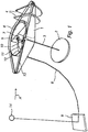
- a floating power plant body 1 is elongated and arcuate, which shape in its part assists in the generation of gyrating motion as an incoming direction A of waves is substantially in line with the body's longitudinal direction or slightly offset from that direction, resulting in an acute angle between the incoming direction A of waves and the body's longitudinal direction.
- the floating power plant body 1 is adapted to perform a gyrating motion directly in response to waves, enabling the gyrating motion to be utilized for setting a rotator 6 in rotating motion.
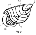
- FIG. 2 is depicted a design for the power plant body 1, which is preferred in view of generating a gyrating motion.
- the power plant body 1 features, near its forward end (in the incoming direction A of waves), level with the waterline, i.e. close to the power plant body's top edge, a cross-section profile R-R, which is inclined on either side of the body in one direction, i.e. to the right as viewed in the propagation direction of waves.
- a cross-sectional curve L-L present in a middle section of the body 1, is inclined in the opposite direction, i.e. to the left. Also in this case, the body has its both sides inclined to the left, as indicated by a dashed-line portion of the curve L-L.
- a cross-sectional curve R-R present at a rearward end of the body, is again inclined to the right on either side of the body.
- the body's curvature and the subsequently described weight and gyro force thereof have each also a gyration promoting effect at a respective stage of a wave.
- each of these effects supports one another and assists in the generation of a gyrating motion as smooth and powerful as possible in diverse wave conditions.
- the power takeoff elements include a rotator 6, which is bearing-mounted for rotation around a gyration shaft 5 and which has its center of gravity at a distance from the gyration shaft 5.
- the rotator 6 is linked to the gyration shaft 5 with a moment arm 7 of desired length.
- gyrating motion of the body 1 can be generated directly from the movement of waves and the wave-generated gyrating motion can be enhanced with subsequently described elements.
- a heavy horizontal flange 2 set in the depth of about a 1 ⁇ 2 wavelength.
- the body 1 is in turn weighted asymmetrically with an inclination to tilt onto the side away from the flange 2.
- the flange 2 and the weighting of the body 1 balance each other out, whereby, in calm water, the power plant floats in such a way that the rotator 6 has its shaft 5, which is at the same time the gyration shaft, in a vertical position.
- the fact that the flange 2 opposes an up-and-down movement creates a lateral swinging force which, together with a swinging force longitudinal of the wave, produces a gyrating motion.
- the length of a suspension chain or cable 3 supporting the flange 2 is adjustable for enabling the adjustment of its depth from a waterline 13 to equal about 1 ⁇ 2 of the length of a wave or some other depth for providing the effect of a desired magnitude.
- Gyrating motion is also assisted by one or more transverse flanges 4, which is or are mounted on the power plant body 1 substantially crosswise to the propagating direction A of waves.
- the transverse flange or flanges 4 is or are located at a distance from the gyration shaft 5, downstream of the gyration shaft in the propagating direction A of waves.
- the flange or flanges 4 prevent the floating power plant body 1 from going along with the wave in an accelerating motion, which falls exactly on such a point at which the body's 1 movement would oppose rotation of the rotator 6 in response to gyrating motion.
- a horizontal movement of the body 1 is principally disallowed and the body 1 moves mainly in a vertical direction in response to the buoyancy of waves, the vertical movement nevertheless occurring asynchronously on various sides of the gyration shaft 5, thus generating a gyrating motion.
- the gyrating motion can also be promoted with a flywheel 11 having a substantially vertical rotating axis.
- the flywheel 11 can be present on the same shaft as the rotator 6 or on a separate shaft.
- the flywheel 11 can derive its rotational energy by way of an increasing gear 10 from the rotator 6.
- the flywheel 11 can also be driven by means of a separate (electric) motor.
- the flywheel 11 has its gyro force deflecting the body's 1 turning action, whereby the wave-generated pitch produces also sideways swinging. The combined effect of these movements generates a gyrating motion.
- the gyro force opposes a wave-generated external force and a longitudinal tilting of the body, which at the same time urges to tilt the gyro, but the gyro translates the external force into a lateral rotation and achieves a lateral swinging of the body.
- the tilting gyro force is at its maximum as the pitching is at its fastest, i.e. on the crest and in the trough of a wave. At this point, the body's listing is also at its maximum.
- the wave power plant includes preferably a computer-controlled RPM stabilizer for the rotator 6.
- the wide-range fluctuation in the RPM of the rotator 6 is a problem.
- a large wave causes a rush, which often ends up in a "counter-hill" as the rotator is in a wrong phase with respect to the next wave.
- the computer-controlled RPM stabilizer monitors the rotating speed of the rotator and allows its fluctuation within a set range, e.g. not more than 10% per revolution. If the rotating speed tends to increase faster than the set value, the automatics shall operate to increase the resistance of a generator. If the RPM tends to decrease faster than what has been determined, the resistance of a generator 12 will be decreased or the rotating speed of the rotator 6 is even increased by feeding energy into the generator.
- the rotation of the plant's rotating parts is smoother and more continuous. Stoppages do not occur and, thus, the energy output is also increased.
- the flywheel 11 may also function as an RPM stabilizer.
- the massive, high-speed rotating flywheel 11, linked to the rotator 6 by way of the gear 10, can be used as a stabilizer for RPM fluctuations the same way as a computer-controlled RPM stabilizer mentioned above. While rotating around a vertical axis, the flywheel 11 provides at the same time a gyro effect as mentioned above.
- the generator 12 can be connected with the flywheel 11.
- the increasing gear 10 can be continuously variable and automatics may take care of the gear ratio regulation so as to achieve a sufficient RPM stabilization for the rotator 6.
- the rotator's 6 phase angle with respect to the gyrating motion is optimized by computer control.
- the computer-controlled phase angle optimizer is a system which monitors the rotator's 6 location in relation to an inclination of the power plant body 1 and endeavors to maintain the phase angle averagely at an optimum. In terms of the output of energy, the most preferred condition would be to have the rotator 6 follow behind the inclination of the gyration shaft 5 with a phase difference of about 90°. This is where the rotator's 6 torque moment is at its maximum.
- the computer-operated phase angle optimizer may also receive advance information about an incoming wave from a wave height or acceleration measuring buoy/sensor 14 positioned in front of the apparatus in the incoming direction of waves.
- All of the described functions relate to the rotator's 6 rotation achieved by means of gyration either by promoting the wave-generated gyrating motion or by independently converting the movement of waves into a gyrating motion , which in turn can be used for rotating the rotator 6. Accordingly, it is possible to employ various combinations of the described functions or all of the functions can be utilized in a single floating power plant.
- the described functions enable providing a stable-in-motion and high-yield power plant.
- the preferred exemplary power plant may feature the elongated arcuate float body 1, which is further provided with the heavy flange 2 suspended alongside the body and with the flywheel 11 as an RPM stabilizer, in addition to which the RPM fluctuations can be stabilized by a load of the generator 12 or by an adjustment of the increasing gear 10 while a phase difference between the rotator's 6 rotation and the body's 1 gyrating motion is optimized by means of computer control.
- the power plant body may consist of several interconnected floats.
- the gyro force enables implementing a totally symmetrical gyrating power plant body, although the efficiency can be increased by an appropriate asymmetry of the shape or construction, by means of which the vertical buoyancy of propagating waves is adapted to work at alternate times on alternate sides of the body.
- the underwater horizontal flange enables implementing a symmetrical gyrating body. In a high-performance power plant it is possible to provide a single very large body with a plurality of gyrating units as described, which could be mounted on a common body e.g. by means of springs.
Landscapes
- Engineering & Computer Science (AREA)
- Chemical & Material Sciences (AREA)
- Combustion & Propulsion (AREA)
- Mechanical Engineering (AREA)
- General Engineering & Computer Science (AREA)
- Other Liquid Machine Or Engine Such As Wave Power Use (AREA)
Claims (9)
- Wellenkraftwerk, umfassend:mindestens einen schwimmenden Kraftwerkkörper (1) mit einem vorderen Ende, das ausgelegt ist, um der Ausbreitungsrichtung der Wellen zugewandt zu sein, einem hinteren Ende und einem mittleren Abschnitt dazwischen,ein flanschförmiges Gewicht (2), das exzentrisch von dem schwimmenden Kraftwerkkörper (1) hängt und das unter einer Wasserlinie (13) des schwimmenden Kraftwerkkörpers in einem Abstand von der Wasserlinie liegt, um einer Auf- und Abbewegung des Körpers entgegenzutreten,ein System zum Bewegungsumwandeln des schwimmenden Kraftwerkkörpers in eine Drehbewegung zum Energieabnehmen, das einen Rotator (6) umfasst, der zur Drehung um eine aufrechte Rotationswelle (5) herum gelagert ist und der einen Schwerpunkt in einem Abstand von der Rotationswelle (5) hat, undein computergesteuertes System, das konfiguriert ist, um eine Ausgangsenergie durch den Rotator, der einer Neigung der Rotationswelle folgt, zu optimieren, wobei der schwimmende Kraftwerkkörper (1) angepasst ist, um eine Rotationsbewegung in Wellen in Zusammenwirkung mit einer Schwingbewegung, die durch die Auftriebskraft von Wellen erzeugt wird, durchzuführen, wobei die Rotationbewegung eine Kombination aus Schwingbewegungen in Seiten- und Längsrichtungen des Kraftwerkkörpers ist, die durch die Schwingbewegung verursacht werden, die durch die Auftriebskraft von Wellen erzeugt wird, undwobei der schwimmende Kraftwerkkörper ferner Folgendes umfasst:
einen oder mehrere Querflansche (4), der oder die außerhalb des schwimmenden Kraftwerkkörpers in einer kreuzweisen Position relativ zu einer Ausbreitungsrichtung (A) von Wellen montiert ist oder sind, wobei sich der Querflansch oder die Querflansche (4) in einem Abstand von der Rotationswelle (5) stromabwärts von der Rotationswelle in der Ausbreitungsrichtung (A) von Wellen befindet oder befinden. - Wellenkraftwerk nach Anspruch 1, dadurch gekennzeichnet, dass, wenn in der Ausbreitungsrichtung von Wellen betrachtet, die Flanken des Kraftwerkkörpers (1), die mit der Wasserlinie des Kraftwerkkörpers auf einer Ebene sind, schräglaufend in eine erste Richtung an dem vorderen Ende und dann in eine zweite Richtung entgegengesetzt der ersten Richtung an dem mittleren Abschnitt und wiederum in die erste Richtung an dem hinteren Ende gekrümmt sind, wodurch die Auftriebskraft von Wellen zum Rollen und Stampfen des Kraftwerkkörpers zum Erzeugen einer Rotationsbewegung direkt als Reaktion auf Wellen führt.
- Wellenkraftwerk nach Anspruch 1 oder 2, dadurch gekennzeichnet, dass der schwimmende Kraftwerkkörper ferner ein Schwungrad (11) umfasst, dessen Drehachse im Wesentlichen auf einer Rotationswelle (5) des schwimmenden Kraftwerkkörpers oder auf einer getrennten vertikalen Welle liegt und dessen Rotationskraft die Drehbewegung des schwimmenden Kraftwerkkörpers von der Bewegungsrichtung, die durch die Auftriebskraft von Wellen erzeugt wird, umlenkt.
- Wellenkraftwerk nach Anspruch 1, dadurch gekennzeichnet, dass das Wellenkraftwerk einen computergesteuerten Drehzahl-Stabilisator für den Rotator (6) aufweist.
- Wellenkraftwerk nach Anspruch 1 oder 2, dadurch gekennzeichnet, dass der Wellenkraftwerkkörper ein Ponton oder Schwimmer (1) ist, der länglich und bogenförmig ist.
- Wellenkraftwerk nach Anspruch 1, dadurch gekennzeichnet, dass ein/e Aufhängungskette oder - kabel (3) für das flanschförmige Gewicht (2) bezüglich ihrer/seiner Länge anpassbar ist.
- Wellenkraftwerk nach Anspruch 1, dadurch gekennzeichnet, dass der schwimmende Kraftwerkkörper (1) derart asymmetrisch gewichtet ist, dass die Gewichtung eine Neigung, die durch das flanschförmige Gewicht (2) entsteht, ausgleicht, wodurch sich in ruhigem Wasser die Rotatorwelle (5) und jeweils die Rotationswelle in einer im Wesentlichen vertikalen Position befinden.
- Wellenkraftwerk nach einem der Ansprüche 1-3, dadurch gekennzeichnet, dass der schwimmende Kraftwerkkörper ein schalenartiges Gehäuse für das Wellenkraftwerk bildet, in dessen Inneren sich die Drehteile des Wellenkraftwerks befinden, durch die die Rotationsbewegung des schwimmenden Kraftwerkkörpers in elektrische Energie umgewandelt wird.
- Wellenkraftwerk nach Anspruch 1, dadurch gekennzeichnet, dass der computerbetriebene Phasenwinkeloptimierer angepasst ist, um Vorrückinformationen über eine eingehende Welle von einer/m Wellenhöhen- oder Beschleunigungsmessboje/- sensor (14) zu empfangen, die/der vor dem Wellenkraftwerk in der Eingangsrichtung von Wellen positioniert ist.
Applications Claiming Priority (2)
| Application Number | Priority Date | Filing Date | Title |
|---|---|---|---|
| FI20085911A FI122615B (fi) | 2008-09-26 | 2008-09-26 | Aaltovoimala |
| PCT/FI2009/050758 WO2010034888A1 (en) | 2008-09-26 | 2009-09-23 | Wave power plant |
Publications (3)
| Publication Number | Publication Date |
|---|---|
| EP2329136A1 EP2329136A1 (de) | 2011-06-08 |
| EP2329136A4 EP2329136A4 (de) | 2013-04-17 |
| EP2329136B1 true EP2329136B1 (de) | 2018-05-02 |
Family
ID=39852299
Family Applications (1)
| Application Number | Title | Priority Date | Filing Date |
|---|---|---|---|
| EP09815731.6A Not-in-force EP2329136B1 (de) | 2008-09-26 | 2009-09-23 | Wellenkraftwerk |
Country Status (12)
| Country | Link |
|---|---|
| US (1) | US8915077B2 (de) |
| EP (1) | EP2329136B1 (de) |
| JP (1) | JP5547735B2 (de) |
| CN (1) | CN102165181B (de) |
| AR (1) | AR073650A1 (de) |
| AU (1) | AU2009295772B2 (de) |
| CA (1) | CA2738203C (de) |
| CL (1) | CL2009001901A1 (de) |
| ES (1) | ES2675778T3 (de) |
| FI (1) | FI122615B (de) |
| NO (1) | NO2329136T3 (de) |
| WO (1) | WO2010034888A1 (de) |
Families Citing this family (19)
| Publication number | Priority date | Publication date | Assignee | Title |
|---|---|---|---|---|
| US8519557B2 (en) * | 2005-11-07 | 2013-08-27 | Gwave Llc | System for producing energy through the action of waves |
| US9976535B2 (en) | 2005-11-07 | 2018-05-22 | Gwave Llc | System for producing energy through the action of waves |
| FI123295B (fi) | 2011-11-17 | 2013-02-15 | Wello Oy | Aaltovoimala |
| FI20116152A7 (fi) * | 2011-11-17 | 2013-05-18 | Wello Oy | Aaltovoimala |
| ES2579704T3 (es) | 2012-04-17 | 2016-08-16 | Wello Oy | Procedimiento para convertir la energía de las olas en electricidad por medio de una central undimotriz y central undimotriz |
| GB2501737A (en) * | 2012-05-02 | 2013-11-06 | Nicholas James Adkins | Tilting plate electrical generator |
| KR102155385B1 (ko) | 2012-06-04 | 2020-09-11 | 그웨이브 엘엘씨 | 파도의 작용을 통한 에너지 생산 시스템 |
| CN102705139B (zh) * | 2012-06-26 | 2014-04-16 | 西北工业大学 | 一种回转体水下航行器发电装置 |
| FI124925B (fi) * | 2013-09-18 | 2015-03-31 | Wello Oy | Gyratoiva aaltovoimala |
| FR3017424B1 (fr) * | 2014-02-12 | 2016-01-29 | Felix Elefant | Convertisseur de puissance houlomotrice exploitant le mouvement orbital d'un chariot pesant |
| FI125500B (fi) * | 2014-08-19 | 2015-10-30 | Wello Oy | Aaltovoimalan roottori |
| US10533531B2 (en) * | 2015-06-28 | 2020-01-14 | Vassilios Vamvas | Eccentrically rotating mass turbine |
| US10947951B2 (en) * | 2015-06-28 | 2021-03-16 | Vassilios Vamvas | Eccentrically rotating mass turbine |
| US10060408B2 (en) | 2015-06-28 | 2018-08-28 | Vassilios Vamvas | Eccentrically rotating mass turbine |
| DK3721072T3 (da) * | 2017-12-06 | 2022-01-10 | Torino Politecnico | System til generering af elektrisk energi ud fra havets bølgebevægelse |
| RO134451B1 (ro) * | 2020-03-23 | 2022-07-29 | Pitt-Codruţ Tudorache | Sistem de captare a energiei valurilor şi transformarea acesteia în energie electrică |
| US12253068B2 (en) * | 2020-05-27 | 2025-03-18 | Yaroslav TSAPOVSKI | Energy capture from oscillating object |
| CN113998088B (zh) * | 2021-09-24 | 2023-02-17 | 东南大学 | 波浪能和太阳能复合供电的自供能无人潜航器 |
| IT202100026360A1 (it) | 2021-12-10 | 2023-06-10 | Torino Politecnico | Dispositivo giroscopico pendolare per la conversione di energia e sistema per la generazione di energia elettrica comprendente tale dispositivo |
Family Cites Families (16)
| Publication number | Priority date | Publication date | Assignee | Title |
|---|---|---|---|---|
| US524490A (en) * | 1894-08-14 | Wave-motor | ||
| US1682176A (en) * | 1928-08-28 | Wave motor | ||
| US1584293A (en) * | 1925-02-12 | 1926-05-11 | Hegenbarth Francis | Wave motor |
| US3231749A (en) | 1963-04-12 | 1966-01-25 | Thiokol Chemical Corp | Wave power generator |
| US4266143A (en) * | 1979-09-19 | 1981-05-05 | Ng Ting F | Apparatus for producing electrical energy from ocean waves |
| JPS60230567A (ja) * | 1984-05-01 | 1985-11-16 | Tomotoshi Tokuno | 波力発電装置 |
| JPS62118066A (ja) | 1985-11-16 | 1987-05-29 | Osamu Hachiro | 波浪発電:波面上の傾斜・空気力・加速力を同一方向回転運動にする発電方法 |
| JPS6429674A (en) * | 1987-07-23 | 1989-01-31 | Shinwa Car Kk | Wave power generating device |
| US6561856B1 (en) * | 2001-02-07 | 2003-05-13 | Vladislav Vasilyevich Gorshkov | Power floating production and ship propulsion supported by gyroscope and energized by seas |
| JP4469620B2 (ja) * | 2004-01-23 | 2010-05-26 | 博 神吉 | ジャイロ式波力発電装置 |
| US7375436B1 (en) * | 2004-11-12 | 2008-05-20 | Aaron Goldin | Gyroscope-based electricity generator |
| US7755224B2 (en) | 2005-11-07 | 2010-07-13 | Glenn Beane | System for producing electricity through the action of waves on floating platforms |
| US7239038B1 (en) * | 2005-12-16 | 2007-07-03 | Harris Corporation | Apparatus for electrical signal generation based upon movement and associated methods |
| US7737569B2 (en) * | 2006-10-24 | 2010-06-15 | Seadyne Energy Systems, Llc | System and method for converting ocean wave energy into electricity |
| US7453165B2 (en) | 2006-10-24 | 2008-11-18 | Seadyne Energy Systems, Llc | Method and apparatus for converting ocean wave energy into electricity |
| FI125703B (fi) | 2007-03-30 | 2016-01-15 | Wello Oy | Aaltovoimala |
-
2008
- 2008-09-26 FI FI20085911A patent/FI122615B/fi not_active IP Right Cessation
-
2009
- 2009-09-22 AR ARP090103628A patent/AR073650A1/es active IP Right Grant
- 2009-09-23 WO PCT/FI2009/050758 patent/WO2010034888A1/en not_active Ceased
- 2009-09-23 CN CN200980138256.6A patent/CN102165181B/zh not_active Expired - Fee Related
- 2009-09-23 AU AU2009295772A patent/AU2009295772B2/en not_active Ceased
- 2009-09-23 CA CA2738203A patent/CA2738203C/en not_active Expired - Fee Related
- 2009-09-23 JP JP2011528379A patent/JP5547735B2/ja not_active Expired - Fee Related
- 2009-09-23 ES ES09815731.6T patent/ES2675778T3/es active Active
- 2009-09-23 EP EP09815731.6A patent/EP2329136B1/de not_active Not-in-force
- 2009-09-23 US US13/119,424 patent/US8915077B2/en not_active Expired - Fee Related
- 2009-09-23 NO NO09815731A patent/NO2329136T3/no unknown
- 2009-09-25 CL CL2009001901A patent/CL2009001901A1/es unknown
Non-Patent Citations (1)
| Title |
|---|
| None * |
Also Published As
| Publication number | Publication date |
|---|---|
| FI20085911L (fi) | 2010-03-27 |
| WO2010034888A1 (en) | 2010-04-01 |
| ES2675778T3 (es) | 2018-07-12 |
| EP2329136A4 (de) | 2013-04-17 |
| US20110265468A1 (en) | 2011-11-03 |
| AU2009295772B2 (en) | 2014-10-23 |
| CA2738203A1 (en) | 2010-04-01 |
| US8915077B2 (en) | 2014-12-23 |
| CL2009001901A1 (es) | 2010-09-10 |
| FI122615B (fi) | 2012-04-30 |
| AU2009295772A1 (en) | 2010-04-01 |
| CN102165181A (zh) | 2011-08-24 |
| CN102165181B (zh) | 2015-06-24 |
| CA2738203C (en) | 2017-05-16 |
| JP2012503739A (ja) | 2012-02-09 |
| JP5547735B2 (ja) | 2014-07-16 |
| EP2329136A1 (de) | 2011-06-08 |
| NO2329136T3 (de) | 2018-09-29 |
| AR073650A1 (es) | 2010-11-24 |
| FI20085911A0 (fi) | 2008-09-26 |
Similar Documents
| Publication | Publication Date | Title |
|---|---|---|
| EP2329136B1 (de) | Wellenkraftwerk | |
| JP5497781B2 (ja) | 波の動きによってエネルギーを生成するシステム | |
| US8519557B2 (en) | System for producing energy through the action of waves | |
| JP4713476B2 (ja) | 沖合で使用される風力タービン | |
| US8915078B2 (en) | System for producing energy through the action of waves | |
| US9976535B2 (en) | System for producing energy through the action of waves | |
| CN101688511A (zh) | 海浪发电装置 | |
| JP2017509829A (ja) | オフセットされたフロートを有する波エネルギー発電施設 | |
| FI125302B (fi) | Menetelmä vesiaaltojen energian muuttamiseksi sähköksi aaltovoimalalla ja aaltovoimala | |
| EP2872773B1 (de) | Wellenkraftwerk | |
| KR102234907B1 (ko) | 기능성을 향상시킨 스크류형 유체 발전장치 | |
| EP3047139B1 (de) | Rotierendes wellenkraftwerk | |
| WO2017198899A1 (en) | Device for transporting vessel by wave power | |
| AU2015264803A1 (en) | System for producing energy through the action of waves | |
| WO2010040894A1 (en) | Wave power plant |
Legal Events
| Date | Code | Title | Description |
|---|---|---|---|
| PUAI | Public reference made under article 153(3) epc to a published international application that has entered the european phase |
Free format text: ORIGINAL CODE: 0009012 |
|
| 17P | Request for examination filed |
Effective date: 20110426 |
|
| AK | Designated contracting states |
Kind code of ref document: A1 Designated state(s): AT BE BG CH CY CZ DE DK EE ES FI FR GB GR HR HU IE IS IT LI LT LU LV MC MK MT NL NO PL PT RO SE SI SK SM TR |
|
| AX | Request for extension of the european patent |
Extension state: AL BA RS |
|
| DAX | Request for extension of the european patent (deleted) | ||
| A4 | Supplementary search report drawn up and despatched |
Effective date: 20130320 |
|
| RIC1 | Information provided on ipc code assigned before grant |
Ipc: F03B 13/14 20060101AFI20130314BHEP Ipc: F03B 13/20 20060101ALI20130314BHEP Ipc: F03G 7/08 20060101ALI20130314BHEP |
|
| 17Q | First examination report despatched |
Effective date: 20170324 |
|
| GRAP | Despatch of communication of intention to grant a patent |
Free format text: ORIGINAL CODE: EPIDOSNIGR1 |
|
| GRAJ | Information related to disapproval of communication of intention to grant by the applicant or resumption of examination proceedings by the epo deleted |
Free format text: ORIGINAL CODE: EPIDOSDIGR1 |
|
| INTG | Intention to grant announced |
Effective date: 20171012 |
|
| INTG | Intention to grant announced |
Effective date: 20171017 |
|
| GRAP | Despatch of communication of intention to grant a patent |
Free format text: ORIGINAL CODE: EPIDOSNIGR1 |
|
| INTG | Intention to grant announced |
Effective date: 20171027 |
|
| INTG | Intention to grant announced |
Effective date: 20171027 |
|
| INTC | Intention to grant announced (deleted) | ||
| INTG | Intention to grant announced |
Effective date: 20171120 |
|
| GRAS | Grant fee paid |
Free format text: ORIGINAL CODE: EPIDOSNIGR3 |
|
| GRAA | (expected) grant |
Free format text: ORIGINAL CODE: 0009210 |
|
| RIN1 | Information on inventor provided before grant (corrected) |
Inventor name: PAAKKINEN, HEIKKI |
|
| RAP1 | Party data changed (applicant data changed or rights of an application transferred) |
Owner name: WELLO OY |
|
| AK | Designated contracting states |
Kind code of ref document: B1 Designated state(s): AT BE BG CH CY CZ DE DK EE ES FI FR GB GR HR HU IE IS IT LI LT LU LV MC MK MT NL NO PL PT RO SE SI SK SM TR |
|
| REG | Reference to a national code |
Ref country code: GB Ref legal event code: FG4D |
|
| REG | Reference to a national code |
Ref country code: CH Ref legal event code: EP Ref country code: AT Ref legal event code: REF Ref document number: 995537 Country of ref document: AT Kind code of ref document: T Effective date: 20180515 |
|
| REG | Reference to a national code |
Ref country code: DE Ref legal event code: R096 Ref document number: 602009052143 Country of ref document: DE |
|
| REG | Reference to a national code |
Ref country code: IE Ref legal event code: FG4D |
|
| REG | Reference to a national code |
Ref country code: ES Ref legal event code: FG2A Ref document number: 2675778 Country of ref document: ES Kind code of ref document: T3 Effective date: 20180712 |
|
| REG | Reference to a national code |
Ref country code: NO Ref legal event code: T2 Effective date: 20180502 |
|
| REG | Reference to a national code |
Ref country code: NL Ref legal event code: MP Effective date: 20180502 |
|
| REG | Reference to a national code |
Ref country code: LT Ref legal event code: MG4D |
|
| PG25 | Lapsed in a contracting state [announced via postgrant information from national office to epo] |
Ref country code: LT Free format text: LAPSE BECAUSE OF FAILURE TO SUBMIT A TRANSLATION OF THE DESCRIPTION OR TO PAY THE FEE WITHIN THE PRESCRIBED TIME-LIMIT Effective date: 20180502 Ref country code: FI Free format text: LAPSE BECAUSE OF FAILURE TO SUBMIT A TRANSLATION OF THE DESCRIPTION OR TO PAY THE FEE WITHIN THE PRESCRIBED TIME-LIMIT Effective date: 20180502 Ref country code: SE Free format text: LAPSE BECAUSE OF FAILURE TO SUBMIT A TRANSLATION OF THE DESCRIPTION OR TO PAY THE FEE WITHIN THE PRESCRIBED TIME-LIMIT Effective date: 20180502 Ref country code: BG Free format text: LAPSE BECAUSE OF FAILURE TO SUBMIT A TRANSLATION OF THE DESCRIPTION OR TO PAY THE FEE WITHIN THE PRESCRIBED TIME-LIMIT Effective date: 20180802 |
|
| PG25 | Lapsed in a contracting state [announced via postgrant information from national office to epo] |
Ref country code: NL Free format text: LAPSE BECAUSE OF FAILURE TO SUBMIT A TRANSLATION OF THE DESCRIPTION OR TO PAY THE FEE WITHIN THE PRESCRIBED TIME-LIMIT Effective date: 20180502 Ref country code: LV Free format text: LAPSE BECAUSE OF FAILURE TO SUBMIT A TRANSLATION OF THE DESCRIPTION OR TO PAY THE FEE WITHIN THE PRESCRIBED TIME-LIMIT Effective date: 20180502 Ref country code: GR Free format text: LAPSE BECAUSE OF FAILURE TO SUBMIT A TRANSLATION OF THE DESCRIPTION OR TO PAY THE FEE WITHIN THE PRESCRIBED TIME-LIMIT Effective date: 20180803 Ref country code: HR Free format text: LAPSE BECAUSE OF FAILURE TO SUBMIT A TRANSLATION OF THE DESCRIPTION OR TO PAY THE FEE WITHIN THE PRESCRIBED TIME-LIMIT Effective date: 20180502 |
|
| REG | Reference to a national code |
Ref country code: AT Ref legal event code: MK05 Ref document number: 995537 Country of ref document: AT Kind code of ref document: T Effective date: 20180502 |
|
| PG25 | Lapsed in a contracting state [announced via postgrant information from national office to epo] |
Ref country code: PT Free format text: LAPSE BECAUSE OF FAILURE TO SUBMIT A TRANSLATION OF THE DESCRIPTION OR TO PAY THE FEE WITHIN THE PRESCRIBED TIME-LIMIT Effective date: 20180903 |
|
| PG25 | Lapsed in a contracting state [announced via postgrant information from national office to epo] |
Ref country code: DK Free format text: LAPSE BECAUSE OF FAILURE TO SUBMIT A TRANSLATION OF THE DESCRIPTION OR TO PAY THE FEE WITHIN THE PRESCRIBED TIME-LIMIT Effective date: 20180502 Ref country code: PL Free format text: LAPSE BECAUSE OF FAILURE TO SUBMIT A TRANSLATION OF THE DESCRIPTION OR TO PAY THE FEE WITHIN THE PRESCRIBED TIME-LIMIT Effective date: 20180502 Ref country code: EE Free format text: LAPSE BECAUSE OF FAILURE TO SUBMIT A TRANSLATION OF THE DESCRIPTION OR TO PAY THE FEE WITHIN THE PRESCRIBED TIME-LIMIT Effective date: 20180502 Ref country code: AT Free format text: LAPSE BECAUSE OF FAILURE TO SUBMIT A TRANSLATION OF THE DESCRIPTION OR TO PAY THE FEE WITHIN THE PRESCRIBED TIME-LIMIT Effective date: 20180502 Ref country code: RO Free format text: LAPSE BECAUSE OF FAILURE TO SUBMIT A TRANSLATION OF THE DESCRIPTION OR TO PAY THE FEE WITHIN THE PRESCRIBED TIME-LIMIT Effective date: 20180502 Ref country code: SK Free format text: LAPSE BECAUSE OF FAILURE TO SUBMIT A TRANSLATION OF THE DESCRIPTION OR TO PAY THE FEE WITHIN THE PRESCRIBED TIME-LIMIT Effective date: 20180502 Ref country code: CZ Free format text: LAPSE BECAUSE OF FAILURE TO SUBMIT A TRANSLATION OF THE DESCRIPTION OR TO PAY THE FEE WITHIN THE PRESCRIBED TIME-LIMIT Effective date: 20180502 |
|
| REG | Reference to a national code |
Ref country code: DE Ref legal event code: R097 Ref document number: 602009052143 Country of ref document: DE |
|
| PG25 | Lapsed in a contracting state [announced via postgrant information from national office to epo] |
Ref country code: SM Free format text: LAPSE BECAUSE OF FAILURE TO SUBMIT A TRANSLATION OF THE DESCRIPTION OR TO PAY THE FEE WITHIN THE PRESCRIBED TIME-LIMIT Effective date: 20180502 |
|
| PLBE | No opposition filed within time limit |
Free format text: ORIGINAL CODE: 0009261 |
|
| STAA | Information on the status of an ep patent application or granted ep patent |
Free format text: STATUS: NO OPPOSITION FILED WITHIN TIME LIMIT |
|
| REG | Reference to a national code |
Ref country code: DE Ref legal event code: R119 Ref document number: 602009052143 Country of ref document: DE |
|
| 26N | No opposition filed |
Effective date: 20190205 |
|
| PG25 | Lapsed in a contracting state [announced via postgrant information from national office to epo] |
Ref country code: MC Free format text: LAPSE BECAUSE OF FAILURE TO SUBMIT A TRANSLATION OF THE DESCRIPTION OR TO PAY THE FEE WITHIN THE PRESCRIBED TIME-LIMIT Effective date: 20180502 |
|
| REG | Reference to a national code |
Ref country code: CH Ref legal event code: PL |
|
| GBPC | Gb: european patent ceased through non-payment of renewal fee |
Effective date: 20180923 |
|
| PG25 | Lapsed in a contracting state [announced via postgrant information from national office to epo] |
Ref country code: SI Free format text: LAPSE BECAUSE OF FAILURE TO SUBMIT A TRANSLATION OF THE DESCRIPTION OR TO PAY THE FEE WITHIN THE PRESCRIBED TIME-LIMIT Effective date: 20180502 |
|
| REG | Reference to a national code |
Ref country code: BE Ref legal event code: MM Effective date: 20180930 |
|
| PG25 | Lapsed in a contracting state [announced via postgrant information from national office to epo] |
Ref country code: LU Free format text: LAPSE BECAUSE OF NON-PAYMENT OF DUE FEES Effective date: 20180923 |
|
| PG25 | Lapsed in a contracting state [announced via postgrant information from national office to epo] |
Ref country code: DE Free format text: LAPSE BECAUSE OF NON-PAYMENT OF DUE FEES Effective date: 20190402 |
|
| PG25 | Lapsed in a contracting state [announced via postgrant information from national office to epo] |
Ref country code: LI Free format text: LAPSE BECAUSE OF NON-PAYMENT OF DUE FEES Effective date: 20180930 Ref country code: CH Free format text: LAPSE BECAUSE OF NON-PAYMENT OF DUE FEES Effective date: 20180930 Ref country code: BE Free format text: LAPSE BECAUSE OF NON-PAYMENT OF DUE FEES Effective date: 20180930 Ref country code: FR Free format text: LAPSE BECAUSE OF NON-PAYMENT OF DUE FEES Effective date: 20180930 |
|
| PG25 | Lapsed in a contracting state [announced via postgrant information from national office to epo] |
Ref country code: GB Free format text: LAPSE BECAUSE OF NON-PAYMENT OF DUE FEES Effective date: 20180923 |
|
| PGFP | Annual fee paid to national office [announced via postgrant information from national office to epo] |
Ref country code: NO Payment date: 20190926 Year of fee payment: 11 |
|
| PG25 | Lapsed in a contracting state [announced via postgrant information from national office to epo] |
Ref country code: MT Free format text: LAPSE BECAUSE OF NON-PAYMENT OF DUE FEES Effective date: 20180923 |
|
| PG25 | Lapsed in a contracting state [announced via postgrant information from national office to epo] |
Ref country code: TR Free format text: LAPSE BECAUSE OF FAILURE TO SUBMIT A TRANSLATION OF THE DESCRIPTION OR TO PAY THE FEE WITHIN THE PRESCRIBED TIME-LIMIT Effective date: 20180502 |
|
| PG25 | Lapsed in a contracting state [announced via postgrant information from national office to epo] |
Ref country code: HU Free format text: LAPSE BECAUSE OF FAILURE TO SUBMIT A TRANSLATION OF THE DESCRIPTION OR TO PAY THE FEE WITHIN THE PRESCRIBED TIME-LIMIT; INVALID AB INITIO Effective date: 20090923 |
|
| PG25 | Lapsed in a contracting state [announced via postgrant information from national office to epo] |
Ref country code: MK Free format text: LAPSE BECAUSE OF NON-PAYMENT OF DUE FEES Effective date: 20180502 Ref country code: CY Free format text: LAPSE BECAUSE OF FAILURE TO SUBMIT A TRANSLATION OF THE DESCRIPTION OR TO PAY THE FEE WITHIN THE PRESCRIBED TIME-LIMIT Effective date: 20180502 |
|
| PG25 | Lapsed in a contracting state [announced via postgrant information from national office to epo] |
Ref country code: IS Free format text: LAPSE BECAUSE OF FAILURE TO SUBMIT A TRANSLATION OF THE DESCRIPTION OR TO PAY THE FEE WITHIN THE PRESCRIBED TIME-LIMIT Effective date: 20180902 |
|
| REG | Reference to a national code |
Ref country code: NO Ref legal event code: MMEP |
|
| PG25 | Lapsed in a contracting state [announced via postgrant information from national office to epo] |
Ref country code: NO Free format text: LAPSE BECAUSE OF NON-PAYMENT OF DUE FEES Effective date: 20200930 |
|
| PGFP | Annual fee paid to national office [announced via postgrant information from national office to epo] |
Ref country code: IT Payment date: 20210803 Year of fee payment: 13 Ref country code: IE Payment date: 20210803 Year of fee payment: 13 |
|
| PGFP | Annual fee paid to national office [announced via postgrant information from national office to epo] |
Ref country code: ES Payment date: 20211005 Year of fee payment: 13 |
|
| PG25 | Lapsed in a contracting state [announced via postgrant information from national office to epo] |
Ref country code: IE Free format text: LAPSE BECAUSE OF NON-PAYMENT OF DUE FEES Effective date: 20220923 |
|
| PG25 | Lapsed in a contracting state [announced via postgrant information from national office to epo] |
Ref country code: IT Free format text: LAPSE BECAUSE OF NON-PAYMENT OF DUE FEES Effective date: 20220923 |
|
| REG | Reference to a national code |
Ref country code: ES Ref legal event code: FD2A Effective date: 20231102 |
|
| PG25 | Lapsed in a contracting state [announced via postgrant information from national office to epo] |
Ref country code: ES Free format text: LAPSE BECAUSE OF NON-PAYMENT OF DUE FEES Effective date: 20220924 |
|
| PG25 | Lapsed in a contracting state [announced via postgrant information from national office to epo] |
Ref country code: ES Free format text: LAPSE BECAUSE OF NON-PAYMENT OF DUE FEES Effective date: 20220924 |