EP2328488B1 - Cervical occluder - Google Patents
Cervical occluder Download PDFInfo
- Publication number
- EP2328488B1 EP2328488B1 EP09789160.0A EP09789160A EP2328488B1 EP 2328488 B1 EP2328488 B1 EP 2328488B1 EP 09789160 A EP09789160 A EP 09789160A EP 2328488 B1 EP2328488 B1 EP 2328488B1
- Authority
- EP
- European Patent Office
- Prior art keywords
- fluid
- support member
- resistant material
- expandable support
- cervical
- Prior art date
- Legal status (The legal status is an assumption and is not a legal conclusion. Google has not performed a legal analysis and makes no representation as to the accuracy of the status listed.)
- Not-in-force
Links
Images


Classifications
-
- A—HUMAN NECESSITIES
- A61—MEDICAL OR VETERINARY SCIENCE; HYGIENE
- A61B—DIAGNOSIS; SURGERY; IDENTIFICATION
- A61B17/00—Surgical instruments, devices or methods, e.g. tourniquets
- A61B17/0057—Implements for plugging an opening in the wall of a hollow or tubular organ, e.g. for sealing a vessel puncture or closing a cardiac septal defect
-
- A—HUMAN NECESSITIES
- A61—MEDICAL OR VETERINARY SCIENCE; HYGIENE
- A61B—DIAGNOSIS; SURGERY; IDENTIFICATION
- A61B17/00—Surgical instruments, devices or methods, e.g. tourniquets
- A61B17/12—Surgical instruments, devices or methods, e.g. tourniquets for ligaturing or otherwise compressing tubular parts of the body, e.g. blood vessels, umbilical cord
- A61B17/12022—Occluding by internal devices, e.g. balloons or releasable wires
- A61B17/12027—Type of occlusion
- A61B17/12031—Type of occlusion complete occlusion
-
- A—HUMAN NECESSITIES
- A61—MEDICAL OR VETERINARY SCIENCE; HYGIENE
- A61B—DIAGNOSIS; SURGERY; IDENTIFICATION
- A61B17/00—Surgical instruments, devices or methods, e.g. tourniquets
- A61B17/12—Surgical instruments, devices or methods, e.g. tourniquets for ligaturing or otherwise compressing tubular parts of the body, e.g. blood vessels, umbilical cord
- A61B17/12022—Occluding by internal devices, e.g. balloons or releasable wires
- A61B17/12027—Type of occlusion
- A61B17/12036—Type of occlusion partial occlusion
-
- A—HUMAN NECESSITIES
- A61—MEDICAL OR VETERINARY SCIENCE; HYGIENE
- A61B—DIAGNOSIS; SURGERY; IDENTIFICATION
- A61B17/00—Surgical instruments, devices or methods, e.g. tourniquets
- A61B17/12—Surgical instruments, devices or methods, e.g. tourniquets for ligaturing or otherwise compressing tubular parts of the body, e.g. blood vessels, umbilical cord
- A61B17/12022—Occluding by internal devices, e.g. balloons or releasable wires
- A61B17/12027—Type of occlusion
- A61B17/1204—Type of occlusion temporary occlusion
-
- A—HUMAN NECESSITIES
- A61—MEDICAL OR VETERINARY SCIENCE; HYGIENE
- A61B—DIAGNOSIS; SURGERY; IDENTIFICATION
- A61B17/00—Surgical instruments, devices or methods, e.g. tourniquets
- A61B17/12—Surgical instruments, devices or methods, e.g. tourniquets for ligaturing or otherwise compressing tubular parts of the body, e.g. blood vessels, umbilical cord
- A61B17/12022—Occluding by internal devices, e.g. balloons or releasable wires
- A61B17/12099—Occluding by internal devices, e.g. balloons or releasable wires characterised by the location of the occluder
-
- A—HUMAN NECESSITIES
- A61—MEDICAL OR VETERINARY SCIENCE; HYGIENE
- A61B—DIAGNOSIS; SURGERY; IDENTIFICATION
- A61B17/00—Surgical instruments, devices or methods, e.g. tourniquets
- A61B17/12—Surgical instruments, devices or methods, e.g. tourniquets for ligaturing or otherwise compressing tubular parts of the body, e.g. blood vessels, umbilical cord
- A61B17/12022—Occluding by internal devices, e.g. balloons or releasable wires
- A61B17/12131—Occluding by internal devices, e.g. balloons or releasable wires characterised by the type of occluding device
- A61B17/12136—Balloons
-
- A—HUMAN NECESSITIES
- A61—MEDICAL OR VETERINARY SCIENCE; HYGIENE
- A61B—DIAGNOSIS; SURGERY; IDENTIFICATION
- A61B17/00—Surgical instruments, devices or methods, e.g. tourniquets
- A61B17/12—Surgical instruments, devices or methods, e.g. tourniquets for ligaturing or otherwise compressing tubular parts of the body, e.g. blood vessels, umbilical cord
- A61B17/12022—Occluding by internal devices, e.g. balloons or releasable wires
- A61B17/12131—Occluding by internal devices, e.g. balloons or releasable wires characterised by the type of occluding device
- A61B17/12168—Occluding by internal devices, e.g. balloons or releasable wires characterised by the type of occluding device having a mesh structure
- A61B17/12172—Occluding by internal devices, e.g. balloons or releasable wires characterised by the type of occluding device having a mesh structure having a pre-set deployed three-dimensional shape
-
- A—HUMAN NECESSITIES
- A61—MEDICAL OR VETERINARY SCIENCE; HYGIENE
- A61B—DIAGNOSIS; SURGERY; IDENTIFICATION
- A61B17/00—Surgical instruments, devices or methods, e.g. tourniquets
- A61B17/42—Gynaecological or obstetrical instruments or methods
-
- A—HUMAN NECESSITIES
- A61—MEDICAL OR VETERINARY SCIENCE; HYGIENE
- A61B—DIAGNOSIS; SURGERY; IDENTIFICATION
- A61B17/00—Surgical instruments, devices or methods, e.g. tourniquets
- A61B2017/00831—Material properties
- A61B2017/00889—Material properties antimicrobial, disinfectant
-
- A—HUMAN NECESSITIES
- A61—MEDICAL OR VETERINARY SCIENCE; HYGIENE
- A61B—DIAGNOSIS; SURGERY; IDENTIFICATION
- A61B17/00—Surgical instruments, devices or methods, e.g. tourniquets
- A61B2017/00831—Material properties
- A61B2017/00893—Material properties pharmaceutically effective
-
- A—HUMAN NECESSITIES
- A61—MEDICAL OR VETERINARY SCIENCE; HYGIENE
- A61B—DIAGNOSIS; SURGERY; IDENTIFICATION
- A61B17/00—Surgical instruments, devices or methods, e.g. tourniquets
- A61B2017/00831—Material properties
- A61B2017/00938—Material properties hydrophobic
-
- A—HUMAN NECESSITIES
- A61—MEDICAL OR VETERINARY SCIENCE; HYGIENE
- A61B—DIAGNOSIS; SURGERY; IDENTIFICATION
- A61B17/00—Surgical instruments, devices or methods, e.g. tourniquets
- A61B2017/00831—Material properties
- A61B2017/00951—Material properties adhesive
-
- A—HUMAN NECESSITIES
- A61—MEDICAL OR VETERINARY SCIENCE; HYGIENE
- A61B—DIAGNOSIS; SURGERY; IDENTIFICATION
- A61B17/00—Surgical instruments, devices or methods, e.g. tourniquets
- A61B17/42—Gynaecological or obstetrical instruments or methods
- A61B2017/4216—Operations on uterus, e.g. endometrium
- A61B2017/4225—Cervix uteri
-
- A—HUMAN NECESSITIES
- A61—MEDICAL OR VETERINARY SCIENCE; HYGIENE
- A61M—DEVICES FOR INTRODUCING MEDIA INTO, OR ONTO, THE BODY; DEVICES FOR TRANSDUCING BODY MEDIA OR FOR TAKING MEDIA FROM THE BODY; DEVICES FOR PRODUCING OR ENDING SLEEP OR STUPOR
- A61M2210/00—Anatomical parts of the body
- A61M2210/14—Female reproductive, genital organs
- A61M2210/1433—Uterus
-
- A—HUMAN NECESSITIES
- A61—MEDICAL OR VETERINARY SCIENCE; HYGIENE
- A61M—DEVICES FOR INTRODUCING MEDIA INTO, OR ONTO, THE BODY; DEVICES FOR TRANSDUCING BODY MEDIA OR FOR TAKING MEDIA FROM THE BODY; DEVICES FOR PRODUCING OR ENDING SLEEP OR STUPOR
- A61M5/00—Devices for bringing media into the body in a subcutaneous, intra-vascular or intramuscular way; Accessories therefor, e.g. filling or cleaning devices, arm-rests
- A61M5/14—Infusion devices, e.g. infusing by gravity; Blood infusion; Accessories therefor
- A61M5/142—Pressure infusion, e.g. using pumps
- A61M5/14244—Pressure infusion, e.g. using pumps adapted to be carried by the patient, e.g. portable on the body
- A61M5/14276—Pressure infusion, e.g. using pumps adapted to be carried by the patient, e.g. portable on the body specially adapted for implantation
Definitions
- This patent document pertains generally to apparatus to treat physiological conditions of pregnancy. More particularly, but not by way of limitation, this patent document pertains to apparatus and kits which, when installed or used, occlude or partially occlude a cervix or other location of membrane rupture to contain amniotic fluid within the uterine cavity.
- PROM preterm-PROM
- US United States
- PROM is most commonly caused by a bacterial infection, by smoking, or by a defect in the structure of the amniotic membrane, uterus, or cervix. This condition is termed spontaneous PROM. In rare cases, the rupture can heal, but in most cases of preterm PROM, labor begins within one week after rupture. Accordingly, one of the most common complications of preterm PROM is premature delivery and its associated risks, including perinatal and neonatal complications. Neonates surviving preterm PROM may develop sequelae, such as malpresentation, cord compression, oligohydramnios, necrotizing enterocolitis, neurologic impairment, intraventricular hemorrhage, or respiratory distress syndrome, and 1- 2% even face the risk of fetal death. These sequelae are most common when PROM occurs before 32 weeks gestation and results in premature delivery.
- PROM can also be the result of iatrogenic causes due to surgical manipulations during pregnancy. Fetoscopic procedures, amniocentesis, and amnioreduction are associated with a risk for PROM.
- WO 2008/046050 A relates to methods and apparatus for occluding a lumen of a body cavity, more preferably the lower uterine segment and/or cervix of a woman, according to the preamble of claim 1.
- US 6,375,970 B1 relates to materials and methods for reducing the incidence of preterm birth involving the use of polymeric compositions.
- US 2003/219492 A1 relates to compositions and methods for use in treatment of premature rupture of membranes.
- US 6,350,463 B1 relates to a method of treatment for premature rupture of membranes in pregnancy.
- the present inventors have recognized, among other things, that it would be useful to provide a means to not only prolong pregnancy and advance fetal development, particularly when PROM occurs before 32 weeks, but to also prevent continuing leakage of amniotic fluid while pregnancy is prolonged, such as to reduce or minimize adverse fetal outcomes.
- the present apparatus is configured to occlude or partially occlude a cervical canal, the internal opening of the cervical canal (cervical os), or a uterine side wall rupture location, such as to inhibit or prevent bacterial access and leakage of amniotic fluid resulting from PROM.
- the present apparatus can include an expandable scaffold, frame, cage or stent, or other support member of a biocompatible and non-toxic material.
- the support member can include a top portion having a first diameter and a bottom portion having a second diameter less, which is less than the first diameter.
- the support member can include an expandable stent of a suitable length and substantially uniform diameter to be inserted into a non-dilated cervical canal.
- the support member can be self-expanding or actively expandable, such as by a catheter-delivered balloon.
- the apparatus further includes a fluid-resistant fabric, polymer, mesh, substance or other material placed over or otherwise coupled to at least the top portion of the support member (i.e., an innermost portion of the support member, which, when implanted, is inserted nearest to the internal cervical os).
- Fluid-resistant materials can include water-resistant, water-impermeable, fluid-impermeable or similarly impervious or repellant materials.
- the fluid-resistant material can be made of any biocompatible and non-toxic material, such as GORE-TEX® or other tightly woven fluid-resistant, nano-fiber material, polytetrafluoroethylene (PTFE), or expanded PTFE.
- the fluid-resistant material includes a coating, such as a silicone-coated material.
- an exemplary method of using the present apparatus or kits can include temporarily occluding or partially occluding a cervical canal, an internal cervical os, or a uterine side wall rupture location to extend pregnancy after PROM.
- the method can comprise inserting into the cervical canal for spontaneous PROM or through an abdominal wall for iatrogenic PROM, an expandable support member that has been covered, coated or otherwise coupled on at least a top side portion with a fluid-resistant material.
- the methodology may also be employed in an effort to prevent fluid loss after fetoscopic manipulations within the uterus to minimize the frequency of post-operative PROM.
- Preterm or premature birth is a complication in approximately 12% of US pregnancies, and about 30-40% of these cases are due to PROM.
- the causes vary, including inflection, and a number of anatomical or medical conditions are implicated. Twenty-three weeks is considered by many to be the earliest possible gestational age for viability-if PROM occurs before 23 weeks, it will often lead to loss of a fetus through natural or surgical means. Every day of extension of pregnancy can decrease the severity of fetal impairment due to prematurity between 23 and 28 weeks gestation; thus, maximizing the duration of pregnancy is clinically important.
- apparatus and kits configured to occlude or partially occlude a cervical canal, an internal cervical os, or a uterine side wall rupture location, such as to inhibit or prevent leakage of amniotic fluid resulting from PROM, are disclosed.
- the apparatus provides a replacement membrane and potentially a barrier to ascending infection, insertable by a treating physician, which may allow an otherwise abnormal pregnancy to progress normally. It is believed, and initial studies have shown, the apparatus can reduce fetal mortality and morbidity, allow for simple and safe insertion and removal, restore anatomical function, minimize infection, and allow for full-term or near full-term birth, such as from an early PROM event to between about 28 to about 34 weeks gestation.
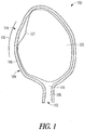
- FIG. 1 illustrates some anatomical tissue structures 100 associated with pregnancy, including an amniotic membrane 102 for enclosing a fetus, a uterus 104, a uterine side wall 106, and a cervix (including a cervical canal 108 and an internal cervical os 110 ).
- the amniotic membrane 102 is not vascularized, slow to heal, uniquely configured, and is not easily accessible. Moreover, the location of an amniotic membrane rupture can be difficult to determine.
- the present apparatus and kits which are configured to inhibit or prevent leakage of amniotic fluid from the uterus 104 due to PROM, can provide great benefits not currently achievable in a safe and effective manner.
- a transvaginal access route 112 is used to implant a present apparatus including a support member and a fluid-resistant material.
- the transvaginal route 112 can traverse the vagina and the cervical canal 108 before entering the internal cervical os 110. Because a PROM patient has leakage of amniotic fluid due to an amniotic membrane 102 rupture, position of the patient so that the cervical canal 108 is raised above the uterus 104, i.e., the Trendelenburg position, can help create space in the uterus 104 near the internal cervical os 110 for insertion of the apparatus.
- a transabdominal access route 114 is used to implant a present apparatus including a support member and a fluid-resistant material.
- the transabdominal access route 114 extends though a portion of an abdominal wall 116 and provides a means to inhibit or prevent leakage of amniotic fluid from an amniotic membrane rupture 116, near a uterine side wall 106, directly in cases of surgical manipulations within the uterus 104.
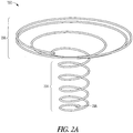
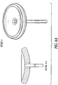
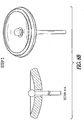
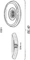
- FIGS. 2A-2B illustrate isometric views of example support members 202.
- the support member 202 can include a stent-like or other expandable structure that is transvaginally insertable 112 ( FIG. 1 ) and can be deployed through, and fixated with, walls of the cervix.
- the support member 202 includes a stent-like structure, such as Boston Scientific's WALLSTENTTM ILIAC ENDOPROSTHESIS product.
- the support member 202 can include a locating cylinder portion 204 and an integrated or attached diaphragm portion 206.
- the locating cylinder portion 204 can be configured to remain in the cervical canal 108 ( FIG. 1 ) and serve anchoring purposes by expanding against wall portions of the cervical canal 108.
- the diaphragm portion 206 can be configured to support a fluid-resistant material, as shown in FIGS. 3A-3C , which contact wall portions of an amniotic membrane 102 ( FIG. 1 ) or a uterus 104 ( FIG. 1 ) to reduce or prevent loss of amniotic fluid.
- the support member 202 does not include a locating cylinder portion 204.
- the support member 202 does not include a diaphragm portion 206, but rather assumes a uniform diameter, expandable stent structure.
- the support member 202 can include various dimensions, materials, and structure configurations.
- the locating cylinder portion 204 can have a deployed, expanded diameter between about 0.25 centimeters (cm) to about 2.0 cm, and more preferably between about 1.0 cm to about 1.5 cm, and a pre-deployment (i.e., unexpanded) diameter between about 3 millimeters (mm) to about 8 mm.
- the locating cylinder portion 204 can have a length of about 0.75 cm to about 2.5 cm.
- the diaphragm portion 206 can have a deployed, expanded diameter of about 3 cm to about 4 cm, and a pre-deployment diameter between about 3 mm to about 8 mm.
- the support member 202 can include a coil-like structure. In some examples, as shown in FIG. 2B , the support member 202 can include a mushroom-like structure. To aid in removal, the support member 202 can include a retrieval loop 208 at or near a bottom end portion (i.e., an outermost portion of the support member, which, when implanted, is nearest the exterior of a patient).
- the support member 202 or portions thereof can be configured to flex to fit local tissue variation at the time of implantation.
- the support member 202 or portions thereof can be configured to conform to progressive changes in tissue over time, such as can be common during the gestational cycle.
- the support member 202 includes Nitinol (a nickel titanium alloy) or other shape memory or expandable, conformable material.
- the support member 202 can include 0.254 mm (0.010 inch) diameter elastic Nitinol wire, which when exposed to body temperatures, assumes a pre-formed shape upon implantation.
- the support member 202 resists cellular in-growth and adhesions, while in other examples, the support member 202 allows for or promotes selected cellular in-growth or adhesions.
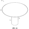
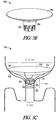
- FIGS. 3A-3C illustrate an isometric view of various biocompatible apparatus 300 including a support member 302 and a fluid-resistant material 304.
- the apparatus 300 includes an expandable, biocompatible support member 302 and a fluid-resistant material 304 in the form of a fluid-resistant fabric or polymer.
- one or both of the support member 302 or the fluid-resistant material 304 is coated or impregnated with bacterial control compounds to provide antibacterial release during use.
- one or both of the support member 302 or the fluid-resistant material 304 is coated or impregnated with an antimicrobial agent, such as nano silver or chlorhexidine.
- the antimicrobial agents can provide broad antibiotic and yeast coverage to a patient.
- the fluid-resistant material 304 can have a deployed, expanded diameter of about 3 cm to about 4 cm, and a pre-deployment diameter between about 3 mm to about 8 mm.
- FIGS. 3A and 3B illustrate that a top portion 308 of the support member 302 (i.e., an innermost portion of the support member, which, when implanted, is inserted nearest to an internal cervical os 110 ( FIG. 1 )) can open and position the fluid-resistant material 304 over the uterine side of the internal cervical os (see, e.g., FIG. 4 ).
- the fluid-resistant material 304 can then extend at least partially down a length of the support member 302 for sealing purposes.
- the fluid-resistant material 304 extends completely down the length of the support member 302; while in the example of FIG. 3B , the fluid-resistant material 304 extends only about 30-50% down the length of the support member 302. In some examples, it has proven helpful to not cover a bottom portion of the support member 302 to aid in apparatus removal via an exposed retrieval loop.
- the fluid-resistant material 304 shown in FIGS. 3A and 3B includes PTFE or ePTFE, both of which are biocompatible and conformal materials.
- PTFE or ePTFE tube of material can be heated and blow-molded using gas pressure.
- This blow-molded polymer tube can be coupled with the top portion 308 of the support member 302 using one or more crimps, one or more stitches, an adhesive, heat or other similar types of bonding, for example.
- FIG. 3C illustrates that a top portion 308 of the support member 302 can be coupled to more than one fluid-resistant member 304.
- the expandable support member 302 can be covered or coated on the top side portion 308 with a fluid-resistant material 305, such as GORE-TEX's® DUALMESH® PLUS Biomaterial product or other piece of fabric that is pliable, easy to work with, repels water, and optionally can be impregnated with anti-infection agents.
- Materials like GORE-TEX's® DUALMESH® PLUS include a plurality of small holes that can allow for tissue incorporation. Thus, over time, portions of the material can become integral with surrounding bodily tissue via tissue in-growth.
- the fluid-resistant material 305 has a thickness about 0.25 cm to about 0.75 cm and is stitched to the support member 302 using a biocompatible thread.
- a second fluid-resistant material 306 can be coupled to the top portion 308 of the support member 302 in a manner similar to a parachute coupling to a pack.
- a first side 330 of the second fluid-resistant material 306 can be configured to promote cell adhesion.
- a second side 332 of the second fluid resistant material 306 can be coated with a water-activated adhesive to help bond the material 306 to underlying uterine tissues to promote sealing. It is believed that an apparatus 300 including more than one fluid-resistant member 304, as shown in FIG. 3C , can provide enhanced functionality (e.g., via redundant sealing) and may ease deployment during implantation via an atraumatic, extremely flexible top end portion.
- an apparatus 400 can be transvaginally inserted 112 and can be deployed through a cervical canal 108 and an internal cervical os 110 such that a fluid-resistant material 404 is centered over the area of the cervix and maintained in position with a support member 402 that projects through the cervical canal 108.
- An outer edge portion of the fluid-resistant material 404 can rest on an upper-facing surface of the uterus 104, as shown schematically in FIG. 4 . It has been found that cervical changes often occur as the gestation period advances.
- these changes can include: a decrease in the cervical canal 108 length, a dilation of the cervical canal 108, a softening of the cervix, or a changing of the cervix from a posterior to an anterior position.
- one or both of the support member 402 and the fluid-resistant material 404 can be configured to conform to the cervical changes to help ensure proper sealing and diminish leaking of amniotic fluid from the uterus 104.
- the resistance of the fluid-resistant material 404 can be directional, such that it can be resistant to fluid penetration from a first direction 410 (e.g., from a uterus toward a vagina), but can permit fluid penetration from a second direction 412 (e.g., from within the support member 402 or administered from outside the body, through the vagina and support member 402, to the underside of the fluid-resistant material 404 ).
- the fluid-resistant material 404 is fluid-impermeable in the first direction 410 at intrauterine pressures of about 20 millimeter of mercury (mmHg) to about 33 mmHg. This fluid-impermeability can allow amniotic fluid to refill the uterus 104 and fetal space without leaking through the cervical canal 108.
- the fluid-resistance directionality of the fluid-resistant material 404 can be particularly useful to permit the apparatus 400 to be configured to allow diffusion or other delivery of a pharmaceutical drug composition (e.g., an antibiotic) or other substance through the covering material 404 while the support member 402 is implanted within the cervical canal 412 of a patient.
- a pharmaceutical drug composition e.g., an antibiotic
- the fluid-resistant material 404 can be infused or coated with a pharmaceutical drug or other substance composition.
- FIG. 5 illustrates an example apparatus 500 including a reservoir 520.
- the reservoir 520 is configured to store a pharmaceutical drug composition or other substance to be delivered to a patient.
- the reservoir can be carried at least partially within a support member 502, and can include means to allow drug or other substance delivery on a sustained release basis (e.g., days, weeks, or months) to the patient.
- a top portion 522 of the apparatus i.e., an innermost portion of the apparatus, which, when implanted, is inserted nearest to an amniotic membrane 102 ( FIG. 1 )
- the pore 524 can be constructed with a specific geometry appropriate to control the rate of release of the pharmaceutical drug composition or other substance to the uterus 104 ( FIG. 1 ) or tissues within or near the uterus.
- a micro-pump could be employed within the apparatus 500 to forcibly expel the drug composition or other substance from the reservoir 520 at a desired rate.
- the reservoir 520 can include a distally-located port or other opening 526 allowing the reservoir 520 to be filled or re-filled after the apparatus 500 is deployed within a cervical canal 108 ( FIG. 1 ) and internal cervical os 110 ( FIG. 1 ). In this way, the apparatus 500 can optionally remain small enough to easily pass through a transvaginal access route 112 ( FIG. 1 ), for example, to a desired membrane rupture location.
- the pharmaceutical composition can be in the form of a solid, a concentrated aqueous or other solution, a resin suspension, or combination thereof.
- the reservoir 520 can be molded or otherwise formed from a flexible material that is impermeable to the drug or other substance which will fill the reservoir 520.
- the reservoir 520 can be formed by a channel through an interior of the support member 502.
- a wick extension from the reservoir 520 can be provided to aid in medication release to the uterus 104 or tissues within or near the uterus.
- the wick extension can be secured within the reservoir 520 in fluid communication with the drug or other substance stored therein, and can extend through the pore 524, for example.
- the wick extension can be formed of a material suitable to transmit medication from the reservoir 520 to the patient, such as an absorbent, cloth-like material. The use of a wick extension can help assure constant contact between the drug or other substance stored within the reservoir 520 and desired tissues of the patient.
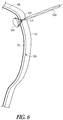
- FIG. 6 illustrates a schematic view of an example apparatus 600 including a support member 602 and a fluid-resistant material 604 retained within a uterine side wall 106 adjacent an abdomen wall 116.
- This second type of PROM is known as iatrogenic PROM and occurs most commonly as a complication of fetoscopy.
- iatrogenic PROM an amniotic membrane 102 rupture occurs somewhere on the side of the uterus 104 with amniotic fluid tracking between the membrane 102 and the uterine side wall 106 for a distance until it gets to the internal cervical os 110.
- an apparatus 600 which is smaller than the apparatus disclosed above and configured for cervical placement.
- This smaller apparatus 600 can be implanted via a transabdominal access route 114 for the prevention of iatrogenic PROM.
- a location cylinder portion of the support member 602 can have a deployed, expanded diameter between about 0.25 cm to about 0.5 cm and a length of about 0.25 cm to about 0.5 cm.
- the fluid-resistant material 604 can have a deployed, expanded diameter of about 0.75 cm to about 1.25 cm, such as about 1.0 cm.
- a detachable string 630 can be used to pull the fluid-resistant material 604 back up against the rupture in the amniotic membrane 102 during implantation.
- the transabdominal apparatus 600 can be implanted using a catheter. While it is not always possible to determine the location of an iatrogenic rupture accurately, when the location can be determined, direct sealing of the rupture using the apparatus 600 can be beneficial.
- a larger apparatus configured for cervical placement can be used in conjunction with apparatus 600 to further prevent amniotic fluid from leaking out of the uterus 104 and through a cervical canal 108 ( FIG. 1 ).
- a retail kit may also be packaged for consumer purchase.
- the kit may include an apparatus comprising a support member and a fluid-resistant material covering or otherwise coupled to a portion of the support member.
- the kit may also include a set of instructions for using the apparatus.
- the kit includes a pharmaceutical drug composition or other substance incorporated with the fluid-resistant material or stored in a reservoir carried by the support member, thereby allowing a treating physician to customize an amount and delivery means of drug or other substance applied to a patient.
- the kit includes one or more insertion or removal tools for implanting and withdrawing the apparatus.
- FIG. 7 illustrates an example method of using an apparatus including a support member and a fluid-resistant material to temporarily occlude or partially occlude a cervical canal, a cervical os, or a uterine side wall rupture location after PROM.
- an apparatus including an expandable support member and a fluid-resistant material, is optionally positioned in an applicator device, such as a delivery catheter, having an adjustable mechanical stop to ensure proper implant depth.
- the apparatus can be configured to be implanted with a single hand of a treating physician through a vagina to the cervical canal. Implantation can be facilitated by the applicator device.
- the applicator device can have an inner diameter between about 0.25 cm to about 1 cm and a length of about 35 cm. In other examples, the length of the applicator device can be less than 35 cm.
- the expandable support member e.g., Nitinol wire coil
- the coil shape see, e.g., FIG. 2A
- the fluid-resistant material coupled to a top portion of the support member can also be at least partially pulled into the cannula.
- the apparatus is implanted adjacent at least one of an amniotic membrane, a cervix, or a uterine side wall.
- the applicator device is advanced through the cervix or abdomen (either visually or under guidance).
- the expandable support member starts to emerge from the cannula, it is no longer constrained and beings to recover its coiled or otherwise expanded shape.
- the support member “remembers” its shape, it can pull and expand the fluid-resistant material into position and form a cupped, domed or disc-shaped cap.
- the bottom portions of the support member can expand in the cervical canal or an abdominal access route, at 706.
- the fluid-resistant material can extend partially into the cervix or an amniotic membrane to help ensure a seal with bodily tissue. Proper placement/implantation of the apparatus can be verified by physician visualization or sonography.
- the method can further include performing cerclage stitching about the cervix, to temporarily seal or occlude the cervical canal and assure the apparatus is not expelled from the cervical canal until delivery of the fetus is to occur or until desired.
- the method of 710 is only used to treat spontaneous PROM and not iatrogenic PROM.
- the apparatus can be removed.
- removal of the apparatus is performed using a special remover device.
- removal of the apparatus is performed using existing hospital tools or equipment.
- the remover device can be configured to hook a retrieval loop at an outermost, bottom end of an implanted apparatus, force can then be applied, and the apparatus can be removed.
- FIGS. 8A-8E illustrate an example of an apparatus and method of use such as for cervical occlusion.
- an occlusion device delivery cannula can be inserted through the cervix just proximal of the cervical os on the uterine side.
- the occlusion device can be inflated, such as with isotonic saline (or similar medical fluid), such as for providing a cushion against the fetal head, and forming a deployment void in the uterine cavity.
- the occlusion device can be fully inflated, and released from the delivery cannula.
- the proximal end of the device can include exposed Nitinol (NiTi) struts in a serpentine (or "daisy) configuration, which can expand due to body temperature, and can purchase the cervical canal wall.
- the exposed struts can also enable reformation of the mucus plug, such as for providing a secondary barrier to ascending infection.
- the isotonic fluid drains from the occlusion device, forming a membrane barrier at the uterine side cervical os, such as for forming a plug positioned and partially sealed by the NiTi wire "daisy" and allowing the membrane to form a flap-type seal.
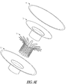
- FIG. 8E shows an example of an exploded view of the device, with these components:
- construction can include RF welding or other bonding of items 2 & 3, encapsulating item 1 therebetween, and then RF welding or bonding item 4 on top.
- the present apparatus can include an expandable support member of a biocompatible and non-toxic material.
- the support member can include a top portion having a first diameter and a bottom portion having a second diameter, which is less than the first diameter.
- the support member can include an expandable stent of a suitable length and substantially uniform diameter to be inserted in a non-dilated cervical canal or a transabdominal access route.
- the apparatus further includes a fluid-resistant fabric, polymer, substance or other material placed over or otherwise coupled to at least the top portion of the support member.
- the present apparatus and kits are believed to provide a safe and effective means to inhibit or prevent continuing loss of amniotic fluid from the uterus (thereby restoring membrane function) after PROM has occurred. In this way, pregnancy can be prolonged to advance fetal development and adverse events to the fetus resulting from decreased amniotic fluid can be diminished. Additionally, the present apparatus and kits can provide a patient the benefit of a continuous pharmacologic effect via drug or other substance release from a reservoir.
- the terms “a” or “an” are used, as is common in patent documents, to include one or more than one, independent of any other instances or usages of "at least one” or “one or more.”
- the term “or” is used to refer to a nonexclusive or, such that “A or B” includes “A but not B,” “B but not A,” and “A and B,” unless otherwise indicated.
- the terms “about” and “approximately” are used to refer to an amount that is nearly, almost, or in the vicinity of being equal to a stated amount.
- the membranes of pregnancy or similar is used to refer to the particular anatomy of the human membrane system that is formed to enclose a fetus.
Landscapes
- Health & Medical Sciences (AREA)
- Surgery (AREA)
- Life Sciences & Earth Sciences (AREA)
- Molecular Biology (AREA)
- General Health & Medical Sciences (AREA)
- Veterinary Medicine (AREA)
- Engineering & Computer Science (AREA)
- Biomedical Technology (AREA)
- Heart & Thoracic Surgery (AREA)
- Medical Informatics (AREA)
- Public Health (AREA)
- Animal Behavior & Ethology (AREA)
- Nuclear Medicine, Radiotherapy & Molecular Imaging (AREA)
- Reproductive Health (AREA)
- Vascular Medicine (AREA)
- Cardiology (AREA)
- Gynecology & Obstetrics (AREA)
- Pregnancy & Childbirth (AREA)
- Surgical Instruments (AREA)
- Prostheses (AREA)
Description
- Benefit of priority is hereby claimed to
U.S. Provisional Patent Application Serial No. 61/089,609 - This patent document pertains generally to apparatus to treat physiological conditions of pregnancy. More particularly, but not by way of limitation, this patent document pertains to apparatus and kits which, when installed or used, occlude or partially occlude a cervix or other location of membrane rupture to contain amniotic fluid within the uterine cavity.
- Premature rupture of membranes (PROM), as it relates to pregnancy, is the rupture of an amniotic membrane enclosing a fetus before the onset of labor. In most cases, PROM occurs near term, but when membrane rupture occurs before 37 weeks gestation, it is referred to as preterm-PROM (PPROM) or simply PROM. PROM complicates approximately 3-4% of pregnancies and leads to 30-40% of all preterm births-approximately 150,000 cases annually in the United States (US) alone.
- PROM is most commonly caused by a bacterial infection, by smoking, or by a defect in the structure of the amniotic membrane, uterus, or cervix. This condition is termed spontaneous PROM. In rare cases, the rupture can heal, but in most cases of preterm PROM, labor begins within one week after rupture. Accordingly, one of the most common complications of preterm PROM is premature delivery and its associated risks, including perinatal and neonatal complications. Neonates surviving preterm PROM may develop sequelae, such as malpresentation, cord compression, oligohydramnios, necrotizing enterocolitis, neurologic impairment, intraventricular hemorrhage, or respiratory distress syndrome, and 1- 2% even face the risk of fetal death. These sequelae are most common when PROM occurs before 32 weeks gestation and results in premature delivery.
- PROM can also be the result of iatrogenic causes due to surgical manipulations during pregnancy. Fetoscopic procedures, amniocentesis, and amnioreduction are associated with a risk for PROM.
-
WO 2008/046050 A relates to methods and apparatus for occluding a lumen of a body cavity, more preferably the lower uterine segment and/or cervix of a woman, according to the preamble ofclaim 1.US 6,375,970 B1 relates to materials and methods for reducing the incidence of preterm birth involving the use of polymeric compositions. -
US 2003/219492 A1 relates to compositions and methods for use in treatment of premature rupture of membranes. -
US 6,350,463 B1 relates to a method of treatment for premature rupture of membranes in pregnancy. - The present inventors have recognized, among other things, that it would be useful to provide a means to not only prolong pregnancy and advance fetal development, particularly when PROM occurs before 32 weeks, but to also prevent continuing leakage of amniotic fluid while pregnancy is prolonged, such as to reduce or minimize adverse fetal outcomes.
- The present apparatus is configured to occlude or partially occlude a cervical canal, the internal opening of the cervical canal (cervical os), or a uterine side wall rupture location, such as to inhibit or prevent bacterial access and leakage of amniotic fluid resulting from PROM. The present apparatus can include an expandable scaffold, frame, cage or stent, or other support member of a biocompatible and non-toxic material. In some examples, the support member can include a top portion having a first diameter and a bottom portion having a second diameter less, which is less than the first diameter. In some examples, the support member can include an expandable stent of a suitable length and substantially uniform diameter to be inserted into a non-dilated cervical canal. The support member can be self-expanding or actively expandable, such as by a catheter-delivered balloon.
- In various examples, the apparatus further includes a fluid-resistant fabric, polymer, mesh, substance or other material placed over or otherwise coupled to at least the top portion of the support member (i.e., an innermost portion of the support member, which, when implanted, is inserted nearest to the internal cervical os). Fluid-resistant materials can include water-resistant, water-impermeable, fluid-impermeable or similarly impervious or repellant materials. The fluid-resistant material can be made of any biocompatible and non-toxic material, such as GORE-TEX® or other tightly woven fluid-resistant, nano-fiber material, polytetrafluoroethylene (PTFE), or expanded PTFE. In some examples, the fluid-resistant material includes a coating, such as a silicone-coated material.
- In operation, an exemplary method of using the present apparatus or kits can include temporarily occluding or partially occluding a cervical canal, an internal cervical os, or a uterine side wall rupture location to extend pregnancy after PROM. The method can comprise inserting into the cervical canal for spontaneous PROM or through an abdominal wall for iatrogenic PROM, an expandable support member that has been covered, coated or otherwise coupled on at least a top side portion with a fluid-resistant material. The methodology may also be employed in an effort to prevent fluid loss after fetoscopic manipulations within the uterus to minimize the frequency of post-operative PROM.
- In the drawings, like numerals can be used to describe similar components throughout the several views. Like numerals having different letter suffixes can be used to represent different instances of similar components. The drawings illustrate generally, by way of example, but not by way of limitation, various embodiments discussed in the present document.
- FIG. 1
- illustrates an example schematic view of anatomical tissue structures including an amniotic membrane, a uterus, a cervix, and an abdominal wall, such tissue structures providing a suitable environment in which a cervical or uterine side wall occluder apparatus can be used.
- FIGS. 2A-2B
- illustrate an isometric view of example support members, configured for implant within a cervical canal, an internal cervical os, or a uterine side wall rupture location.
- FIGS. 3A-3C
- illustrate an isometric view of example apparatus including a support member and a fluid-resistant material, configured for implant within a cervical canal, an internal cervical os, or a uterine side wall rupture location.
- FIG. 4
- illustrates a schematic view of an example apparatus including a support member and a fluid-resistant material retained within a cervical canal and internal cervical os.
- FIG. 5
- illustrates an isometric view of an example apparatus including a support member, a fluid-resistant material, and a reservoir, the reservoir configured to store a pharmaceutical drug composition or other substance to be delivered to a patient.
- FIG. 6
- illustrates a schematic view of an example apparatus including a support member and a fluid-resistant material retained within a uterine side wall rupture location.
- FIG. 7
- illustrates an example method of using an apparatus including a support member and a fluid-resistant material to temporarily occlude or partially occlude a cervical canal, an internal cervical os, or a uterine side wall rupture location after PROM.
- FIGS. 8A-8E
- illustrate an example of an apparatus and method of use such as for cervical occlusion.
- Preterm or premature birth is a complication in approximately 12% of US pregnancies, and about 30-40% of these cases are due to PROM. The causes vary, including inflection, and a number of anatomical or medical conditions are implicated. Twenty-three weeks is considered by many to be the earliest possible gestational age for viability-if PROM occurs before 23 weeks, it will often lead to loss of a fetus through natural or surgical means. Every day of extension of pregnancy can decrease the severity of fetal impairment due to prematurity between 23 and 28 weeks gestation; thus, maximizing the duration of pregnancy is clinically important.
- In this patent document, apparatus and kits configured to occlude or partially occlude a cervical canal, an internal cervical os, or a uterine side wall rupture location, such as to inhibit or prevent leakage of amniotic fluid resulting from PROM, are disclosed. The apparatus provides a replacement membrane and potentially a barrier to ascending infection, insertable by a treating physician, which may allow an otherwise abnormal pregnancy to progress normally. It is believed, and initial studies have shown, the apparatus can reduce fetal mortality and morbidity, allow for simple and safe insertion and removal, restore anatomical function, minimize infection, and allow for full-term or near full-term birth, such as from an early PROM event to between about 28 to about 34 weeks gestation.
- As a matter of background,
FIG. 1 illustrates someanatomical tissue structures 100 associated with pregnancy, including anamniotic membrane 102 for enclosing a fetus, auterus 104, auterine side wall 106, and a cervix (including acervical canal 108 and an internal cervical os 110). Theamniotic membrane 102 is not vascularized, slow to heal, uniquely configured, and is not easily accessible. Moreover, the location of an amniotic membrane rupture can be difficult to determine. For at least these reasons, the present apparatus and kits, which are configured to inhibit or prevent leakage of amniotic
fluid from theuterus 104 due to PROM, can provide great benefits not currently achievable in a safe and effective manner. - In some examples, a
transvaginal access route 112 is used to implant a present apparatus including a support member and a fluid-resistant material. Thetransvaginal route 112 can traverse the vagina and thecervical canal 108 before entering the internalcervical os 110. Because a PROM patient has leakage of amniotic fluid due to anamniotic membrane 102 rupture, position of the patient so that thecervical canal 108 is raised above theuterus 104, i.e., the Trendelenburg position, can help create space in theuterus 104 near the internalcervical os 110 for insertion of the apparatus. - In some examples, a
transabdominal access route 114 is used to implant a present apparatus including a support member and a fluid-resistant material. Thetransabdominal access route 114 extends though a portion of anabdominal wall 116 and provides a means to inhibit or prevent leakage of amniotic fluid from anamniotic membrane rupture 116, near auterine side wall 106, directly in cases of surgical manipulations within theuterus 104. -
FIGS. 2A-2B illustrate isometric views ofexample support members 202. In some examples, thesupport member 202 can include a stent-like or other expandable structure that is transvaginally insertable 112 (FIG. 1 ) and can be deployed through, and fixated with, walls of the cervix. In an example, thesupport member 202 includes a stent-like structure, such as Boston Scientific's WALLSTENT™ ILIAC ENDOPROSTHESIS product. - In some examples, as shown in
FIGS. 2A-2B , thesupport member 202 can include a locatingcylinder portion 204 and an integrated or attacheddiaphragm portion 206. The locatingcylinder portion 204 can be configured to remain in the cervical canal 108 (FIG. 1 ) and serve anchoring purposes by expanding against wall portions of thecervical canal 108. Thediaphragm portion 206 can be configured to support a fluid-resistant material, as shown inFIGS. 3A-3C , which contact wall portions of an amniotic membrane 102 (FIG. 1 ) or a uterus 104 (FIG. 1 ) to reduce or prevent loss of amniotic fluid. In some examples, thesupport member 202 does not include a locatingcylinder portion 204. In some examples, thesupport member 202 does not include adiaphragm portion 206, but rather assumes a uniform diameter, expandable stent structure. - The
support member 202 can include various dimensions, materials, and structure configurations. In some examples, the locatingcylinder portion 204 can have a deployed, expanded diameter between about 0.25 centimeters (cm) to about 2.0 cm, and more preferably between about 1.0 cm to about 1.5 cm, and a pre-deployment (i.e., unexpanded) diameter between about 3 millimeters (mm) to about 8 mm. In some examples, the locatingcylinder portion 204 can have a length of about 0.75 cm to about 2.5 cm. In some examples, thediaphragm portion 206 can have a deployed, expanded diameter of about 3 cm to about 4 cm, and a pre-deployment diameter between about 3 mm to about 8 mm. In some examples, as shown inFIG. 2A , thesupport member 202 can include a coil-like structure. In some examples, as shown inFIG. 2B , thesupport member 202 can include a mushroom-like structure. To aid in removal, thesupport member 202 can include aretrieval loop 208 at or near a bottom end portion (i.e., an outermost portion of the support member, which, when implanted, is nearest the exterior of a patient). - In various examples, the
support member 202 or portions thereof can be configured to flex to fit local tissue variation at the time of implantation. Optionally, thesupport member 202 or portions thereof can be configured to conform to progressive changes in tissue over time, such as can be common during the gestational cycle. In some examples, thesupport member 202 includes Nitinol (a nickel titanium alloy) or other shape memory or expandable, conformable material. Thesupport member 202 can include 0.254 mm (0.010 inch) diameter elastic Nitinol wire, which when exposed to body temperatures, assumes a pre-formed shape upon implantation. In some examples, thesupport member 202 resists cellular in-growth and adhesions, while in other examples, thesupport member 202 allows for or promotes selected cellular in-growth or adhesions. -
FIGS. 3A-3C illustrate an isometric view of variousbiocompatible apparatus 300 including asupport member 302 and a fluid-resistant material 304. In these examples, theapparatus 300 includes an expandable,biocompatible support member 302 and a fluid-resistant material 304 in the form of a fluid-resistant fabric or polymer. In some examples, one or both of thesupport member 302 or the fluid-resistant material 304 is coated or impregnated with bacterial control compounds to provide antibacterial release during use. In some examples, one or both of thesupport member 302 or the fluid-resistant material 304 is coated or impregnated with an antimicrobial agent, such as nano silver or chlorhexidine. The antimicrobial agents can provide broad antibiotic and yeast coverage to a patient. In some examples, the fluid-resistant material 304 can have a deployed, expanded diameter of about 3 cm to about 4 cm, and a pre-deployment diameter between about 3 mm to about 8 mm. -
FIGS. 3A and3B illustrate that atop portion 308 of the support member 302 (i.e., an innermost portion of the support member, which, when implanted, is inserted nearest to an internal cervical os 110 (FIG. 1 )) can open and position the fluid-resistant material 304 over the uterine side of the internal cervical os (see, e.g.,FIG. 4 ). The fluid-resistant material 304 can then extend at least partially down a length of thesupport member 302 for sealing purposes. In the example ofFIG. 3A , the fluid-resistant material 304 extends completely down the length of thesupport member 302; while in the example ofFIG. 3B , the fluid-resistant material 304 extends only about 30-50% down the length of thesupport member 302. In some examples, it has proven helpful to not cover a bottom portion of thesupport member 302 to aid in apparatus removal via an exposed retrieval loop. - The fluid-
resistant material 304 shown inFIGS. 3A and3B includes PTFE or ePTFE, both of which are biocompatible and conformal materials. During manufacture, a PTFE or ePTFE tube of material can be heated and blow-molded using gas pressure. This blow-molded polymer tube can be coupled with thetop portion 308 of thesupport member 302 using one or more crimps, one or more stitches, an adhesive, heat or other similar types of bonding, for example. -
FIG. 3C illustrates that atop portion 308 of thesupport member 302 can be coupled to more than one fluid-resistant member 304. In some examples, theexpandable support member 302 can be covered or coated on thetop side portion 308 with a fluid-resistant material 305, such as GORE-TEX's® DUALMESH® PLUS Biomaterial product or other piece of fabric that is pliable, easy to work with, repels water, and optionally can be impregnated with anti-infection agents. Materials like GORE-TEX's® DUALMESH® PLUS include a plurality of small holes that can allow for tissue incorporation. Thus, over time, portions of the material can become integral with surrounding bodily tissue via tissue in-growth. In some examples, the fluid-resistant material 305 has a thickness about 0.25 cm to about 0.75 cm and is stitched to thesupport member 302 using a biocompatible thread. In addition, a second fluid-resistant material 306 can be coupled to thetop portion 308 of thesupport member 302 in a manner similar to a parachute coupling to a pack. Afirst side 330 of the second fluid-resistant material 306 can be configured to promote cell adhesion. Asecond side 332 of the second fluidresistant material 306 can be coated with a water-activated adhesive to help bond the material 306 to underlying uterine tissues to promote sealing. It is believed that anapparatus 300 including more than one fluid-resistant member 304, as shown inFIG. 3C , can provide enhanced functionality (e.g., via redundant sealing) and may ease deployment during implantation via an atraumatic, extremely flexible top end portion. - As shown in
FIG. 4 , anapparatus 400 can be transvaginally inserted 112 and can be deployed through acervical canal 108 and an internalcervical os 110 such that a fluid-resistant material 404 is centered over the area of the cervix and maintained in position with asupport member 402 that projects through thecervical canal 108. An outer edge portion of the fluid-resistant material 404 can rest on an upper-facing surface of theuterus 104, as shown schematically inFIG. 4 . It has been found that cervical changes often occur as the gestation period advances. These changes can include: a decrease in thecervical canal 108 length, a dilation of thecervical canal 108, a softening of the cervix, or a changing of the cervix from a posterior to an anterior position. Accordingly, one or both of thesupport member 402 and the fluid-resistant material 404 can be configured to conform to the cervical changes to help ensure proper sealing and diminish leaking of amniotic fluid from theuterus 104. - In some examples, the resistance of the fluid-
resistant material 404 can be directional, such that it can be resistant to fluid penetration from a first direction 410 (e.g., from a uterus toward a vagina), but can permit fluid penetration from a second direction 412 (e.g., from within thesupport member 402 or administered from outside the body, through the vagina andsupport member 402, to the underside of the fluid-resistant material 404). In various examples, the fluid-resistant material 404 is fluid-impermeable in thefirst direction 410 at intrauterine pressures of about 20 millimeter of mercury (mmHg) to about 33 mmHg. This fluid-impermeability can allow amniotic fluid to refill theuterus 104 and fetal space without leaking through thecervical canal 108. - The fluid-resistance directionality of the fluid-
resistant material 404 can be particularly useful to permit theapparatus 400 to be configured to allow diffusion or other delivery of a pharmaceutical drug composition (e.g., an antibiotic) or other substance through the coveringmaterial 404 while thesupport member 402 is implanted within thecervical canal 412 of a patient. Optionally, the fluid-resistant material 404 can be infused or coated with a pharmaceutical drug or other substance composition. -
FIG. 5 illustrates anexample apparatus 500 including areservoir 520. In some examples, thereservoir 520 is configured to store a pharmaceutical drug composition or other substance to be delivered to a patient. The reservoir can be carried at least partially within asupport member 502, and can include means to allow drug or other substance delivery on a sustained release basis (e.g., days, weeks, or months) to the patient. In some examples, atop portion 522 of the apparatus (i.e., an innermost portion of the apparatus, which, when implanted, is inserted nearest to an amniotic membrane 102 (FIG. 1 )) can include apore 524 in fluid communication with thereservoir 520. Thepore 524 can be constructed with a specific geometry appropriate to control the rate of release of the pharmaceutical drug composition or other substance to the uterus 104 (FIG. 1 ) or tissues within or near the uterus. Optionally, a micro-pump could be employed within theapparatus 500 to forcibly expel the drug composition or other substance from thereservoir 520 at a desired rate. - In some examples, the
reservoir 520 can include a distally-located port orother opening 526 allowing thereservoir 520 to be filled or re-filled after theapparatus 500 is deployed within a cervical canal 108 (FIG. 1 ) and internal cervical os 110 (FIG. 1 ). In this way, theapparatus 500 can optionally remain small enough to easily pass through a transvaginal access route 112 (FIG. 1 ), for example, to a desired membrane rupture location. Depending on the required drug or other substance concentration, the pharmaceutical composition can be in the form of a solid, a concentrated aqueous or other solution, a resin suspension, or combination thereof. - The
reservoir 520 can be molded or otherwise formed from a flexible material that is impermeable to the drug or other substance which will fill thereservoir 520. Thereservoir 520 can be formed by a channel through an interior of thesupport member 502. Optionally, a wick extension from thereservoir 520 can be provided to aid in medication release to theuterus 104 or tissues within or near the uterus. The wick extension can be secured within thereservoir 520 in fluid communication with the drug or other substance stored therein, and can extend through thepore 524, for example. The wick extension can be formed of a material suitable to transmit medication from thereservoir 520 to the patient, such as an absorbent, cloth-like material. The use of a wick extension can help assure constant contact between the drug or other substance stored within thereservoir 520 and desired tissues of the patient. -
FIG. 6 illustrates a schematic view of an example apparatus 600 including asupport member 602 and a fluid-resistant material 604 retained within auterine side wall 106 adjacent anabdomen wall 116. It has been found that beyond PROM occurring at or near the internal cervical os 110 (FIG. 1 ), a second type of PROM can occur. This second type of PROM is known as iatrogenic PROM and occurs most commonly as a complication of fetoscopy. With iatrogenic PROM, anamniotic membrane 102 rupture occurs somewhere on the side of theuterus 104 with amniotic fluid tracking between themembrane 102 and theuterine side wall 106 for a distance until it gets to the internalcervical os 110. - To this end, the present inventors have conceived an apparatus 600, which is smaller than the apparatus disclosed above and configured for cervical placement. This smaller apparatus 600 can be implanted via a
transabdominal access route 114 for the prevention of iatrogenic PROM. In some examples, a location cylinder portion of thesupport member 602 can have a deployed, expanded diameter between about 0.25 cm to about 0.5 cm and a length of about 0.25 cm to about 0.5 cm. In some examples, the fluid-resistant material 604 can have a deployed, expanded diameter of about 0.75 cm to about 1.25 cm, such as about 1.0 cm. Adetachable string 630 can be used to pull the fluid-resistant material 604 back up against the rupture in theamniotic membrane 102 during implantation. - The transabdominal apparatus 600, like the larger cervical apparatus, can be implanted using a catheter. While it is not always possible to determine the location of an iatrogenic rupture accurately, when the location can be determined, direct sealing of the rupture using the apparatus 600 can be beneficial. Optionally, a larger apparatus configured for cervical placement can be used in conjunction with apparatus 600 to further prevent amniotic fluid from leaking out of the
uterus 104 and through a cervical canal 108 (FIG. 1 ). - A retail kit may also be packaged for consumer purchase. The kit may include an apparatus comprising a support member and a fluid-resistant material covering or otherwise coupled to a portion of the support member. The kit may also include a set of instructions for using the apparatus. In some examples, the kit includes a pharmaceutical drug composition or other substance incorporated with the fluid-resistant material or stored in a reservoir carried by the support member, thereby allowing a treating physician to customize an amount and delivery means of drug or other substance applied to a patient. In some examples, the kit includes one or more insertion or removal tools for implanting and withdrawing the apparatus.
-
FIG. 7 illustrates an example method of using an apparatus including a support member and a fluid-resistant material to temporarily occlude or partially occlude a cervical canal, a cervical os, or a uterine side wall rupture location after PROM. - At 702, an apparatus, including an expandable support member and a fluid-resistant material, is optionally positioned in an applicator device, such as a delivery catheter, having an adjustable mechanical stop to ensure proper implant depth. In various examples, the apparatus can be configured to be implanted with a single hand of a treating physician through a vagina to the cervical canal. Implantation can be facilitated by the applicator device. In some examples, the applicator device can have an inner diameter between about 0.25 cm to about 1 cm and a length of about 35 cm. In other examples, the length of the applicator device can be less than 35 cm. When loaded into the applicator device, the expandable support member (e.g., Nitinol wire coil) can be pulled into a cannula of the device, pulling the coil shape (see, e.g.,
FIG. 2A ) into a relatively straight shape. The fluid-resistant material coupled to a top portion of the support member (see, e.g.,FIG. 3A ) can also be at least partially pulled into the cannula. - At 704, the apparatus is implanted adjacent at least one of an amniotic membrane, a cervix, or a uterine side wall. To deploy the apparatus from the applicator device, the applicator device is advanced through the cervix or abdomen (either visually or under guidance). When the expandable support member starts to emerge from the cannula, it is no longer constrained and beings to recover its coiled or otherwise expanded shape. As the support member "remembers" its shape, it can pull and expand the fluid-resistant material into position and form a cupped, domed or disc-shaped cap. The bottom portions of the support member can expand in the cervical canal or an abdominal access route, at 706.
- At 708, the fluid-resistant material can extend partially into the cervix or an amniotic membrane to help ensure a seal with bodily tissue. Proper placement/implantation of the apparatus can be verified by physician visualization or sonography.
- At 710, the method can further include performing cerclage stitching about the cervix, to temporarily seal or occlude the cervical canal and assure the apparatus is not expelled from the cervical canal until delivery of the fetus is to occur or until desired. In some examples, the method of 710 is only used to treat spontaneous PROM and not iatrogenic PROM.
- At 712, the apparatus can be removed. In some examples, removal of the apparatus is performed using a special remover device. In some examples, removal of the apparatus is performed using existing hospital tools or equipment. The remover device can be configured to hook a retrieval loop at an outermost, bottom end of an implanted apparatus, force can then be applied, and the apparatus can be removed.
-
FIGS. 8A-8E illustrate an example of an apparatus and method of use such as for cervical occlusion. In the example ofFIG. 8A (step 1), after PROM, an occlusion device delivery cannula can be inserted through the cervix just proximal of the cervical os on the uterine side. In the example ofFIG. 8B (step 2), the occlusion device can be inflated, such as with isotonic saline (or similar medical fluid), such as for providing a cushion against the fetal head, and forming a deployment void in the uterine cavity. In the example ofFIG. 8C (step 3), the occlusion device can be fully inflated, and released from the delivery cannula. In an example, the proximal end of the device can include exposed Nitinol (NiTi) struts in a serpentine (or "daisy) configuration, which can expand due to body temperature, and can purchase the cervical canal wall. The exposed struts can also enable reformation of the mucus plug, such as for providing a secondary barrier to ascending infection. In the example ofFIG. 8D (step 4), the isotonic fluid drains from the occlusion device, forming a membrane barrier at the uterine side cervical os, such as for forming a plug positioned and partially sealed by the NiTi wire "daisy" and allowing the membrane to form a flap-type seal. The example ofFIG. 8E shows an example of an exploded view of the device, with these components: - 1) Skeletal wire frame (e.g., "daisy") - can include a NiTi or other shape memory material, in an example.
- 2) Base membrane - can include thermoplastic polyurethane, PTFE, or similar material, in an example.
- 3) Retention membrane - can bond skeletal wire frame to base membrane; can include a thermoplastic polyurethane, PTFE, or similar material, in an example.
- 4) Top membrane - can form "balloon" section; can include thermoplastic polyurethane, PTFE, or similar material.
- In an example, construction can include RF welding or other bonding of
items 2 & 3, encapsulatingitem 1 therebetween, and then RF welding orbonding item 4 on top. - Apparatus and kits which, when installed or used, occlude or partially occlude a cervical canal, the internal opening of a cervical canal (cervical os), or a uterine side wall rupture location, such as to inhibit or prevent bacterial access and leakage of amniotic fluid resulting from PROM. The present apparatus can include an expandable support member of a biocompatible and non-toxic material. In some examples, the support member can include a top portion having a first diameter and a bottom portion having a second diameter, which is less than the first diameter. In some examples, the support member can include an expandable stent of a suitable length and substantially uniform diameter to be inserted in a non-dilated cervical canal or a transabdominal access route. In various examples, the apparatus further includes a fluid-resistant fabric, polymer, substance or other material placed over or otherwise coupled to at least the top portion of the support member.
- To date, no known effective blocking or therapy devices are available to treat the effects of PROM. Advantageously, the present apparatus and kits are believed to provide a safe and effective means to inhibit or prevent continuing loss of amniotic fluid from the uterus (thereby restoring membrane function) after PROM has occurred. In this way, pregnancy can be prolonged to advance fetal development and adverse events to the fetus resulting from decreased amniotic fluid can be diminished. Additionally, the present apparatus and kits can provide a patient the benefit of a continuous pharmacologic effect via drug or other substance release from a reservoir.
- The above Detailed Description includes references to the accompanying drawings, which form a part of the Detailed Description. The drawings show, by way of illustration, specific embodiments in which the present apparatus and kits can be practiced. These embodiments are also referred to herein as "examples."
- In this document, the terms "a" or "an" are used, as is common in patent documents, to include one or more than one, independent of any other instances or usages of "at least one" or "one or more." In this document, the term "or" is used to refer to a nonexclusive or, such that "A or B" includes "A but not B," "B but not A," and "A and B," unless otherwise indicated. In this document, the terms "about" and "approximately" are used to refer to an amount that is nearly, almost, or in the vicinity of being equal to a stated amount. In this document, "the membranes of pregnancy" or similar is used to refer to the particular anatomy of the human membrane system that is formed to enclose a fetus.
- In the appended claims, the terms "including" and "in which" are used as the plain-English equivalents of the respective terms "comprising" and "wherein." Also, in the following claims, the terms "including" and "comprising" are open-ended, that is, a system, assembly, apparatus, article, or process that includes elements in addition to those listed after such a term in a claim are still deemed to fall within the scope of that claim. Moreover, in the following claims, the terms "first," "second," and "third," etc. are used merely as labels, and are not intended to impose numerical requirements on their objects.
- The above description is intended to be illustrative, and not restrictive. For example, the above-described examples (or one or more features thereof) can be used in combination with each other. Other embodiments can be used, such as by one of ordinary skill in the art upon reviewing the above description. Also, in the above Detailed Description, various features can be grouped together to streamline the disclosure. This should not be interpreted as intending that an unclaimed disclosed feature is essential to any claim. Rather, inventive subject matter can lie in less than all features of a particular disclosed embodiment. For instance, the apparatus and kits disclosed herein can provide techniques for treatment of other lesions, natural or surgical, beyond
PROM, which allow leakage of a fluid. Thus, the following claims are hereby incorporated into the Detailed Description, with each claim standing on its own as a separate embodiment. The scope of the invention should be determined with reference to the appended claims, along with the full scope of equivalents to which such claims are entitled. - The Abstract is provided to comply with 37 C.F.R. §1.72(b), to allow the reader to quickly ascertain the nature of the technical disclosure. It is submitted with the understanding that it will not be used to interpret or limit the scope or meaning of the claims.
Claims (20)
- An implantable occlusion apparatus for containing amniotic fluid with the uterine cavity, comprising:an expandable support member (302) extending from a first end portion to a second end portion, the expandable support member (302) sized to pass through a cervical canal or a transabdominal access route and be positioned within at least one of an amniotic membrane, a cervical os, or a uterine side wall; a first fluid-resistant material (305) covering or coated on at least a first end portion of the expandable support member, characterized by a second fluid-resistant material (306), the second fluid-resistant material (306) spaced from, and coupled to, the first end portion of the expandable support member (302), forming a cupped, domed or disc-shaped cap when the apparatus is positioned within an amniotic membrane, a cervical os, or a uterine side wall,wherein one or both of the first and second fluid-resistant materials (305; 306) are configured to occlude or partially occlude the cervical os or a rupture of the amniotic membrane near the uterine side wall.
- The apparatus of claim 1, wherein the expandable support member (302) includes a stent-like structure having a uniform diameter from the first end portion to the second end portion.
- The apparatus of any of claims 1 or 2, wherein at least one of the first or second fluid-resistant materials (305; 306) is coupled to the first end portion of the expandable support member (302) via one or more crimps or stitches.
- The apparatus of any of claims 1-3, wherein a surface of the second fluid-resistant material (306) is coated with a water-activated adhesive.
- The apparatus of any of claims 1-4, wherein the first end portion of the expandable support member (302) includes a greater diameter than the second end portion of the expandable support member (302).
- The apparatus of any of claims 1-5, wherein the first fluid-resistant material (305) extends at least partially down a length of the expandable support member (302).
- The apparatus of any of claims 1-6, wherein the second end portion of the expandable support member (302) includes an expanded diameter between about 0.25 cm to about 2.0 cm and a pre-expanded diameter between about 3 mm to about 8 mm.
- The apparatus of any of claims 1-7, wherein the second fluid-resistant material (306) has an implanted diameter between about 3 cm to about 4 cm.
- The apparatus of any of claims 1-8, wherein the second fluid-resistant material (306) has an implanted diameter between about 0.75 cm to about 1.25 cm.
- The apparatus of any of claims 1-9, wherein the expandable support structure (302) includes a shape-memory alloy.
- The apparatus of any of claims 1-10, wherein at least one of the first or second fluid-resistant materials includes polytetrafluoroethylene, expanded polytetrafluoroethylene, a tightly woven fluid-resistant material or a nano-fiber material.
- The apparatus of any of claims 1-11, wherein at least one of the first or second fluid-resistant materials (305; 306) is resistant to fluid penetration in a first direction and permits fluid penetration in a second direction, opposite the first direction.
- The apparatus of any of claims 1-12, wherein one or more of the expandable support member (302), the first fluid-resistant material (305), or the second fluid-resistant material (306) is coated or impregnated with an antimicrobial agent.
- The apparatus of any of claims 1-13, wherein at least one of the first or second fluid-resistant materials (305; 306) includes at least one pharmaceutical substance.
- The apparatus of any of claims 1-14, comprising a reservoir (520) contained at least partially within the expandable support member (502), the reservoir configured to carry a pharmaceutical substance.
- The apparatus of claim 15, comprising the pharmaceutical substance.
- The apparatus of any of claims 15 or 16, wherein at least one of the first and second fluid-resistant materials includes at least one pore (524) in fluid communication with the reservoir (520), the at least one pore having a size and shape configured to control a rate of release of the pharmaceutical substance.
- The apparatus of any of claims 15-17, comprising a wick extension secured within the reservoir (520) and in fluid communication with the pharmaceutical substance stored therein.
- A kit comprising:the apparatus according to any of claims 1-18; anda set of instructions for using the apparatus to occlude or partially occlude at least one of an amniotic membrane, a cervical os, or a uterine side wall.
- The kit of claim 19, comprising an applicator device having an adjustable mechanical stop to ensure proper implant depth, the applicator device configured to access at least one of the amniotic membrane, the cervical os, or the uterine side wall.
Applications Claiming Priority (2)
| Application Number | Priority Date | Filing Date | Title |
|---|---|---|---|
| US8960908P | 2008-08-18 | 2008-08-18 | |
| PCT/US2009/004707 WO2010021695A1 (en) | 2008-08-18 | 2009-08-18 | Cervical occluder |
Publications (2)
| Publication Number | Publication Date |
|---|---|
| EP2328488A1 EP2328488A1 (en) | 2011-06-08 |
| EP2328488B1 true EP2328488B1 (en) | 2018-04-11 |
Family
ID=41259830
Family Applications (1)
| Application Number | Title | Priority Date | Filing Date |
|---|---|---|---|
| EP09789160.0A Not-in-force EP2328488B1 (en) | 2008-08-18 | 2009-08-18 | Cervical occluder |
Country Status (6)
| Country | Link |
|---|---|
| US (1) | US8408212B2 (en) |
| EP (1) | EP2328488B1 (en) |
| CN (1) | CN102368966B (en) |
| AU (1) | AU2009283197A1 (en) |
| CA (1) | CA2734513C (en) |
| WO (1) | WO2010021695A1 (en) |
Families Citing this family (31)
| Publication number | Priority date | Publication date | Assignee | Title |
|---|---|---|---|---|
| US11607248B1 (en) | 2008-08-15 | 2023-03-21 | Via Techmd Llc | Cervical stabilization device |
| US10463530B2 (en) | 2008-08-15 | 2019-11-05 | Viatechmd Llc | Cervical stabilization device |
| EP2328488B1 (en) | 2008-08-18 | 2018-04-11 | Glenveigh Medical, LLC | Cervical occluder |
| WO2010101780A2 (en) * | 2009-03-04 | 2010-09-10 | Peytant Solutions, Inc. | Stents modified with material comprising amnion tissue and corresponding processes |
| NL2003794C2 (en) * | 2009-11-12 | 2011-05-16 | Heijmcomb B V | INTRA-UTERIEN SYSTEM. |
| US20130261368A1 (en) | 2011-09-23 | 2013-10-03 | Alan N. Schwartz | Non-invasive and minimally invasive and tightly targeted minimally invasive therapy methods and devices for parathyroid treatment |
| US9521966B2 (en) | 2012-05-17 | 2016-12-20 | Alan N. Schwartz | Localization of the parathyroid |
| US11045246B1 (en) | 2011-01-04 | 2021-06-29 | Alan N. Schwartz | Apparatus for effecting feedback of vaginal cavity physiology |
| US20130019374A1 (en) * | 2011-01-04 | 2013-01-24 | Schwartz Alan N | Gel-based seals and fixation devices and associated systems and methods |
| US8932805B1 (en) * | 2011-10-31 | 2015-01-13 | BioDlogics, LLC | Birth tissue material and method of preparation |
| US9107737B2 (en) | 2011-11-21 | 2015-08-18 | Alan Schwartz | Goggles with facial conforming eyepieces |
| US20140163599A1 (en) * | 2012-12-06 | 2014-06-12 | Bandula Wijay | Lumen Occluding Stent, Delivery Catheter and Method |
| US20140296867A1 (en) * | 2013-04-01 | 2014-10-02 | Lsi Solutions, Inc. | Anatomic vaginal occluder |
| WO2014195489A1 (en) * | 2013-06-07 | 2014-12-11 | Kebomed Ag | A device for thermal ablation |
| EP3082619B1 (en) * | 2013-12-20 | 2024-04-10 | Terumo Corporation | Vascular occlusion |
| WO2015159291A1 (en) | 2014-04-14 | 2015-10-22 | Tel Hashomer Medical Research Infrastructure And Services Ltd. | Delaying pre-term birth |
| US10010659B1 (en) * | 2014-12-30 | 2018-07-03 | BioDlogics, LLC | Method of sterile collection of amniotic fluid |
| CN107106825A (en) * | 2015-01-10 | 2017-08-29 | 奈医疗公司 | Prevent the method and apparatus of premature labor |
| US20160287228A1 (en) * | 2015-03-31 | 2016-10-06 | Ruben Quintero | Amnio opening occlusion device |
| PL3307205T3 (en) * | 2015-06-09 | 2021-10-25 | Via Techmd Llc | Cervical stabilization device |
| CN105107079B (en) * | 2015-06-25 | 2018-06-01 | 南通伊凯医疗器械有限公司 | A kind of infertile treatment closure plug |
| KR101962373B1 (en) * | 2017-01-13 | 2019-03-26 | 포항공과대학교 산학협력단 | Plug for Amniotic Recovery |
| EP3629945A4 (en) | 2017-05-25 | 2021-03-03 | Terumo Corporation | Adhesive occlusion systems |
| US11207509B2 (en) | 2017-06-15 | 2021-12-28 | Wiesman Holdings, LLC | Method and device for delivery of a solution into a body orifice |
| USD918388S1 (en) | 2018-06-15 | 2021-05-04 | Wiesman Holdings, LLC | Solution diffusing head |
| WO2020093012A1 (en) | 2018-11-01 | 2020-05-07 | Terumo Corporation | Occlusion systems |
| US12011602B2 (en) | 2019-06-18 | 2024-06-18 | Obstetric Solutions Llc | Wireless power for pessary device |
| US11872395B2 (en) | 2019-06-18 | 2024-01-16 | Obstetric Solutions, Llc | Pessary device and methods for preventing premature births |
| EP3753495A1 (en) * | 2019-06-20 | 2020-12-23 | Fundació Cellex | Patch for sealing an amniotic membrane and device for placing said patch on an amniotic membrane |
| JP2023525675A (en) | 2020-04-28 | 2023-06-19 | テルモ株式会社 | occlusion system |
| CN113171164B (en) * | 2021-04-13 | 2023-02-17 | 清华大学 | Device for repairing premature rupture of fetal membrane for in-vivo in-situ biological manufacturing |
Citations (1)
| Publication number | Priority date | Publication date | Assignee | Title |
|---|---|---|---|---|
| US6350463B1 (en) * | 1998-05-23 | 2002-02-26 | Andre Bieniarz | Method of treatment for premature rupture of membranes in pregnancy (PROM) |
Family Cites Families (15)
| Publication number | Priority date | Publication date | Assignee | Title |
|---|---|---|---|---|
| SE445884B (en) * | 1982-04-30 | 1986-07-28 | Medinvent Sa | DEVICE FOR IMPLANTATION OF A RODFORM PROTECTION |
| SE453258B (en) * | 1986-04-21 | 1988-01-25 | Medinvent Sa | ELASTIC, SELF-EXPANDING PROTEST AND PROCEDURE FOR ITS MANUFACTURING |
| US5613950A (en) * | 1988-07-22 | 1997-03-25 | Yoon; Inbae | Multifunctional manipulating instrument for various surgical procedures |
| DE9010130U1 (en) * | 1989-07-13 | 1990-09-13 | American Medical Systems, Inc., Minnetonka, Minn. | Instrument for attaching an expansion implant |
| DE59206251D1 (en) * | 1992-10-31 | 1996-06-13 | Schneider Europ Ag | Arrangement for implanting self-expanding endoprostheses |
| US6464712B1 (en) * | 1997-02-11 | 2002-10-15 | Biointerventional Corporation | Expansile device for use in blood vessels and tracts in the body and method |
| US6152144A (en) * | 1998-11-06 | 2000-11-28 | Appriva Medical, Inc. | Method and device for left atrial appendage occlusion |
| JP2000300571A (en) | 1999-04-19 | 2000-10-31 | Nissho Corp | Closure plug for transcatheter operation |
| US6375970B1 (en) * | 1999-07-07 | 2002-04-23 | Andre Bieniarz | Methods and materials for preterm birth prevention |
| US7175647B2 (en) * | 2000-04-18 | 2007-02-13 | David Berry | Repair of ruptured membrane by injection of naturally occurring protein in amniotic fluid sac |
| WO2004082532A1 (en) * | 2003-03-17 | 2004-09-30 | Ev3 Sunnyvale, Inc. | Thin film composite lamination |
| US9713549B2 (en) * | 2004-02-02 | 2017-07-25 | Bayer Healthcare Llc | Contraceptive with permeable and impermeable components |
| US7972359B2 (en) * | 2005-09-16 | 2011-07-05 | Atritech, Inc. | Intracardiac cage and method of delivering same |
| EP2076225A4 (en) | 2006-10-12 | 2013-12-04 | Impres Medical Inc | Method and apparatus for occluding a lumen |
| EP2328488B1 (en) | 2008-08-18 | 2018-04-11 | Glenveigh Medical, LLC | Cervical occluder |
-
2009
- 2009-08-18 EP EP09789160.0A patent/EP2328488B1/en not_active Not-in-force
- 2009-08-18 CN CN200980141408.8A patent/CN102368966B/en not_active Expired - Fee Related
- 2009-08-18 CA CA2734513A patent/CA2734513C/en not_active Expired - Fee Related
- 2009-08-18 US US12/543,397 patent/US8408212B2/en not_active Expired - Fee Related
- 2009-08-18 WO PCT/US2009/004707 patent/WO2010021695A1/en active Application Filing
- 2009-08-18 AU AU2009283197A patent/AU2009283197A1/en not_active Abandoned
Patent Citations (1)
| Publication number | Priority date | Publication date | Assignee | Title |
|---|---|---|---|---|
| US6350463B1 (en) * | 1998-05-23 | 2002-02-26 | Andre Bieniarz | Method of treatment for premature rupture of membranes in pregnancy (PROM) |
Also Published As
| Publication number | Publication date |
|---|---|
| CN102368966B (en) | 2014-12-03 |
| EP2328488A1 (en) | 2011-06-08 |
| US20100043802A1 (en) | 2010-02-25 |
| US8408212B2 (en) | 2013-04-02 |
| WO2010021695A1 (en) | 2010-02-25 |
| AU2009283197A1 (en) | 2010-02-25 |
| CA2734513A1 (en) | 2010-02-25 |
| CN102368966A (en) | 2012-03-07 |
| CA2734513C (en) | 2019-06-18 |
Similar Documents
| Publication | Publication Date | Title |
|---|---|---|
| EP2328488B1 (en) | Cervical occluder | |
| JP4113672B2 (en) | Occlusion device and method of use | |
| EP1711143B1 (en) | Contraceptive with permeable and impermeable components | |
| AU2006252147B2 (en) | Method and apparatus for creating intrauterine adhesions | |
| EP3189817B1 (en) | Devices for deploying and releasing a temporary implant within the body | |
| AU2007307639B2 (en) | Method and apparatus for occluding a lumen | |
| WO2006047443A1 (en) | Method and apparatus for treating abnormal uterine bleeding | |
| BR102019001379A2 (en) | ANEURISM AND IMPLANT SYSTEM DEVICE | |
| KR20160045802A (en) | Surgical implant | |
| CN107530538B (en) | Method and apparatus for deploying and releasing a temporary implant in a body | |
| EP3007756B1 (en) | Catheter-assisted tumor treatment | |
| JP2015165977A (en) | Intra-vaginal device for fecal incontinence | |
| AU2004201816A1 (en) | Occluding Device and Method of Use | |
| US11324567B2 (en) | Expandable tissue cavity marker devices, systems and deployment methods | |
| US20230218286A1 (en) | Biological fluid drainage devices, systems, and methos | |
| WO2024086844A2 (en) | Customizable inflatable bolster apparatus | |
| EP4370078A1 (en) | Conformal contraception devices and methods | |
| KR200288501Y1 (en) | Intrauterine Device that prevent adhesion of endometrium from recurring |
Legal Events
| Date | Code | Title | Description |
|---|---|---|---|
| PUAI | Public reference made under article 153(3) epc to a published international application that has entered the european phase |
Free format text: ORIGINAL CODE: 0009012 |
|
| 17P | Request for examination filed |
Effective date: 20110318 |
|
| AK | Designated contracting states |
Kind code of ref document: A1 Designated state(s): AT BE BG CH CY CZ DE DK EE ES FI FR GB GR HR HU IE IS IT LI LT LU LV MC MK MT NL NO PL PT RO SE SI SK SM TR |
|
| AX | Request for extension of the european patent |
Extension state: AL BA RS |
|
| DAX | Request for extension of the european patent (deleted) | ||
| 17Q | First examination report despatched |
Effective date: 20130927 |
|
| GRAP | Despatch of communication of intention to grant a patent |
Free format text: ORIGINAL CODE: EPIDOSNIGR1 |
|
| INTG | Intention to grant announced |
Effective date: 20170531 |
|
| GRAS | Grant fee paid |
Free format text: ORIGINAL CODE: EPIDOSNIGR3 |
|
| GRAA | (expected) grant |
Free format text: ORIGINAL CODE: 0009210 |
|
| AK | Designated contracting states |
Kind code of ref document: B1 Designated state(s): AT BE BG CH CY CZ DE DK EE ES FI FR GB GR HR HU IE IS IT LI LT LU LV MC MK MT NL NO PL PT RO SE SI SK SM TR |
|
| REG | Reference to a national code |
Ref country code: GB Ref legal event code: FG4D |
|
| REG | Reference to a national code |
Ref country code: CH Ref legal event code: EP |
|
| REG | Reference to a national code |
Ref country code: AT Ref legal event code: REF Ref document number: 987148 Country of ref document: AT Kind code of ref document: T Effective date: 20180415 |
|
| REG | Reference to a national code |
Ref country code: IE Ref legal event code: FG4D |
|
| REG | Reference to a national code |
Ref country code: DE Ref legal event code: R096 Ref document number: 602009051754 Country of ref document: DE |
|
| REG | Reference to a national code |
Ref country code: NL Ref legal event code: MP Effective date: 20180411 |
|
| REG | Reference to a national code |
Ref country code: LT Ref legal event code: MG4D Ref country code: FR Ref legal event code: PLFP Year of fee payment: 10 |
|
| PG25 | Lapsed in a contracting state [announced via postgrant information from national office to epo] |
Ref country code: NL Free format text: LAPSE BECAUSE OF FAILURE TO SUBMIT A TRANSLATION OF THE DESCRIPTION OR TO PAY THE FEE WITHIN THE PRESCRIBED TIME-LIMIT Effective date: 20180411 |
|
| PG25 | Lapsed in a contracting state [announced via postgrant information from national office to epo] |
Ref country code: BG Free format text: LAPSE BECAUSE OF FAILURE TO SUBMIT A TRANSLATION OF THE DESCRIPTION OR TO PAY THE FEE WITHIN THE PRESCRIBED TIME-LIMIT Effective date: 20180711 Ref country code: FI Free format text: LAPSE BECAUSE OF FAILURE TO SUBMIT A TRANSLATION OF THE DESCRIPTION OR TO PAY THE FEE WITHIN THE PRESCRIBED TIME-LIMIT Effective date: 20180411 Ref country code: PL Free format text: LAPSE BECAUSE OF FAILURE TO SUBMIT A TRANSLATION OF THE DESCRIPTION OR TO PAY THE FEE WITHIN THE PRESCRIBED TIME-LIMIT Effective date: 20180411 Ref country code: LT Free format text: LAPSE BECAUSE OF FAILURE TO SUBMIT A TRANSLATION OF THE DESCRIPTION OR TO PAY THE FEE WITHIN THE PRESCRIBED TIME-LIMIT Effective date: 20180411 Ref country code: SE Free format text: LAPSE BECAUSE OF FAILURE TO SUBMIT A TRANSLATION OF THE DESCRIPTION OR TO PAY THE FEE WITHIN THE PRESCRIBED TIME-LIMIT Effective date: 20180411 Ref country code: ES Free format text: LAPSE BECAUSE OF FAILURE TO SUBMIT A TRANSLATION OF THE DESCRIPTION OR TO PAY THE FEE WITHIN THE PRESCRIBED TIME-LIMIT Effective date: 20180411 Ref country code: NO Free format text: LAPSE BECAUSE OF FAILURE TO SUBMIT A TRANSLATION OF THE DESCRIPTION OR TO PAY THE FEE WITHIN THE PRESCRIBED TIME-LIMIT Effective date: 20180711 |
|
| PG25 | Lapsed in a contracting state [announced via postgrant information from national office to epo] |
Ref country code: LV Free format text: LAPSE BECAUSE OF FAILURE TO SUBMIT A TRANSLATION OF THE DESCRIPTION OR TO PAY THE FEE WITHIN THE PRESCRIBED TIME-LIMIT Effective date: 20180411 Ref country code: GR Free format text: LAPSE BECAUSE OF FAILURE TO SUBMIT A TRANSLATION OF THE DESCRIPTION OR TO PAY THE FEE WITHIN THE PRESCRIBED TIME-LIMIT Effective date: 20180712 Ref country code: HR Free format text: LAPSE BECAUSE OF FAILURE TO SUBMIT A TRANSLATION OF THE DESCRIPTION OR TO PAY THE FEE WITHIN THE PRESCRIBED TIME-LIMIT Effective date: 20180411 |
|
| REG | Reference to a national code |
Ref country code: AT Ref legal event code: MK05 Ref document number: 987148 Country of ref document: AT Kind code of ref document: T Effective date: 20180411 |
|
| PG25 | Lapsed in a contracting state [announced via postgrant information from national office to epo] |
Ref country code: PT Free format text: LAPSE BECAUSE OF FAILURE TO SUBMIT A TRANSLATION OF THE DESCRIPTION OR TO PAY THE FEE WITHIN THE PRESCRIBED TIME-LIMIT Effective date: 20180813 |
|
| REG | Reference to a national code |
Ref country code: DE Ref legal event code: R097 Ref document number: 602009051754 Country of ref document: DE |
|
| PG25 | Lapsed in a contracting state [announced via postgrant information from national office to epo] |
Ref country code: SK Free format text: LAPSE BECAUSE OF FAILURE TO SUBMIT A TRANSLATION OF THE DESCRIPTION OR TO PAY THE FEE WITHIN THE PRESCRIBED TIME-LIMIT Effective date: 20180411 Ref country code: RO Free format text: LAPSE BECAUSE OF FAILURE TO SUBMIT A TRANSLATION OF THE DESCRIPTION OR TO PAY THE FEE WITHIN THE PRESCRIBED TIME-LIMIT Effective date: 20180411 Ref country code: CZ Free format text: LAPSE BECAUSE OF FAILURE TO SUBMIT A TRANSLATION OF THE DESCRIPTION OR TO PAY THE FEE WITHIN THE PRESCRIBED TIME-LIMIT Effective date: 20180411 Ref country code: AT Free format text: LAPSE BECAUSE OF FAILURE TO SUBMIT A TRANSLATION OF THE DESCRIPTION OR TO PAY THE FEE WITHIN THE PRESCRIBED TIME-LIMIT Effective date: 20180411 Ref country code: EE Free format text: LAPSE BECAUSE OF FAILURE TO SUBMIT A TRANSLATION OF THE DESCRIPTION OR TO PAY THE FEE WITHIN THE PRESCRIBED TIME-LIMIT Effective date: 20180411 Ref country code: DK Free format text: LAPSE BECAUSE OF FAILURE TO SUBMIT A TRANSLATION OF THE DESCRIPTION OR TO PAY THE FEE WITHIN THE PRESCRIBED TIME-LIMIT Effective date: 20180411 |
|
| PLBE | No opposition filed within time limit |
Free format text: ORIGINAL CODE: 0009261 |
|
| STAA | Information on the status of an ep patent application or granted ep patent |
Free format text: STATUS: NO OPPOSITION FILED WITHIN TIME LIMIT |
|
| PG25 | Lapsed in a contracting state [announced via postgrant information from national office to epo] |
Ref country code: IT Free format text: LAPSE BECAUSE OF FAILURE TO SUBMIT A TRANSLATION OF THE DESCRIPTION OR TO PAY THE FEE WITHIN THE PRESCRIBED TIME-LIMIT Effective date: 20180411 Ref country code: SM Free format text: LAPSE BECAUSE OF FAILURE TO SUBMIT A TRANSLATION OF THE DESCRIPTION OR TO PAY THE FEE WITHIN THE PRESCRIBED TIME-LIMIT Effective date: 20180411 |
|
| 26N | No opposition filed |
Effective date: 20190114 |
|
| PG25 | Lapsed in a contracting state [announced via postgrant information from national office to epo] |
Ref country code: MC Free format text: LAPSE BECAUSE OF FAILURE TO SUBMIT A TRANSLATION OF THE DESCRIPTION OR TO PAY THE FEE WITHIN THE PRESCRIBED TIME-LIMIT Effective date: 20180411 |
|
| REG | Reference to a national code |
Ref country code: CH Ref legal event code: PL |
|
| PG25 | Lapsed in a contracting state [announced via postgrant information from national office to epo] |
Ref country code: LI Free format text: LAPSE BECAUSE OF NON-PAYMENT OF DUE FEES Effective date: 20180831 Ref country code: LU Free format text: LAPSE BECAUSE OF NON-PAYMENT OF DUE FEES Effective date: 20180818 Ref country code: CH Free format text: LAPSE BECAUSE OF NON-PAYMENT OF DUE FEES Effective date: 20180831 |
|
| REG | Reference to a national code |
Ref country code: BE Ref legal event code: MM Effective date: 20180831 |
|
| PG25 | Lapsed in a contracting state [announced via postgrant information from national office to epo] |
Ref country code: SI Free format text: LAPSE BECAUSE OF FAILURE TO SUBMIT A TRANSLATION OF THE DESCRIPTION OR TO PAY THE FEE WITHIN THE PRESCRIBED TIME-LIMIT Effective date: 20180411 |
|
| PG25 | Lapsed in a contracting state [announced via postgrant information from national office to epo] |
Ref country code: BE Free format text: LAPSE BECAUSE OF NON-PAYMENT OF DUE FEES Effective date: 20180831 |
|
| PG25 | Lapsed in a contracting state [announced via postgrant information from national office to epo] |
Ref country code: MT Free format text: LAPSE BECAUSE OF NON-PAYMENT OF DUE FEES Effective date: 20180818 |
|
| PG25 | Lapsed in a contracting state [announced via postgrant information from national office to epo] |
Ref country code: TR Free format text: LAPSE BECAUSE OF FAILURE TO SUBMIT A TRANSLATION OF THE DESCRIPTION OR TO PAY THE FEE WITHIN THE PRESCRIBED TIME-LIMIT Effective date: 20180411 |
|
| PG25 | Lapsed in a contracting state [announced via postgrant information from national office to epo] |
Ref country code: HU Free format text: LAPSE BECAUSE OF FAILURE TO SUBMIT A TRANSLATION OF THE DESCRIPTION OR TO PAY THE FEE WITHIN THE PRESCRIBED TIME-LIMIT; INVALID AB INITIO Effective date: 20090818 |
|
| PG25 | Lapsed in a contracting state [announced via postgrant information from national office to epo] |
Ref country code: CY Free format text: LAPSE BECAUSE OF FAILURE TO SUBMIT A TRANSLATION OF THE DESCRIPTION OR TO PAY THE FEE WITHIN THE PRESCRIBED TIME-LIMIT Effective date: 20180411 Ref country code: MK Free format text: LAPSE BECAUSE OF NON-PAYMENT OF DUE FEES Effective date: 20180411 |
|
| PG25 | Lapsed in a contracting state [announced via postgrant information from national office to epo] |
Ref country code: IS Free format text: LAPSE BECAUSE OF FAILURE TO SUBMIT A TRANSLATION OF THE DESCRIPTION OR TO PAY THE FEE WITHIN THE PRESCRIBED TIME-LIMIT Effective date: 20180811 |
|
| PGFP | Annual fee paid to national office [announced via postgrant information from national office to epo] |
Ref country code: FR Payment date: 20200825 Year of fee payment: 12 Ref country code: GB Payment date: 20200827 Year of fee payment: 12 Ref country code: IE Payment date: 20200827 Year of fee payment: 12 Ref country code: DE Payment date: 20200827 Year of fee payment: 12 |
|
| REG | Reference to a national code |
Ref country code: DE Ref legal event code: R119 Ref document number: 602009051754 Country of ref document: DE |
|
| GBPC | Gb: european patent ceased through non-payment of renewal fee |
Effective date: 20210818 |
|
| PG25 | Lapsed in a contracting state [announced via postgrant information from national office to epo] |
Ref country code: IE Free format text: LAPSE BECAUSE OF NON-PAYMENT OF DUE FEES Effective date: 20210818 Ref country code: GB Free format text: LAPSE BECAUSE OF NON-PAYMENT OF DUE FEES Effective date: 20210818 Ref country code: FR Free format text: LAPSE BECAUSE OF NON-PAYMENT OF DUE FEES Effective date: 20210831 Ref country code: DE Free format text: LAPSE BECAUSE OF NON-PAYMENT OF DUE FEES Effective date: 20220301 |