EP2327998A2 - Providing an ultrasound spatial compound image in an ultrasound system - Google Patents
Providing an ultrasound spatial compound image in an ultrasound system Download PDFInfo
- Publication number
- EP2327998A2 EP2327998A2 EP10175431A EP10175431A EP2327998A2 EP 2327998 A2 EP2327998 A2 EP 2327998A2 EP 10175431 A EP10175431 A EP 10175431A EP 10175431 A EP10175431 A EP 10175431A EP 2327998 A2 EP2327998 A2 EP 2327998A2
- Authority
- EP
- European Patent Office
- Prior art keywords
- ultrasound
- images
- image
- low pass
- blending
- Prior art date
- Legal status (The legal status is an assumption and is not a legal conclusion. Google has not performed a legal analysis and makes no representation as to the accuracy of the status listed.)
- Granted
Links
Images



Classifications
-
- G—PHYSICS
- G01—MEASURING; TESTING
- G01S—RADIO DIRECTION-FINDING; RADIO NAVIGATION; DETERMINING DISTANCE OR VELOCITY BY USE OF RADIO WAVES; LOCATING OR PRESENCE-DETECTING BY USE OF THE REFLECTION OR RERADIATION OF RADIO WAVES; ANALOGOUS ARRANGEMENTS USING OTHER WAVES
- G01S15/00—Systems using the reflection or reradiation of acoustic waves, e.g. sonar systems
- G01S15/88—Sonar systems specially adapted for specific applications
- G01S15/89—Sonar systems specially adapted for specific applications for mapping or imaging
- G01S15/8906—Short-range imaging systems; Acoustic microscope systems using pulse-echo techniques
- G01S15/8995—Combining images from different aspect angles, e.g. spatial compounding
-
- A—HUMAN NECESSITIES
- A61—MEDICAL OR VETERINARY SCIENCE; HYGIENE
- A61B—DIAGNOSIS; SURGERY; IDENTIFICATION
- A61B8/00—Diagnosis using ultrasonic, sonic or infrasonic waves
-
- G—PHYSICS
- G06—COMPUTING OR CALCULATING; COUNTING
- G06T—IMAGE DATA PROCESSING OR GENERATION, IN GENERAL
- G06T17/00—Three-dimensional [3D] modelling for computer graphics
-
- G—PHYSICS
- G06—COMPUTING OR CALCULATING; COUNTING
- G06T—IMAGE DATA PROCESSING OR GENERATION, IN GENERAL
- G06T5/00—Image enhancement or restoration
- G06T5/50—Image enhancement or restoration using two or more images, e.g. averaging or subtraction
-
- G—PHYSICS
- G06—COMPUTING OR CALCULATING; COUNTING
- G06T—IMAGE DATA PROCESSING OR GENERATION, IN GENERAL
- G06T2207/00—Indexing scheme for image analysis or image enhancement
- G06T2207/20—Special algorithmic details
- G06T2207/20212—Image combination
- G06T2207/20221—Image fusion; Image merging
Definitions
- the present disclosure generally relates to ultrasound systems, and more particularly to providing an ultrasound spatial compound image in an ultrasound system.
- An ultrasound system has become an important and popular diagnostic tool since it has a wide range of applications. Specifically, due to its non-invasive and non-destructive nature, the ultrasound system has been extensively used in the medical profession. Modem high-performance ultrasound systems and techniques are commonly used to produce two or three-dimensional diagnostic images of internal features of an object (e.g., human organs).
- an object e.g., human organs
- the ultrasound system transmits and receives ultrasound signals to and from a target object to thereby form a 2D (two-dimensional) ultrasound image or a 3D (three-dimensional) ultrasound image.
- Various techniques have been studied to enhance resolution of the ultrasound image. Spatial compounding is known as one of such techniques.
- the spatial compounding is an imaging technique for forming a single compounding image by combining ultrasound images obtained from multiple points and angles. That is, the ultrasound system electronically steers scan-lines at different steering angles to thereby form a plurality of ultrasound images. The ultrasound system may then compound the ultrasound image to form an ultrasound spatial compound image. Border lines of the ultrasound images are represented on the ultrasound spatial compound image. That is, a seam artifact occurs when the ultrasound spatial compound image is formed by compounding the ultrasound images. Thus, there is a problem in that the quality of the ultrasound spatial compound image becomes poor.
- an ultrasound system comprises: an ultrasound data acquisition unit configured to transmit and receive ultrasound signals to and from a target object based on a plurality of steering angles to thereby output a plurality of ultrasound data for obtaining a plurality of ultrasound images corresponding to the plurality of steering angles; and a processing unit in communication with the ultrasound data acquisition unit, the processing unit being configured to form the plurality of ultrasound images based on the plurality of ultrasound data, decompose each of the ultrasound images into a low pass image having a low frequency component and a high pass image having a high frequency component, perform a blending process for removing a seam artifact upon the low pass image and the high pass image for each of the ultrasound images, form a plurality of restoration images by composing the blended low pass image and the high pass image, and form an ultrasound spatial compound image based on the plurality of restoration images.
- a method of providing an ultrasound spatial compound image comprising: a) forming a plurality of ultrasound images based on a plurality of ultrasound data, wherein the plurality of ultrasound images correspond to a plurality of steering angles; b) decomposing each of the ultrasound images into a low pass image having a low frequency component and a high pass image having a high frequency component; c) performing a blending process of removing a seam artifact upon the low pass image and the high pass image for each of the ultrasound images; d) forming a plurality of restoration images by composing the blended low pass image and the high pass image; and e) forming an ultrasound spatial compound image based on the plurality of restoration images.
- the ultrasound system 100 may include an ultrasound data acquisition unit 110.
- the ultrasound data acquisition unit 110 may be configured to transmit and receive ultrasound signals to and from a target object to thereby output ultrasound data.
- FIG. 2 is a block diagram showing an illustrative embodiment of the ultrasound data acquisition unit 110.
- the ultrasound data acquisition unit 110 may include a transmit (Tx) signal generating section 210, an ultrasound probe 220, a beam former 230 and an ultrasound data forming section 240.
- Tx transmit
- the ultrasound data acquisition unit 110 may include a transmit (Tx) signal generating section 210, an ultrasound probe 220, a beam former 230 and an ultrasound data forming section 240.
- the Tx signal generating section 210 may be configured to generate Tx signals.
- the Tx signal generating section 210 may generate a plurality of Tx signals with different Tx patterns such that scan-lines are steered at different steering angles.
- a plurality of ultrasound images corresponding to the respective steering angles may be obtained.
- the ultrasound image may include a brightness mode (B mode) image.
- B mode brightness mode
- the ultrasound image may not be limited thereto.
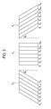
- FIG. 3 is a schematic diagram showing an example of a plurality of steering angles and the plurality of ultrasound images corresponding to the plurality of steering angles.
- the Tx signal generating section 210 may generate first Tx signals for obtaining a first ultrasound image F 1 , where the scan-lines S 1 to S N are not steered, second Tx signals for obtaining a second ultrasound image F 2 , where the scan-lines S 1 to S N are electronically steered at a steering angle ⁇ 1 , and third Tx signals for obtaining a third ultrasound image F 3 , where the scan-lines S 1 to S N are electronically steered at a steering angle ⁇ 2 .
- the ultrasound probe 220 may include a plurality of elements (not shown) for reciprocally converting between ultrasound signals and electrical signals.
- the ultrasound probe 220 may be configured to transmit ultrasound signals into the target object in response to the Tx signals provided from the Tx signal generating section 210.
- the ultrasound probe 220 may further receive ultrasound echo signals reflected from the target object to thereby form received signals.
- the received signals may be analog signals.
- the ultrasound probe 220 may transmit ultrasound signals to the target object in response to the first Tx signals provided from the Tx signal generation section 210.
- the ultrasound probe 220 may further receive ultrasound echo signals reflected from the target object to thereby form first received signals.
- the ultrasound probe 220 may further transmit ultrasound signals to the target object in response to the second Tx signals provided from the Tx signal generation section 210.
- the ultrasound probe 220 may receive ultrasound echo signals reflected from the target object to thereby form second received signals.
- the ultrasound probe 220 may further transmit ultrasound signals to the target object in response to the third Tx signals provided from the Tx signal generation section 210.
- the ultrasound probe 220 may further receive ultrasound echo signals reflected from the target object to thereby form third received signals.
- the beam former 230 may be configured to convert the received signals into digital signals.
- the beam former 230 may further apply delays to the digital signals in consideration of focal points and distance between the elements to thereby form digital receive-focused signals.
- the beam former 230 may convert the first received signals provided from the ultrasound probe 220 into first digital signals.
- the beam former 230 may further apply delays to the first digital signals in consideration of focal points and distance between the elements to thereby form first digital receive-focused signals.
- the beam former 230 may further convert the second received signals provided from the ultrasound probe 220 into second digital signals.
- the beam former 230 may further apply delays to the second digital signals in consideration of focal points and distance between the elements to thereby form second digital receive-focused signals.
- the beam former 230 may further convert the third received signals provided from the ultrasound probe 220 into third digital signals.
- the beam former 230 may further apply delays to the third digital signals in consideration of focal points and distance between the elements to thereby form third digital receive-focused signals.
- the ultrasound data forming section 240 may be configured to form ultrasound data based on the digital receive-focused signals provided from the beam former 230.
- the ultrasound data forming section 240 may further perform signal processing (e.g., gain control, etc) upon the digital receive-focused signals.
- the ultrasound data forming section 240 may form first ultrasound data corresponding to the first ultrasound image F 1 as shown in FIG. 3 based on the first digital receive-focused signals provided from the beam former 230.
- the ultrasound data forming section 240 may further form second ultrasound data corresponding to the second ultrasound image F 2 as shown in FIG. 3 based on the second digital receive-focused signals provided from the beam former 230.
- the ultrasound data forming section 240 may further form third ultrasound data corresponding to the third ultrasound image F 3 as shown in FIG. 3 based on the third digital receive-focused signals provided from the beam former 230.
- the ultrasound system 100 may further include a processing unit 120 in communication with the ultrasound data acquisition unit 110.
- FIG. 4 is a flow chart showing a process of forming an ultrasound spatial compound image.
- the processing unit 120 as shown in FIG. 1 , may be configured to form the plurality of ultrasound images based on the plurality of ultrasound data provided from the ultrasound data acquisition unit 110, at step S402.
- the processing unit 120 may form the first ultrasound image F 1 as shown in FIG. 3 based on the first ultrasound data provided from the ultrasound data acquisition unit 110.
- the processing unit 120 may further form the second ultrasound image F 2 as shown in FIG. 3 based on the second ultrasound data provided from the ultrasound data acquisition unit 110.
- the processing unit 120 may further form a third ultrasound image F 3 as shown in FIG. 3 based on the third ultrasound data provided from the ultrasound data acquisition unit 110.
- the processing unit 120 may be configured to decompose each of the ultrasound images into a low pass image having a low frequency component and a high pass image having a high frequency component, at step S404.
- FIG. 5 is a schematic diagram showing an example of decomposing an ultrasound image into an N (N ⁇ 2)-level low pass image and an N-level high pass image.
- the processing unit 120 may decompose each of the ultrasound images I into a first-level low pass image I L and a first-level high pass image I H by using a first low pass filter.
- the processing unit 120 may further decompose the first-level low pass image I L into a second-level low pass image I LL and a second-level high pass image I LH by using a second low pass filter.
- a cutoff frequency of the second low pass filter is lower than that of the first low pass filter.
- the processing unit 120 may further decompose the second-level low pass image I LL into a third-level low pass image I LLL and a third-level high pass image I LLH by using a third low pass filter.
- the cutoff frequency of the third low pass filter is lower than that of the second low pass filter.
- the processing unit 120 may be configured to perform a blending process upon the decomposed low pass image and high pass image for each of the ultrasound, at step S406.
- the blending process may include an alpha-blending process. However, it should be noted herein that the blending process may be not limited thereto.
- the processing unit 120 may detect boundary lines of the low pass images corresponding to the plurality of ultrasound images.
- the processing unit 120 may detect boundary lines of the high pass images corresponding to the plurality of ultrasound images.
- the processing unit 120 may further set blending areas having a predetermined size on the low pass images and the high pass images based on the detected boundary lines.
- the processing unit 120 may further perform the blending process upon the low pass images and the high pass images based on the blending areas.
- the processing unit 120 may detect a boundary line L 1 of the low pass image I L1 corresponding to the first ultrasound image F 1 as shown in FIG. 3 and the low pass image I L2 corresponding to the second ultrasound image F 2 as shown in FIG. 3 .
- the processing unit 120 may further set a blending area D 1 having the predetermined size on the low pass image I L1 and the low pass image I L2 based on the boundary line L 1 .
- the area NA 12 may be a non-overlapped area of the low pass image I L1 and the low pass image I L2 .
- the area CA 12 may be an overlapped area of the low pass image I L1 and the low pass image I L2 .
- the weight value, which may be applied to the blending area D 1 may vary from al to a2, as going from a boundary of the area NA 12 and the blending area D 1 and a boundary of the area CA 12 and the blending area D 1 .
- the processing unit 120 may further detect a boundary line L 2 of the low pass image I L1 corresponding to the first ultrasound image F 1 as shown in FIG. 3 and the low pass image I L3 corresponding to the third ultrasound image F 3 as shown in FIG. 3 .
- the processing unit 120 may further set a blending area D 2 having the predetermined size on the low pass image I L1 and the low pass image I L3 based on the boundary line L 2 .
- the area NA 13 may be a non-overlapped area of the low pass image I L1 and the low pass image I L3 .
- the area CA 13 may be an overlapped area of the low pass image I L1 and the low pass image I L3 .
- the processing unit 120 may perform the blending process upon the high pass images corresponding to the ultrasound images F 1 to F 3 as mentioned above.
- the processing unit 120 may be configured to compose the blended low pass images and high pass images to thereby form a plurality of restoration images corresponding to the plurality of ultrasound images at step S408 in FIG. 4 .
- the processing unit 120 may compose the blended low pass image and high pass image corresponding to the first ultrasound image F 1 as shown in FIG. 3 to thereby form a first restoration image corresponding to the first ultrasound image F 1.
- the processing unit 120 may further compose the blended low pass image and high pass image corresponding to the second ultrasound image F 2 as shown in FIG. 3 to thereby form a second restoration image corresponding to the second ultrasound image F 2 .
- the processing unit 120 may further compose the blended low pass image and high pass image corresponding to the third ultrasound image F 3 as shown in FIG. 3 to thereby form a third restoration image corresponding to the third ultrasound image F 3 .
- the processing unit 120 may be configured to perform a spatial compound imaging upon the plurality of restoration images to thereby form an ultrasound spatial compound image at step S410.
- the methods of performing the spatial compound imaging are well known in the art. Thus, they have not been described in detail so as not to unnecessarily obscure the present invention.
- the processing unit 120 may perform the spatial compound imaging upon the first restoration image, the second restoration image and the third restoration image to thereby form the ultrasound spatial compound image.
- the ultrasound system may further include a storage unit 130.
- the storage unit 130 may store the ultrasound data acquired by the ultrasound data acquisition unit 110.
- the storage unit 130 may further store the plurality of ultrasound images formed by the processing unit 120.
- the ultrasound system may further include a display unit 140.
- the display unit 140 may display the ultrasound spatial compound image formed by the processing unit 120.
- the display unit 140 may further display the plurality of ultrasound images formed by the processing unit 120.
Landscapes
- Engineering & Computer Science (AREA)
- Physics & Mathematics (AREA)
- Remote Sensing (AREA)
- Radar, Positioning & Navigation (AREA)
- General Physics & Mathematics (AREA)
- Acoustics & Sound (AREA)
- Theoretical Computer Science (AREA)
- Health & Medical Sciences (AREA)
- Life Sciences & Earth Sciences (AREA)
- Computer Networks & Wireless Communication (AREA)
- Nuclear Medicine, Radiotherapy & Molecular Imaging (AREA)
- Biomedical Technology (AREA)
- Medical Informatics (AREA)
- Molecular Biology (AREA)
- Surgery (AREA)
- Animal Behavior & Ethology (AREA)
- General Health & Medical Sciences (AREA)
- Public Health (AREA)
- Veterinary Medicine (AREA)
- Heart & Thoracic Surgery (AREA)
- Radiology & Medical Imaging (AREA)
- Pathology (AREA)
- Biophysics (AREA)
- Computer Graphics (AREA)
- Geometry (AREA)
- Software Systems (AREA)
- Ultra Sonic Daignosis Equipment (AREA)
- Image Processing (AREA)
Abstract
Description
- The present disclosure generally relates to ultrasound systems, and more particularly to providing an ultrasound spatial compound image in an ultrasound system.
- An ultrasound system has become an important and popular diagnostic tool since it has a wide range of applications. Specifically, due to its non-invasive and non-destructive nature, the ultrasound system has been extensively used in the medical profession. Modem high-performance ultrasound systems and techniques are commonly used to produce two or three-dimensional diagnostic images of internal features of an object (e.g., human organs).
- The ultrasound system transmits and receives ultrasound signals to and from a target object to thereby form a 2D (two-dimensional) ultrasound image or a 3D (three-dimensional) ultrasound image. Various techniques have been studied to enhance resolution of the ultrasound image. Spatial compounding is known as one of such techniques.
- The spatial compounding is an imaging technique for forming a single compounding image by combining ultrasound images obtained from multiple points and angles. That is, the ultrasound system electronically steers scan-lines at different steering angles to thereby form a plurality of ultrasound images. The ultrasound system may then compound the ultrasound image to form an ultrasound spatial compound image. Border lines of the ultrasound images are represented on the ultrasound spatial compound image. That is, a seam artifact occurs when the ultrasound spatial compound image is formed by compounding the ultrasound images. Thus, there is a problem in that the quality of the ultrasound spatial compound image becomes poor.
- Embodiments for providing a plurality of slice images in an ultrasound system are disclosed herein. In one embodiment, by way of non-limiting example, an ultrasound system comprises: an ultrasound data acquisition unit configured to transmit and receive ultrasound signals to and from a target object based on a plurality of steering angles to thereby output a plurality of ultrasound data for obtaining a plurality of ultrasound images corresponding to the plurality of steering angles; and a processing unit in communication with the ultrasound data acquisition unit, the processing unit being configured to form the plurality of ultrasound images based on the plurality of ultrasound data, decompose each of the ultrasound images into a low pass image having a low frequency component and a high pass image having a high frequency component, perform a blending process for removing a seam artifact upon the low pass image and the high pass image for each of the ultrasound images, form a plurality of restoration images by composing the blended low pass image and the high pass image, and form an ultrasound spatial compound image based on the plurality of restoration images.
- In another embodiment, there is provided a method of providing an ultrasound spatial compound image comprising: a) forming a plurality of ultrasound images based on a plurality of ultrasound data, wherein the plurality of ultrasound images correspond to a plurality of steering angles; b) decomposing each of the ultrasound images into a low pass image having a low frequency component and a high pass image having a high frequency component; c) performing a blending process of removing a seam artifact upon the low pass image and the high pass image for each of the ultrasound images; d) forming a plurality of restoration images by composing the blended low pass image and the high pass image; and e) forming an ultrasound spatial compound image based on the plurality of restoration images.
- The Summary is provided to introduce a selection of concepts in a simplified form that are further described below in the Detailed Description. This Summary is not intended to identify key or essential features of the claimed subject matter, nor is it intended to be used in determining the scope of the claimed subject matter.
-
- FIG. 1
- is a block diagram showing an illustrative embodiment of an ultrasound system.
- FIG. 2
- is a block diagram showing an illustrative embodiment of an ultrasound data acquisition unit.
- FIG. 3
- is a schematic diagram showing an example of a plurality of steering angles and a plurality of ultrasound images corresponding to the plurality of steering angles.
- FIG. 4
- is a flow chart showing a process of forming an ultrasound spatial compound image.
- FIG. 5
- is a schematic diagram showing an example of decomposing an ultrasound image into an N-level low pass image and an N-level high pass image.
- FIG. 6
- is a schematic diagram showing an example of a plurality of low pass images corresponding to the plurality of ultrasound images, boundary areas and blending areas.
- A detailed description may be provided with reference to the accompanying drawings. One of ordinary skill in the art may realize that the following description is illustrative only and is not in any way limiting.
- Referring to
FIG. 1 , anultrasound system 100 in accordance with an illustrative embodiment is shown. As depicted therein, theultrasound system 100 may include an ultrasounddata acquisition unit 110. The ultrasounddata acquisition unit 110 may be configured to transmit and receive ultrasound signals to and from a target object to thereby output ultrasound data. -
FIG. 2 is a block diagram showing an illustrative embodiment of the ultrasounddata acquisition unit 110. Referring toFIG. 2 , the ultrasounddata acquisition unit 110 may include a transmit (Tx) signal generatingsection 210, anultrasound probe 220, a beam former 230 and an ultrasounddata forming section 240. - The Tx
signal generating section 210 may be configured to generate Tx signals. In one embodiment, the Txsignal generating section 210 may generate a plurality of Tx signals with different Tx patterns such that scan-lines are steered at different steering angles. Thus, a plurality of ultrasound images corresponding to the respective steering angles may be obtained. The ultrasound image may include a brightness mode (B mode) image. However, it should be noted herein that the ultrasound image may not be limited thereto. -
FIG. 3 is a schematic diagram showing an example of a plurality of steering angles and the plurality of ultrasound images corresponding to the plurality of steering angles. Referring toFIG 3 , the Txsignal generating section 210, as shown inFIG. 2 , may generate first Tx signals for obtaining a first ultrasound image F1, where the scan-lines S1 to SN are not steered, second Tx signals for obtaining a second ultrasound image F2, where the scan-lines S1 to SN are electronically steered at a steering angle θ1, and third Tx signals for obtaining a third ultrasound image F3, where the scan-lines S1 to SN are electronically steered at a steering angle θ2. - Referring back to
FIG. 2 , theultrasound probe 220 may include a plurality of elements (not shown) for reciprocally converting between ultrasound signals and electrical signals. Theultrasound probe 220 may be configured to transmit ultrasound signals into the target object in response to the Tx signals provided from the Txsignal generating section 210. Theultrasound probe 220 may further receive ultrasound echo signals reflected from the target object to thereby form received signals. The received signals may be analog signals. - In one embodiment, the
ultrasound probe 220 may transmit ultrasound signals to the target object in response to the first Tx signals provided from the Txsignal generation section 210. Theultrasound probe 220 may further receive ultrasound echo signals reflected from the target object to thereby form first received signals. Theultrasound probe 220 may further transmit ultrasound signals to the target object in response to the second Tx signals provided from the Txsignal generation section 210. Theultrasound probe 220 may receive ultrasound echo signals reflected from the target object to thereby form second received signals. Theultrasound probe 220 may further transmit ultrasound signals to the target object in response to the third Tx signals provided from the Txsignal generation section 210. Theultrasound probe 220 may further receive ultrasound echo signals reflected from the target object to thereby form third received signals. - The beam former 230 may be configured to convert the received signals into digital signals. The beam former 230 may further apply delays to the digital signals in consideration of focal points and distance between the elements to thereby form digital receive-focused signals.
- In one embodiment, the beam former 230 may convert the first received signals provided from the
ultrasound probe 220 into first digital signals. The beam former 230 may further apply delays to the first digital signals in consideration of focal points and distance between the elements to thereby form first digital receive-focused signals. The beam former 230 may further convert the second received signals provided from theultrasound probe 220 into second digital signals. The beam former 230 may further apply delays to the second digital signals in consideration of focal points and distance between the elements to thereby form second digital receive-focused signals. The beam former 230 may further convert the third received signals provided from theultrasound probe 220 into third digital signals. The beam former 230 may further apply delays to the third digital signals in consideration of focal points and distance between the elements to thereby form third digital receive-focused signals. - The ultrasound
data forming section 240 may be configured to form ultrasound data based on the digital receive-focused signals provided from the beam former 230. The ultrasounddata forming section 240 may further perform signal processing (e.g., gain control, etc) upon the digital receive-focused signals. - In one embodiment, the ultrasound
data forming section 240 may form first ultrasound data corresponding to the first ultrasound image F1 as shown inFIG. 3 based on the first digital receive-focused signals provided from the beam former 230. The ultrasounddata forming section 240 may further form second ultrasound data corresponding to the second ultrasound image F2 as shown inFIG. 3 based on the second digital receive-focused signals provided from the beam former 230. The ultrasounddata forming section 240 may further form third ultrasound data corresponding to the third ultrasound image F3 as shown inFIG. 3 based on the third digital receive-focused signals provided from the beam former 230. - Referring back to
FIG. 1 , theultrasound system 100 may further include aprocessing unit 120 in communication with the ultrasounddata acquisition unit 110. -
FIG. 4 is a flow chart showing a process of forming an ultrasound spatial compound image. Theprocessing unit 120, as shown inFIG. 1 , may be configured to form the plurality of ultrasound images based on the plurality of ultrasound data provided from the ultrasounddata acquisition unit 110, at step S402. - In one embodiment, the
processing unit 120 may form the first ultrasound image F1 as shown inFIG. 3 based on the first ultrasound data provided from the ultrasounddata acquisition unit 110. Theprocessing unit 120 may further form the second ultrasound image F2 as shown inFIG. 3 based on the second ultrasound data provided from the ultrasounddata acquisition unit 110. Theprocessing unit 120 may further form a third ultrasound image F3 as shown inFIG. 3 based on the third ultrasound data provided from the ultrasounddata acquisition unit 110. - The
processing unit 120 may be configured to decompose each of the ultrasound images into a low pass image having a low frequency component and a high pass image having a high frequency component, at step S404. - The
processing unit 120 may decompose each of the ultrasound images into the low pass image and the high pass image by using a low pass filter as following equation.
I represents the ultrasound image, IL represents the low pass image, IH represents the high pass image, *epresents convolution, and G represents the low pass filter. The low pass filter may include two-dimensional Gaussian filter. However, it should be noted herein that the low pass filter may be not limited thereto. -
FIG. 5 is a schematic diagram showing an example of decomposing an ultrasound image into an N (N≥2)-level low pass image and an N-level high pass image. In another embodiment, theprocessing unit 120 may decompose each of the ultrasound images I into a first-level low pass image IL and a first-level high pass image IH by using a first low pass filter. Theprocessing unit 120 may further decompose the first-level low pass image IL into a second-level low pass image ILL and a second-level high pass image ILH by using a second low pass filter. A cutoff frequency of the second low pass filter is lower than that of the first low pass filter. Theprocessing unit 120 may further decompose the second-level low pass image ILL into a third-level low pass image ILLL and a third-level high pass image ILLH by using a third low pass filter. The cutoff frequency of the third low pass filter is lower than that of the second low pass filter. - Referring back to
FIG. 4 , theprocessing unit 120 may be configured to perform a blending process upon the decomposed low pass image and high pass image for each of the ultrasound, at step S406. The blending process may include an alpha-blending process. However, it should be noted herein that the blending process may be not limited thereto. - More particularly, the
processing unit 120 may detect boundary lines of the low pass images corresponding to the plurality of ultrasound images. Theprocessing unit 120 may detect boundary lines of the high pass images corresponding to the plurality of ultrasound images. Theprocessing unit 120 may further set blending areas having a predetermined size on the low pass images and the high pass images based on the detected boundary lines. Theprocessing unit 120 may further perform the blending process upon the low pass images and the high pass images based on the blending areas. - Referring to
FIG 6 , theprocessing unit 120 may detect a boundary line L1 of the low pass image IL1 corresponding to the first ultrasound image F1 as shown inFIG. 3 and the low pass image IL2 corresponding to the second ultrasound image F2 as shown inFIG. 3 . Theprocessing unit 120 may further set a blending area D1 having the predetermined size on the low pass image IL1 and the low pass image IL2 based on the boundary line L1. Theprocessing unit 120 may further perform the blending process upon the low pass image IL1 and the low pass image IL2 for applying a first weight value al to pixels of the blending area D1 adjacent to an area NA12 and applying a second weight value (a2 = 1-a1) to pixels of the blending area D1 adjacent to an area CA12. The area NA12 may be a non-overlapped area of the low pass image IL1 and the low pass image IL2. In addition, the area CA12 may be an overlapped area of the low pass image IL1 and the low pass image IL2. That is, the weight value, which may be applied to the blending area D1, may vary from al to a2, as going from a boundary of the area NA12 and the blending area D1 and a boundary of the area CA12 and the blending area D1. As shown inFIG. 6 , theprocessing unit 120 may further detect a boundary line L2 of the low pass image IL1 corresponding to the first ultrasound image F1 as shown inFIG. 3 and the low pass image IL3 corresponding to the third ultrasound image F3 as shown inFIG. 3 . Theprocessing unit 120 may further set a blending area D2 having the predetermined size on the low pass image IL1 and the low pass image IL3 based on the boundary line L2. Theprocessing unit 120 may further the blending process upon the low pass image IL1 and the low pass image IL3 for applying the first weight value a1 to pixels of the blending area D2 adjacent to an area NA13 and applying the second weight value (a2 = 1-a1) to pixels of the blending area D2 adjacent to an area CA13. The area NA13 may be a non-overlapped area of the low pass image IL1 and the low pass image IL3. Further, the area CA13 may be an overlapped area of the low pass image IL1 and the low pass image IL3. Theprocessing unit 120 may perform the blending process upon the high pass images corresponding to the ultrasound images F1 to F3 as mentioned above. - The
processing unit 120 may be configured to compose the blended low pass images and high pass images to thereby form a plurality of restoration images corresponding to the plurality of ultrasound images at step S408 inFIG. 4 . - In one embodiment, the
processing unit 120 may compose the blended low pass image and high pass image corresponding to the first ultrasound image F1 as shown inFIG. 3 to thereby form a first restoration image corresponding to the first ultrasound image F1. Theprocessing unit 120 may further compose the blended low pass image and high pass image corresponding to the second ultrasound image F2 as shown inFIG. 3 to thereby form a second restoration image corresponding to the second ultrasound image F2. Theprocessing unit 120 may further compose the blended low pass image and high pass image corresponding to the third ultrasound image F3 as shown inFIG. 3 to thereby form a third restoration image corresponding to the third ultrasound image F3. - The
processing unit 120 may be configured to perform a spatial compound imaging upon the plurality of restoration images to thereby form an ultrasound spatial compound image at step S410. The methods of performing the spatial compound imaging are well known in the art. Thus, they have not been described in detail so as not to unnecessarily obscure the present invention. In one embodiment, theprocessing unit 120 may perform the spatial compound imaging upon the first restoration image, the second restoration image and the third restoration image to thereby form the ultrasound spatial compound image. - Referring back to
FIG. 1 , the ultrasound system may further include astorage unit 130. Thestorage unit 130 may store the ultrasound data acquired by the ultrasounddata acquisition unit 110. Thestorage unit 130 may further store the plurality of ultrasound images formed by theprocessing unit 120. - The ultrasound system may further include a
display unit 140. Thedisplay unit 140 may display the ultrasound spatial compound image formed by theprocessing unit 120. Thedisplay unit 140 may further display the plurality of ultrasound images formed by theprocessing unit 120. - Although embodiments have been described with reference to a number of illustrative embodiments thereof, it should be understood that numerous other modifications and embodiments can be devised by those skilled in the art that will fall within the scope of the principles of this disclosure. More particularly, numerous variations and modifications are possible in the component parts and/or arrangements of the subject combination arrangement within the scope of the disclosure, the drawings and the appended claims. In addition to variations and modifications in the component parts and/or arrangements, alternative uses will also be apparent to those skilled in the art.
Claims (10)
- An ultrasound system, comprising:an ultrasound data acquisition unit configured to transmit and receive ultrasound signals to and from a target object based on a plurality of steering angles to thereby output a plurality of ultrasound data for obtaining a plurality of ultrasound images corresponding to the steering angles; anda processing unit in communication with the ultrasound data acquisition unit, the processing unit being configured to form the ultrasound images based on the ultrasound data, decompose each of the ultrasound images into a low pass image having a low frequency component and a high pass image having a high frequency component, perform a blending process to remove a seam artifact upon the low pass image and the high pass image for each of the ultrasound images, form a plurality of restoration images by composing the blended low pass image and the high pass image, and form an ultrasound spatial compound image based on the restoration images.
- The ultrasound system of Claim 1, wherein the processing unit is configured to decompose each of the ultrasound images into the low pass image and the high pass image by using a low pass filter.
- The ultrasound system of Claim 1, wherein the processing unit is configured to:detect first boundary lines of the low pass images and second boundary lines of the high pass images;set first blending areas having a predetermined size on the low pass images based on the first boundary lines and second blending areas having the predetermined size on the high pass images based on the second boundary lines; andperform the blending process upon the low pass images and the high pass images based on the first blending areas and the second blending areas.
- The ultrasound system of Claim 3, wherein the processing unit is configured to perform the blending process for applying a first weight value to pixels of the first blending areas adjacent to a non-overlapped area of the low pass images, applying a second weight value to pixels of the first blending areas adjacent to a overlapped area of the low pass images, applying the first weight value to pixels of the second blending areas adjacent to a non-overlapped area of the high pass images, and applying the second weight value to pixels of the second blending areas adjacent to a overlapped area of the high pass images.
- The ultrasound system of Claim 1, wherein the blending process comprises an alpha blending process.
- A method of providing an ultrasound spatial compound image, comprising:a) forming a plurality of ultrasound images based on a plurality of ultrasound data, wherein the ultrasound images correspond to a plurality of steering angles;b) decomposing each of the ultrasound images into a low pass image having a low frequency component and a high pass image having a high frequency component;c) performing a blending process to remove a seam artifact upon the low pass image and the high pass image for each of the ultrasound images;d) forming a plurality of restoration images by composing the blended low pass image and the high pass image; ande) forming an ultrasound spatial compound image based on the restoration images.
- The method of Claim 6, wherein the step b) comprises decomposing each of the ultrasound images by using a low pass filter.
- The method of Claim 6, wherein the step c) comprises:c1) detecting first boundary lines of the low pass images and second boundary lines of the high pass images;c2) setting first blending areas on the low pass images based on the first boundary lines and second blending areas on the high pass images based on the second boundary lines; andc3) performing the blending process upon the low pass images and the high pass images based on the first blending areas and the second blending areas.
- The method of Claim 8, wherein the step c3) comprises:applying a first weight value to pixels of the first blending areas adjacent to a non-overlapped area of the low pass imagesapplying a second weight value to pixels of the first blending areas adjacent to a overlapped area of the low pass imagesapplying the first weight value to pixels of the second blending areas adjacent to a non-overlapped area of the high pass images; andapplying the second weight value to pixels of the second blending areas adjacent to a overlapped area of the high pass images.
- The method of Claim 6, wherein the blending process comprises an alpha blending process.
Applications Claiming Priority (1)
| Application Number | Priority Date | Filing Date | Title |
|---|---|---|---|
| KR1020090111747A KR101120820B1 (en) | 2009-11-19 | 2009-11-19 | Ultrasound system and method for providing ultrasound spatial compound image |
Publications (3)
| Publication Number | Publication Date |
|---|---|
| EP2327998A2 true EP2327998A2 (en) | 2011-06-01 |
| EP2327998A3 EP2327998A3 (en) | 2013-08-07 |
| EP2327998B1 EP2327998B1 (en) | 2017-11-01 |
Family
ID=43733949
Family Applications (1)
| Application Number | Title | Priority Date | Filing Date |
|---|---|---|---|
| EP10175431.5A Not-in-force EP2327998B1 (en) | 2009-11-19 | 2010-09-06 | Providing an ultrasound spatial compound image in an ultrasound system |
Country Status (4)
| Country | Link |
|---|---|
| US (1) | US8727990B2 (en) |
| EP (1) | EP2327998B1 (en) |
| JP (1) | JP5564406B2 (en) |
| KR (1) | KR101120820B1 (en) |
Families Citing this family (7)
| Publication number | Priority date | Publication date | Assignee | Title |
|---|---|---|---|---|
| JP5272084B2 (en) * | 2012-01-11 | 2013-08-28 | 日立アロカメディカル株式会社 | Ultrasonic diagnostic equipment |
| KR102070262B1 (en) * | 2012-11-29 | 2020-03-02 | 삼성전자주식회사 | Ultrasonic Probe apparatus and Method for controlling Ultrasonic Probe apparatus thereof |
| KR20150050728A (en) | 2013-10-31 | 2015-05-11 | 삼성전자주식회사 | Ultrasound imaging apparatus and control method for the same |
| US9629553B2 (en) * | 2014-12-19 | 2017-04-25 | Volcano Corporation | Seam elimination and motion compensation in imaging data |
| CN108460754B (en) * | 2018-01-15 | 2020-08-18 | 浙江深博医疗技术有限公司 | Method for converting low-frequency ultrasonic image into high-frequency ultrasonic image |
| WO2020053040A1 (en) | 2018-09-10 | 2020-03-19 | Koninklijke Philips N.V. | Grating lobes reduction for ultrasound images and associated devices, systems, and methods |
| KR20210066494A (en) * | 2019-11-28 | 2021-06-07 | 주식회사 지이모션 | Method for 3d modeling of clothing |
Family Cites Families (19)
| Publication number | Priority date | Publication date | Assignee | Title |
|---|---|---|---|---|
| US5879303A (en) * | 1996-09-27 | 1999-03-09 | Atl Ultrasound | Ultrasonic diagnostic imaging of response frequency differing from transmit frequency |
| JP4382884B2 (en) | 1996-11-08 | 2009-12-16 | コーニンクレッカ フィリップス エレクトロニクス エヌ ヴィ | Ultrasonic image processing method and apparatus using harmonics |
| US6458083B1 (en) * | 1996-11-26 | 2002-10-01 | Koninklijke Philips Electronics N.V. | Ultrasonic harmonic imaging with adaptive image formation |
| US6511426B1 (en) * | 1998-06-02 | 2003-01-28 | Acuson Corporation | Medical diagnostic ultrasound system and method for versatile processing |
| US6224552B1 (en) | 1998-10-01 | 2001-05-01 | Atl Ultrasound | Ultrasonic diagnostic imaging system with reduced spatial compounding seam artifacts |
| US6210328B1 (en) | 1998-10-01 | 2001-04-03 | Atl Ultrasound | Ultrasonic diagnostic imaging system with variable spatial compounding |
| US6554770B1 (en) * | 1998-11-20 | 2003-04-29 | Acuson Corporation | Medical diagnostic ultrasound imaging methods for extended field of view |
| US6364835B1 (en) * | 1998-11-20 | 2002-04-02 | Acuson Corporation | Medical diagnostic ultrasound imaging methods for extended field of view |
| JP3688561B2 (en) | 2000-06-30 | 2005-08-31 | アロカ株式会社 | Ultrasonic diagnostic equipment |
| US6527720B1 (en) * | 2001-09-24 | 2003-03-04 | Acuson Corporation | Medical ultrasonic imaging method and system for spatial compounding |
| JP2004290393A (en) | 2003-03-26 | 2004-10-21 | Matsushita Electric Ind Co Ltd | Ultrasound diagnostic equipment |
| JP4691934B2 (en) * | 2003-09-25 | 2011-06-01 | 宇部興産株式会社 | High molecular weight polyoxalate resin and method for producing the same |
| US9237929B2 (en) * | 2003-12-22 | 2016-01-19 | Koninklijke Philips N.V. | System for guiding a medical instrument in a patient body |
| EP1757954A3 (en) * | 2005-08-22 | 2008-06-04 | Medison Co., Ltd. | System and method of forming an ultrasound spatial compound image |
| JP2007236740A (en) | 2006-03-10 | 2007-09-20 | Toshiba Corp | Ultrasonic diagnostic apparatus and control program therefor |
| KR100923026B1 (en) * | 2006-09-19 | 2009-10-22 | 주식회사 메디슨 | Ultrasound System and Method for Forming Ultrasound Images |
| JP5627890B2 (en) | 2006-11-03 | 2014-11-19 | コーニンクレッカ フィリップス エヌ ヴェ | Dual path processing for optimal speckle tracking |
| JP5002397B2 (en) | 2007-09-28 | 2012-08-15 | 株式会社東芝 | Ultrasonic diagnostic apparatus and program |
| JP5049773B2 (en) | 2007-12-27 | 2012-10-17 | 株式会社東芝 | Ultrasonic diagnostic device, ultrasonic image processing device, ultrasonic image processing program |
-
2009
- 2009-11-19 KR KR1020090111747A patent/KR101120820B1/en not_active Expired - Fee Related
-
2010
- 2010-09-06 EP EP10175431.5A patent/EP2327998B1/en not_active Not-in-force
- 2010-09-15 US US12/882,902 patent/US8727990B2/en active Active
- 2010-11-08 JP JP2010250088A patent/JP5564406B2/en not_active Expired - Fee Related
Non-Patent Citations (1)
| Title |
|---|
| None |
Also Published As
| Publication number | Publication date |
|---|---|
| US20110118604A1 (en) | 2011-05-19 |
| EP2327998A3 (en) | 2013-08-07 |
| KR101120820B1 (en) | 2012-03-22 |
| KR20110054924A (en) | 2011-05-25 |
| JP2011104361A (en) | 2011-06-02 |
| EP2327998B1 (en) | 2017-11-01 |
| JP5564406B2 (en) | 2014-07-30 |
| US8727990B2 (en) | 2014-05-20 |
Similar Documents
| Publication | Publication Date | Title |
|---|---|---|
| US8792690B2 (en) | Enhancing quality of ultrasound spatial compound image based on beam profile in ultrasound system | |
| US9008383B2 (en) | Enhancing quality of ultrasound image in ultrasound system | |
| US8343054B1 (en) | Methods and apparatus for ultrasound imaging | |
| EP2444001A1 (en) | Providing an ultrasound spatial compound image based on a phased array probe in an ultrasound system | |
| US8998812B2 (en) | Ultrasound method and probe for electromagnetic noise cancellation | |
| US8727990B2 (en) | Providing an ultrasound spatial compound image in an ultrasound system | |
| CN106600550B (en) | Ultrasonic image processing method and system | |
| EP2347713B1 (en) | Ultrasound image enhancement in an ultrasound system | |
| US20110118605A1 (en) | Spatial compound imaging in an ultrasound system | |
| WO2012049124A2 (en) | Methods and systems for producing compounded ultrasound images | |
| CN107180414B (en) | System and method for reducing ultrasound speckle using harmonic compounding | |
| CN101396287A (en) | Ultrasound diagnosis apparatus and program | |
| DE102016100367A1 (en) | Sparse tracking in sound beam intensity impulse imaging | |
| DE102016116658A1 (en) | SPARKLEAR FACT RECOGNITION IN ULTRASONIC COLOR FLOW | |
| WO2011052400A1 (en) | Ultrasonic diagnostic device and image construction method | |
| US9151841B2 (en) | Providing an ultrasound spatial compound image based on center lines of ultrasound images in an ultrasound system | |
| CN101088468B (en) | Ultrasonic image acquisition device, image processing device, and ultrasonic image processing method | |
| US8348848B1 (en) | Methods and apparatus for ultrasound imaging | |
| EP2103954B1 (en) | Adaptive clutter signal filtering in an ultrasound system | |
| EP2296004A2 (en) | Ultrasound system and method for providing an ultrasound spatial compound image considering steering angle | |
| US8157735B2 (en) | Ultrasound system and method of providing ultrasound images | |
| US10685439B2 (en) | Imaging system and method providing scalable resolution in multi-dimensional image data | |
| US11331079B2 (en) | Method and device for processing ultrasound signal data | |
| WO2015136534A1 (en) | Strong echoes in ultrasound images | |
| EP3229698B1 (en) | Single-modality-based visual distinguishing of medical intervention device from tissue |
Legal Events
| Date | Code | Title | Description |
|---|---|---|---|
| PUAI | Public reference made under article 153(3) epc to a published international application that has entered the european phase |
Free format text: ORIGINAL CODE: 0009012 |
|
| AK | Designated contracting states |
Kind code of ref document: A2 Designated state(s): AL AT BE BG CH CY CZ DE DK EE ES FI FR GB GR HR HU IE IS IT LI LT LU LV MC MK MT NL NO PL PT RO SE SI SK SM TR |
|
| AX | Request for extension of the european patent |
Extension state: BA ME RS |
|
| PUAL | Search report despatched |
Free format text: ORIGINAL CODE: 0009013 |
|
| AK | Designated contracting states |
Kind code of ref document: A3 Designated state(s): AL AT BE BG CH CY CZ DE DK EE ES FI FR GB GR HR HU IE IS IT LI LT LU LV MC MK MT NL NO PL PT RO SE SI SK SM TR |
|
| AX | Request for extension of the european patent |
Extension state: BA ME RS |
|
| RIC1 | Information provided on ipc code assigned before grant |
Ipc: G01S 15/89 20060101AFI20130701BHEP Ipc: G06T 15/50 20110101ALI20130701BHEP |
|
| 17P | Request for examination filed |
Effective date: 20140206 |
|
| RBV | Designated contracting states (corrected) |
Designated state(s): AL AT BE BG CH CY CZ DE DK EE ES FI FR GB GR HR HU IE IS IT LI LT LU LV MC MK MT NL NO PL PT RO SE SI SK SM TR |
|
| 17Q | First examination report despatched |
Effective date: 20160928 |
|
| GRAP | Despatch of communication of intention to grant a patent |
Free format text: ORIGINAL CODE: EPIDOSNIGR1 |
|
| INTG | Intention to grant announced |
Effective date: 20170518 |
|
| GRAS | Grant fee paid |
Free format text: ORIGINAL CODE: EPIDOSNIGR3 |
|
| RAP1 | Party data changed (applicant data changed or rights of an application transferred) |
Owner name: SAMSUNG MEDISON CO., LTD. |
|
| GRAA | (expected) grant |
Free format text: ORIGINAL CODE: 0009210 |
|
| AK | Designated contracting states |
Kind code of ref document: B1 Designated state(s): AL AT BE BG CH CY CZ DE DK EE ES FI FR GB GR HR HU IE IS IT LI LT LU LV MC MK MT NL NO PL PT RO SE SI SK SM TR |
|
| REG | Reference to a national code |
Ref country code: GB Ref legal event code: FG4D |
|
| REG | Reference to a national code |
Ref country code: CH Ref legal event code: EP Ref country code: AT Ref legal event code: REF Ref document number: 942581 Country of ref document: AT Kind code of ref document: T Effective date: 20171115 |
|
| REG | Reference to a national code |
Ref country code: IE Ref legal event code: FG4D |
|
| REG | Reference to a national code |
Ref country code: DE Ref legal event code: R096 Ref document number: 602010046326 Country of ref document: DE |
|
| REG | Reference to a national code |
Ref country code: NL Ref legal event code: FP |
|
| REG | Reference to a national code |
Ref country code: LT Ref legal event code: MG4D |
|
| REG | Reference to a national code |
Ref country code: AT Ref legal event code: MK05 Ref document number: 942581 Country of ref document: AT Kind code of ref document: T Effective date: 20171101 |
|
| PG25 | Lapsed in a contracting state [announced via postgrant information from national office to epo] |
Ref country code: FI Free format text: LAPSE BECAUSE OF FAILURE TO SUBMIT A TRANSLATION OF THE DESCRIPTION OR TO PAY THE FEE WITHIN THE PRESCRIBED TIME-LIMIT Effective date: 20171101 Ref country code: LT Free format text: LAPSE BECAUSE OF FAILURE TO SUBMIT A TRANSLATION OF THE DESCRIPTION OR TO PAY THE FEE WITHIN THE PRESCRIBED TIME-LIMIT Effective date: 20171101 Ref country code: NO Free format text: LAPSE BECAUSE OF FAILURE TO SUBMIT A TRANSLATION OF THE DESCRIPTION OR TO PAY THE FEE WITHIN THE PRESCRIBED TIME-LIMIT Effective date: 20180201 Ref country code: SE Free format text: LAPSE BECAUSE OF FAILURE TO SUBMIT A TRANSLATION OF THE DESCRIPTION OR TO PAY THE FEE WITHIN THE PRESCRIBED TIME-LIMIT Effective date: 20171101 Ref country code: ES Free format text: LAPSE BECAUSE OF FAILURE TO SUBMIT A TRANSLATION OF THE DESCRIPTION OR TO PAY THE FEE WITHIN THE PRESCRIBED TIME-LIMIT Effective date: 20171101 |
|
| PG25 | Lapsed in a contracting state [announced via postgrant information from national office to epo] |
Ref country code: AT Free format text: LAPSE BECAUSE OF FAILURE TO SUBMIT A TRANSLATION OF THE DESCRIPTION OR TO PAY THE FEE WITHIN THE PRESCRIBED TIME-LIMIT Effective date: 20171101 Ref country code: LV Free format text: LAPSE BECAUSE OF FAILURE TO SUBMIT A TRANSLATION OF THE DESCRIPTION OR TO PAY THE FEE WITHIN THE PRESCRIBED TIME-LIMIT Effective date: 20171101 Ref country code: IS Free format text: LAPSE BECAUSE OF FAILURE TO SUBMIT A TRANSLATION OF THE DESCRIPTION OR TO PAY THE FEE WITHIN THE PRESCRIBED TIME-LIMIT Effective date: 20180301 Ref country code: BG Free format text: LAPSE BECAUSE OF FAILURE TO SUBMIT A TRANSLATION OF THE DESCRIPTION OR TO PAY THE FEE WITHIN THE PRESCRIBED TIME-LIMIT Effective date: 20180201 Ref country code: HR Free format text: LAPSE BECAUSE OF FAILURE TO SUBMIT A TRANSLATION OF THE DESCRIPTION OR TO PAY THE FEE WITHIN THE PRESCRIBED TIME-LIMIT Effective date: 20171101 Ref country code: GR Free format text: LAPSE BECAUSE OF FAILURE TO SUBMIT A TRANSLATION OF THE DESCRIPTION OR TO PAY THE FEE WITHIN THE PRESCRIBED TIME-LIMIT Effective date: 20180202 |
|
| PG25 | Lapsed in a contracting state [announced via postgrant information from national office to epo] |
Ref country code: SK Free format text: LAPSE BECAUSE OF FAILURE TO SUBMIT A TRANSLATION OF THE DESCRIPTION OR TO PAY THE FEE WITHIN THE PRESCRIBED TIME-LIMIT Effective date: 20171101 Ref country code: DK Free format text: LAPSE BECAUSE OF FAILURE TO SUBMIT A TRANSLATION OF THE DESCRIPTION OR TO PAY THE FEE WITHIN THE PRESCRIBED TIME-LIMIT Effective date: 20171101 Ref country code: CY Free format text: LAPSE BECAUSE OF FAILURE TO SUBMIT A TRANSLATION OF THE DESCRIPTION OR TO PAY THE FEE WITHIN THE PRESCRIBED TIME-LIMIT Effective date: 20171101 Ref country code: EE Free format text: LAPSE BECAUSE OF FAILURE TO SUBMIT A TRANSLATION OF THE DESCRIPTION OR TO PAY THE FEE WITHIN THE PRESCRIBED TIME-LIMIT Effective date: 20171101 Ref country code: CZ Free format text: LAPSE BECAUSE OF FAILURE TO SUBMIT A TRANSLATION OF THE DESCRIPTION OR TO PAY THE FEE WITHIN THE PRESCRIBED TIME-LIMIT Effective date: 20171101 |
|
| REG | Reference to a national code |
Ref country code: DE Ref legal event code: R097 Ref document number: 602010046326 Country of ref document: DE |
|
| REG | Reference to a national code |
Ref country code: FR Ref legal event code: PLFP Year of fee payment: 9 |
|
| PG25 | Lapsed in a contracting state [announced via postgrant information from national office to epo] |
Ref country code: PL Free format text: LAPSE BECAUSE OF FAILURE TO SUBMIT A TRANSLATION OF THE DESCRIPTION OR TO PAY THE FEE WITHIN THE PRESCRIBED TIME-LIMIT Effective date: 20171101 Ref country code: SM Free format text: LAPSE BECAUSE OF FAILURE TO SUBMIT A TRANSLATION OF THE DESCRIPTION OR TO PAY THE FEE WITHIN THE PRESCRIBED TIME-LIMIT Effective date: 20171101 Ref country code: RO Free format text: LAPSE BECAUSE OF FAILURE TO SUBMIT A TRANSLATION OF THE DESCRIPTION OR TO PAY THE FEE WITHIN THE PRESCRIBED TIME-LIMIT Effective date: 20171101 |
|
| PLBE | No opposition filed within time limit |
Free format text: ORIGINAL CODE: 0009261 |
|
| STAA | Information on the status of an ep patent application or granted ep patent |
Free format text: STATUS: NO OPPOSITION FILED WITHIN TIME LIMIT |
|
| 26N | No opposition filed |
Effective date: 20180802 |
|
| PG25 | Lapsed in a contracting state [announced via postgrant information from national office to epo] |
Ref country code: SI Free format text: LAPSE BECAUSE OF FAILURE TO SUBMIT A TRANSLATION OF THE DESCRIPTION OR TO PAY THE FEE WITHIN THE PRESCRIBED TIME-LIMIT Effective date: 20171101 |
|
| PG25 | Lapsed in a contracting state [announced via postgrant information from national office to epo] |
Ref country code: MC Free format text: LAPSE BECAUSE OF FAILURE TO SUBMIT A TRANSLATION OF THE DESCRIPTION OR TO PAY THE FEE WITHIN THE PRESCRIBED TIME-LIMIT Effective date: 20171101 |
|
| REG | Reference to a national code |
Ref country code: CH Ref legal event code: PL |
|
| GBPC | Gb: european patent ceased through non-payment of renewal fee |
Effective date: 20180906 |
|
| REG | Reference to a national code |
Ref country code: BE Ref legal event code: MM Effective date: 20180930 |
|
| REG | Reference to a national code |
Ref country code: IE Ref legal event code: MM4A |
|
| PG25 | Lapsed in a contracting state [announced via postgrant information from national office to epo] |
Ref country code: LU Free format text: LAPSE BECAUSE OF NON-PAYMENT OF DUE FEES Effective date: 20180906 |
|
| PG25 | Lapsed in a contracting state [announced via postgrant information from national office to epo] |
Ref country code: IE Free format text: LAPSE BECAUSE OF NON-PAYMENT OF DUE FEES Effective date: 20180906 |
|
| PG25 | Lapsed in a contracting state [announced via postgrant information from national office to epo] |
Ref country code: LI Free format text: LAPSE BECAUSE OF NON-PAYMENT OF DUE FEES Effective date: 20180930 Ref country code: CH Free format text: LAPSE BECAUSE OF NON-PAYMENT OF DUE FEES Effective date: 20180930 Ref country code: BE Free format text: LAPSE BECAUSE OF NON-PAYMENT OF DUE FEES Effective date: 20180930 |
|
| PGFP | Annual fee paid to national office [announced via postgrant information from national office to epo] |
Ref country code: NL Payment date: 20190806 Year of fee payment: 10 |
|
| PG25 | Lapsed in a contracting state [announced via postgrant information from national office to epo] |
Ref country code: GB Free format text: LAPSE BECAUSE OF NON-PAYMENT OF DUE FEES Effective date: 20180906 |
|
| PG25 | Lapsed in a contracting state [announced via postgrant information from national office to epo] |
Ref country code: MT Free format text: LAPSE BECAUSE OF NON-PAYMENT OF DUE FEES Effective date: 20180906 |
|
| PG25 | Lapsed in a contracting state [announced via postgrant information from national office to epo] |
Ref country code: TR Free format text: LAPSE BECAUSE OF FAILURE TO SUBMIT A TRANSLATION OF THE DESCRIPTION OR TO PAY THE FEE WITHIN THE PRESCRIBED TIME-LIMIT Effective date: 20171101 |
|
| PG25 | Lapsed in a contracting state [announced via postgrant information from national office to epo] |
Ref country code: PT Free format text: LAPSE BECAUSE OF FAILURE TO SUBMIT A TRANSLATION OF THE DESCRIPTION OR TO PAY THE FEE WITHIN THE PRESCRIBED TIME-LIMIT Effective date: 20171101 Ref country code: HU Free format text: LAPSE BECAUSE OF FAILURE TO SUBMIT A TRANSLATION OF THE DESCRIPTION OR TO PAY THE FEE WITHIN THE PRESCRIBED TIME-LIMIT; INVALID AB INITIO Effective date: 20100906 |
|
| PG25 | Lapsed in a contracting state [announced via postgrant information from national office to epo] |
Ref country code: MK Free format text: LAPSE BECAUSE OF NON-PAYMENT OF DUE FEES Effective date: 20171101 |
|
| PG25 | Lapsed in a contracting state [announced via postgrant information from national office to epo] |
Ref country code: AL Free format text: LAPSE BECAUSE OF FAILURE TO SUBMIT A TRANSLATION OF THE DESCRIPTION OR TO PAY THE FEE WITHIN THE PRESCRIBED TIME-LIMIT Effective date: 20171101 |
|
| REG | Reference to a national code |
Ref country code: NL Ref legal event code: MM Effective date: 20201001 |
|
| PG25 | Lapsed in a contracting state [announced via postgrant information from national office to epo] |
Ref country code: NL Free format text: LAPSE BECAUSE OF NON-PAYMENT OF DUE FEES Effective date: 20201001 |
|
| PGFP | Annual fee paid to national office [announced via postgrant information from national office to epo] |
Ref country code: IT Payment date: 20230808 Year of fee payment: 14 |
|
| PGFP | Annual fee paid to national office [announced via postgrant information from national office to epo] |
Ref country code: FR Payment date: 20230807 Year of fee payment: 14 Ref country code: DE Payment date: 20230807 Year of fee payment: 14 |
|
| REG | Reference to a national code |
Ref country code: DE Ref legal event code: R119 Ref document number: 602010046326 Country of ref document: DE |
|
| PG25 | Lapsed in a contracting state [announced via postgrant information from national office to epo] |
Ref country code: DE Free format text: LAPSE BECAUSE OF NON-PAYMENT OF DUE FEES Effective date: 20250401 |
|
| PG25 | Lapsed in a contracting state [announced via postgrant information from national office to epo] |
Ref country code: IT Free format text: LAPSE BECAUSE OF NON-PAYMENT OF DUE FEES Effective date: 20240906 |
|
| PG25 | Lapsed in a contracting state [announced via postgrant information from national office to epo] |
Ref country code: FR Free format text: LAPSE BECAUSE OF NON-PAYMENT OF DUE FEES Effective date: 20240930 |