EP2327861A2 - Power cutter - Google Patents
Power cutter Download PDFInfo
- Publication number
- EP2327861A2 EP2327861A2 EP11153737A EP11153737A EP2327861A2 EP 2327861 A2 EP2327861 A2 EP 2327861A2 EP 11153737 A EP11153737 A EP 11153737A EP 11153737 A EP11153737 A EP 11153737A EP 2327861 A2 EP2327861 A2 EP 2327861A2
- Authority
- EP
- European Patent Office
- Prior art keywords
- engine
- oil
- passageway
- petrol
- carburettor
- Prior art date
- Legal status (The legal status is an assumption and is not a legal conclusion. Google has not performed a legal analysis and makes no representation as to the accuracy of the status listed.)
- Granted
Links
Images


Classifications
-
- B—PERFORMING OPERATIONS; TRANSPORTING
- B01—PHYSICAL OR CHEMICAL PROCESSES OR APPARATUS IN GENERAL
- B01D—SEPARATION
- B01D46/00—Filters or filtering processes specially modified for separating dispersed particles from gases or vapours
- B01D46/66—Regeneration of the filtering material or filter elements inside the filter
- B01D46/68—Regeneration of the filtering material or filter elements inside the filter by means acting on the cake side involving movement with regard to the filter elements
- B01D46/681—Regeneration of the filtering material or filter elements inside the filter by means acting on the cake side involving movement with regard to the filter elements by scrapers, brushes or the like
-
- F—MECHANICAL ENGINEERING; LIGHTING; HEATING; WEAPONS; BLASTING
- F02—COMBUSTION ENGINES; HOT-GAS OR COMBUSTION-PRODUCT ENGINE PLANTS
- F02M—SUPPLYING COMBUSTION ENGINES IN GENERAL WITH COMBUSTIBLE MIXTURES OR CONSTITUENTS THEREOF
- F02M1/00—Carburettors with means for facilitating engine's starting or its idling below operational temperatures
- F02M1/08—Carburettors with means for facilitating engine's starting or its idling below operational temperatures the means to facilitate starting or idling becoming operative or inoperative automatically
- F02M1/10—Carburettors with means for facilitating engine's starting or its idling below operational temperatures the means to facilitate starting or idling becoming operative or inoperative automatically dependent on engine temperature, e.g. having thermostat
-
- B—PERFORMING OPERATIONS; TRANSPORTING
- B23—MACHINE TOOLS; METAL-WORKING NOT OTHERWISE PROVIDED FOR
- B23D—PLANING; SLOTTING; SHEARING; BROACHING; SAWING; FILING; SCRAPING; LIKE OPERATIONS FOR WORKING METAL BY REMOVING MATERIAL, NOT OTHERWISE PROVIDED FOR
- B23D45/00—Sawing machines or sawing devices with circular saw blades or with friction saw discs
- B23D45/16—Hand-held sawing devices with circular saw blades
-
- B—PERFORMING OPERATIONS; TRANSPORTING
- B24—GRINDING; POLISHING
- B24B—MACHINES, DEVICES, OR PROCESSES FOR GRINDING OR POLISHING; DRESSING OR CONDITIONING OF ABRADING SURFACES; FEEDING OF GRINDING, POLISHING, OR LAPPING AGENTS
- B24B27/00—Other grinding machines or devices
- B24B27/06—Grinders for cutting-off
- B24B27/08—Grinders for cutting-off being portable
-
- B—PERFORMING OPERATIONS; TRANSPORTING
- B27—WORKING OR PRESERVING WOOD OR SIMILAR MATERIAL; NAILING OR STAPLING MACHINES IN GENERAL
- B27B—SAWS FOR WOOD OR SIMILAR MATERIAL; COMPONENTS OR ACCESSORIES THEREFOR
- B27B5/00—Sawing machines working with circular or cylindrical saw blades; Components or equipment therefor
- B27B5/29—Details; Component parts; Accessories
- B27B5/30—Details; Component parts; Accessories for mounting or securing saw blades or saw spindles
- B27B5/32—Devices for securing circular saw blades to the saw spindle
-
- B—PERFORMING OPERATIONS; TRANSPORTING
- B60—VEHICLES IN GENERAL
- B60K—ARRANGEMENT OR MOUNTING OF PROPULSION UNITS OR OF TRANSMISSIONS IN VEHICLES; ARRANGEMENT OR MOUNTING OF PLURAL DIVERSE PRIME-MOVERS IN VEHICLES; AUXILIARY DRIVES FOR VEHICLES; INSTRUMENTATION OR DASHBOARDS FOR VEHICLES; ARRANGEMENTS IN CONNECTION WITH COOLING, AIR INTAKE, GAS EXHAUST OR FUEL SUPPLY OF PROPULSION UNITS IN VEHICLES
- B60K15/00—Arrangement in connection with fuel supply of combustion engines or other fuel consuming energy converters, e.g. fuel cells; Mounting or construction of fuel tanks
- B60K15/03—Fuel tanks
- B60K15/04—Tank inlets
- B60K15/0406—Filler caps for fuel tanks
-
- F—MECHANICAL ENGINEERING; LIGHTING; HEATING; WEAPONS; BLASTING
- F01—MACHINES OR ENGINES IN GENERAL; ENGINE PLANTS IN GENERAL; STEAM ENGINES
- F01M—LUBRICATING OF MACHINES OR ENGINES IN GENERAL; LUBRICATING INTERNAL COMBUSTION ENGINES; CRANKCASE VENTILATING
- F01M1/00—Pressure lubrication
- F01M1/18—Indicating or safety devices
- F01M1/20—Indicating or safety devices concerning lubricant pressure
- F01M1/22—Indicating or safety devices concerning lubricant pressure rendering machines or engines inoperative or idling on pressure failure
- F01M1/26—Indicating or safety devices concerning lubricant pressure rendering machines or engines inoperative or idling on pressure failure acting on engine ignition system
-
- F—MECHANICAL ENGINEERING; LIGHTING; HEATING; WEAPONS; BLASTING
- F01—MACHINES OR ENGINES IN GENERAL; ENGINE PLANTS IN GENERAL; STEAM ENGINES
- F01M—LUBRICATING OF MACHINES OR ENGINES IN GENERAL; LUBRICATING INTERNAL COMBUSTION ENGINES; CRANKCASE VENTILATING
- F01M3/00—Lubrication specially adapted for engines with crankcase compression of fuel-air mixture or for other engines in which lubricant is contained in fuel, combustion air, or fuel-air mixture
-
- F—MECHANICAL ENGINEERING; LIGHTING; HEATING; WEAPONS; BLASTING
- F02—COMBUSTION ENGINES; HOT-GAS OR COMBUSTION-PRODUCT ENGINE PLANTS
- F02B—INTERNAL-COMBUSTION PISTON ENGINES; COMBUSTION ENGINES IN GENERAL
- F02B63/00—Adaptations of engines for driving pumps, hand-held tools or electric generators; Portable combinations of engines with engine-driven devices
- F02B63/02—Adaptations of engines for driving pumps, hand-held tools or electric generators; Portable combinations of engines with engine-driven devices for hand-held tools
-
- F—MECHANICAL ENGINEERING; LIGHTING; HEATING; WEAPONS; BLASTING
- F02—COMBUSTION ENGINES; HOT-GAS OR COMBUSTION-PRODUCT ENGINE PLANTS
- F02M—SUPPLYING COMBUSTION ENGINES IN GENERAL WITH COMBUSTIBLE MIXTURES OR CONSTITUENTS THEREOF
- F02M1/00—Carburettors with means for facilitating engine's starting or its idling below operational temperatures
- F02M1/08—Carburettors with means for facilitating engine's starting or its idling below operational temperatures the means to facilitate starting or idling becoming operative or inoperative automatically
- F02M1/10—Carburettors with means for facilitating engine's starting or its idling below operational temperatures the means to facilitate starting or idling becoming operative or inoperative automatically dependent on engine temperature, e.g. having thermostat
- F02M1/12—Carburettors with means for facilitating engine's starting or its idling below operational temperatures the means to facilitate starting or idling becoming operative or inoperative automatically dependent on engine temperature, e.g. having thermostat with means for electrically heating thermostat
-
- F—MECHANICAL ENGINEERING; LIGHTING; HEATING; WEAPONS; BLASTING
- F02—COMBUSTION ENGINES; HOT-GAS OR COMBUSTION-PRODUCT ENGINE PLANTS
- F02M—SUPPLYING COMBUSTION ENGINES IN GENERAL WITH COMBUSTIBLE MIXTURES OR CONSTITUENTS THEREOF
- F02M31/00—Apparatus for thermally treating combustion-air, fuel, or fuel-air mixture
- F02M31/02—Apparatus for thermally treating combustion-air, fuel, or fuel-air mixture for heating
- F02M31/12—Apparatus for thermally treating combustion-air, fuel, or fuel-air mixture for heating electrically
- F02M31/13—Combustion air
-
- F—MECHANICAL ENGINEERING; LIGHTING; HEATING; WEAPONS; BLASTING
- F02—COMBUSTION ENGINES; HOT-GAS OR COMBUSTION-PRODUCT ENGINE PLANTS
- F02M—SUPPLYING COMBUSTION ENGINES IN GENERAL WITH COMBUSTIBLE MIXTURES OR CONSTITUENTS THEREOF
- F02M35/00—Combustion-air cleaners, air intakes, intake silencers, or induction systems specially adapted for, or arranged on, internal-combustion engines
- F02M35/02—Air cleaners
- F02M35/024—Air cleaners using filters, e.g. moistened
-
- F—MECHANICAL ENGINEERING; LIGHTING; HEATING; WEAPONS; BLASTING
- F02—COMBUSTION ENGINES; HOT-GAS OR COMBUSTION-PRODUCT ENGINE PLANTS
- F02M—SUPPLYING COMBUSTION ENGINES IN GENERAL WITH COMBUSTIBLE MIXTURES OR CONSTITUENTS THEREOF
- F02M35/00—Combustion-air cleaners, air intakes, intake silencers, or induction systems specially adapted for, or arranged on, internal-combustion engines
- F02M35/02—Air cleaners
- F02M35/08—Air cleaners with means for removing dust, particles or liquids from cleaners; with means for indicating clogging; with by-pass means; Regeneration of cleaners
-
- F—MECHANICAL ENGINEERING; LIGHTING; HEATING; WEAPONS; BLASTING
- F02—COMBUSTION ENGINES; HOT-GAS OR COMBUSTION-PRODUCT ENGINE PLANTS
- F02M—SUPPLYING COMBUSTION ENGINES IN GENERAL WITH COMBUSTIBLE MIXTURES OR CONSTITUENTS THEREOF
- F02M35/00—Combustion-air cleaners, air intakes, intake silencers, or induction systems specially adapted for, or arranged on, internal-combustion engines
- F02M35/10—Air intakes; Induction systems
- F02M35/1015—Air intakes; Induction systems characterised by the engine type
- F02M35/1017—Small engines, e.g. for handheld tools, or model engines; Single cylinder engines
-
- F—MECHANICAL ENGINEERING; LIGHTING; HEATING; WEAPONS; BLASTING
- F01—MACHINES OR ENGINES IN GENERAL; ENGINE PLANTS IN GENERAL; STEAM ENGINES
- F01M—LUBRICATING OF MACHINES OR ENGINES IN GENERAL; LUBRICATING INTERNAL COMBUSTION ENGINES; CRANKCASE VENTILATING
- F01M1/00—Pressure lubrication
- F01M1/18—Indicating or safety devices
- F01M1/20—Indicating or safety devices concerning lubricant pressure
- F01M1/22—Indicating or safety devices concerning lubricant pressure rendering machines or engines inoperative or idling on pressure failure
-
- Y—GENERAL TAGGING OF NEW TECHNOLOGICAL DEVELOPMENTS; GENERAL TAGGING OF CROSS-SECTIONAL TECHNOLOGIES SPANNING OVER SEVERAL SECTIONS OF THE IPC; TECHNICAL SUBJECTS COVERED BY FORMER USPC CROSS-REFERENCE ART COLLECTIONS [XRACs] AND DIGESTS
- Y02—TECHNOLOGIES OR APPLICATIONS FOR MITIGATION OR ADAPTATION AGAINST CLIMATE CHANGE
- Y02T—CLIMATE CHANGE MITIGATION TECHNOLOGIES RELATED TO TRANSPORTATION
- Y02T10/00—Road transport of goods or passengers
- Y02T10/10—Internal combustion engine [ICE] based vehicles
- Y02T10/12—Improving ICE efficiencies
Definitions
- the present invention relates to a power cutter.
- a typical power cutter comprises a housing in which is mounted a two stroke internal combustion engine. Attached to the side of the housing is a support arm which extends forward of the housing. Rotatably mounted on the end of the support arm is a cutting blade, usually in the form of a grinding disk.
- the motor is drivingly connected to the cutting blade via a drive belt.
- the rotary output of the engine rotatingly drives the cutting blade via the drive belt.
- the drive belt is driven via a centrifugal clutch which enables the out drive spindle of the engine to disengage from the belt when the engine is running at a slow speed, to allow the engine to continue running, whilst disengaging any drive to the cutting blade to allow the blade to be stationary.
- a petrol tank which provides petrol for the engine via a carburettor.
- An oil tank can also be provided, which provides lubricating oil to mix with the petrol, to lubricate the engine.
- a rear handle for supporting the power cutter, which contains a trigger switch for accelerating the engine upon depressing. Depression of the trigger switch causes more of the aerated petrol/oil mixture to be injected into the engine which in turn causes the speed of the engine to accelerate.
- GB2232913 and W02005/056225 show examples of such power cutters.
- a known problem with all two stokes engines is the lubrication of the crank shaft 114 (using the reference numbers shown in Figure 19 ) and piston 1000. This is due to the fact that the petrol/air mixture first passes through a chamber 18 in the cylinder 120 below the piston 1000 before being forced into the chamber 122 above the piston 16 before being ignited. This prevents the use of lubricating oil being pumped around the crank shaft 114 on the underside of the piston 1000. Therefore, in existing designs of two stoke engines, a mixture of aerated petrol and lubricating oil is burnt within the engine, the oil providing lubrication for the crank shaft 114 and piston 1000 prior to being burnt with the petrol during the combustion cycle.
- a common problem with the use of two stoke engines is that the operator forgets to add the oil to the petrol or adds it in an inconsistent manner, thus resulting in damage to the engine.
- This particularly so for power cutters as often power cutters are often hired out to operators.
- operators are not familiar with using them; they are not in the operators possession for long; the operator does not know who had it previously or how the previous operator used the power cutter; and, as the operator does not own it, has less reason to care for the long term maintenance of the power cutter. Therefore, it is desirable that a mechanism is provided to prevent or limit damage to the two stroke engine of the power cutter to ensure that sufficient lubrication oil is included in the aerated petrol which prior to entering the engine.
- the two stroke engines of power cutters use a carburettor to provide aerated petrol for powering the engine.
- a typical design of such a carburettor is shown in Figure 31 .
- the carburettor comprises a housing 1002 through which is formed an air passageway 1004 through which air can pass in the direction of Arrow Q.
- the air passageway 1004 at its entrance and exit has the same cross sectional area.
- formed part way along the length of the air passageway 1004 is a restriction 1006 which reduces the size of the cross sectional area of the air passageway and which acts as a venturi; the air passageway 1004 narrowing and then expanding as the air passes through it. This causes the rate of flow of air through the narrow section 1008 of the air passageway 1004 to increase.
- Petrol enters the carburettor via an inlet 1010 and fills a first chamber 1012.
- the first chamber 1012 is connected to a second chamber 1014 via a petrol passageway 1016.
- Petrol fills the second chamber 1014 via the petrol passageway 1016.
- An adjustable needle valve 1020 which has a pointed tip and an elongate body, is mounted in the petrol passageway 1016 and which can axially slide within the passage way 1016.
- the petrol passageway 1016 comprises a narrow section 1018
- the tip of the adjustable needle valve 1020 projects towards the narrow section 1018 and can block the narrow section 1018 when the adjustable needle valve 1020 is moved towards it or open the narrow section 1018 when it is moved away from it.
- the rear end, remote from the tip, of the adjustable needle valve 1020 projects into the second chamber 1014.
- Attached to the rear end of the adjustable needle valve 1020 is a first lever 1022 which connects to a second lever 1024 via a pivot point 1026.
- One of the walls of the second chamber 1014 is a flexible diaphragm 1032 which can move to adjust the volume of the second chamber 1014.
- a hollow chamber 1034 is formed on the other side of the diaphragm 1032.
- the end of the second lever 1024 connects to the diaphragm 1032.
- the second lever 1024 also connects to a solid wall 1028 of the second chamber 1014 via a spring 1030.
- the spring 1030 biases the second lever to a predetermine position, which in turn biases the first lever 1022 to a predetermined angular position. Flexing of the diaphragm 1032 causes pivotal movement of the first and second levers against the biasing force of the spring 1030. Movement of the first lever 1022 causes an axial sliding movement of the adjustable needle valve 1020 moving its tip towards or away from the narrow section 1018.
- a first passageway 1036 connects to the second chamber 1014 via a high speed needle valve 1038.
- the other end of the first passageway 1036 connects with the narrow section 1008 of the air passageway 1004.
- a second passageway 1040 connects to the second chamber 1014 via an idle needle valve 1042.
- the other end of the second passageway 1040 connects via three small vents 1044 with the air passageway 1004 down stream of the narrow section 1008.
- the high speed needle valve 1038 is preset and limits the rate of flow of petrol through the first passageway 1036.
- the idle needle valve 1042 is preset and limits the rate of flow of petrol through the second passageway 1040.
- a first pivotal plate 1046 which acts as the choke for the carburettor.
- the plate 1046 can be pivoted between an open position (as shown) where it extends in the direction of the air passageway 1004, allowing the maximum amount of air to enter the passage 1004, to a closed position where it extends across the air passageway 1004, substantially reducing the amount of air able enter the air passageway 1004.
- a second pivotal plate 1048 which acts as the throttle for the carburettor.
- the plate 1048 can be pivoted between an open position where it extends in the direction of the air passage 1004, allowing the maximum amount of air to leave the air passageway 1004, to a closed position where it extends across the air passageway 1004, substantially reducing the amount of air able to leave the air passageway 1004.
- the plate 1048 is shown half way between its open and closed positions.
- the first pivotal plate 1046 When the carburettor is in normal use, the first pivotal plate 1046 is in its open position. Air is drawn through the air passageway passing through the narrow section 1008 which causes it to speed up. The movement of the air through the narrow section 1008 causes petrol to be drawn out of the first passageway 1036 into the air flow and then pass through the air passageway 1004. The amount of air, and hence the amount of petrol drawn out of the first passageway 1036, is dependent on the angular position of the second pivotal plate 1048. When it is in its open position, the maximum amount of air is able to pass through the air passageway, drawing out the maximum amount of petrol from the first passageway 1036.
- the minimum amount of air When it is in its closed position, the minimum amount of air is able to pass through the air passageway, drawing out the minimum amount of petrol from the first passageway 1036.
- the second passageway 1040 In order to ensure that sufficient petrol enters the air flow in the air passageway 1004 when the second pivotal plate 1048 is in its closed position, the second passageway 1040 also provides petrol to the air flow. However, the exit of the second passageway 1040 connects to the air passageway down stream of the second pivotal plate 1048 to ensure that there is always sufficient fuel entering the air flow.
- the diaphragm 1032 flexes, to reduce the volume of the second chamber 1014 to accommodate the loss of petrol. As the diaphragm 1032 flexes, it moves the first and second pivotal levers 1024; 1022 against the biasing force of the spring 1030, which in turn axially slides the adjustable needle valve 1020, moving its tip away from the narrow section 1018, opening it up and allowing petrol to flow from the first chamber 1012 into the second chamber 1014.
- the diaphragm 1032 flexes to accommodate the additional petrol, pivoting the levers and moving the tip of the adjustable needle valve 1020 towards the narrow section 1018 and reducing the amount of petrol flowing through the petrol passageway. Movement of the diaphragm 1032 ensures movement of the tip of the adjustable needle valve 1020 relative to the narrow section 1018 is controlled to limit the amount of petrol in the second chamber 1014.
- the first pivotal plate 1046 When the engine is cold, the first pivotal plate 1046 is placed in its closed position. This reduces the amount of air entering the air passageway 1004 and therefore provides a higher ratio of petrol to air in the air passageway to enable the cold engine to run.
- the angular position of the first pivotal plate 1046 is set using a Bowden cable connected to a separate lever which is adjusted manually by the operator of the power cutter.
- the angular position of the second pivotal plate 1048 is set using a Bowden cable connected to a trigger switch 1070 mounted on the handle which is manually adjusted by the operator.
- a problem with this design of carburettor on a power cutter is that the operator has to be constantly adjusting the angular position of the first pivotal plate when the engine is cold to ensure the smooth operation of the engine. This is particularly difficult if the operator is also trying to use the power cutter.
- a power cutter comprising:
- a two stoke engine can run for a long period of time without any lubricating oil being added to the petrol without damage to the engine occurring so long as the engine is run at a slow speed and with out being under substantial stress.
- This is achieved by placing the engine in idle mode ie with the engine running at its minimal speed.
- the drive of the engine on these type of power cutter is also disengaged from the cutting blade when the engine is running at a slow speed, reducing the stress on the engine.
- the engine can be placed in an idle mode, instead of stopping it, without the risk of incurring damage to the engine.
- the operator of the power cutter will realize that there is insufficient oil by the fact the engine has been placed into idle mode. Alternatively, the engine can be stopped to ensure that no damage occurs to it.
- the oil may be pumped by the into the petrol tank to mix with the petrol within the tank or into the passage way carrying the petrol from the petrol tank to the carburettor.
- the petrol and oil mixture would then pass through carburettor where the oil/petrol mixture becomes aerated.
- the oil may be pumped directly into the carburettor to mix it with the petrol as it is being aerated.
- the lubricating oil is pumped into the passageway in a liquid form, a spray or in an atomized form.
- the oil can be pumped in to the passageway at a ratio relating to volume of around 1:50 in relation to the amount petrol entering the passageway.
- the engine controller When the engine controller has placed the engine in idle mode because the sensing system has indicated that the lubricating oil is not being provided in accordance with the predetermined parameters, the engine controller can prevent an operator from accelerating the engine by the operation of the throttle switch. When the engine has been placed into idle mode, it will override the action of the throttle switch which by the operator will try to use to accelerate the engine. This will prevent the operator from damaging the engine whilst indicating to the operator that the oil supply for the engine needs checking.
- the engine controller When the engine controller has switched the engine off because the sensing system indicates that the lubricating oil is not being provided in accordance with the predetermined parameters, the engine controller can prevent an operator from starting the engine again until sufficient oil is detected. When the engine is switched off by the engine controller. Again, the operator of the power cutter will realize that there is insufficient oil by the fact the engine has been switch off and is prevented from being started again.
- the engine comprises at least one spark plug, a piston slideably mounted within a cylinder and which is connected to a rotatable crank shaft, the ignition of the spark plug being controlled by the engine controller, wherein there is provided a sensor connected to the engine which monitors the angular position of crank shaft and provides the engine controller with a position signal dependent of the crank shaft angular position, the engine controller using the position to control the ignition of the spark plug to place the engine in idle mode or to switch the engine off.
- the engine controller can alter the timing of the ignition of the spark plug relative to the angular position of the crank shaft to place the engine in idle mode.
- the engine controller can alter the number of ignitions of the spark plug relative to the number of rotations of the crank shaft to place the engine in idle mode.
- the engine controller can ignite the spark ever two or three rotations of the crank shaft, for example providing only a half or a third of the power than if the spark plug was ignited every rotation, as would be the case during the normal operation of the engine.
- the engine controller stops the engine by stopping the ignition of the spark plug.
- the sensor system can comprise:
- the passageway can be the passageway between the carburettor and the engine through which the aerated petrol generated by the carburettor passes from the carburettor to the engine.
- the passageway can also be an oil passageway.
- the signal processor is integral with the sensor. Alternatively, the signal processor may form part of the engine controller.
- the sensor may comprise at least two electrically conductive plates located in the passageway in close proximity to each other wherein the signal is dependent on the change in capacitance of the plates.
- the oil pump may be driven by a crank shaft of the engine.
- the oil pump may be powered by an electrical power supply
- the sensing system comprising monitoring means which monitors the voltage and/or current of the electrical power supply of the oil pump during the operation of the oil pump and determines whether lubricating oil is being pumped into the passageway by analyzing the values of the voltage and/or current of the electrical power supply to determine whether sufficient lubricating oil is being provided compared with predetermined parameters and providing an indication to the engine controller when the lubricating oil is not being pumped in accordance with the predetermined parameters.
- the sensing system can be incorporated into the engine controller.
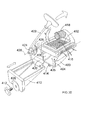
- the power cutter comprises a body 2 in which is mounted a two stroke internal combustion engine 24, a front handle 4, a rear handle 6, a support arm 7, a cutting blade 10, rotatably mounted on the support arm 7 and driven by the engine 24 via a rubber belt 26 and a blade guard 22.
- a starter 12 is provided to activate the engine 24.
- a plastic cover 19 covers the out side of the support arm 7 as shown in Figure 2 .
- the support arm 7 comprises two sections, a forward section 8 and a rearward section 20.
- the rearward section 20 is made from cast iron and is rigidly attached to the side of the gear housing 32 using bolts (not shown).
- the forward section 8 is made of cast iron and is slideably mounted on the rearward section 20.
- the forward section can slide in the direction of Arrow A. The method by which the forward section 8 is slideably mounted on the rearward section 20 is described in more detail below.
- the engine 24 has an output shaft 28 on which is mounted a drive wheel 30 for the rubber belt 26.
- the output shaft drives the drive wheel 30 via a centrifugal clutch (not shown) in well known manner.
- a driven wheel 32 is rotatably mounted on the end of the forward section 8 of the support arm.
- the driven wheel 32 is connected to the cutting blade 10 which is also mounted on the forward section 8 as described below.
- the belt 26 passes around the rearward section 20, between the two wheels 30, 32 to transmit the rotation of the engine to the cutting blade 10.
- the purpose of enabling the forward section 8 to slide in relation to the rearward section 20 is to enable the belt 26 to be tensioned as described below.
- a hub 16 covers the drive wheel 30.
- the rearward section 20 comprises two elongate slots 40 formed through the width of the rearward section 20.
- the elongate slots 40 are aligned with each other, are of equal length and run lengthways along rearward section 20 of the support arm.
- Formed through the forward section 8 are two corresponding holes 46.
- the part of the forward section 8 with the holes 46 is located alongside of the part of the rear section 20 with the elongate slots 40 so that the holes 46 align with a corresponding slot 40.
- a bolt 42 passes through each hole 46 and corresponding slot 40.
- a nut 44 is screwed onto the bolt 42 to sandwich the rearward and forward sections together and hold them in place using friction.
- the slots 40 enable the bolts 42, and hence the forward section 8, to slide relative to the rearward section 20.
- the nuts 44 are slackened so that the two can move relative to each other.
- the forward section 8 is then slid (using the belt tensioner described below) to the desired position, and then the nuts 44 are tightened to sandwich the rearward section 20 to the forward section 8 to prevent movement between the two.
- the forward and rearward interconnection mechanism is designed so that the forward section 8 can be located on either side of the rearward section 20 as shown in Figure 2 .
- the forward section 8 In normal operation, the forward section 8 is located on the same side of the rearward section 20 as the engine 24. This is indicated as position B. In this position, the cutting blade 10 is located closer to the central axis of the power cutter. However, it is sometimes desirable to have the cutting blade located towards the edge of the body 2 to enable it to cut near to a wall.
- the forward section 8 can then be moved to the other side of the rearward section 20 and be rotated through 180 degrees about the longitudinal axis 48 of the forward section 8 as indicated by Arrow D to the position C. In both orientations, the driven wheel 32 locates in the same position so that it can be driven by the belt 26.
- the belt tensioner comprises a metal plate 50 having two holes 46 through which the bolts 42 pass as seen in Figure 4 .
- the position of the plate 50 is fixed by the position of the bolts 42.
- Formed on the metal plate 50 are two hoops 52 which form apertures which are aligned.
- the shaft of an elongate bolt 54 passes through the hoops 52.
- the elongate bolt 54 can freely rotate and axially slide within the hoops 52.
- Threadedly mounted onto the bolt 54 is a nut 56.
- a spring 58 is sandwiched between the nut 56 and one of the hoops 52. The spring 58 prevents the nut from rotating.
- a stop 60 is integrally formed on the rearward section 20 of the supporting arm.
- the elongate bolt In order to tension the belt 26, the elongate bolt is rotated so that the nut moves towards the head 62 of the bolt 54. As its position is fixed by the spring 58, the nut remains stationary relative to the hoop 52 causing the bolt 54 to axially move within the hoops 52 so that the end 64 of the bolt 54 approaches the stop 60. Upon engagement of the stop 60, the end 64 and hence the bolt 54, can not move further and therefore the nut begins to move. The movement of the nut causes the spring 58 and hence the hoop 52 to move towards the head 62 of the elongate bolt 54. This in turn results in the plate 50, the two bolts 42 and the forward section 8 to move with the nut 56, the bolts 42 sliding within the two slots 40.
- the driven wheel 32 is rotatably mounted on the forward section 8.
- the driven wheel 32 is drivingly connected to the cutting blade 10 via a spindle 70 as will be described in more detail below.
- the blade guard 22 is pivotally mounted around the spindle 70 as will be described in more detail below.
- a grasp 72 is rigidly attached to the blade guard 22 which can held by an operator in order to pivot the blade guard 22.
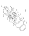
- Figures 12 to 18 show the mechanism by which the forward support 8 rotatably supports the cutting blade 10.
- the driven wheel 32 is rigidly attached to the spindle 70 via a flanged nut 74. Rotation of the driven wheel 32 results in rotation of the spindle 70.
- the spindle 70 is mounted in the forward section 8 using two ball bearing races 76, each comprising an inner track 78 rigidly connected to the spindle 70, an outer track 80 rigidly connected to the forward support 8, and a set of ball bearings 82 sandwiched between the two tracks 78, 80 which allow the outer track 80 to rotate relative to the inner track 78.
- a second support disk 86 comprises a central hole which is predominantly circular with the same diameter of the spindle 70, but with two flat sides which correspond in dimensions to the flat surfaces 84 of the spindle 70.
- the second support disk 86 is mounted on the end of the spindle 70 and abuts against shoulders 88 on the spindle 70 formed by the two flat surfaces 84.
- the flat surfaces 84 ensure that the second support disk is rotationally fixed to the spindle 70 so that rotation of the spindle 70 results in rotation of the second support disk 86.
- An adaptor 90 (described in more detail below) is mounted on the spindle 70.
- the adaptor can freely rotate about the spindle 70.
- the cutting blade 10 is mounted on the adaptor 90.
- a first support disk 92 comprises a central hole which is predominantly circular with the same diameter of the spindle 70, but with two flat sides which correspond in dimensions to the flat surfaces 84 of the spindle 70.
- the first support disk 92 is mounted on the end of the spindle 70 and abuts against the cutting blade 10.
- the flat surfaces 84 ensure that the first support disk 92 is rotationally fixed to the spindle 70 so that rotation of the spindle 70 results in rotation of the first support disk 86.
- a threaded hole 94 is formed in the end of the spindle 70 (see Figures 10 to 12 ).
- a second flanged nut 96 is screwed into the hole 94.
- the flange of the nut 96 pushes the first support disk 92 against the blade 10 which in turn pushes the blade 10 against the second support disk 86.
- the blade 10 becomes sandwiched between the two support disks 86, 92.
- Rotation of the support disks 86, 92 by the spindle 70 results in rotation of the blade due to the frictional contact of the blade 10 being sandwiched between the two disks 86, 92.
- By frictionally driving the blade 10 it allows rotational movement of the blade 10 relative to the spindle 70 if the blade becomes snagged during the operation of the power cutter.
- Cutting blades of different sizes can be used. Different sized cutting blades 10 have different sized holes in their centres through which the spindle 70 passes. It is intended that the present power cutter will be able to fit cutting blades 10 having two different sizes of hole through their centres. This is achieved by the use of the adaptor 90.
- the adaptor is mounted on the spindle 70 between the two support disks 86, 92. As well as being freely rotatable about the spindle 70, the adaptor 90 can axially slide along the spindle 70 between the disks 86,92.
- the adaptor comprises a front section 98 and a rear section 100.
- the front section 98 has a first outer diameter
- the rear section 100 has a second larger outer diameter.
- the two sections allow blades 10 with holes of different diameters to be mounted onto the spindle 70.
- a blade 10 with a central hole of a first diameter is mounted on the rear section 100 of the adaptor 90.
- a blade 10 with a central hole of a second diameter is mounted on the front section 98 of the adaptor 90.
- a spring 102 is sandwiched between the second support disk 86 and an inner shoulder 104 of the adaptor 90.
- the spring 102 biases the adaptor towards the first support disk 92.
- a circlip 106 is located around the spindle 70 which limits the maximum extent of axial travel of the adaptor 90. When the adaptor 90 is allowed to slide to its maximum extent and abut against the circlip 106, the rear section 100 is located centrally between the support disks 86, 92.
- the first support disk 92 When the first support disk 92 is mounted onto the spindle 70 after the blade, it pushes the blade 10 and adaptor 90 against the biasing force of the spring 102, moving the adaptor 90 towards the second support disk 86 as shown in Figure 13 .
- the blade When the blade is securely mounted on the spindle 70, it is centrally located between the support disks.
- the front section is similarly mounted centrally.
- the adaptor enables two types of blade 10 to be used, it moving automatically in accordance with blade size.
- the pivotal blade guard 22 will now be described.
- the blade guard 22 is held by being sandwiched between two pieces of rubber 108, 110.
- the blade guard 22 can pivot about the spindle 70. However, it is frictionally held by the two pieces of rubber 108, 110. In order to pivot the guard 22, the operator must overcome the friction between the guard 22 and the rubber 108, 110.
- a metal bracket 112 is attached to the forward section 8 via four bolts 114.
- the bolts pass freely through the forward section 8 and threadedly engage with threaded holes formed in the bracket 112.
- a helical spring 116 is sandwiched between the head 118 of each bolt 114 and the forward section 8, biasing the bolts 114 out of the holes, pulling the bracket 112 towards the forward section.
- Sandwiched between the bracket and the forward section 8 is a first piece of rubber, 108, the guard 22, a second piece of rubber 110 to form a rubber - guard - rubber sandwich.
- the strength of the spring 116 determines the amount of frictional force there is between the rubber 108, 110 and the guard.
- the two stroke internal combustion engine comprises a cylinder 120 in which is slideably mounted a piston 1000 which is connected to a rotatable crank 114.
- the reciprocating motion of the piston 100 in the cylinder 120 causes a rotational movement of the crank shaft 114 in well known manner. Movement of the piston is caused by the burning of aerated petrol/oil mixture in the cylinder, the ignition of which is caused by the ignition of a spark plug 730.
- the engine burns the fuel in well known manner to generate rotary motion of its crank shaft 114, which connects to the output shaft 28.
- the exhaust gases are then expelled from the engine 24 through an exhaust 146 to the surrounding atmosphere.
- the speed of the engine is determined by the amount of aerated petrol/oil mixture the carburettor 126 provides to the engine which in turn is is dependent on the amount the operator depresses the trigger switch 1070.
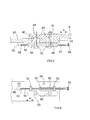
- the power cutter will comprise a petrol tank 124 in which is located petrol for driving the two stroke internal combustion engine 24. Petrol will pass from the tank 124 via passageway generally indicated by dashed lines 144 through the carburettor 126 which will mix it with air prior to being forwarded to the cylinder 120 where it will be burnt. Details of the supply of air, including its filtration will be described in more detail below.
- a second tank 128 will also be mounted in the body 2 as shown, in which lubricating oil will be contained. The oil will be pumped out of the tank 128 via a standard design of oil pump 130, which is mounted on the crank shaft housing which will be driven via a gear arrangement (not shown) from the crank shaft 114.
- the oil pump 130 will pump the oil through the oil passageways indicated by dashed lines 142 from the oil tank 128 via the pump 130 into the passageway 132 between the carburettor 126 and the cylinder 120, in a suitable form, for example, as a liquid or as a spray or atomized, and then mixing the oil with the air/petrol mixture generated by the carburettor 126. It will inject oil at the ratio 1:50 in relation to the petrol.
- a sensor unit 140 will comprise a sensor which will be mounted within the passageway 132 between the carburettor 126 and cylinder 120, or in the oil passageways 142 adjacent the passageway 132.
- the sensor will measure a parameter of the flow of the oil within the passageway and determine, using a signal processor incorporated into the sensor unit, whether oil is being pumped correctly in accordance with predetermined parameters in to the passageway 132 either by checking the pressure of the oil as it enters the passageway 132 or by detecting the presence of oil in the passageway 132.
- a parameter could be the rate at which the oil is pumped into the passageway 132.
- the sensor unit comprises a sensor consisting of two metal plates 1050; 1052 which are connected via wires 1056 to a signal generator/signal processor 1054.
- the metal plates are located within the passageway 132 between the carburettor 126 and cylinder 120, down stream of the oil passageways 142.
- the signal generator/signal processor 1054 sends a signal to the plates 1050; 1052 to determine the capacitance of the two plates.
- the capacitance is dependent on the material between the plates 1050; 1052 which will consist of aerated petrol and lubrication oil. As the amount of lubrication oil changes, the capacitance of the plates changes. This capacitance will be analyzed by the signal generator/ signal processor 1054 which, if the capacitance extends outside of a predetermined limit, will provide a signal to an electronic ignition system.
- the engine is controlled by the electronic ignition system.
- the sensor unit 140 will provide signals to the electronic ignition system about the amount of oil being pumped into the passageway 132. In the event that insufficient, excessive or no oil is pumped into the passageway due to the fact that the oil tank is empty or there is a blockage in an oil pipe 142 or there is a fault with the pump, the sensor unit 140 will send the signal to the ignition system. The ignition system will then either put the engine into an idle mode or switch the engine off entirely, depending on the settings of the ignition system. This will ensure that lubricating oil is always added to the petrol in the correct amount prior to combustion within the two stroke engine.
- the sensor unit 140 has been described as having the signal generator/ signal processor 1054 incorporated in the sensor unit 140, the signal generator/ signal processor 1054 could be incorporated into the electronic ignition system with the sensor unit only comprising the sensor.
- the two stroke internal combustion engine comprises a cylinder 120 in which is slideably mounted a piston 1000 which is connected to a rotatable crank 114.
- the reciprocating motion of the piston 100 in the cylinder 120 causes a rotational movement of the crank shaft 114 in well known manner. Movement of the piston is caused by the burning of aerated petrol/oil mixture in the cylinder, the ignition of which is caused by the ignition of a spark plug 730.
- the engine burns the mixture in well known manner to generate rotary motion of its crank shaft 114, which connects to an output shaft.
- the exhaust gases are then expelled from the engine through an exhaust 146 to the surrounding atmosphere.
- the engine is started using a pull cord in well know manner.
- the speed of the engine is determined by the amount of aerated petrol/oil mixture the carburettor 126 provides to the engine which in turn is is dependent on the amount the operator depresses the trigger switch 1070.
- the power cutter will comprise a petrol tank 124 in which is located petrol for driving the two stroke internal combustion engine 24. Petrol will pass from the tank 124 via passageway 144 through the carburettor 126 which will mix it with air from an air filter 890, prior to being forwarded to the cylinder 120 where it will be burnt.
- a second tank 128 will also be mounted in the body as shown in which lubricating oil will be contained. The oil will be pumped out of the tank 128 via an oil pump 700.
- the oil pump 700 will pump the oil through the oil passageways indicated by lines 142 from the oil tank 128 via the pump 130 into the passageway 132 between the carburettor 126 and the cylinder 120, in a suitable form, for example, as a spray or atomized, which is then mixed with the air/petrol mixture generated by the carburettor 126.
- a sensor 140 is mounted within the passageway 132 between the carburettor 126 and cylinder 120.
- the sensor monitors the amount of oil being added to the petrol/air mixture and sends a signal, via an electric cable 701, indicative of the amount of oil in the passageway 132 back to an electronic controller 716 (see Figure 34 ).
- the electronic controller comprises a signal processor which processes the signal and determines whether it is in accordance with predetermine parameter or not. If the electronic controller determines that the oil is not being supplied in sufficient amounts, it place the engine an idle mode or stop it altogether.
- Such a sensor can be of a capacitance type whereby the sensor monitors the change in capacitance between two plates, the capacitance being a function of the amount of oil there is in the petrol/air mixture.
- Such a sensor has been described previously with reference to Figure 32 .
- the carburettor 126 will now be described with reference to Figure 47 .
- the design of the carburettor is similar to that previously described with reference to Figure 31 . Where the same features are present the same reference numbers have been used.
- the main difference between that disclosed in Figure 31 and that in Figure 47 is that the first pivotal plate 1046 which acts as the choke for the carburettor has been removed. Instead, a third passageway 1100 has been added.
- the third passageway 1100 connects to the second chamber 1014 via a solenoid valve 1102.
- the other end of the third passageway 1100 connects with the air passageway 1004 down stream of the narrow section 1008.
- the solenoid valve 1102 comprises a solenoid 714 and a pin 1106.
- the pin can axially slide (Arrow M) between a first position where the tip of the pin 1106 engages with a restriction 1108 in the third passageway 1100 to block the third passageway 1100 and a second position where the tip is located away from the restriction 1108 to open the third passageway 1100.
- the pin 1106 is biased to its first position.
- Activation of the solenoid by the provision of an electric current, causes the pin 1106 to move against the biasing force from its first position to its second position opening the third passageway 1100.
- Deactivation of the solenoid 714 by the removal of an electric current causes the pin 1106 to move under the influence of the biasing force from its second position to its first position, closing the third passageway 1100.
- the carburettor functions in the same manner as that described with reference to Figure 31 .
- No current is supplied to the solenoid 714, and the pin 1106 engages with the restriction 1108 and blocks the third passage 1100.
- a current can be supplied to the solenoid 714, which causes the pin 1106 to slide away from the restriction, unblocking the third passageway 1100 and allowing petrol to pass through the third passageway 1100 and enter the air passageway 1004.
- This increases the amount of petrol relative to the amount of air in the aerated petrol exiting the air passageway 1004 to enable the engine to run smoothly whilst it is cold.
- the solenoid 714 can be switched off by removing the electric current to it, allowing the pin 1106 to slide towards the restriction 1108 to block the third passageway and prevent any further petrol from passing through it.
- a fourth passageway 1110 which connects between the hollow chamber 1034 and the air passageway.
- This passageway provides an air passage between the two. When there are increases or decreases in the air pressure in the air passageway 1004, these are transmitted to the hollow chamber 1034. These in turn are transmitted to the second chamber 1014 via the diaphragm 1032 which influences the flow of petrol into the second chamber and into the air passageway 1004.
- the fourth passageway 1110 acts as a feed back mechanism to improve performance of the carburettor.
- the solenoid is used when the engine is cold to provide an air/petrol mixture which is richer in petrol to help start the engine. When the engine is warm, the solenoid is switched off. The temperature of the engine is measure using a sensor 710 located on the engine block.
- the solenoid 714 is used to replace the choke on exiting designs of carburettor whereby which an operator would manually adjust the valve to start the engine when it is cold.
- the electronic controller 716 operates the solenoid dependent on the temperature of the engine.
- the main difference between that disclosed in Figure 31 and that in Figure 47 is that the first pivotal plate 1046 which acts as the choke for the carburettor has been removed and has been replaced by a heating element 1200.
- the heating element 1200 When the engine is cold, the heating element 1200 is switched on and heats the air flow as it passes through the carburettor. This provides heated aerated petrol which enables the engine to run smoothly until it has achieved an acceptable running temperature.
- the heating element 1200 would be controlled by the electronic controller 716. This could be used to replace that described previously
- the engine ignition system is controlled by an electronic controller 716, the function of which is described in more detail below with reference to Figure 34 .
- a fly wheel 702 which contains a number of metal fins 704 which form an impeller. As the fly wheel 702 rotates, the impeller blows air around the out side of the engine. Adjacent the impeller 702 are two generators 706; 708. The two generators generate electricity using magnets and the change of inductance caused by the rotating flywheel 702. As the fly wheel 702 rotates, it causes the two generators 706; 708 to produce electricity.
- the first generator 706 is used to provide electricity for the ignition system of the engine and the electronic controller 716.
- the second generator 708 is used to provide electricity for the oil pump 700 and the solenoid 714 in the carburettor. Both are connected to the electronic controller 716 via cables 717.
- the first sensor 710 monitors the temperature of the engine block and sends a signal via an electric cable 711 indicative of the temperature to the electronic controller 716.
- the second sensor 712 monitors the angular position of the flywheel 702 and sends a signal via an electric cable 713 indicative of the angular position of the flywheel 702 back to the electronic controller 716. This signal can also be used by the electronic controller 716 to determine the rate of rotation of the fly wheel 702, as well as its angular position.
- the oil pump 700 is an electrically powered oil pump 700, the power for which is supplied by the electronic controller 716 via electric cable 715.
- the oil pump is shown in Figure 35 .
- the oil pump comprises a piston 850 which can axially slide within a housing 1202 over a limit range of axial movement which is determine by a stop mechanism 1204.
- a spring 854 biases it to a predetermined position.
- a chamber 852 is located below the piston 850.
- a solenoid 1206 surrounds the piston and moves it axially when an electric current is applied.
- the piston 850 is biased in direction of Arrow R by a spring 854. Activation of the solenoid moves the piston against the biasing force of the spring 854 in the opposite direction to Arrow R.
- a passageway 1208 is formed through the piston 850. Oil is fed into the passageway via an inlet 1210.
- a first valve comprising a ball bearing 1212 and spring 1214 is located between the end of the passageway 1208 and the chamber 852.
- a second valve comprising a ball bearing 1216 and a spring 1218 is located between the base the chamber 852.
- the oil pump 700 is driven by the electronic controller 716 which sends a square shaped voltage signal 892 to the oil pump (see Figure 45A )
- the voltage When the voltage is at V1, it causes the piston 850 of the pump to move, reducing the size of the oil chamber 852. This causes a preset amount of oil to be pump out of the chamber 852.
- voltage When voltage is "0", the piston returns to its starting position due to the spring 854, enlargening the chamber 852 and allowing the chamber 852 to fill with oil.
- the oil pump is capable of running at two speeds (the first speed shown in Figure 45A , the second speed being shown in Figure 45B where the frequency of the square shaped voltage signal 892, and hence the movement of the piston 850, is double) and its general operation is described in more detail below.
- the spark plug 730 is connected to the electronic controller 716 via a cable 732. Ignition of the spark plug is controlled by the electronic controller 716.
- a primer 734 is mounted on the rear wall 736 of the housing 800 of the power cutter.
- the primer is a manual pump.
- a pipe 738 connects from the petrol tank 124 to the primer 734.
- a second pipe 740 connects from the primer to the carburettor 126.
- the primer consists of two valves 742; 744 located in series which allow the petrol to flow one way through them only (indicated by Arrows A and B).
- Located between the two valves 742; 744 is a chamber 750 having a rubber dome 746 forming a wall which is accessible to the user of the power cutter.
- One valve 742 only allowing petrol to enter the chamber 750, the other only allowing petrol to leave the chamber 750.
- the operator compresses the rubber dome 746 (shown as dashed lines 748). This reduces the amount of volume in the chamber 750 formed between the valves and hence the amount of space which can contain petrol.
- petrol is ejected from the primer through the one of the valves 744, as the second valve 742 remains closed, preventing petrol from leaving the chamber 750 via that valve 742.
- the volume of the chamber 750 increases, causing petrol to be sucked into the chamber 750 through the second valve 742 as the first valve remains closed 744 preventing petrol from entering the chamber 750 through that valve 744.
- Repetitive compressing and releasing of the dome 746 results in the petrol being pumped through the primer 734.
- the primer is arranged so that the operator can manually pump the petrol from the tank 124 to the carburettor 126 through the pipes 738; 740.
- the purpose of the primer is to enable the operator to place petrol into the carburettor. Otherwise the operator has to spin the engine a number of times using the pull cord before a sufficient amount of petrol is sucked through into the carburettor 126.
- a DECO valve 752 is mounted on the side of the cylinder 120.
- the valve 752 is opened manually by the operator prior to starting the engine.
- the DECO valve reduces the pressure within the cylinder 120 prior to ignition. This enables the starting of the engine using the pull cord to be made easier as the amount compression of the petrol/air mixture required is reduced.
- the DECO valve automatically closes.
- the electronic controller 716 has an on/off switch 754 in the form of a rotatable knob 758.
- the switch is connected to the electronic controller via an electric cable 756.
- the knob 758 as a pointer 764 integrally formed on its periphery.
- the rotatable knob 758 has two angular positions between which it can rotate. In the first position, the switch is ON. In this position, the pointer 764 points to an ON label 762 (see Figure 1 ). In the second position, the switch is OFF. In this position, the pointer 764 points to an OFF label 760.
- the rotatable knob is in the ON position, the operator can start the engine and use the power cutter.
- the rotatable knob 758 is in the OFF position, the engine is prevented from being started. If the rotatable knob 758 is moved from the ON to the OFF position when the engine is running, the engine is automatically switched off.
- a safety button 766 is located in the centre of the knob 758. If the engine is running (ie the knob is in the ON position), depression of the safety button 766 will result in the engine being switched off. The knob 758 then automatically returns to the OFF position. If the knob 758 is prevented from returning to the OFF position after the safety button has been depressed, the engine will not be able to be started until the knob 758 has been allowed to return to the OFF position.
- the ON/OFF switch assembly consists of the rotatable knob 758, a crank 768, a switch cam 770 and the safety button 766.
- the crank 768 is rigidly fixed into the rear wall 736 of the housing 800 and prevented from rotation.
- the crank 768 comprises a socket 772 into which is rigidly mounted a micro switch 774 (see Fig 49C).
- Rotatably mounted on the outside of the crank 768 is the knob 758.
- Rotatably mounted on the inside of the crank 768 is the switch cam 770.
- a bolt 778 which passes through the base of a tubular recess 776 formed in the knob 758, screws into the switch cam 770 and is rigidly attached to it.
- Sandwiched between the head of the bolt 778 and the base of the recess 776 is a spring 780.
- the bolt 778 and spring 780 hold the knob 758 and switch cam 770 onto the crank 768, biasing them towards each other as the spring biases the head of the bolt 778 away from the base of the recess 776.
- the knob can rotate through a limited range of movement (between the ON and OFF positions) relative to the crank 768.
- the range of positions is limited by pegs 786 formed on the underside of the knob engaging with recesses 788 formed in the edge of the rear wall 736 of the housing.
- the switch cam 770 can also rotate through a limited range of movement relative to the crank 768.
- the switch cam 770 can axially slide relative to the crank 768 in a direction parallel to the longitudinal axis of the bolt 778 over a limited range of movement, the range being limited by the length of the bolt 778 within the recess 776.
- the bolt 778 rotates and slides with the switch cam 770.
- the safety button 766 is mounted within the tubular recess 776 formed in the knob 758 and encloses the end of the bolt 778 located in the recess776 and the spring 780 (see Fig 40 ).
- the safety button 766 can axially slide within the recess 776 towards or away from the switch cam 770.
- the range of outward axial movement of the safety button is limited by stops 782 each engaging with an inner step of the knob 758.
- the head of the bolt 778 directly abuts the underside of the safety button 766. Depression of the safety button, causes the bolt 778 to be pushed through the base, compressing the spring 780, moving the switch cam 770 away from the crank768 and knob 758.
- a long helical spring 784 Connected between the knob 758 and the crank 768 is a long helical spring 784.
- the helical spring 784 locates in a circular channel 790 formed on the underside of the knob 758 as best seen in Figure 41 .
- One end abuts against a wall 792 at the end of the channel 790.
- the other end abuts against a stop (not shown) formed on the crank 772.
- the spring 784 rotationally biases the knob 758 relative to the crank to its OFF position.
- a leaf spring 794 Connected between the switch cam 770 and the crank 768 is a leaf spring 794 as best seen in Figures 43 and 44 .
- One end of the leaf spring 794 is connected using a small bolt 796 to the switch cam 770. The other end abuts a stop 798 on the crank 768.
- the leaf spring 794 rotationally biases the switch cam 770 relative to the crank to an OFF position.
- each of the two ramps 820 is located in a corresponding ramp recess 824 with the ramp ends 822 of each ramp 820 abutting directly against the ramp recess ends 826 of the corresponding ramp recess 824.
- crank ramps 828 Formed on the underside of the crank 768 are two crank ramps 828, each ramp 828 having a crank ramp end 830 as best seen in Figure 39C .
- switch cam crank ramps 832 Formed on the side of the switch cam 770 which faces the knob 758 are switch cam crank ramps 832 which have switch cam crank ramp ends 834 as best seen in Figure 40 .
- the micro switch 774 comprises a pin 838 which projects from the body of the micro switch 774.
- the pin 838 is capable of sliding axially in or out of the body of the micro switch 774 and biased to its outer most position by a spring (not shown) inside the micro switch 774.
- the pin 838 engages the peripheral cam 836. Rotation of the switch cam 770 causes the pin 838 to slide along the peripheral cam 836, which causes it to be pushed into the body of the micro switch 774 against the biasing force of the spring, or allows it to slide out of the body of the micro switch 774 under influence of the spring.
- the knob 758 and the switch cam 770 are both located in their OFF positions.
- the operator of the power cutter desires to turn the unit on using the ON/OFF switch.
- the operator uses their hand to rotate the knob 758 from its OFF position to its ON position.
- the knob 758 When the knob 758 is rotated, it causes the cam switch 770 to rotate in unison as the rotary movement is transferred from the knob 758 to switch cam 770 by the ramp ends 822 of each ramp 820 pushing the ramp recess ends 826 of each corresponding ramp recess 824, against which it abuts, in the direction of Arrow M in Figure 40 , to cause the switch cam 770 to rotate with the knob 758.
- the switch cam 770 When the switch cam has rotated sufficiently that the crank ramp ends 830 and the switch cam crank ramp ends 834 become aligned, the switch cam 770 axially slides under the biasing force of the spring 780 towards the knob 758, ensuring that the crank ramp end 830 and the switch cam crank ramp ends 834 abut against each other as shown in Figure 39E .
- the switch cam 770 When the crank ramp ends 830 and the switch cam crank ramp ends 834 abut each other as shown in Figure 39E , the switch cam 770 is in its ON position and is prevented from returning to its OFF position, under the influence of the leaf spring 794, as the crank ramp ends 830 and the switch cam crank ramp ends 834 prevent relative movement as they are jammed against each other.
- the knob 758 is prevented from returning to its OFF position under the influence of the spring 784 by the ramps 820 being held within the ramp recesses 824 by the action of the spring 780 which overrides the spring 784.
- the switch cam 770 rotates from the OFF position (see Figure 39A ) to the ON position ( Figure 39B )
- the peripheral cam 836 rotates, which in turn allows the pin 838 to extend from the body of the micro switch 774. This in turn makes a connection which allows the electric controller 716 to activate the power cutter and allow it to start when the pull cord is pulled.
- the assembly of the ON/OFF switch is now ON with the knob 758 and the switch cam 770 both in their ON positions, allowing the pin 838 to extend from the body of the micro switch 774. There are two way of switching the ON/OFF switch assembly to its OFF position.
- the first method comprises the depression of the safety button 766. Depression of the safety button 766 causes the head of the bolt 778 to slide towards the base of the recess 776 of the knob 758, compressing the spring 780, which in turn causes the switch cam 770 to axially slide away from the knob 758. As the switch cam 770 axially slides, the switch cam 770 moves away from the crank 768, which in turn causes the crank ramps 828 and the switch cam crank ramps 832 to move away from each other, and thus causes the crank ramp ends 830 and the switch cam crank ramp ends 834 to disengage. As such, the switch cam 770 can now rotate back to its OFF position under the influence of the leaf spring 794.
- the knob 858 will also return to its OFF position as the ramp recesses 824 rotate with the switch cam 770. Should the ramps 820 become disengaged from the ramp recesses 824 due to the sliding movement of the switch cam 770 relative to the knob 758, the knob 758 will return to its OFF position under the influence of the spring 784 between the knob 758 and the crank 768.
- the second method of switching the ON/OFF switch assembly OFF comprises the rotation of the knob 758.
- the operator rotates the knob 758 to its OFF position.
- rotation of the knob 758 urges rotation of the switch cam 770.
- the switch cam 770 is prevented from rotating as the crank ramp ends 830 and the switch cam crank ramp ends 834 abut each other. Therefore, the ramps 820 slide out of the ramp recesses 824, the ramp ends 822 moving away from ramp recess ends 826.
- the switch cam 770 As the ramps 820 slide out of the ramp recesses 824, the switch cam 770, which is prevented from rotating, axially slides away from the knob 858 by the caming action of the ramps 820 and ramp recesses 824.
- the switch cam 770 When the switch cam 770 has slid sufficiently far enough away from the knob 758, the crank ramp ends 830 and the switch cam crank ramp ends 834, which are sliding away from each other, become disengaged.
- the switch cam 770 can rotate under the influence of the leaf spring 794 to its OFF position.
- the knob 758 will move under the influence of the operator and/or the spring 784. As such, both the knob 758 and the switch cam 770 return to their OFF position where they are held by the springs 784; 794.
- the operator first activates the DECO valve 752 and then pumps some petrol into the carburettor 126 using the primer 734. The operator then switches the ON/OFF switch to ON by rotation of the knob 758 to its ON position. The operator then pulls the pull cord to rotate the crank 114 of the engine. As the crank 114 rotates, the fly wheel 702 also rotates causing the two generators 706; 708 to produce sufficient electricity to operate the power cutter.
- the electronic controller checks the temperature of the engine using sensor 710. If the engine is cold, it uses the electricity from the second generator 708 to power the solenoid 714 in the carburettor to set the "automatic choke". The second generator 708 is not powerful enough to power both the oil pump 700 and solenoid 714 at the same time. Therefore, when the electronic controller 716 is operating the solenoid 714, it switches off the oil pump 700. It has been found that the period during which lubricating oil is not required before the engine is damaged is greater than that required to heat up the engine.
- the electronic controller supplies the power to the spark plug to cause combustion in the engine, the power being provided by the first generator 706, the timing being determine by the electronic controller 716 based on the signal provided by the sensor 712 in relation to the angular position of the fly wheel 702.
- the DECO valve automatically closes.
- the electronic controller 716 continues to monitor the engine temperature and when it has reached a predetermine temperature, the electronic controller 716 switches the solenoid 714 in the carburettor 126 off.
- the electronic controller 716 then commences supplying a square shape voltage signal to the oil pump to commence pumping oil.
- the electronic controller monitors the speed of the engine using the signal provided by the sensor 712 monitoring the angular position of the fly wheel 702 to calculate the rotational speed. If the rotational speed is below a predetermined value, the electronic controller 716 sends a signal (Figure 35A) to the oil pump 700 to cause it to pump at a slow speed.
- the electronic controller 716 sends a signal ( Figure 35B) to the oil pump 700 to cause it to pump at a higher speed.
- the speed of the engine is dependent on the operator squeezing a trigger switch which connects to the carburettor via a cable.
- the electronic controller 716 Whilst the engine is running the electronic controller 716 monitors the oil being added to the petrol/air mixture using the sensor 140. If the sensor 140 sends a signal that indicates that the rate of flow of the oil being pumped by the oil pump 700 has dropped below a predetermine amount (eg there is a blockage in the oil pipe142 or the tank 128 is empty), the electronic controller places the engine into an idle mode using the ignition system so that the engine runs, but at a minimal rate.
- a predetermine amount eg there is a blockage in the oil pipe142 or the tank 128 is empty
- the engine controller can place the engine in idle mode by altering the timing of the ignition of the spark plug relative to the angular position of the crank shaft or the number of ignitions of the spark plug relative to the number of rotations of the crank shaft.
- the engine controller can ignite the spark ever two or three rotations of the crank shaft, for example, providing only a half or a third of the power than if the spark plug was ignited every rotation, as would be the case during the normal operation of the engine.
- the operator can not speed up the engine using the trigger switch 1070 until the sensor 140 detects the flow of oil. This protects the engine from damage due to a lack of lubrication. It has been found that the engine can run in idle mode for a considerable period of time before damage to the engine results.
- the operator In order for the operator to stop the power cutter, the operator either depresses the safety button 766 or rotates the knob 758 to its OFF position.
- Figure 46A shows the voltage supplied to the oil pump 700
- Figure 46B shows the current supplied to the oil pump 700 when the oil pump is pumping but there is no oil being pumped
- Figure 46C shows the he current supplied to the oil pump when the oil pump is pumping oil.
- the oil pump 700 running at the slow speed.
- a square wave voltage V1 indicated by line 900 is supplied to the oil pump as shown in Figure 46A .
- the current indicated by line 902 starts to rise from zero at t0, when the voltage applied rises to V1 and increases towards I1.
- the amount of current drops 904 before increasing 906 again to I1.
- the current drops after t2 seconds before beginning to rise again at t3 seconds.
- the drop in current occurs when the piston 850 in the oil pump 700 reaches its maximum amount of travel due to the solenoid 1206 and then bounces back slightly due to the piston's 850 impact at its maximum distance of travel.
- the speed of travel of the piston 850 in the oil pump increases as there is less resistance. As such it reaches its maximum amount of travel sooner. Therefore, as shown in Figure 46B , it reaches a lower value of current I2 before the value of current drops 908 and then rises 910 again towards I1. Furthermore, it only takes less time before the current drops 908 and rises 910 again than if the oil pump 700 was pumping oil.
- the signal processor in the electronic controller 716 can monitor when the current begins to drop versus the start of the voltage pulse and the value of the current at this point to determine whether the pump is pumping oil or not. If t is not, the electronic controller can place the engine in idle mode.
- the petrol tank 124 will be mounted within the body of the unit as generally indicated in Figure 19 .
- the tank 124 will be sealed by a fuel cap 13 as shown on Figure 2 .
- the fuel cap will comprise an inner cap 202, a clutch 204 and an outer cap 206.
- the inner cap is of a tubular construction with one end 210 being sealed.
- the thread 208 slidingly engages with a thread formed around the external surface of the neck of the fuel tank 124.
- a seal 214 Located inside the inner cap 202 adjacent the end 210 is a seal 214. When the fuel cap is screwed onto the fuel tank, the seal 214 ensures that no petrol can escape from the tank.
- the inner cap 2 locates within the outer cap 206. Sandwiched between the two is the clutch 204.
- a clip 216 locates within a groove 218 of the inner cap and also engages with an inner groove 220 formed within the outer cap. The clip holds the inner cap inside the outer cap whilst allowing it to freely rotate within the outer cap 206.
- the inner cap comprises a number of teeth 222 integrally formed with the inner cap. The teeth locate within corresponding slots 224 formed within the clutch, thus rotation of the inner cap causes rotation of the clutch 204.
- the pegs 228 face towards the internal end wall 230 of the outer cap.
- Formed on the wall are a plurality of ridges 232.
- the pegs on the clutch are arranged to co-operate with the ridges 232 in the outer cap.
- Rotation of the outer cap 206 causes the ridges 232 to engage with the pegs 228 resulting in rotation of the clutch 204, which in turn rotates the inner cap 202 via the teeth 222.
- the inner cap 202 threadingly engages with the neck of the fuel tank, the rotation of the inner cap 202 being caused by rotation of the outer cap 6 via an operator rotating it using a finger grip 234.
- the seal 214 located within the inner cap engages with the end of the neck of the fuel tank, the inner cap 202 is prevented from further rotation. This in turn prevents further rotation of the clutch 204.
- the ridges 232 are caused to ride over the pegs 228, the movement of the pegs 228 being allowed by the resilient arms 226 upon which they are mounted. In this way the operator can rotate the outer cap whilst the inner cap remains stationary thus preventing the operator from over-tightening the fuel cap onto the neck of the fuel tank.
- the two stroke engine comprises a carburettor 126 which mixes liquid fuel with air to generate a combustible mixture for powering the engine.
- a carburettor 126 which mixes liquid fuel with air to generate a combustible mixture for powering the engine.
- a large amount of dust is generated which mixes with the surrounding air. This results in dust laden air.
- a filter unit 316 comprising a plastic base 318 and filter paper 320 folded to form pleats.
- the filter unit 316 is located within the body 2 so that the pleats 320 hang vertically downwards when the power cutter is in a storage position as shown in Figures 1 and 2 .
- Air will be sucked through the filter system by the carburettor 126. Air enters slots 314 on the rear of the body 2. Air passes (Arrow G) to a space 322 underneath the filter unit 316 and then passes through the filter paper 320 to a space 324 above the filter unit 316. Any dust entrained within the air is trapped by the filter unit 316 and held within the pleats of the filter paper 320.
- the clean air then passes from the space 324, through a hose 326 to the carburettor 126 located below the space 322 below the filter unit 316.
- a cleaning device In order to enable the operator to remove the dust trapped within the pleats of the filter paper 320, a cleaning device is provided.
- the cleaning device comprises a rubber flap 328, mounted on the top of a plastic base 330, a brush 332 attached to the bottom of the plastic base 330, a handle 334 attached to the plastic base 330 via to rigid arms 338.
- the base 330 can slide within the space 322 below the filter unit 316, widthways across the body 2. Movement is caused by the operator pulling the handle 334 away from the side of the body 2.
- Two springs 336 bias the handle 334 towards the side of the body 2.
- the operator pulls the handle 334, to move the base 330 across the width of the body 2 in the direction of Arrow H, and then releases it to allow it to return in the opposite direction under the biasing force of the springs 336.
- the rubber flap 328 engage with the pleats 320, as best seen in Figure 25 , knocking the dust of the pleats 320.
- the dust drops to the base 340 of the space 322 below the filter unit 316.
- the brush 332 slidingly engages with the base 340 of the space 322.
- the brush 332 brushes the dust to one side or the other, depending on the direction of movement.
- An aperture 344 is formed on one side of the body 2. As the brush approaches the side of the body, it pushes the dust being swept along the base through the apertures, expelling it from the body 2.
- Figure 4 shows the flap 28 moving perpendicularly to the direction of the pleats 320
- the filter paper 320 may be replaced by a plurality of brushes 342.
- the body of the power cutter is constructed in the form of a plastic casing constructed from a number of plastic clamshell rigidly connected together.
- the rear clam shell 430 connects to the rear handle 6.
- the rear handle 6 is integral with the rear clam shell 430.
- the whole clam shell 430 needs to be replaced. As handle breakage is common it is desirable to avoid this.
- the rear handle 6 in the present invention is constructed as a separate item to that of the rear clam shell 430 (or body 2).
- the rear handle 6 is constructed from a separate single clam shell 431 which is joined at its top 432 at two points 434 and at its bottom at a single point 436. Each of the three points 434, 436 is joined using a bolt which screws into the plastic clam shell 430. Vibration dampening material may be used in conjunction with the bolts to reduce the amount of vibration transferred to the handle 6 from the body 2. The use of such vibration dampening material allows limited movement of the handle 6 relative to the rear clam 430 at each of the three points. The movement could be either linear or rotational.
- One such construction is to surround the bolts with the dampening material in order to sandwich it between the bolts and parts of the clam shell of the rear handle 6.
- the top 432 of the handle 6 is in the form of a cross bar.
- the shape is such that the bolts fastening the top 432 of the handle to the rear of the clam shell 430 are aligned with each other and thus provide a pivot axis 440 for the rear handle 6 about which it can rotate by a limited amount.
- the handle may be constructed from a number of clam shell connect rigidly together. Rubber soft grip over mold 442 may also be added to the handle for additional comfort.
- the filter device comprises a box 400 in which is mounted filter paper 402 which is pleated and which hangs down from the top section from inside the box.
- a space 404 is formed below the pleat.
- a large aperture 406 is formed in the side of the box below the filter paper and through which a drawer 408 can be slid.
- the drawer comprises a receptacle 410 which locates in the space 404 immediately below the filter paper 402.
- the drawer 408 can be fastened into place via a screw 412 which threadedly engages a threaded hole 414 in the box.
- Air passes through slots 314 into the box and into the receptacle 410 in the space 404 below the filter paper 402 then through the filter paper 402 into a space 416 above the filter paper 402 and then exits the space 416 above the filter paper through a flexible tube 418 to the carburettor 126. Any dust contained in the air entering the box 400 is blocked by the filter paper 402.
- a combination of two systems have been proposed to shake any dust within the filter paper 402 off the filter paper 402 into the drawer 408 so that the drawer 408 an be removed for emptying.
- the first system is very similar to that disclosed in the first embodiment described above and comprises a rubber flap 420 which is attached to the front end of the drawer 408.
- the rubber flap 420 engages with the pleated filter paper 402.
- the rubber flap 420 successively hits the base of each pleat causing any dust on the pleats to be knocked off and into the drawer 408.
- the action of inserting or removing the drawer 408 into the box 400 causes dust on the filter paper 402 to be loosened and allowed to be removed.
- the second system relies on the starter cord 422 of the start 12 for the two stroke engine 24 of the power saw.
- the power cord 422 needs to be pulled in order to cause it to rotate.
- the cord 422 rotates a pulley wheel 424 which causes an eccentric pin 426 to rotate about the axis 428 of the pulley 420.
- This causes one side of the box 400 to oscillate up and down as indicated by arrows Y.
- the other side of the box 400 is pivotally attached about an axis 435 to the body of the power cutter.
- the reciprocating motion of the box 400 causes dust in the filter 402 to be shaken off the filter paper 402 and into the drawer 408.
- Each system cause dust trapped in the filter paper 402 to fall into the drawer.
- the action of pulling the starter cord cleans the filter paper 402. Then, the operator can subsequently clean the filter paper during the operation of the power cutter by inserting and removing the drawing 408.
Landscapes
- Engineering & Computer Science (AREA)
- Mechanical Engineering (AREA)
- General Engineering & Computer Science (AREA)
- Chemical & Material Sciences (AREA)
- Combustion & Propulsion (AREA)
- Life Sciences & Earth Sciences (AREA)
- Forests & Forestry (AREA)
- Transportation (AREA)
- Wood Science & Technology (AREA)
- Sustainable Development (AREA)
- Sustainable Energy (AREA)
- Chemical Kinetics & Catalysis (AREA)
- Sawing (AREA)
- Processing Of Stones Or Stones Resemblance Materials (AREA)
- Lubrication Details And Ventilation Of Internal Combustion Engines (AREA)
- Lubrication Of Internal Combustion Engines (AREA)
- Electrical Control Of Air Or Fuel Supplied To Internal-Combustion Engine (AREA)
- Combined Controls Of Internal Combustion Engines (AREA)
- Means For Warming Up And Starting Carburetors (AREA)
- Control Of The Air-Fuel Ratio Of Carburetors (AREA)
- Control Of Vehicle Engines Or Engines For Specific Uses (AREA)
- Harvester Elements (AREA)
Abstract
Description
- The present invention relates to a power cutter.
- A typical power cutter comprises a housing in which is mounted a two stroke internal combustion engine. Attached to the side of the housing is a support arm which extends forward of the housing. Rotatably mounted on the end of the support arm is a cutting blade, usually in the form of a grinding disk. The motor is drivingly connected to the cutting blade via a drive belt. The rotary output of the engine rotatingly drives the cutting blade via the drive belt. The drive belt is driven via a centrifugal clutch which enables the out drive spindle of the engine to disengage from the belt when the engine is running at a slow speed, to allow the engine to continue running, whilst disengaging any drive to the cutting blade to allow the blade to be stationary.
- Also mounted in the housing is a petrol tank which provides petrol for the engine via a carburettor. An oil tank can also be provided, which provides lubricating oil to mix with the petrol, to lubricate the engine.
- Mounted on the rear of the housing is a rear handle for supporting the power cutter, which contains a trigger switch for accelerating the engine upon depressing. Depression of the trigger switch causes more of the aerated petrol/oil mixture to be injected into the engine which in turn causes the speed of the engine to accelerate.
-
GB2232913 W02005/056225 show examples of such power cutters. - A known problem with all two stokes engines is the lubrication of the crank shaft 114 (using the reference numbers shown in
Figure 19 ) andpiston 1000. This is due to the fact that the petrol/air mixture first passes through a chamber 18 in thecylinder 120 below thepiston 1000 before being forced into thechamber 122 above thepiston 16 before being ignited. This prevents the use of lubricating oil being pumped around thecrank shaft 114 on the underside of thepiston 1000. Therefore, in existing designs of two stoke engines, a mixture of aerated petrol and lubricating oil is burnt within the engine, the oil providing lubrication for thecrank shaft 114 andpiston 1000 prior to being burnt with the petrol during the combustion cycle. A common problem with the use of two stoke engines is that the operator forgets to add the oil to the petrol or adds it in an inconsistent manner, thus resulting in damage to the engine. This particularly so for power cutters as often power cutters are often hired out to operators. As such, operators are not familiar with using them; they are not in the operators possession for long; the operator does not know who had it previously or how the previous operator used the power cutter; and, as the operator does not own it, has less reason to care for the long term maintenance of the power cutter. Therefore, it is desirable that a mechanism is provided to prevent or limit damage to the two stroke engine of the power cutter to ensure that sufficient lubrication oil is included in the aerated petrol which prior to entering the engine. - It is possible to add lubricating oil directly to the petrol in the petrol tank. However, this relies on the operator ensuring that the correct ratio of lubricating oil to petrol is achieved. This can be difficult as it may be hard to determine how much petrol is already in the petrol tank and how much lubricating oil has already been added. Therefore, it is preferable to have a separate oil tank which is filled with lubricating oil and which is then pumped from the tank and mixed with the petrol. This enables the amount of oil be added to the petrol to be controlled more accurately.
- The two stroke engines of power cutters use a carburettor to provide aerated petrol for powering the engine. A typical design of such a carburettor is shown in
Figure 31 . Referring theFigure 31 , the carburettor comprises ahousing 1002 through which is formed anair passageway 1004 through which air can pass in the direction of Arrow Q. Theair passageway 1004 at its entrance and exit has the same cross sectional area. However, formed part way along the length of theair passageway 1004, is arestriction 1006 which reduces the size of the cross sectional area of the air passageway and which acts as a venturi; theair passageway 1004 narrowing and then expanding as the air passes through it. This causes the rate of flow of air through thenarrow section 1008 of theair passageway 1004 to increase. - Petrol enters the carburettor via an
inlet 1010 and fills afirst chamber 1012. Thefirst chamber 1012 is connected to asecond chamber 1014 via apetrol passageway 1016. Petrol fills thesecond chamber 1014 via thepetrol passageway 1016. - An
adjustable needle valve 1020, which has a pointed tip and an elongate body, is mounted in thepetrol passageway 1016 and which can axially slide within thepassage way 1016. Thepetrol passageway 1016 comprises anarrow section 1018 The tip of theadjustable needle valve 1020 projects towards thenarrow section 1018 and can block thenarrow section 1018 when theadjustable needle valve 1020 is moved towards it or open thenarrow section 1018 when it is moved away from it. - The rear end, remote from the tip, of the
adjustable needle valve 1020 projects into thesecond chamber 1014. Attached to the rear end of theadjustable needle valve 1020 is afirst lever 1022 which connects to asecond lever 1024 via apivot point 1026. One of the walls of thesecond chamber 1014 is aflexible diaphragm 1032 which can move to adjust the volume of thesecond chamber 1014. Ahollow chamber 1034 is formed on the other side of thediaphragm 1032. The end of thesecond lever 1024 connects to thediaphragm 1032. Thesecond lever 1024 also connects to asolid wall 1028 of thesecond chamber 1014 via aspring 1030. Thespring 1030 biases the second lever to a predetermine position, which in turn biases thefirst lever 1022 to a predetermined angular position. Flexing of thediaphragm 1032 causes pivotal movement of the first and second levers against the biasing force of thespring 1030. Movement of thefirst lever 1022 causes an axial sliding movement of theadjustable needle valve 1020 moving its tip towards or away from thenarrow section 1018. - A
first passageway 1036 connects to thesecond chamber 1014 via a highspeed needle valve 1038. The other end of thefirst passageway 1036 connects with thenarrow section 1008 of theair passageway 1004. Asecond passageway 1040 connects to thesecond chamber 1014 via anidle needle valve 1042. The other end of thesecond passageway 1040 connects via threesmall vents 1044 with theair passageway 1004 down stream of thenarrow section 1008. The highspeed needle valve 1038 is preset and limits the rate of flow of petrol through thefirst passageway 1036. Theidle needle valve 1042 is preset and limits the rate of flow of petrol through thesecond passageway 1040. - Located in the
air passageway 1004, ahead of thenarrow section 1008, is a firstpivotal plate 1046 which acts as the choke for the carburettor. Theplate 1046 can be pivoted between an open position (as shown) where it extends in the direction of theair passageway 1004, allowing the maximum amount of air to enter thepassage 1004, to a closed position where it extends across theair passageway 1004, substantially reducing the amount of air able enter theair passageway 1004. - Located in the
air passageway 1004, downstream of thenarrow section 1008, is a secondpivotal plate 1048 which acts as the throttle for the carburettor. Theplate 1048 can be pivoted between an open position where it extends in the direction of theair passage 1004, allowing the maximum amount of air to leave theair passageway 1004, to a closed position where it extends across theair passageway 1004, substantially reducing the amount of air able to leave theair passageway 1004. Theplate 1048 is shown half way between its open and closed positions. - When the carburettor is in normal use, the first
pivotal plate 1046 is in its open position. Air is drawn through the air passageway passing through thenarrow section 1008 which causes it to speed up. The movement of the air through thenarrow section 1008 causes petrol to be drawn out of thefirst passageway 1036 into the air flow and then pass through theair passageway 1004. The amount of air, and hence the amount of petrol drawn out of thefirst passageway 1036, is dependent on the angular position of the secondpivotal plate 1048. When it is in its open position, the maximum amount of air is able to pass through the air passageway, drawing out the maximum amount of petrol from thefirst passageway 1036. When it is in its closed position, the minimum amount of air is able to pass through the air passageway, drawing out the minimum amount of petrol from thefirst passageway 1036. In order to ensure that sufficient petrol enters the air flow in theair passageway 1004 when the secondpivotal plate 1048 is in its closed position, thesecond passageway 1040 also provides petrol to the air flow. However, the exit of thesecond passageway 1040 connects to the air passageway down stream of the secondpivotal plate 1048 to ensure that there is always sufficient fuel entering the air flow. - As petrol is drawn out of the two
passageways 1036; 1040, the amount of petrol in thesecond chamber 1014 reduces. When the amount of petrol reduces, thediaphragm 1032 flexes, to reduce the volume of thesecond chamber 1014 to accommodate the loss of petrol. As thediaphragm 1032 flexes, it moves the first and secondpivotal levers 1024; 1022 against the biasing force of thespring 1030, which in turn axially slides theadjustable needle valve 1020, moving its tip away from thenarrow section 1018, opening it up and allowing petrol to flow from thefirst chamber 1012 into thesecond chamber 1014. As thesecond chamber 1014 fills up, thediaphragm 1032 flexes to accommodate the additional petrol, pivoting the levers and moving the tip of theadjustable needle valve 1020 towards thenarrow section 1018 and reducing the amount of petrol flowing through the petrol passageway. Movement of thediaphragm 1032 ensures movement of the tip of theadjustable needle valve 1020 relative to thenarrow section 1018 is controlled to limit the amount of petrol in thesecond chamber 1014. - When the engine is cold, the first
pivotal plate 1046 is placed in its closed position. This reduces the amount of air entering theair passageway 1004 and therefore provides a higher ratio of petrol to air in the air passageway to enable the cold engine to run. - The angular position of the first
pivotal plate 1046 is set using a Bowden cable connected to a separate lever which is adjusted manually by the operator of the power cutter. The angular position of the secondpivotal plate 1048 is set using a Bowden cable connected to atrigger switch 1070 mounted on the handle which is manually adjusted by the operator. - A problem with this design of carburettor on a power cutter is that the operator has to be constantly adjusting the angular position of the first pivotal plate when the engine is cold to ensure the smooth operation of the engine. This is particularly difficult if the operator is also trying to use the power cutter.
- Accordingly, there is provided a power cutter comprising:
- a housing;
- a two stroke internal combustion engine mounted within the housing;
- a throttle switch by which the engine can be accelerated when the engine is running;
- a support arm mounted on the housing and which projects forward of the housing;
- a blade mounting mechanism rotatably mounted on the end of the support arm and which is capable of being rotationally driven by the engine when the engine is running;
- a carburettor for providing aerated petrol for the engine;
- an air intake for providing air for the carburettor;
- an air filtration mechanism to filter the air drawn in from the air intake for the carburettor;
- a petrol tank for providing petrol to the carburettor;
- and an exhaust through which the exhaust gases generated by the operation of the engine are expelled from the engine;
- an engine controller which controls the operation of the engine;
- an oil tank for providing lubricating oil for the engine;
- an oil pump to pump lubricating oil from the oil tank to mix it with petrol; and
- a sensing system which determines whether sufficient lubricating oil is being provided for mixing with the petrol in accordance with predetermined parameters,
- It has been found that a two stoke engine can run for a long period of time without any lubricating oil being added to the petrol without damage to the engine occurring so long as the engine is run at a slow speed and with out being under substantial stress. This is achieved by placing the engine in idle mode ie with the engine running at its minimal speed. As most power cutters drive the cutting blade via a centrifugal clutch, the drive of the engine on these type of power cutter is also disengaged from the cutting blade when the engine is running at a slow speed, reducing the stress on the engine. As such, when insufficient oil is detected, the engine can be placed in an idle mode, instead of stopping it, without the risk of incurring damage to the engine. The operator of the power cutter will realize that there is insufficient oil by the fact the engine has been placed into idle mode. Alternatively, the engine can be stopped to ensure that no damage occurs to it.
- It will be appreciated by the reader that the oil may be pumped by the into the petrol tank to mix with the petrol within the tank or into the passage way carrying the petrol from the petrol tank to the carburettor. The petrol and oil mixture would then pass through carburettor where the oil/petrol mixture becomes aerated. Alternatively, the oil may be pumped directly into the carburettor to mix it with the petrol as it is being aerated. However, ideally, there is provided a passageway between the carburettor and the engine through which the aerated petrol generated by the carburettor passes from the carburettor to the engine, the oil pump pumping the oil in to the passageway to mix with the aerated petrol within the passageway. If so, preferably the lubricating oil is pumped into the passageway in a liquid form, a spray or in an atomized form.
- The oil can be pumped in to the passageway at a ratio relating to volume of around 1:50 in relation to the amount petrol entering the passageway.
- When the engine controller has placed the engine in idle mode because the sensing system has indicated that the lubricating oil is not being provided in accordance with the predetermined parameters, the engine controller can prevent an operator from accelerating the engine by the operation of the throttle switch. When the engine has been placed into idle mode, it will override the action of the throttle switch which by the operator will try to use to accelerate the engine. This will prevent the operator from damaging the engine whilst indicating to the operator that the oil supply for the engine needs checking.
- When the engine controller has switched the engine off because the sensing system indicates that the lubricating oil is not being provided in accordance with the predetermined parameters, the engine controller can prevent an operator from starting the engine again until sufficient oil is detected. When the engine is switched off by the engine controller. Again, the operator of the power cutter will realize that there is insufficient oil by the fact the engine has been switch off and is prevented from being started again.
- Ideally, the engine comprises at least one spark plug, a piston slideably mounted within a cylinder and which is connected to a rotatable crank shaft, the ignition of the spark plug being controlled by the engine controller, wherein there is provided a sensor connected to the engine which monitors the angular position of crank shaft and provides the engine controller with a position signal dependent of the crank shaft angular position, the engine controller using the position to control the ignition of the spark plug to place the engine in idle mode or to switch the engine off.
- If so, the engine controller can alter the timing of the ignition of the spark plug relative to the angular position of the crank shaft to place the engine in idle mode. In addition, the engine controller can alter the number of ignitions of the spark plug relative to the number of rotations of the crank shaft to place the engine in idle mode. The engine controller can ignite the spark ever two or three rotations of the crank shaft, for example providing only a half or a third of the power than if the spark plug was ignited every rotation, as would be the case during the normal operation of the engine.
- Alternatively the engine controller stops the engine by stopping the ignition of the spark plug.
- The sensor system can comprise:
- a sensor located in a passageway through which the oil flows, the sensor measuring a parameter of the flow of the lubricating oil in the passageway and generating a signal which is a function of that parameter; and
- a signal processor which processes the signal to determine whether the lubricating oil is being pumped into or through the passageway in accordance with
- The passageway can be the passageway between the carburettor and the engine through which the aerated petrol generated by the carburettor passes from the carburettor to the engine. The passageway can also be an oil passageway.
- The signal processor is integral with the sensor. Alternatively, the signal processor may form part of the engine controller.
- The sensor may comprise at least two electrically conductive plates located in the passageway in close proximity to each other wherein the signal is dependent on the change in capacitance of the plates.
- The oil pump may be driven by a crank shaft of the engine.
- In an alternative design, the oil pump may be powered by an electrical power supply, the sensing system comprising monitoring means which monitors the voltage and/or current of the electrical power supply of the oil pump during the operation of the oil pump and determines whether lubricating oil is being pumped into the passageway by analyzing the values of the voltage and/or current of the electrical power supply to determine whether sufficient lubricating oil is being provided compared with predetermined parameters and providing an indication to the engine controller when the lubricating oil is not being pumped in accordance with the predetermined parameters. For an electrically power oil pump, it has been found that the voltage and/or current drawn by the oil pump during its operation alters dependent on how much oil is being pumped by the oil pump. In particular, there is a difference when the oil pumping is pumping oil during the normal curse of operation and when it operating with no oil to be pumped. In such a case, the sensing system can be incorporated into the engine controller.
- Two embodiments of the invention will now be described with reference to accompanying drawings of which:
-
Figure 1 shows a perspective view of the power cutter from a first side; -
Figure 2 shows a side view of the power cutter from a second side; -
Figure 3 shows a sketch of a horizontal cross section of the belt drive and support arm; -
Figure 4 shows a sketch of the forward and rearward sections of the support arm; -
Figure 5 shows a sketch of a horizontal cross sectional view of the connection between the rearward and forward sections of the support arm; -
Figure 6 shows the belt tensioner; -
Figure 7 shows a computerized drawing of the forward section, driven wheel, blade and blade guard; -
Figure 8 shows a computerized drawing of the blade and blade guard from the opposite direction to that shown inFigure 7 ; -
Figure 9 shows a computerized drawing of a close up the blade and blade guard; -
Figure 10 shows a computerized drawing of a close up the blade and blade guard without the holding nut; -
Figure 11 shows a computerized drawing of a close up the blade and blade guard without the first support disk; -
Figure 12 shows a computerized drawing of forward support with the blade guard; -
Figure 13 shows a computerized drawing of a cut away view of the rotary support mechanism from the side with the adapter in the first position; -
Figures 14 and15 show computerized drawings of a cut away views of the rotary support mechanism from the side with the adapter in the second position; -
Figure 16 shows a cut away view of the blade support; -
Figure 17 shows a computerized drawing of a cut away view of the rotary support mechanism from a first perspective; -
Figure 18 shows a computerized drawing of a cut away view of the rotary support mechanism from a second perspective; -
Figure 19 shows a sketch of the vertical cross section of the body of a power cutter; -
Figure 20 shows a perspective view of the fuel cap; -
Figure 21 shows an exploded view of the fuel cap from a first side; -
Figure 22 shows an exploded view from a second side; -
Figure 23 shows a sketch of a vertical cross section of the part of the power cutter with the air filter; -
Figure 24 shows a computer generated drawing of the filter; -
Figures 25 and 26 show sketches of the cleaning action of the filter; -
Figures 27 to 29 show more computer generated drawings of the filter; -
Figure 30 shows a second embodiment of an air filtration system; -
Figure 31 shows a prior art design of a carburettor; -
Figure 32 shows a design of a capacitance sensor unit; -
Figure 33 shows a schematic view of the engine of the power cutter; -
Figure 34 shows a sketch of the control system for the engine; -
Figure 35 shows a design drawing of the oil pump; -
Figure 36 shows a sketch of the primer; -
Figure 37 shows the rotatable on/off switch; -
Figure 38 shows an exploded view of the switch; -
Figure 39A to 39E show the switch cam and micro switch; -
Figure 40 shows a cut away view of the switch; -
Figure 41 shows the underside of the knob; -
Figure 42 shows the knob, bolt and spring; -
Figures 43 and 44 show rear views of the switch; -
Figures 45A and 45B show the electric signal sent to the oil pump from the electronic controller operating at two speeds, a slow speed (Figure 45A ) and a high speed (Figure 45B ); -
Figures 46A, 46B and 46C show the electric signals sent to the oil pump from the electronic controller for the second embodiment of the sensing mechanism; -
Figure 47 shows a carburettor with a solenoid; and -
Figure 48 shows a carburettor with a heating element. - Referring to
Figures 1 and2 , the power cutter comprises abody 2 in which is mounted a two strokeinternal combustion engine 24, afront handle 4, arear handle 6, a support arm 7, acutting blade 10, rotatably mounted on the support arm 7 and driven by theengine 24 via arubber belt 26 and ablade guard 22. Astarter 12 is provided to activate theengine 24. Aplastic cover 19 covers the out side of the support arm 7 as shown inFigure 2 . - Referring to
Figure 3 , the support arm 7 comprises two sections, aforward section 8 and arearward section 20. Therearward section 20 is made from cast iron and is rigidly attached to the side of thegear housing 32 using bolts (not shown). Theforward section 8 is made of cast iron and is slideably mounted on therearward section 20. The forward section can slide in the direction of Arrow A. The method by which theforward section 8 is slideably mounted on therearward section 20 is described in more detail below. - The
engine 24 has anoutput shaft 28 on which is mounted adrive wheel 30 for therubber belt 26. The output shaft drives thedrive wheel 30 via a centrifugal clutch (not shown) in well known manner. A drivenwheel 32 is rotatably mounted on the end of theforward section 8 of the support arm. The drivenwheel 32 is connected to thecutting blade 10 which is also mounted on theforward section 8 as described below. Thebelt 26 passes around therearward section 20, between the twowheels cutting blade 10. The purpose of enabling theforward section 8 to slide in relation to therearward section 20 is to enable thebelt 26 to be tensioned as described below. Ahub 16 covers thedrive wheel 30. - The Interconnection between rearward and forward sections of the support arm 7 will now be described with reference to
Figures 3, 4 ,5 and 6 . - Referring to
Figures 3 and 4 , therearward section 20 comprises twoelongate slots 40 formed through the width of therearward section 20. Theelongate slots 40 are aligned with each other, are of equal length and run lengthways alongrearward section 20 of the support arm. Formed through theforward section 8 are twocorresponding holes 46. The part of theforward section 8 with theholes 46 is located alongside of the part of therear section 20 with theelongate slots 40 so that theholes 46 align with acorresponding slot 40. Abolt 42 passes through eachhole 46 and correspondingslot 40. Anut 44 is screwed onto thebolt 42 to sandwich the rearward and forward sections together and hold them in place using friction. Theslots 40 enable thebolts 42, and hence theforward section 8, to slide relative to therearward section 20. - In order to slide the
rearward section 20 relative to theforward section 8, the nuts 44 are slackened so that the two can move relative to each other. Theforward section 8 is then slid (using the belt tensioner described below) to the desired position, and then the nuts 44 are tightened to sandwich therearward section 20 to theforward section 8 to prevent movement between the two. - The forward and rearward interconnection mechanism is designed so that the
forward section 8 can be located on either side of therearward section 20 as shown inFigure 2 . In normal operation, theforward section 8 is located on the same side of therearward section 20 as theengine 24. This is indicated as position B. In this position, thecutting blade 10 is located closer to the central axis of the power cutter. However, it is sometimes desirable to have the cutting blade located towards the edge of thebody 2 to enable it to cut near to a wall. Theforward section 8 can then be moved to the other side of therearward section 20 and be rotated through 180 degrees about thelongitudinal axis 48 of theforward section 8 as indicated by Arrow D to the position C. In both orientations, the drivenwheel 32 locates in the same position so that it can be driven by thebelt 26. - The belt tensioner will now be described with reference to
Figures 4 ,5 and 6 Referring toFigures 5 and 6 , the belt tensioner comprises ametal plate 50 having twoholes 46 through which thebolts 42 pass as seen inFigure 4 . The position of theplate 50 is fixed by the position of thebolts 42. Formed on themetal plate 50 are twohoops 52 which form apertures which are aligned. The shaft of anelongate bolt 54 passes through thehoops 52. Theelongate bolt 54 can freely rotate and axially slide within thehoops 52. Threadedly mounted onto thebolt 54 is anut 56. Aspring 58 is sandwiched between thenut 56 and one of thehoops 52. Thespring 58 prevents the nut from rotating. Therefore, as thebolt 54 is rotated, thenut 56 travels along the length of thebolt 54 in a direction dependent on the direction of rotation of thebolt 54. The position of thenut 56 is fixed relative to thehoop 52 by thespring 58. Astop 60 is integrally formed on therearward section 20 of the supporting arm. - In order to tension the
belt 26, the elongate bolt is rotated so that the nut moves towards thehead 62 of thebolt 54. As its position is fixed by thespring 58, the nut remains stationary relative to thehoop 52 causing thebolt 54 to axially move within thehoops 52 so that theend 64 of thebolt 54 approaches thestop 60. Upon engagement of thestop 60, theend 64 and hence thebolt 54, can not move further and therefore the nut begins to move. The movement of the nut causes thespring 58 and hence thehoop 52 to move towards thehead 62 of theelongate bolt 54. This in turn results in theplate 50, the twobolts 42 and theforward section 8 to move with thenut 56, thebolts 42 sliding within the twoslots 40. However, when thebelt 26 becomes tight, theforward section 8, and hence thebolts 42 andplate 50 are prevented from moving further. However, if theelongate nut 54 is further rotated, thenut 56 will continue to travel along its length. Therefore, thespring 58 becomes compressed, applying a force onto the hoop, and hence plate 50, which in turn transfers it to theforward section 8. This tensions thebelt 26. The more compression of thespring 58, the more force is applied to thebelt 26. Anindicator 66 is added to theplate 50 to show when the amount of the compression of thespring 58 is sufficient to apply the correct amount of force to thebelt 26. - The blade mount on the
forward section 8 will now be described. - Referring to
Figure 7 , the drivenwheel 32 is rotatably mounted on theforward section 8. The drivenwheel 32 is drivingly connected to thecutting blade 10 via aspindle 70 as will be described in more detail below. Theblade guard 22 is pivotally mounted around thespindle 70 as will be described in more detail below. Agrasp 72 is rigidly attached to theblade guard 22 which can held by an operator in order to pivot theblade guard 22. -
Figures 12 to 18 show the mechanism by which theforward support 8 rotatably supports thecutting blade 10. - Referring to
Figures 17 and18 , the drivenwheel 32 is rigidly attached to thespindle 70 via aflanged nut 74. Rotation of the drivenwheel 32 results in rotation of thespindle 70. Thespindle 70 is mounted in theforward section 8 using two ball bearing races 76, each comprising aninner track 78 rigidly connected to thespindle 70, anouter track 80 rigidly connected to theforward support 8, and a set ofball bearings 82 sandwiched between the twotracks outer track 80 to rotate relative to theinner track 78. - Formed along a part of the length of the
spindle 70 are two flat surfaces 84 (seeFigure 16 ). Asecond support disk 86 comprises a central hole which is predominantly circular with the same diameter of thespindle 70, but with two flat sides which correspond in dimensions to theflat surfaces 84 of thespindle 70. Thesecond support disk 86 is mounted on the end of thespindle 70 and abuts againstshoulders 88 on thespindle 70 formed by the twoflat surfaces 84. The flat surfaces 84 ensure that the second support disk is rotationally fixed to thespindle 70 so that rotation of thespindle 70 results in rotation of thesecond support disk 86. - An adaptor 90 (described in more detail below) is mounted on the
spindle 70. The adaptor can freely rotate about thespindle 70. Thecutting blade 10 is mounted on theadaptor 90. - A
first support disk 92 comprises a central hole which is predominantly circular with the same diameter of thespindle 70, but with two flat sides which correspond in dimensions to theflat surfaces 84 of thespindle 70. Thefirst support disk 92 is mounted on the end of thespindle 70 and abuts against thecutting blade 10. The flat surfaces 84 ensure that thefirst support disk 92 is rotationally fixed to thespindle 70 so that rotation of thespindle 70 results in rotation of thefirst support disk 86. - A threaded
hole 94 is formed in the end of the spindle 70 (seeFigures 10 to 12 ). A secondflanged nut 96 is screwed into thehole 94. The flange of thenut 96 pushes thefirst support disk 92 against theblade 10 which in turn pushes theblade 10 against thesecond support disk 86. Theblade 10 becomes sandwiched between the twosupport disks support disks spindle 70 results in rotation of the blade due to the frictional contact of theblade 10 being sandwiched between the twodisks blade 10, it allows rotational movement of theblade 10 relative to thespindle 70 if the blade becomes snagged during the operation of the power cutter. - The automatic blade support adjustment mechanism will now be described. Cutting blades of different sizes can be used. Different
sized cutting blades 10 have different sized holes in their centres through which thespindle 70 passes. It is intended that the present power cutter will be able to fit cuttingblades 10 having two different sizes of hole through their centres. This is achieved by the use of theadaptor 90. - Referring to
Figures 17 and18 , the adaptor is mounted on thespindle 70 between the twosupport disks spindle 70, theadaptor 90 can axially slide along thespindle 70 between thedisks - The adaptor comprises a
front section 98 and arear section 100. Thefront section 98 has a first outer diameter, therear section 100 has a second larger outer diameter. The two sections allowblades 10 with holes of different diameters to be mounted onto thespindle 70. Infigures 14 to 18 , it can be seen that ablade 10 with a central hole of a first diameter is mounted on therear section 100 of theadaptor 90. Infigure 13 , it can be seen that ablade 10 with a central hole of a second diameter is mounted on thefront section 98 of theadaptor 90. - A
spring 102 is sandwiched between thesecond support disk 86 and aninner shoulder 104 of theadaptor 90. Thespring 102 biases the adaptor towards thefirst support disk 92. Acirclip 106 is located around thespindle 70 which limits the maximum extent of axial travel of theadaptor 90. When theadaptor 90 is allowed to slide to its maximum extent and abut against thecirclip 106, therear section 100 is located centrally between thesupport disks - When a
blade 10, having a centre hole with the same diameter of therear section 100 of the adaptor is mounted onto the adapter, it fits onto therear section 100 of the adaptor as shown inFigure 14 to 18 . As such, theblade 10 is centrally located between the twosupport disks 86. 92. However, when ablade 10, having a centre hole with the same diameter of thefront section 98 of the adaptor is mounted onto the adapter, it fits onto thefront section 98 of the adaptor as shown inFigure 13 . It is prevented from sliding onto the rear section. In order for theblade 10 to be secured onto thespindle 70 by thesupport disks first support disk 92 is mounted onto thespindle 70 after the blade, it pushes theblade 10 andadaptor 90 against the biasing force of thespring 102, moving theadaptor 90 towards thesecond support disk 86 as shown inFigure 13 . When the blade is securely mounted on thespindle 70, it is centrally located between the support disks. The front section is similarly mounted centrally. The adaptor enables two types ofblade 10 to be used, it moving automatically in accordance with blade size. - The
pivotal blade guard 22 will now be described. - Referring to
Figure 15 , theblade guard 22 is held by being sandwiched between two pieces ofrubber blade guard 22 can pivot about thespindle 70. However, it is frictionally held by the two pieces ofrubber guard 22, the operator must overcome the friction between theguard 22 and therubber - A
metal bracket 112 is attached to theforward section 8 via fourbolts 114. The bolts pass freely through theforward section 8 and threadedly engage with threaded holes formed in thebracket 112. Ahelical spring 116 is sandwiched between thehead 118 of eachbolt 114 and theforward section 8, biasing thebolts 114 out of the holes, pulling thebracket 112 towards the forward section. Sandwiched between the bracket and theforward section 8 is a first piece of rubber, 108, theguard 22, a second piece ofrubber 110 to form a rubber - guard - rubber sandwich. The strength of thespring 116 determines the amount of frictional force there is between therubber - In order to pivot the guard the operator holds the
grasp 72 and pivots theguard 22 by overcoming the frictional force between the guard and therubber - A first design of oil and petrol management system will now be described with reference to
Figure 19 . - The two stroke internal combustion engine comprises a
cylinder 120 in which is slideably mounted apiston 1000 which is connected to arotatable crank 114. The reciprocating motion of thepiston 100 in thecylinder 120 causes a rotational movement of thecrank shaft 114 in well known manner. Movement of the piston is caused by the burning of aerated petrol/oil mixture in the cylinder, the ignition of which is caused by the ignition of aspark plug 730. The engine burns the fuel in well known manner to generate rotary motion of itscrank shaft 114, which connects to theoutput shaft 28. The exhaust gases are then expelled from theengine 24 through anexhaust 146 to the surrounding atmosphere. The speed of the engine is determined by the amount of aerated petrol/oil mixture thecarburettor 126 provides to the engine which in turn is is dependent on the amount the operator depresses thetrigger switch 1070. - The power cutter will comprise a
petrol tank 124 in which is located petrol for driving the two strokeinternal combustion engine 24. Petrol will pass from thetank 124 via passageway generally indicated by dashedlines 144 through thecarburettor 126 which will mix it with air prior to being forwarded to thecylinder 120 where it will be burnt. Details of the supply of air, including its filtration will be described in more detail below. Asecond tank 128 will also be mounted in thebody 2 as shown, in which lubricating oil will be contained. The oil will be pumped out of thetank 128 via a standard design ofoil pump 130, which is mounted on the crank shaft housing which will be driven via a gear arrangement (not shown) from thecrank shaft 114. Theoil pump 130, will pump the oil through the oil passageways indicated by dashedlines 142 from theoil tank 128 via thepump 130 into thepassageway 132 between thecarburettor 126 and thecylinder 120, in a suitable form, for example, as a liquid or as a spray or atomized, and then mixing the oil with the air/petrol mixture generated by thecarburettor 126. It will inject oil at the ratio 1:50 in relation to the petrol. - A
sensor unit 140 will comprise a sensor which will be mounted within thepassageway 132 between thecarburettor 126 andcylinder 120, or in theoil passageways 142 adjacent thepassageway 132. The sensor will measure a parameter of the flow of the oil within the passageway and determine, using a signal processor incorporated into the sensor unit, whether oil is being pumped correctly in accordance with predetermined parameters in to thepassageway 132 either by checking the pressure of the oil as it enters thepassageway 132 or by detecting the presence of oil in thepassageway 132. Such a parameter could be the rate at which the oil is pumped into thepassageway 132. - The construction of one type of sensor unit will now be described with reference to
Figure 32 . The sensor unit comprises a sensor consisting of twometal plates 1050; 1052 which are connected viawires 1056 to a signal generator/signal processor 1054. The metal plates are located within thepassageway 132 between thecarburettor 126 andcylinder 120, down stream of theoil passageways 142. The signal generator/signal processor 1054 sends a signal to theplates 1050; 1052 to determine the capacitance of the two plates. The capacitance is dependent on the material between theplates 1050; 1052 which will consist of aerated petrol and lubrication oil. As the amount of lubrication oil changes, the capacitance of the plates changes. This capacitance will be analyzed by the signal generator/signal processor 1054 which, if the capacitance extends outside of a predetermined limit, will provide a signal to an electronic ignition system. - The engine is controlled by the electronic ignition system. The
sensor unit 140 will provide signals to the electronic ignition system about the amount of oil being pumped into thepassageway 132. In the event that insufficient, excessive or no oil is pumped into the passageway due to the fact that the oil tank is empty or there is a blockage in anoil pipe 142 or there is a fault with the pump, thesensor unit 140 will send the signal to the ignition system. The ignition system will then either put the engine into an idle mode or switch the engine off entirely, depending on the settings of the ignition system. This will ensure that lubricating oil is always added to the petrol in the correct amount prior to combustion within the two stroke engine. - It will be appreciated by the reader that though the
sensor unit 140 has been described as having the signal generator/signal processor 1054 incorporated in thesensor unit 140, the signal generator/signal processor 1054 could be incorporated into the electronic ignition system with the sensor unit only comprising the sensor. - A second design of oil and petrol management system will now be described with reference to Figures?
- Referring to
Figure 33 , the two stroke internal combustion engine comprises acylinder 120 in which is slideably mounted apiston 1000 which is connected to arotatable crank 114. The reciprocating motion of thepiston 100 in thecylinder 120 causes a rotational movement of thecrank shaft 114 in well known manner. Movement of the piston is caused by the burning of aerated petrol/oil mixture in the cylinder, the ignition of which is caused by the ignition of aspark plug 730. The engine burns the mixture in well known manner to generate rotary motion of itscrank shaft 114, which connects to an output shaft. The exhaust gases are then expelled from the engine through anexhaust 146 to the surrounding atmosphere. The engine is started using a pull cord in well know manner. The speed of the engine is determined by the amount of aerated petrol/oil mixture thecarburettor 126 provides to the engine which in turn is is dependent on the amount the operator depresses thetrigger switch 1070. - The power cutter will comprise a
petrol tank 124 in which is located petrol for driving the two strokeinternal combustion engine 24. Petrol will pass from thetank 124 viapassageway 144 through thecarburettor 126 which will mix it with air from anair filter 890, prior to being forwarded to thecylinder 120 where it will be burnt. Asecond tank 128 will also be mounted in the body as shown in which lubricating oil will be contained. The oil will be pumped out of thetank 128 via anoil pump 700. Theoil pump 700 will pump the oil through the oil passageways indicated bylines 142 from theoil tank 128 via thepump 130 into thepassageway 132 between thecarburettor 126 and thecylinder 120, in a suitable form, for example, as a spray or atomized, which is then mixed with the air/petrol mixture generated by thecarburettor 126. - A
sensor 140 is mounted within thepassageway 132 between thecarburettor 126 andcylinder 120. The sensor monitors the amount of oil being added to the petrol/air mixture and sends a signal, via anelectric cable 701, indicative of the amount of oil in thepassageway 132 back to an electronic controller 716 (seeFigure 34 ). The electronic controller comprises a signal processor which processes the signal and determines whether it is in accordance with predetermine parameter or not. If the electronic controller determines that the oil is not being supplied in sufficient amounts, it place the engine an idle mode or stop it altogether. - Such a sensor can be of a capacitance type whereby the sensor monitors the change in capacitance between two plates, the capacitance being a function of the amount of oil there is in the petrol/air mixture. Such a sensor has been described previously with reference to
Figure 32 . - The
carburettor 126 will now be described with reference toFigure 47 . The design of the carburettor is similar to that previously described with reference toFigure 31 . Where the same features are present the same reference numbers have been used. - The main difference between that disclosed in
Figure 31 and that inFigure 47 is that the firstpivotal plate 1046 which acts as the choke for the carburettor has been removed. Instead, athird passageway 1100 has been added. Thethird passageway 1100 connects to thesecond chamber 1014 via asolenoid valve 1102. The other end of thethird passageway 1100 connects with theair passageway 1004 down stream of thenarrow section 1008. Thesolenoid valve 1102 comprises asolenoid 714 and apin 1106. The pin can axially slide (Arrow M) between a first position where the tip of thepin 1106 engages with arestriction 1108 in thethird passageway 1100 to block thethird passageway 1100 and a second position where the tip is located away from therestriction 1108 to open thethird passageway 1100. Thepin 1106 is biased to its first position. Activation of the solenoid by the provision of an electric current, causes thepin 1106 to move against the biasing force from its first position to its second position opening thethird passageway 1100. Deactivation of thesolenoid 714 by the removal of an electric current, causes thepin 1106 to move under the influence of the biasing force from its second position to its first position, closing thethird passageway 1100. - Under normal operation, the carburettor functions in the same manner as that described with reference to
Figure 31 . No current is supplied to thesolenoid 714, and thepin 1106 engages with therestriction 1108 and blocks thethird passage 1100. However, when the engine is cold, a current can be supplied to thesolenoid 714, which causes thepin 1106 to slide away from the restriction, unblocking thethird passageway 1100 and allowing petrol to pass through thethird passageway 1100 and enter theair passageway 1004. This increases the amount of petrol relative to the amount of air in the aerated petrol exiting theair passageway 1004 to enable the engine to run smoothly whilst it is cold. Once the engine is warm, thesolenoid 714 can be switched off by removing the electric current to it, allowing thepin 1106 to slide towards therestriction 1108 to block the third passageway and prevent any further petrol from passing through it. - In addition to the
third passageway 1100, there is afourth passageway 1110 which connects between thehollow chamber 1034 and the air passageway. This passageway provides an air passage between the two. When there are increases or decreases in the air pressure in theair passageway 1004, these are transmitted to thehollow chamber 1034. These in turn are transmitted to thesecond chamber 1014 via thediaphragm 1032 which influences the flow of petrol into the second chamber and into theair passageway 1004. Thefourth passageway 1110 acts as a feed back mechanism to improve performance of the carburettor. - The solenoid is used when the engine is cold to provide an air/petrol mixture which is richer in petrol to help start the engine. When the engine is warm, the solenoid is switched off. The temperature of the engine is measure using a
sensor 710 located on the engine block. Thesolenoid 714 is used to replace the choke on exiting designs of carburettor whereby which an operator would manually adjust the valve to start the engine when it is cold. Theelectronic controller 716 operates the solenoid dependent on the temperature of the engine. - An alternative design of carburettor which uses a solenoid in a similar manner can be found in
US7264230 . This could be used to replace that described previously with reference toFigure 47 . - A second alternative design will now be described with reference to
Figure 48 . Thecarburettor 126 will now be described with reference toFigure 48 . The design of the carburettor is similar to that previously described with reference toFigure 31 . Where the same features are present the same reference numbers have been used. - The main difference between that disclosed in
Figure 31 and that inFigure 47 is that the firstpivotal plate 1046 which acts as the choke for the carburettor has been removed and has been replaced by aheating element 1200. When the engine is cold, theheating element 1200 is switched on and heats the air flow as it passes through the carburettor. This provides heated aerated petrol which enables the engine to run smoothly until it has achieved an acceptable running temperature. Theheating element 1200 would be controlled by theelectronic controller 716. This could be used to replace that described previously - The engine ignition system is controlled by an
electronic controller 716, the function of which is described in more detail below with reference toFigure 34 . - Mounted on the end of the end of the
crank shaft 114 is afly wheel 702 which contains a number ofmetal fins 704 which form an impeller. As thefly wheel 702 rotates, the impeller blows air around the out side of the engine. Adjacent theimpeller 702 are twogenerators 706; 708. The two generators generate electricity using magnets and the change of inductance caused by therotating flywheel 702. As thefly wheel 702 rotates, it causes the twogenerators 706; 708 to produce electricity. Thefirst generator 706 is used to provide electricity for the ignition system of the engine and theelectronic controller 716. Thesecond generator 708 is used to provide electricity for theoil pump 700 and thesolenoid 714 in the carburettor. Both are connected to theelectronic controller 716 viacables 717. - Also mounted adjacent the flywheel are two
sensors 710; 712. Thefirst sensor 710 monitors the temperature of the engine block and sends a signal via anelectric cable 711 indicative of the temperature to theelectronic controller 716. Thesecond sensor 712 monitors the angular position of theflywheel 702 and sends a signal via anelectric cable 713 indicative of the angular position of theflywheel 702 back to theelectronic controller 716. This signal can also be used by theelectronic controller 716 to determine the rate of rotation of thefly wheel 702, as well as its angular position. - The
oil pump 700 is an electricallypowered oil pump 700, the power for which is supplied by theelectronic controller 716 viaelectric cable 715. The oil pump is shown inFigure 35 . - This type of oil pump is described in
EP1236894 . Referring toFigure 35 , the oil pump comprises apiston 850 which can axially slide within ahousing 1202 over a limit range of axial movement which is determine by astop mechanism 1204. Aspring 854 biases it to a predetermined position. Achamber 852 is located below thepiston 850. Asolenoid 1206 surrounds the piston and moves it axially when an electric current is applied. Thepiston 850 is biased in direction of Arrow R by aspring 854. Activation of the solenoid moves the piston against the biasing force of thespring 854 in the opposite direction to Arrow R. Apassageway 1208 is formed through thepiston 850. Oil is fed into the passageway via aninlet 1210. A first valve comprising aball bearing 1212 andspring 1214 is located between the end of thepassageway 1208 and thechamber 852. A second valve comprising aball bearing 1216 and aspring 1218 is located between the base thechamber 852. When the piston is moving in the direction of Arrow R due to the biasing force of thespring 854, enlargening thechamber 852, the first valve opens and the second valve closes, filling the chamber with oil. When the piston is in the opposite direction of Arrow R due to activation of thesolenoid 1206, reducing the size thechamber 852, the first valve closes and the second valve opens, expelling the oil from thechamber 852 and through anoutlet 1220. - The
oil pump 700 is driven by theelectronic controller 716 which sends a square shapedvoltage signal 892 to the oil pump (seeFigure 45A ) When the voltage is at V1, it causes thepiston 850 of the pump to move, reducing the size of theoil chamber 852. This causes a preset amount of oil to be pump out of thechamber 852. When voltage is "0", the piston returns to its starting position due to thespring 854, enlargening thechamber 852 and allowing thechamber 852 to fill with oil. The higher the frequency of the square shapedvoltage signal 892, the more oil theoil pump 700 pumps per unit of time. The oil pump is capable of running at two speeds (the first speed shown inFigure 45A , the second speed being shown inFigure 45B where the frequency of the square shapedvoltage signal 892, and hence the movement of thepiston 850, is double) and its general operation is described in more detail below. - The
spark plug 730 is connected to theelectronic controller 716 via acable 732. Ignition of the spark plug is controlled by theelectronic controller 716. - A
primer 734 is mounted on therear wall 736 of the housing 800 of the power cutter. The primer is a manual pump. Apipe 738 connects from thepetrol tank 124 to theprimer 734. Asecond pipe 740 connects from the primer to thecarburettor 126. A brief description of the principle of how the primer works will now be described with reference toFigure 36 . The primer consists of twovalves 742; 744 located in series which allow the petrol to flow one way through them only (indicated by Arrows A and B). Located between the twovalves 742; 744 is achamber 750 having arubber dome 746 forming a wall which is accessible to the user of the power cutter. Onevalve 742 only allowing petrol to enter thechamber 750, the other only allowing petrol to leave thechamber 750. In order to use the primer, the operator, compresses the rubber dome 746 (shown as dashed lines 748). This reduces the amount of volume in thechamber 750 formed between the valves and hence the amount of space which can contain petrol. As such, petrol is ejected from the primer through the one of thevalves 744, as thesecond valve 742 remains closed, preventing petrol from leaving thechamber 750 via thatvalve 742. When the operator releases thedome 746, the volume of thechamber 750 increases, causing petrol to be sucked into thechamber 750 through thesecond valve 742 as the first valve remains closed 744 preventing petrol from entering thechamber 750 through thatvalve 744. Repetitive compressing and releasing of thedome 746 results in the petrol being pumped through theprimer 734. The primer is arranged so that the operator can manually pump the petrol from thetank 124 to thecarburettor 126 through thepipes 738; 740. - The purpose of the primer is to enable the operator to place petrol into the carburettor. Otherwise the operator has to spin the engine a number of times using the pull cord before a sufficient amount of petrol is sucked through into the
carburettor 126. - A
DECO valve 752 is mounted on the side of thecylinder 120. Thevalve 752 is opened manually by the operator prior to starting the engine. When opened, the DECO valve reduces the pressure within thecylinder 120 prior to ignition. This enables the starting of the engine using the pull cord to be made easier as the amount compression of the petrol/air mixture required is reduced. When the engine is started, the DECO valve automatically closes. - The
electronic controller 716 has an on/offswitch 754 in the form of arotatable knob 758. The switch is connected to the electronic controller via anelectric cable 756. - The
knob 758 as apointer 764 integrally formed on its periphery. Therotatable knob 758 has two angular positions between which it can rotate. In the first position, the switch is ON. In this position, thepointer 764 points to an ON label 762 (seeFigure 1 ). In the second position, the switch is OFF. In this position, thepointer 764 points to anOFF label 760. When the rotatable knob is in the ON position, the operator can start the engine and use the power cutter. When therotatable knob 758 is in the OFF position, the engine is prevented from being started. If therotatable knob 758 is moved from the ON to the OFF position when the engine is running, the engine is automatically switched off. - A
safety button 766 is located in the centre of theknob 758. If the engine is running (ie the knob is in the ON position), depression of thesafety button 766 will result in the engine being switched off. Theknob 758 then automatically returns to the OFF position. If theknob 758 is prevented from returning to the OFF position after the safety button has been depressed, the engine will not be able to be started until theknob 758 has been allowed to return to the OFF position. - The construction of the assembly for the ON/
OFF switch 754, which includes theknob 758 andsafety button 766, will now be described. - The ON/OFF switch assembly consists of the
rotatable knob 758, acrank 768, aswitch cam 770 and thesafety button 766. - The
crank 768 is rigidly fixed into therear wall 736 of the housing 800 and prevented from rotation. Thecrank 768 comprises asocket 772 into which is rigidly mounted a micro switch 774 (see Fig 49C). - Rotatably mounted on the outside of the
crank 768 is theknob 758. Rotatably mounted on the inside of thecrank 768 is theswitch cam 770. Abolt 778, which passes through the base of atubular recess 776 formed in theknob 758, screws into theswitch cam 770 and is rigidly attached to it. Sandwiched between the head of thebolt 778 and the base of therecess 776 is aspring 780. Thebolt 778 andspring 780 hold theknob 758 andswitch cam 770 onto thecrank 768, biasing them towards each other as the spring biases the head of thebolt 778 away from the base of therecess 776. The knob can rotate through a limited range of movement (between the ON and OFF positions) relative to thecrank 768. The range of positions is limited bypegs 786 formed on the underside of the knob engaging withrecesses 788 formed in the edge of therear wall 736 of the housing. Theswitch cam 770 can also rotate through a limited range of movement relative to thecrank 768. In addition, theswitch cam 770 can axially slide relative to the crank 768 in a direction parallel to the longitudinal axis of thebolt 778 over a limited range of movement, the range being limited by the length of thebolt 778 within therecess 776. Thebolt 778 rotates and slides with theswitch cam 770. - The
safety button 766 is mounted within thetubular recess 776 formed in theknob 758 and encloses the end of thebolt 778 located in the recess776 and the spring 780 (seeFig 40 ). Thesafety button 766 can axially slide within therecess 776 towards or away from theswitch cam 770. The range of outward axial movement of the safety button is limited bystops 782 each engaging with an inner step of theknob 758. The head of thebolt 778 directly abuts the underside of thesafety button 766. Depression of the safety button, causes thebolt 778 to be pushed through the base, compressing thespring 780, moving theswitch cam 770 away from the crank768 andknob 758. - Connected between the
knob 758 and thecrank 768 is a longhelical spring 784. Thehelical spring 784 locates in acircular channel 790 formed on the underside of theknob 758 as best seen inFigure 41 . One end abuts against awall 792 at the end of thechannel 790. The other end abuts against a stop (not shown) formed on thecrank 772. Thespring 784 rotationally biases theknob 758 relative to the crank to its OFF position. - Connected between the
switch cam 770 and thecrank 768 is aleaf spring 794 as best seen inFigures 43 and 44 . One end of theleaf spring 794 is connected using asmall bolt 796 to theswitch cam 770. The other end abuts astop 798 on thecrank 768. Theleaf spring 794 rotationally biases theswitch cam 770 relative to the crank to an OFF position. - Formed on the underside of the
knob 758 are tworamps 820, each ramp having aramp end 822 as best seen inFigure 41 . Formed on the side of theswitch cam 770 which faces theknob 758 areramp recesses 824 which have ramp recess ends 826 as best seen inFigure 9 . When the switch assembly is in the OFF position ie when both theknob 758 and theswitch cam 770 in their OFF positions under the biasing force of theirrespective springs 784; 794, each of the tworamps 820 is located in acorresponding ramp recess 824 with the ramp ends 822 of eachramp 820 abutting directly against the ramp recess ends 826 of thecorresponding ramp recess 824. - Formed on the underside of the
crank 768 are twocrank ramps 828, eachramp 828 having a crankramp end 830 as best seen inFigure 39C . Formed on the side of theswitch cam 770 which faces theknob 758 are switch cam crankramps 832 which have switch cam crank ramp ends 834 as best seen inFigure 40 . When the switch assembly is in the OFF position ie with both the knob and theswitch cam 770 in their OFF positions under the biasing force of theirrespective springs 784; 794, each of the two switch cam crankramps 832 are located against the low end (the end of thecrank ramp 828 away from the crank ramp end 830) of the corresponding crankramp 828 as shown inFig 39C . - Formed around the edge of the
switch cam 770 is aperipheral cam 836 as best seen inFigures 39A and 39B . Themicro switch 774 comprises apin 838 which projects from the body of themicro switch 774. Thepin 838 is capable of sliding axially in or out of the body of themicro switch 774 and biased to its outer most position by a spring (not shown) inside themicro switch 774. Thepin 838 engages theperipheral cam 836. Rotation of theswitch cam 770 causes thepin 838 to slide along theperipheral cam 836, which causes it to be pushed into the body of themicro switch 774 against the biasing force of the spring, or allows it to slide out of the body of themicro switch 774 under influence of the spring. When theswitch cam 770 is in its OFF position, the pin is pushed into the body of themicro switch 774 as shown in Figure 8A. When switch cam is rotated to its ON position, thepin 838 extends to its outer most position as shown inFigure 39B . - The way the assembly for the ON/OFF switch works will now be described.
- Initially, the
knob 758 and theswitch cam 770 are both located in their OFF positions. The operator of the power cutter desires to turn the unit on using the ON/OFF switch. The operator uses their hand to rotate theknob 758 from its OFF position to its ON position. When theknob 758 is rotated, it causes thecam switch 770 to rotate in unison as the rotary movement is transferred from theknob 758 to switchcam 770 by the ramp ends 822 of eachramp 820 pushing the ramp recess ends 826 of eachcorresponding ramp recess 824, against which it abuts, in the direction of Arrow M inFigure 40 , to cause theswitch cam 770 to rotate with theknob 758. As theswitch cam 770 rotates, the two switch cam crankramps 832, which are initially located against the low end of the crank ramps 828 (shown inFigure 39C ), ride up the crank ramps 828 (shown inFigure 39D ), which are stationary. As the switch cam crankramps 832 ride up the crank ramps 828 due to the rotation of theswitch cam 770, theswitch cam 770 is forced to axially slide away from the knob 758 (direction of Arrow N inFigure 40 ), causing thespring 780 to be compressed and the head of thebolt 778 to move towards the base of therecess 776. When the switch cam has rotated sufficiently that the crank ramp ends 830 and the switch cam crank ramp ends 834 become aligned, theswitch cam 770 axially slides under the biasing force of thespring 780 towards theknob 758, ensuring that thecrank ramp end 830 and the switch cam crank ramp ends 834 abut against each other as shown inFigure 39E . When the crank ramp ends 830 and the switch cam crank ramp ends 834 abut each other as shown inFigure 39E , theswitch cam 770 is in its ON position and is prevented from returning to its OFF position, under the influence of theleaf spring 794, as the crank ramp ends 830 and the switch cam crank ramp ends 834 prevent relative movement as they are jammed against each other. Theknob 758 is prevented from returning to its OFF position under the influence of thespring 784 by theramps 820 being held within the ramp recesses 824 by the action of thespring 780 which overrides thespring 784. When theswitch cam 770 rotates from the OFF position (seeFigure 39A ) to the ON position (Figure 39B ), theperipheral cam 836 rotates, which in turn allows thepin 838 to extend from the body of themicro switch 774. This in turn makes a connection which allows theelectric controller 716 to activate the power cutter and allow it to start when the pull cord is pulled. - As such, the assembly of the ON/OFF switch is now ON with the
knob 758 and theswitch cam 770 both in their ON positions, allowing thepin 838 to extend from the body of themicro switch 774. There are two way of switching the ON/OFF switch assembly to its OFF position. - The first method comprises the depression of the
safety button 766. Depression of thesafety button 766 causes the head of thebolt 778 to slide towards the base of therecess 776 of theknob 758, compressing thespring 780, which in turn causes theswitch cam 770 to axially slide away from theknob 758. As theswitch cam 770 axially slides, theswitch cam 770 moves away from thecrank 768, which in turn causes the crank ramps 828 and the switch cam crankramps 832 to move away from each other, and thus causes the crank ramp ends 830 and the switch cam crank ramp ends 834 to disengage. As such, theswitch cam 770 can now rotate back to its OFF position under the influence of theleaf spring 794. As the knob is held in its ON position by theramps 820 being held within the ramp recesses 824, the knob 858 will also return to its OFF position as the ramp recesses 824 rotate with theswitch cam 770. Should theramps 820 become disengaged from the ramp recesses 824 due to the sliding movement of theswitch cam 770 relative to theknob 758, theknob 758 will return to its OFF position under the influence of thespring 784 between theknob 758 and thecrank 768. - The second method of switching the ON/OFF switch assembly OFF comprises the rotation of the
knob 758. The operator rotates theknob 758 to its OFF position. As theramps 820 are held within the ramp recesses 824, rotation of theknob 758 urges rotation of theswitch cam 770. However, theswitch cam 770 is prevented from rotating as the crank ramp ends 830 and the switch cam crank ramp ends 834 abut each other. Therefore, theramps 820 slide out of the ramp recesses 824, the ramp ends 822 moving away from ramp recess ends 826. As theramps 820 slide out of the ramp recesses 824, theswitch cam 770, which is prevented from rotating, axially slides away from the knob 858 by the caming action of theramps 820 and ramp recesses 824. When theswitch cam 770 has slid sufficiently far enough away from theknob 758, the crank ramp ends 830 and the switch cam crank ramp ends 834, which are sliding away from each other, become disengaged. Thus theswitch cam 770 can rotate under the influence of theleaf spring 794 to its OFF position. Theknob 758 will move under the influence of the operator and/or thespring 784. As such, both theknob 758 and theswitch cam 770 return to their OFF position where they are held by thesprings 784; 794. - When both the knob and
switch cam 770 moved to their OFF positions, theramps 820 engage with the ramp recesses 824 so that the switch can be used again to switch on the power cutter. - The operation of the power cutter will now be described.
- The operator first activates the
DECO valve 752 and then pumps some petrol into thecarburettor 126 using theprimer 734. The operator then switches the ON/OFF switch to ON by rotation of theknob 758 to its ON position. The operator then pulls the pull cord to rotate the crank 114 of the engine. As thecrank 114 rotates, thefly wheel 702 also rotates causing the twogenerators 706; 708 to produce sufficient electricity to operate the power cutter. - The electronic controller checks the temperature of the
engine using sensor 710. If the engine is cold, it uses the electricity from thesecond generator 708 to power thesolenoid 714 in the carburettor to set the "automatic choke". Thesecond generator 708 is not powerful enough to power both theoil pump 700 andsolenoid 714 at the same time. Therefore, when theelectronic controller 716 is operating thesolenoid 714, it switches off theoil pump 700. It has been found that the period during which lubricating oil is not required before the engine is damaged is greater than that required to heat up the engine. - The electronic controller supplies the power to the spark plug to cause combustion in the engine, the power being provided by the
first generator 706, the timing being determine by theelectronic controller 716 based on the signal provided by thesensor 712 in relation to the angular position of thefly wheel 702. - Once the engine commences firing, the DECO valve automatically closes. The
electronic controller 716 continues to monitor the engine temperature and when it has reached a predetermine temperature, theelectronic controller 716 switches thesolenoid 714 in thecarburettor 126 off. Theelectronic controller 716 then commences supplying a square shape voltage signal to the oil pump to commence pumping oil. The electronic controller monitors the speed of the engine using the signal provided by thesensor 712 monitoring the angular position of thefly wheel 702 to calculate the rotational speed. If the rotational speed is below a predetermined value, theelectronic controller 716 sends a signal (Figure 35A) to theoil pump 700 to cause it to pump at a slow speed.. If the rotational speed is above a predetermined value, theelectronic controller 716 sends a signal (Figure 35B) to theoil pump 700 to cause it to pump at a higher speed. The speed of the engine is dependent on the operator squeezing a trigger switch which connects to the carburettor via a cable. - Whilst the engine is running the
electronic controller 716 monitors the oil being added to the petrol/air mixture using thesensor 140. If thesensor 140 sends a signal that indicates that the rate of flow of the oil being pumped by theoil pump 700 has dropped below a predetermine amount (eg there is a blockage in the oil pipe142 or thetank 128 is empty), the electronic controller places the engine into an idle mode using the ignition system so that the engine runs, but at a minimal rate. - The engine controller can place the engine in idle mode by altering the timing of the ignition of the spark plug relative to the angular position of the crank shaft or the number of ignitions of the spark plug relative to the number of rotations of the crank shaft. The engine controller can ignite the spark ever two or three rotations of the crank shaft, for example, providing only a half or a third of the power than if the spark plug was ignited every rotation, as would be the case during the normal operation of the engine.
- The operator can not speed up the engine using the
trigger switch 1070 until thesensor 140 detects the flow of oil. This protects the engine from damage due to a lack of lubrication. It has been found that the engine can run in idle mode for a considerable period of time before damage to the engine results. - It will be appreciated by the reader that, as an alternative to placing the engine in an idle mode, it could switch it off completely. In such a case, the
electronic controller 716 would ensure it could not be started until oil was detected again by the sensor. - In order for the operator to stop the power cutter, the operator either depresses the
safety button 766 or rotates theknob 758 to its OFF position. - An alternative system for sensing whether oil is being provided to the aerated petrol to that described previously will now be described. In the alternative design, it is intended to remove the
sensor 140 and, instead, monitor the current being supplied to theoil pump 700 when it is running to determine if oil is being pumped by the oil pump. - Referring to
Figures 46A, 46B and 46C, Figure 46A shows the voltage supplied to theoil pump 700,Figure 46B shows the current supplied to theoil pump 700 when the oil pump is pumping but there is no oil being pumped, andFigure 46C shows the he current supplied to the oil pump when the oil pump is pumping oil. Theoil pump 700 running at the slow speed. - A square wave voltage V1 indicated by
line 900 is supplied to the oil pump as shown inFigure 46A . When oil is being pumped through the oil pump 700 (Figure 46C ), the current indicated byline 902 starts to rise from zero at t0, when the voltage applied rises to V1 and increases towards I1. When it reaches I1 the amount ofcurrent drops 904 before increasing 906 again to I1. The current drops after t2 seconds before beginning to rise again at t3 seconds. The drop in current occurs when thepiston 850 in theoil pump 700 reaches its maximum amount of travel due to thesolenoid 1206 and then bounces back slightly due to the piston's 850 impact at its maximum distance of travel. However, when no oil is being pumped by theoil pump 700, but the pump is still operating, the speed of travel of thepiston 850 in the oil pump increases as there is less resistance. As such it reaches its maximum amount of travel sooner. Therefore, as shown inFigure 46B , it reaches a lower value of current I2 before the value ofcurrent drops 908 and then rises 910 again towards I1. Furthermore, it only takes less time before the current drops 908 and rises 910 again than if theoil pump 700 was pumping oil. The signal processor in theelectronic controller 716 can monitor when the current begins to drop versus the start of the voltage pulse and the value of the current at this point to determine whether the pump is pumping oil or not. If t is not, the electronic controller can place the engine in idle mode. - The construction of the fuel cap will now be described with reference to
Figures 20 to 23 . - The
petrol tank 124 will be mounted within the body of the unit as generally indicated inFigure 19 . Thetank 124 will be sealed by afuel cap 13 as shown onFigure 2 . - The fuel cap will comprise an
inner cap 202, a clutch 204 and anouter cap 206. The inner cap is of a tubular construction with oneend 210 being sealed. Formed on the inside surface of aside wall 212 is athread 208. When the fuel cap is screwed onto the fuel tank, thethread 208 slidingly engages with a thread formed around the external surface of the neck of thefuel tank 124. - Located inside the
inner cap 202 adjacent theend 210 is aseal 214. When the fuel cap is screwed onto the fuel tank, theseal 214 ensures that no petrol can escape from the tank. Theinner cap 2 locates within theouter cap 206. Sandwiched between the two is the clutch 204. Aclip 216 locates within agroove 218 of the inner cap and also engages with aninner groove 220 formed within the outer cap. The clip holds the inner cap inside the outer cap whilst allowing it to freely rotate within theouter cap 206. The inner cap comprises a number ofteeth 222 integrally formed with the inner cap. The teeth locate within correspondingslots 224 formed within the clutch, thus rotation of the inner cap causes rotation of the clutch 204. Formed on the clutch 204 are a plurality ofresilient arms 226 mounted on the ends of which are pegs 228. Thepegs 228 face towards the internal end wall 230 of the outer cap. Formed on the wall are a plurality ofridges 232. The pegs on the clutch are arranged to co-operate with theridges 232 in the outer cap. - Rotation of the
outer cap 206 causes theridges 232 to engage with thepegs 228 resulting in rotation of the clutch 204, which in turn rotates theinner cap 202 via theteeth 222. When the fuel cap is screwed onto the fuel tank, theinner cap 202 threadingly engages with the neck of the fuel tank, the rotation of theinner cap 202 being caused by rotation of theouter cap 6 via an operator rotating it using afinger grip 234. When theseal 214 located within the inner cap engages with the end of the neck of the fuel tank, theinner cap 202 is prevented from further rotation. This in turn prevents further rotation of the clutch 204. However as the operator continues to exert a rotational force on theouter cap 206, theridges 232 are caused to ride over thepegs 228, the movement of thepegs 228 being allowed by theresilient arms 226 upon which they are mounted. In this way the operator can rotate the outer cap whilst the inner cap remains stationary thus preventing the operator from over-tightening the fuel cap onto the neck of the fuel tank. - The air filtration mechanism for any of the
carburettors 126 previously described will now be described. - The two stroke engine comprises a
carburettor 126 which mixes liquid fuel with air to generate a combustible mixture for powering the engine. However, due to the operation of the power cutter, a large amount of dust is generated which mixes with the surrounding air. This results in dust laden air. In order to ensure that the air entering the carburettor is free from dust it must pass through a filter system to remove the dust. - The filter system will now be described with reference to
Figures 23 to 29 . - Inside the
body 2 is afilter unit 316 comprising aplastic base 318 andfilter paper 320 folded to form pleats. Thefilter unit 316 is located within thebody 2 so that thepleats 320 hang vertically downwards when the power cutter is in a storage position as shown inFigures 1 and2 . - Air will be sucked through the filter system by the
carburettor 126. Air entersslots 314 on the rear of thebody 2. Air passes (Arrow G) to aspace 322 underneath thefilter unit 316 and then passes through thefilter paper 320 to aspace 324 above thefilter unit 316. Any dust entrained within the air is trapped by thefilter unit 316 and held within the pleats of thefilter paper 320. - The clean air then passes from the
space 324, through ahose 326 to thecarburettor 126 located below thespace 322 below thefilter unit 316. - In order to enable the operator to remove the dust trapped within the pleats of the
filter paper 320, a cleaning device is provided. The cleaning device comprises arubber flap 328, mounted on the top of aplastic base 330, abrush 332 attached to the bottom of theplastic base 330, ahandle 334 attached to theplastic base 330 via torigid arms 338. The base 330 can slide within thespace 322 below thefilter unit 316, widthways across thebody 2. Movement is caused by the operator pulling thehandle 334 away from the side of thebody 2. Twosprings 336 bias thehandle 334 towards the side of thebody 2. - In order to clean the filter unit, the operator pulls the
handle 334, to move thebase 330 across the width of thebody 2 in the direction of Arrow H, and then releases it to allow it to return in the opposite direction under the biasing force of thesprings 336. - As the base 330 slides across the width, the
rubber flap 328 engage with thepleats 320, as best seen inFigure 25 , knocking the dust of thepleats 320. The dust drops to thebase 340 of thespace 322 below thefilter unit 316. - The
brush 332 slidingly engages with thebase 340 of thespace 322. Thebrush 332 brushes the dust to one side or the other, depending on the direction of movement. Anaperture 344 is formed on one side of thebody 2. As the brush approaches the side of the body, it pushes the dust being swept along the base through the apertures, expelling it from thebody 2. - Though
Figure 4 shows theflap 28 moving perpendicularly to the direction of thepleats 320, it will be appreciated by a person skilled in the art that is possible to rotate thefilter paper 320 so that the pleats run in parallel to the sliding movement of theflap 328 as shown inFigure 26 . In such a scenario, therubber flap 28 may be replaced by a plurality ofbrushes 342. - The construction of the rear handle will now be described with reference to
Figures 1 and2 . - The body of the power cutter is constructed in the form of a plastic casing constructed from a number of plastic clamshell rigidly connected together. The
rear clam shell 430 connects to therear handle 6. In existing designs of power cutter, therear handle 6 is integral with therear clam shell 430. However, if thehandle 6 is broken, thewhole clam shell 430 needs to be replaced. As handle breakage is common it is desirable to avoid this. - Therefore, the
rear handle 6 in the present invention is constructed as a separate item to that of the rear clam shell 430 (or body 2). - The
rear handle 6 is constructed from a separatesingle clam shell 431 which is joined at its top 432 at twopoints 434 and at its bottom at asingle point 436. Each of the threepoints plastic clam shell 430. Vibration dampening material may be used in conjunction with the bolts to reduce the amount of vibration transferred to thehandle 6 from thebody 2. The use of such vibration dampening material allows limited movement of thehandle 6 relative to therear clam 430 at each of the three points. The movement could be either linear or rotational. One such construction is to surround the bolts with the dampening material in order to sandwich it between the bolts and parts of the clam shell of therear handle 6. - The top 432 of the
handle 6 is in the form of a cross bar. The shape is such that the bolts fastening the top 432 of the handle to the rear of theclam shell 430 are aligned with each other and thus provide apivot axis 440 for therear handle 6 about which it can rotate by a limited amount. - A person skilled in the art will appreciate that the handle may be constructed from a number of clam shell connect rigidly together. Rubber soft grip over
mold 442 may also be added to the handle for additional comfort. - A second embodiment of an air filtration system will now be described with reference to
Figure 30 . - The filter device comprises a
box 400 in which is mountedfilter paper 402 which is pleated and which hangs down from the top section from inside the box. Aspace 404 is formed below the pleat. Alarge aperture 406 is formed in the side of the box below the filter paper and through which adrawer 408 can be slid. The drawer comprises areceptacle 410 which locates in thespace 404 immediately below thefilter paper 402. Thedrawer 408 can be fastened into place via ascrew 412 which threadedly engages a threadedhole 414 in the box. Air passes throughslots 314 into the box and into thereceptacle 410 in thespace 404 below thefilter paper 402 then through thefilter paper 402 into aspace 416 above thefilter paper 402 and then exits thespace 416 above the filter paper through aflexible tube 418 to thecarburettor 126. Any dust contained in the air entering thebox 400 is blocked by thefilter paper 402. - A combination of two systems have been proposed to shake any dust within the
filter paper 402 off thefilter paper 402 into thedrawer 408 so that thedrawer 408 an be removed for emptying. - The first system is very similar to that disclosed in the first embodiment described above and comprises a
rubber flap 420 which is attached to the front end of thedrawer 408. As thedrawer 408 is inserted into thebox 400 therubber flap 420 engages with thepleated filter paper 402. As thedrawer 408 slides into thebox 400 therubber flap 420 successively hits the base of each pleat causing any dust on the pleats to be knocked off and into thedrawer 408. As such the action of inserting or removing thedrawer 408 into thebox 400 causes dust on thefilter paper 402 to be loosened and allowed to be removed. - The second system relies on the
starter cord 422 of thestart 12 for the twostroke engine 24 of the power saw. When the engine is started, thepower cord 422 needs to be pulled in order to cause it to rotate. As thecord 422 is pulled, it rotates apulley wheel 424 which causes aneccentric pin 426 to rotate about theaxis 428 of thepulley 420. This causes one side of thebox 400 to oscillate up and down as indicated by arrows Y. The other side of thebox 400 is pivotally attached about anaxis 435 to the body of the power cutter. The reciprocating motion of thebox 400 causes dust in thefilter 402 to be shaken off thefilter paper 402 and into thedrawer 408. - Each system cause dust trapped in the
filter paper 402 to fall into the drawer. When the operator first starts up the power cutter, the action of pulling the starter cord cleans thefilter paper 402. Then, the operator can subsequently clean the filter paper during the operation of the power cutter by inserting and removing thedrawing 408. - It will be appreciated by a person skilled in the art that the two systems could be used separately, as well as in combination, a power cutter having only one or the other system.
Claims (15)
- A power cutter comprising:a housing 2;a two stroke internal combustion engine 24 mounted within the housing 2;a throttle switch by which the engine can be accelerated when the engine is running;a support arm 7 mounted on the housing and which projects forward of the housing;a blade mounting mechanism 70,90, 86, 92 rotatably mounted on the end of the support arm and which is capable of being rotationally driven by the engine 24 when the engine is running;a carburettor 126 for providing aerated petrol for the engine;an air intake 314 for providing air for the carburettor;an air filtration mechanism 316 to filter the air drawn in from the air intake for the carburettor;a petrol tank 124 for providing petrol to the carburettor;and an exhaust 146 through which the exhaust gases generated by the operation of the engine are expelled from the engine;an engine controller which controls the operation of the engine;an oil tank 128 for providing lubricating oil for the engine;an oil pump 130 to pump lubricating oil from the oil tank to mix it with petrol; anda sensing system which determines whether sufficient lubricating oil is being provided for mixing with the petrol in accordance with predetermined parameters,wherein the sensing system provides an indication to the engine controller of when the lubricating oil is not being provided in accordance with the predetermined parameters, the engine controller placing the engine either in an idle mode or switching it off when the sensing system indicates that the lubricating oil is not being provided in accordance with the predetermined parameters;
wherein the oil pump is power by an electrical power supply, the sensing system comprising monitoring means which monitors the voltage and/or current of the electrical power supply of the oil pump during the operation of the oil pump and determines whether lubricating oil is being pumped by the oil pump by analyzing the values of the voltage and/or current of the electrical power supply to determine whether sufficient lubricating oil is being provided compared with predetermined parameters and providing an indication to the engine controller when the lubricating oil is not being pumped in accordance with the predetermined parameters. - A power cutter as claimed in claim 1 wherein the sensing system is incorporated into the engine controller.
- A power cutter as claimed in claim 1 or claim 2 wherein there is provided a passageway 132 between the carburettor 126 and the engine through which the aerated petrol generated by the carburettor passes from the carburettor to the engine, the oil pump pumping the oil in to the passageway to mix with the aerated petrol within the passageway.
- A power cutter as claimed in claim 3 wherein the lubricating oil is pumped into the passageway in a liquid form, a spray or in an atomized form.
- A power cutter as claimed in any of claims 3 or 4 wherein the oil is pumped in to the passageway at a ratio relating to volume of around 1:50 in relation to the amount petrol entering the passageway.
- A power cutter as claimed in any one of the previous claims wherein, when the engine controller has placed the engine in idle mode because the sensing system has indicated that the lubricating oil is not being provided in accordance with the predetermined parameters, the engine controller prevents an operator from accelerating the engine by the operation of the throttle switch.
- A power cutter as claimed in any one of the claims 1 to 5 wherein, when the engine controller has switched the engine off because the sensing system indicates that the lubricating oil is not being provided in accordance with the predetermined parameters, the engine controller prevents an operator from starting the engine again until sufficient oil is detected.
- A power cutter as claimed in any one of the previous claims wherein the engine comprises at least one spark plug, a piston slideably mounted within a cylinder and which is connected to a rotatable crank shaft, the ignition of the spark plug being controlled by the engine controller, wherein there is provided a sensor connected to the engine which monitors the angular position of crank shaft and provides the engine controller with a position signal dependent of the crank shaft angular position, the engine controller using the position to control the ignition of the spark plug to place the engine in idle mode or to switch the engine off.
- A power cutter as claimed in claim 8 wherein the engine controller alters the timing of the ignition of the spark plug relative to the angular position of the crank shaft to place the engine in idle mode.
- A power cutter as claimed in either of claims 8 or 9 wherein the engine controller alters the number of ignitions of the spark plug relative to the number of rotations of the crank shaft to place the engine in idle mode.
- A power cutter as claimed in claim 8 wherein the engine controller stops the engine by stopping the ignition of the spark plug.
- A power cutter as claimed in any one of the previous claims wherein the sensor system comprises:a sensor 140 located in a passageway through which the oil flows, the sensor measuring a parameter of the flow of the lubricating oil in the passageway and generating a signal which is a function of that parameter; anda signal processor which processes the signal to determine whether the lubricating oil is being pumped into or through the passageway in accordance with the predetermined parameters and provides an indication to the engine controller when the lubricating oil is not being pumped into the passageway in accordance with the predetermined parameters.
- A power cutter as claimed in claim 12, further comprising at least one of the following features:(i) wherein the passageway is the passageway 132 between the carburettor 126 and the engine through which the aerated petrol generated by the carburettor passes from the carburettor to the engine;(ii) wherein the passageway is an oil passageway 142;(iii) wherein the signal processor is integral with the sensor;(iv) wherein the signal processor forms part of the engine controller; or(v) wherein the sensor comprises at least two electrically conductive plates located in the passageway in close proximity to each other wherein the signal is dependent on the change in capacitance of the plates.
- A power cutter as claimed in any of the previous claims wherein the oil pump is driven by a crank shaft 114 of the engine.
- A power cutter as claimed in any one of the previous claims wherein the parameter is the rate of flow of lubricating oil.
Applications Claiming Priority (2)
| Application Number | Priority Date | Filing Date | Title |
|---|---|---|---|
| GB0712928A GB2450719A (en) | 2007-07-04 | 2007-07-04 | Power cutter with engine controller and sensor means |
| EP08774796.0A EP2173979B1 (en) | 2007-07-04 | 2008-07-04 | Power cutter |
Related Parent Applications (3)
| Application Number | Title | Priority Date | Filing Date |
|---|---|---|---|
| EP08774796.0A Division-Into EP2173979B1 (en) | 2007-07-04 | 2008-07-04 | Power cutter |
| EP08774796.0A Division EP2173979B1 (en) | 2007-07-04 | 2008-07-04 | Power cutter |
| EP08774796.0 Division | 2008-07-04 |
Publications (3)
| Publication Number | Publication Date |
|---|---|
| EP2327861A2 true EP2327861A2 (en) | 2011-06-01 |
| EP2327861A3 EP2327861A3 (en) | 2012-09-05 |
| EP2327861B1 EP2327861B1 (en) | 2017-08-23 |
Family
ID=38440346
Family Applications (4)
| Application Number | Title | Priority Date | Filing Date |
|---|---|---|---|
| EP08774803.4A Not-in-force EP2160508B1 (en) | 2007-07-04 | 2008-07-04 | Power cutter |
| EP11153735A Withdrawn EP2327860A3 (en) | 2007-07-04 | 2008-07-04 | Power cutter |
| EP08774796.0A Not-in-force EP2173979B1 (en) | 2007-07-04 | 2008-07-04 | Power cutter |
| EP11153737.9A Not-in-force EP2327861B1 (en) | 2007-07-04 | 2008-07-04 | Power cutter |
Family Applications Before (3)
| Application Number | Title | Priority Date | Filing Date |
|---|---|---|---|
| EP08774803.4A Not-in-force EP2160508B1 (en) | 2007-07-04 | 2008-07-04 | Power cutter |
| EP11153735A Withdrawn EP2327860A3 (en) | 2007-07-04 | 2008-07-04 | Power cutter |
| EP08774796.0A Not-in-force EP2173979B1 (en) | 2007-07-04 | 2008-07-04 | Power cutter |
Country Status (6)
| Country | Link |
|---|---|
| US (2) | US20100206278A1 (en) |
| EP (4) | EP2160508B1 (en) |
| JP (2) | JP5249324B2 (en) |
| BR (2) | BRPI0813802A2 (en) |
| GB (1) | GB2450719A (en) |
| WO (2) | WO2009004091A2 (en) |
Families Citing this family (27)
| Publication number | Priority date | Publication date | Assignee | Title |
|---|---|---|---|---|
| JP2010285974A (en) * | 2009-06-15 | 2010-12-24 | Hitachi Koki Co Ltd | Engine tools |
| DE102009053236A1 (en) * | 2009-11-06 | 2011-05-12 | Andreas Stihl Ag & Co. Kg | Hand-held implement with an air-cooled internal combustion engine |
| JP5414573B2 (en) * | 2010-03-03 | 2014-02-12 | 株式会社マキタ | Engine cutter |
| DE102010055387A1 (en) | 2010-12-21 | 2012-06-21 | Solo Kleinmotoren Gmbh | Method and device for separate lubrication of an internal combustion engine |
| CN203035385U (en) * | 2013-01-04 | 2013-07-03 | 浙江瑞星化油器制造有限公司 | Pulse generator for one-step-start carburetors |
| JP5995785B2 (en) * | 2013-05-31 | 2016-09-21 | 株式会社マキタ | Brush cutter |
| US9464588B2 (en) | 2013-08-15 | 2016-10-11 | Kohler Co. | Systems and methods for electronically controlling fuel-to-air ratio for an internal combustion engine |
| CN115550821A (en) | 2014-09-30 | 2022-12-30 | 苹果公司 | Loudspeaker with reduced audio coloration caused by reflections from surfaces |
| USRE49437E1 (en) | 2014-09-30 | 2023-02-28 | Apple Inc. | Audio driver and power supply unit architecture |
| US10054081B2 (en) | 2014-10-17 | 2018-08-21 | Kohler Co. | Automatic starting system |
| US10451019B2 (en) * | 2015-07-09 | 2019-10-22 | Caterpillar Inc. | Starter device for a prime mover |
| US10605132B2 (en) | 2015-11-12 | 2020-03-31 | Husqvarna Ab | Lubricating system, an engine and method for providing lubricant to an engine |
| US10257608B2 (en) | 2016-09-23 | 2019-04-09 | Apple Inc. | Subwoofer with multi-lobe magnet |
| US10631071B2 (en) | 2016-09-23 | 2020-04-21 | Apple Inc. | Cantilevered foot for electronic device |
| CA3042746C (en) * | 2018-05-17 | 2021-03-23 | Fpinnovations | Temperature sensor for fast moving surface |
| CN209539475U (en) * | 2018-11-20 | 2019-10-25 | 苏州科瓴精密机械科技有限公司 | Air cleaner, petrol engine and garden instrument |
| CN110242420A (en) * | 2019-06-28 | 2019-09-17 | 潍柴动力股份有限公司 | A kind of the air-flow throttle valve control method and relevant device of engine |
| WO2021107827A1 (en) * | 2019-11-25 | 2021-06-03 | Husqvarna Ab | A hand-held electrically powered work tool |
| EP4147824A4 (en) * | 2020-06-15 | 2023-12-06 | Globe (Jiangsu) Co., Ltd. | Electric cutting device |
| US12064894B2 (en) | 2020-09-04 | 2024-08-20 | Milwaukee Electric Tool Corporation | Chainsaw |
| CN112060373B (en) * | 2020-09-14 | 2022-10-25 | 谢培南 | Building slotting equipment |
| JP1710863S (en) * | 2021-10-26 | 2022-03-25 | Portable electric cutting machine body | |
| CN116352896B (en) * | 2023-04-06 | 2023-12-26 | 江苏捷达交通工程集团有限公司 | Small-size cutting machine convenient to take |
| US12415223B2 (en) | 2023-06-09 | 2025-09-16 | Robert Bosch Power Tools GmbH | Cut-off saw |
| USD1087719S1 (en) | 2023-06-09 | 2025-08-12 | Robert Bosch Power Tools GmbH | Cutting tool |
| US12502719B2 (en) | 2023-06-09 | 2025-12-23 | Robert Bosch Tool Corporation | Cut-off saw |
| CN118181554B (en) * | 2024-02-04 | 2024-07-19 | 江苏优柯半导体科技有限公司 | Non-contact height measurement device of wafer cutting equipment |
Citations (4)
| Publication number | Priority date | Publication date | Assignee | Title |
|---|---|---|---|---|
| GB2232913A (en) | 1989-05-20 | 1991-01-02 | Stihl Maschf Andreas | A portable hand-guided tool |
| EP1236894A1 (en) | 2001-03-01 | 2002-09-04 | Dell'orto S.P.A. | Electromagnetically operated pump |
| WO2005056225A1 (en) | 2003-12-09 | 2005-06-23 | Aktiebolaget Electrolux | Portable working machine |
| US7264230B2 (en) | 2005-01-11 | 2007-09-04 | Walbro Engine Management, L.L.C. | Carburetor and solenoid assemblies and methods of assembling the same |
Family Cites Families (34)
| Publication number | Priority date | Publication date | Assignee | Title |
|---|---|---|---|---|
| JPS5333048Y2 (en) * | 1974-12-07 | 1978-08-15 | ||
| DE2536432A1 (en) * | 1975-08-16 | 1977-02-24 | Volkswagenwerk Ag | IC engine cold start and warming up system - has heated branch pipe and fuel vaporiser |
| US4136660A (en) * | 1977-11-14 | 1979-01-30 | Palmer Howard J | Oil pressure failure protection device for internal combustion engines |
| FR2410775A1 (en) * | 1977-12-05 | 1979-06-29 | Peugeot Cycles | CLOSING DEVICE FOR FLUID PIPING |
| JPS5537526A (en) * | 1978-09-08 | 1980-03-15 | Tdk Corp | Carburetor |
| DE3028091C2 (en) | 1979-08-02 | 1985-09-12 | Fuji Jukogyo K.K., Tokio/Tokyo | Air-to-fuel ratio control system for an internal combustion engine |
| JPS5623543A (en) * | 1979-08-02 | 1981-03-05 | Fuji Heavy Ind Ltd | Electronic controller for carburetor of internal combustion engine |
| DE3118422A1 (en) * | 1981-05-09 | 1982-12-02 | Volkswagenwerk Ag, 3180 Wolfsburg | Fuel preparation device |
| JPS5917902U (en) * | 1982-07-27 | 1984-02-03 | 株式会社共立 | Portable power working machine |
| JPH0629534B2 (en) * | 1984-07-27 | 1994-04-20 | 三信工業株式会社 | Lubricating oil supply state detection device in internal combustion engine |
| JPS6278482A (en) * | 1985-09-30 | 1987-04-10 | Yamaha Motor Co Ltd | Two-cycle engine |
| JPS63314304A (en) * | 1987-06-18 | 1988-12-22 | Sanshin Ind Co Ltd | Oil discharge detector for marine engine |
| JPS6424165A (en) * | 1987-07-16 | 1989-01-26 | Toyota Motor Corp | Idling control device for two-cycle internal combustion engine |
| DE3923237C2 (en) * | 1988-08-03 | 1994-01-27 | Stihl Maschf Andreas | Ignition circuit for an internal combustion engine |
| JPH03105008A (en) * | 1989-09-14 | 1991-05-01 | Honda Motor Co Ltd | Oil supplying device in two-cycle engine |
| JP2750917B2 (en) * | 1989-10-26 | 1998-05-18 | マツダ株式会社 | Engine lubrication device |
| JPH05312105A (en) * | 1992-05-12 | 1993-11-22 | Sanshin Ind Co Ltd | Fuel supply device of internal combustion engine |
| JP3178922B2 (en) * | 1992-12-03 | 2001-06-25 | 小松ゼノア株式会社 | Engine intake system |
| FR2716134B1 (en) * | 1994-02-11 | 1997-01-24 | Stihl Andreas | Work instrument with motor, guided manually and having a combustion air filtering box. |
| EP0810362B1 (en) * | 1995-10-02 | 2004-01-02 | Yamaha Hatsudoki Kabushiki Kaisha | Method for controlling an internal combustion engine |
| US5829395A (en) * | 1996-05-08 | 1998-11-03 | Racine Railroad Products, Inc. | Rail saw power head with two cycle engine and lube oil metering system |
| CA2187499A1 (en) * | 1996-10-09 | 1998-04-09 | Sylvain Matte | Electronic compensation system |
| DE19808887A1 (en) * | 1998-03-03 | 1999-09-09 | Dolmar Gmbh | Hand tool with 2-stroke internal combustion engine and separate lubrication as well as a combined feed / metering pump for such a hand tool |
| JP2000328917A (en) * | 1999-05-19 | 2000-11-28 | Honda Motor Co Ltd | Electric oil pump failure judgment device |
| US6260274B1 (en) * | 1999-08-24 | 2001-07-17 | Daniel S. Kane | Gasoline-powered circular saw |
| JP3805154B2 (en) * | 1999-12-13 | 2006-08-02 | 株式会社共立 | Engine cutter |
| CA2293134A1 (en) * | 1999-12-24 | 2001-06-24 | Mobile Climate Control Inc. | Cold starting aid system for an internal combustion engine and method of start-up sequencing for same |
| US6269788B1 (en) * | 2000-03-13 | 2001-08-07 | Robert L. Kachelek | Programmable computer controlled electric oil pump drive for engines |
| JP2002130055A (en) * | 2000-10-24 | 2002-05-09 | Keihin Corp | Automatic starter for vaporizer |
| SE521832C2 (en) * | 2002-04-09 | 2003-12-09 | Leif Persson | System and method for a combustion engine with oil-mixed fuel |
| JP2003314236A (en) * | 2002-04-19 | 2003-11-06 | Kioritz Corp | Control device for internal combustion engine |
| JP4292945B2 (en) * | 2003-10-23 | 2009-07-08 | 国産電機株式会社 | Ignition device for internal combustion engine |
| JP2006207521A (en) * | 2005-01-31 | 2006-08-10 | Toyota Motor Corp | Lubrication device |
| JP4641462B2 (en) * | 2005-07-29 | 2011-03-02 | ハスクバーナ・ゼノア株式会社 | Auto choke for engine for portable work machine and control method thereof |
-
2007
- 2007-07-04 GB GB0712928A patent/GB2450719A/en not_active Withdrawn
-
2008
- 2008-07-04 BR BRPI0813802-8A2A patent/BRPI0813802A2/en not_active Application Discontinuation
- 2008-07-04 US US12/452,088 patent/US20100206278A1/en not_active Abandoned
- 2008-07-04 EP EP08774803.4A patent/EP2160508B1/en not_active Not-in-force
- 2008-07-04 EP EP11153735A patent/EP2327860A3/en not_active Withdrawn
- 2008-07-04 WO PCT/EP2008/058727 patent/WO2009004091A2/en not_active Ceased
- 2008-07-04 EP EP08774796.0A patent/EP2173979B1/en not_active Not-in-force
- 2008-07-04 BR BRPI0812338-1A2A patent/BRPI0812338A2/en active Search and Examination
- 2008-07-04 WO PCT/EP2008/058719 patent/WO2009004088A2/en not_active Ceased
- 2008-07-04 JP JP2010514009A patent/JP5249324B2/en active Active
- 2008-07-04 US US12/451,873 patent/US8256396B2/en active Active
- 2008-07-04 EP EP11153737.9A patent/EP2327861B1/en not_active Not-in-force
- 2008-07-04 JP JP2010514008A patent/JP2011506105A/en active Pending
Patent Citations (4)
| Publication number | Priority date | Publication date | Assignee | Title |
|---|---|---|---|---|
| GB2232913A (en) | 1989-05-20 | 1991-01-02 | Stihl Maschf Andreas | A portable hand-guided tool |
| EP1236894A1 (en) | 2001-03-01 | 2002-09-04 | Dell'orto S.P.A. | Electromagnetically operated pump |
| WO2005056225A1 (en) | 2003-12-09 | 2005-06-23 | Aktiebolaget Electrolux | Portable working machine |
| US7264230B2 (en) | 2005-01-11 | 2007-09-04 | Walbro Engine Management, L.L.C. | Carburetor and solenoid assemblies and methods of assembling the same |
Also Published As
| Publication number | Publication date |
|---|---|
| WO2009004088A2 (en) | 2009-01-08 |
| US20100206278A1 (en) | 2010-08-19 |
| WO2009004088A3 (en) | 2010-11-25 |
| EP2173979B1 (en) | 2016-12-07 |
| EP2327861B1 (en) | 2017-08-23 |
| EP2160508A2 (en) | 2010-03-10 |
| WO2009004091A2 (en) | 2009-01-08 |
| JP2010531950A (en) | 2010-09-30 |
| JP5249324B2 (en) | 2013-07-31 |
| JP2011506105A (en) | 2011-03-03 |
| EP2173979A2 (en) | 2010-04-14 |
| EP2327860A2 (en) | 2011-06-01 |
| BRPI0812338A2 (en) | 2015-01-27 |
| WO2009004091A3 (en) | 2009-02-19 |
| US8256396B2 (en) | 2012-09-04 |
| GB2450719A (en) | 2009-01-07 |
| EP2327861A3 (en) | 2012-09-05 |
| US20100146798A1 (en) | 2010-06-17 |
| EP2327860A3 (en) | 2012-12-05 |
| BRPI0813802A2 (en) | 2014-12-30 |
| EP2160508B1 (en) | 2015-09-02 |
| GB0712928D0 (en) | 2007-08-15 |
Similar Documents
| Publication | Publication Date | Title |
|---|---|---|
| EP2327861B1 (en) | Power cutter | |
| EP2011991B1 (en) | Power cutter | |
| US8272134B2 (en) | Power cutter | |
| EP2011992B1 (en) | Power cutter | |
| US20090019710A1 (en) | Power cutter | |
| EP2140984B1 (en) | Switch mechanism for a power cutter | |
| JP5539795B2 (en) | Switch mechanism for power cutting machine | |
| US9873193B2 (en) | Method for operating a handheld work apparatus having a combustion engine | |
| EP2011594A2 (en) | Power cutter | |
| JP2016118156A (en) | Engine work machine |
Legal Events
| Date | Code | Title | Description |
|---|---|---|---|
| PUAI | Public reference made under article 153(3) epc to a published international application that has entered the european phase |
Free format text: ORIGINAL CODE: 0009012 |
|
| 17P | Request for examination filed |
Effective date: 20110208 |
|
| AC | Divisional application: reference to earlier application |
Ref document number: 2173979 Country of ref document: EP Kind code of ref document: P |
|
| AK | Designated contracting states |
Kind code of ref document: A2 Designated state(s): AT BE BG CH CY CZ DE DK EE ES FI FR GB GR HR HU IE IS IT LI LT LU LV MC MT NL NO PL PT RO SE SI SK TR |
|
| AX | Request for extension of the european patent |
Extension state: AL BA MK RS |
|
| PUAL | Search report despatched |
Free format text: ORIGINAL CODE: 0009013 |
|
| AK | Designated contracting states |
Kind code of ref document: A3 Designated state(s): AT BE BG CH CY CZ DE DK EE ES FI FR GB GR HR HU IE IS IT LI LT LU LV MC MT NL NO PL PT RO SE SI SK TR |
|
| AX | Request for extension of the european patent |
Extension state: AL BA MK RS |
|
| RIC1 | Information provided on ipc code assigned before grant |
Ipc: F01M 1/16 20060101ALI20120727BHEP Ipc: F02B 63/02 20060101ALN20120727BHEP Ipc: F01M 3/02 20060101AFI20120727BHEP |
|
| RIC1 | Information provided on ipc code assigned before grant |
Ipc: F01M 3/02 20060101AFI20170206BHEP Ipc: F02B 63/02 20060101ALN20170206BHEP Ipc: F01M 1/16 20060101ALI20170206BHEP |
|
| GRAP | Despatch of communication of intention to grant a patent |
Free format text: ORIGINAL CODE: EPIDOSNIGR1 |
|
| STAA | Information on the status of an ep patent application or granted ep patent |
Free format text: STATUS: GRANT OF PATENT IS INTENDED |
|
| INTG | Intention to grant announced |
Effective date: 20170327 |
|
| RIC1 | Information provided on ipc code assigned before grant |
Ipc: F01M 3/02 20060101AFI20170317BHEP Ipc: F02B 63/02 20060101ALN20170317BHEP Ipc: F01M 1/16 20060101ALI20170317BHEP |
|
| GRAS | Grant fee paid |
Free format text: ORIGINAL CODE: EPIDOSNIGR3 |
|
| GRAA | (expected) grant |
Free format text: ORIGINAL CODE: 0009210 |
|
| STAA | Information on the status of an ep patent application or granted ep patent |
Free format text: STATUS: THE PATENT HAS BEEN GRANTED |
|
| AC | Divisional application: reference to earlier application |
Ref document number: 2173979 Country of ref document: EP Kind code of ref document: P |
|
| AK | Designated contracting states |
Kind code of ref document: B1 Designated state(s): AT BE BG CH CY CZ DE DK EE ES FI FR GB GR HR HU IE IS IT LI LT LU LV MC MT NL NO PL PT RO SE SI SK TR |
|
| REG | Reference to a national code |
Ref country code: GB Ref legal event code: FG4D |
|
| REG | Reference to a national code |
Ref country code: CH Ref legal event code: EP |
|
| REG | Reference to a national code |
Ref country code: AT Ref legal event code: REF Ref document number: 921589 Country of ref document: AT Kind code of ref document: T Effective date: 20170915 |
|
| REG | Reference to a national code |
Ref country code: SE Ref legal event code: TRGR |
|
| REG | Reference to a national code |
Ref country code: IE Ref legal event code: FG4D |
|
| REG | Reference to a national code |
Ref country code: DE Ref legal event code: R096 Ref document number: 602008051827 Country of ref document: DE |
|
| REG | Reference to a national code |
Ref country code: NL Ref legal event code: MP Effective date: 20170823 |
|
| REG | Reference to a national code |
Ref country code: LT Ref legal event code: MG4D |
|
| REG | Reference to a national code |
Ref country code: AT Ref legal event code: MK05 Ref document number: 921589 Country of ref document: AT Kind code of ref document: T Effective date: 20170823 |
|
| PG25 | Lapsed in a contracting state [announced via postgrant information from national office to epo] |
Ref country code: NO Free format text: LAPSE BECAUSE OF FAILURE TO SUBMIT A TRANSLATION OF THE DESCRIPTION OR TO PAY THE FEE WITHIN THE PRESCRIBED TIME-LIMIT Effective date: 20171123 Ref country code: LT Free format text: LAPSE BECAUSE OF FAILURE TO SUBMIT A TRANSLATION OF THE DESCRIPTION OR TO PAY THE FEE WITHIN THE PRESCRIBED TIME-LIMIT Effective date: 20170823 Ref country code: HR Free format text: LAPSE BECAUSE OF FAILURE TO SUBMIT A TRANSLATION OF THE DESCRIPTION OR TO PAY THE FEE WITHIN THE PRESCRIBED TIME-LIMIT Effective date: 20170823 Ref country code: FI Free format text: LAPSE BECAUSE OF FAILURE TO SUBMIT A TRANSLATION OF THE DESCRIPTION OR TO PAY THE FEE WITHIN THE PRESCRIBED TIME-LIMIT Effective date: 20170823 Ref country code: NL Free format text: LAPSE BECAUSE OF FAILURE TO SUBMIT A TRANSLATION OF THE DESCRIPTION OR TO PAY THE FEE WITHIN THE PRESCRIBED TIME-LIMIT Effective date: 20170823 Ref country code: AT Free format text: LAPSE BECAUSE OF FAILURE TO SUBMIT A TRANSLATION OF THE DESCRIPTION OR TO PAY THE FEE WITHIN THE PRESCRIBED TIME-LIMIT Effective date: 20170823 |
|
| PG25 | Lapsed in a contracting state [announced via postgrant information from national office to epo] |
Ref country code: LV Free format text: LAPSE BECAUSE OF FAILURE TO SUBMIT A TRANSLATION OF THE DESCRIPTION OR TO PAY THE FEE WITHIN THE PRESCRIBED TIME-LIMIT Effective date: 20170823 Ref country code: ES Free format text: LAPSE BECAUSE OF FAILURE TO SUBMIT A TRANSLATION OF THE DESCRIPTION OR TO PAY THE FEE WITHIN THE PRESCRIBED TIME-LIMIT Effective date: 20170823 Ref country code: BG Free format text: LAPSE BECAUSE OF FAILURE TO SUBMIT A TRANSLATION OF THE DESCRIPTION OR TO PAY THE FEE WITHIN THE PRESCRIBED TIME-LIMIT Effective date: 20171123 Ref country code: IS Free format text: LAPSE BECAUSE OF FAILURE TO SUBMIT A TRANSLATION OF THE DESCRIPTION OR TO PAY THE FEE WITHIN THE PRESCRIBED TIME-LIMIT Effective date: 20171223 Ref country code: PL Free format text: LAPSE BECAUSE OF FAILURE TO SUBMIT A TRANSLATION OF THE DESCRIPTION OR TO PAY THE FEE WITHIN THE PRESCRIBED TIME-LIMIT Effective date: 20170823 Ref country code: GR Free format text: LAPSE BECAUSE OF FAILURE TO SUBMIT A TRANSLATION OF THE DESCRIPTION OR TO PAY THE FEE WITHIN THE PRESCRIBED TIME-LIMIT Effective date: 20171124 |
|
| PG25 | Lapsed in a contracting state [announced via postgrant information from national office to epo] |
Ref country code: DK Free format text: LAPSE BECAUSE OF FAILURE TO SUBMIT A TRANSLATION OF THE DESCRIPTION OR TO PAY THE FEE WITHIN THE PRESCRIBED TIME-LIMIT Effective date: 20170823 Ref country code: RO Free format text: LAPSE BECAUSE OF FAILURE TO SUBMIT A TRANSLATION OF THE DESCRIPTION OR TO PAY THE FEE WITHIN THE PRESCRIBED TIME-LIMIT Effective date: 20170823 Ref country code: CZ Free format text: LAPSE BECAUSE OF FAILURE TO SUBMIT A TRANSLATION OF THE DESCRIPTION OR TO PAY THE FEE WITHIN THE PRESCRIBED TIME-LIMIT Effective date: 20170823 |
|
| REG | Reference to a national code |
Ref country code: DE Ref legal event code: R097 Ref document number: 602008051827 Country of ref document: DE |
|
| PG25 | Lapsed in a contracting state [announced via postgrant information from national office to epo] |
Ref country code: SK Free format text: LAPSE BECAUSE OF FAILURE TO SUBMIT A TRANSLATION OF THE DESCRIPTION OR TO PAY THE FEE WITHIN THE PRESCRIBED TIME-LIMIT Effective date: 20170823 Ref country code: EE Free format text: LAPSE BECAUSE OF FAILURE TO SUBMIT A TRANSLATION OF THE DESCRIPTION OR TO PAY THE FEE WITHIN THE PRESCRIBED TIME-LIMIT Effective date: 20170823 |
|
| PLBE | No opposition filed within time limit |
Free format text: ORIGINAL CODE: 0009261 |
|
| STAA | Information on the status of an ep patent application or granted ep patent |
Free format text: STATUS: NO OPPOSITION FILED WITHIN TIME LIMIT |
|
| 26N | No opposition filed |
Effective date: 20180524 |
|
| PG25 | Lapsed in a contracting state [announced via postgrant information from national office to epo] |
Ref country code: SI Free format text: LAPSE BECAUSE OF FAILURE TO SUBMIT A TRANSLATION OF THE DESCRIPTION OR TO PAY THE FEE WITHIN THE PRESCRIBED TIME-LIMIT Effective date: 20170823 |
|
| PGFP | Annual fee paid to national office [announced via postgrant information from national office to epo] |
Ref country code: SK Payment date: 20180702 Year of fee payment: 7 |
|
| REG | Reference to a national code |
Ref country code: CH Ref legal event code: PL |
|
| PG25 | Lapsed in a contracting state [announced via postgrant information from national office to epo] |
Ref country code: MC Free format text: LAPSE BECAUSE OF FAILURE TO SUBMIT A TRANSLATION OF THE DESCRIPTION OR TO PAY THE FEE WITHIN THE PRESCRIBED TIME-LIMIT Effective date: 20170823 Ref country code: LU Free format text: LAPSE BECAUSE OF NON-PAYMENT OF DUE FEES Effective date: 20180704 |
|
| REG | Reference to a national code |
Ref country code: BE Ref legal event code: MM Effective date: 20180731 |
|
| REG | Reference to a national code |
Ref country code: IE Ref legal event code: MM4A |
|
| PG25 | Lapsed in a contracting state [announced via postgrant information from national office to epo] |
Ref country code: LI Free format text: LAPSE BECAUSE OF NON-PAYMENT OF DUE FEES Effective date: 20180731 Ref country code: IE Free format text: LAPSE BECAUSE OF NON-PAYMENT OF DUE FEES Effective date: 20180704 Ref country code: CH Free format text: LAPSE BECAUSE OF NON-PAYMENT OF DUE FEES Effective date: 20180731 Ref country code: FR Free format text: LAPSE BECAUSE OF NON-PAYMENT OF DUE FEES Effective date: 20180731 |
|
| PG25 | Lapsed in a contracting state [announced via postgrant information from national office to epo] |
Ref country code: BE Free format text: LAPSE BECAUSE OF NON-PAYMENT OF DUE FEES Effective date: 20180731 |
|
| PG25 | Lapsed in a contracting state [announced via postgrant information from national office to epo] |
Ref country code: MT Free format text: LAPSE BECAUSE OF NON-PAYMENT OF DUE FEES Effective date: 20180704 |
|
| REG | Reference to a national code |
Ref country code: SE Ref legal event code: EUG |
|
| PG25 | Lapsed in a contracting state [announced via postgrant information from national office to epo] |
Ref country code: TR Free format text: LAPSE BECAUSE OF FAILURE TO SUBMIT A TRANSLATION OF THE DESCRIPTION OR TO PAY THE FEE WITHIN THE PRESCRIBED TIME-LIMIT Effective date: 20170823 |
|
| PG25 | Lapsed in a contracting state [announced via postgrant information from national office to epo] |
Ref country code: SE Free format text: LAPSE BECAUSE OF NON-PAYMENT OF DUE FEES Effective date: 20190705 |
|
| PG25 | Lapsed in a contracting state [announced via postgrant information from national office to epo] |
Ref country code: HU Free format text: LAPSE BECAUSE OF FAILURE TO SUBMIT A TRANSLATION OF THE DESCRIPTION OR TO PAY THE FEE WITHIN THE PRESCRIBED TIME-LIMIT; INVALID AB INITIO Effective date: 20080704 Ref country code: PT Free format text: LAPSE BECAUSE OF FAILURE TO SUBMIT A TRANSLATION OF THE DESCRIPTION OR TO PAY THE FEE WITHIN THE PRESCRIBED TIME-LIMIT Effective date: 20170823 |
|
| PG25 | Lapsed in a contracting state [announced via postgrant information from national office to epo] |
Ref country code: CY Free format text: LAPSE BECAUSE OF FAILURE TO SUBMIT A TRANSLATION OF THE DESCRIPTION OR TO PAY THE FEE WITHIN THE PRESCRIBED TIME-LIMIT Effective date: 20170823 |
|
| PG25 | Lapsed in a contracting state [announced via postgrant information from national office to epo] |
Ref country code: IT Free format text: LAPSE BECAUSE OF NON-PAYMENT OF DUE FEES Effective date: 20190704 |
|
| PGFP | Annual fee paid to national office [announced via postgrant information from national office to epo] |
Ref country code: GB Payment date: 20210609 Year of fee payment: 14 |
|
| PGFP | Annual fee paid to national office [announced via postgrant information from national office to epo] |
Ref country code: DE Payment date: 20220517 Year of fee payment: 15 |
|
| GBPC | Gb: european patent ceased through non-payment of renewal fee |
Effective date: 20220704 |
|
| PG25 | Lapsed in a contracting state [announced via postgrant information from national office to epo] |
Ref country code: GB Free format text: LAPSE BECAUSE OF NON-PAYMENT OF DUE FEES Effective date: 20220704 |
|
| REG | Reference to a national code |
Ref country code: DE Ref legal event code: R119 Ref document number: 602008051827 Country of ref document: DE |
|
| PG25 | Lapsed in a contracting state [announced via postgrant information from national office to epo] |
Ref country code: DE Free format text: LAPSE BECAUSE OF NON-PAYMENT OF DUE FEES Effective date: 20240201 |