EP2327527A1 - Apparatus and method for manufacturing wafer lens - Google Patents
Apparatus and method for manufacturing wafer lens Download PDFInfo
- Publication number
- EP2327527A1 EP2327527A1 EP09815958A EP09815958A EP2327527A1 EP 2327527 A1 EP2327527 A1 EP 2327527A1 EP 09815958 A EP09815958 A EP 09815958A EP 09815958 A EP09815958 A EP 09815958A EP 2327527 A1 EP2327527 A1 EP 2327527A1
- Authority
- EP
- European Patent Office
- Prior art keywords
- resin
- light
- substrate
- molding die
- pressure control
- Prior art date
- Legal status (The legal status is an assumption and is not a legal conclusion. Google has not performed a legal analysis and makes no representation as to the accuracy of the status listed.)
- Withdrawn
Links
- 238000004519 manufacturing process Methods 0.000 title claims abstract description 55
- 238000000034 method Methods 0.000 title claims abstract description 41
- 229920005989 resin Polymers 0.000 claims abstract description 116
- 239000011347 resin Substances 0.000 claims abstract description 116
- 239000000758 substrate Substances 0.000 claims abstract description 78
- 238000000465 moulding Methods 0.000 claims abstract description 61
- 238000003825 pressing Methods 0.000 claims abstract description 41
- 230000001678 irradiating effect Effects 0.000 claims abstract description 14
- 230000003287 optical effect Effects 0.000 claims description 13
- 238000009434 installation Methods 0.000 claims description 6
- 238000001514 detection method Methods 0.000 claims description 4
- XLYOFNOQVPJJNP-UHFFFAOYSA-N water Substances O XLYOFNOQVPJJNP-UHFFFAOYSA-N 0.000 claims description 3
- 239000011521 glass Substances 0.000 abstract description 53
- 230000006866 deterioration Effects 0.000 abstract 1
- 239000000463 material Substances 0.000 description 22
- 229910000831 Steel Inorganic materials 0.000 description 14
- 239000010959 steel Substances 0.000 description 14
- XEEYBQQBJWHFJM-UHFFFAOYSA-N Iron Chemical compound [Fe] XEEYBQQBJWHFJM-UHFFFAOYSA-N 0.000 description 6
- 229910045601 alloy Inorganic materials 0.000 description 4
- 239000000956 alloy Substances 0.000 description 4
- 230000000694 effects Effects 0.000 description 4
- 238000005520 cutting process Methods 0.000 description 3
- 229910052742 iron Inorganic materials 0.000 description 3
- 229910000760 Hardened steel Inorganic materials 0.000 description 2
- 238000006243 chemical reaction Methods 0.000 description 2
- 229910052751 metal Inorganic materials 0.000 description 2
- 239000002184 metal Substances 0.000 description 2
- 239000005300 metallic glass Substances 0.000 description 2
- 229910021652 non-ferrous alloy Inorganic materials 0.000 description 2
- 239000004033 plastic Substances 0.000 description 2
- 239000004925 Acrylic resin Substances 0.000 description 1
- 229920000178 Acrylic resin Polymers 0.000 description 1
- 229910000838 Al alloy Inorganic materials 0.000 description 1
- 229910000975 Carbon steel Inorganic materials 0.000 description 1
- VYZAMTAEIAYCRO-UHFFFAOYSA-N Chromium Chemical compound [Cr] VYZAMTAEIAYCRO-UHFFFAOYSA-N 0.000 description 1
- 229910000881 Cu alloy Inorganic materials 0.000 description 1
- 239000004593 Epoxy Substances 0.000 description 1
- 101100451407 Hypomyces subiculosus hpm2 gene Proteins 0.000 description 1
- 101100071330 Hypomyces subiculosus hpm7 gene Proteins 0.000 description 1
- ZOKXTWBITQBERF-UHFFFAOYSA-N Molybdenum Chemical compound [Mo] ZOKXTWBITQBERF-UHFFFAOYSA-N 0.000 description 1
- XUIMIQQOPSSXEZ-UHFFFAOYSA-N Silicon Chemical compound [Si] XUIMIQQOPSSXEZ-UHFFFAOYSA-N 0.000 description 1
- 229910001315 Tool steel Inorganic materials 0.000 description 1
- 229910001297 Zn alloy Inorganic materials 0.000 description 1
- 230000032683 aging Effects 0.000 description 1
- -1 allyl ester Chemical class 0.000 description 1
- 239000010962 carbon steel Substances 0.000 description 1
- 238000010538 cationic polymerization reaction Methods 0.000 description 1
- 239000000919 ceramic Substances 0.000 description 1
- 239000003795 chemical substances by application Substances 0.000 description 1
- 238000010586 diagram Methods 0.000 description 1
- 239000010432 diamond Substances 0.000 description 1
- 229910003460 diamond Inorganic materials 0.000 description 1
- 238000009826 distribution Methods 0.000 description 1
- 229910052750 molybdenum Inorganic materials 0.000 description 1
- 239000011733 molybdenum Substances 0.000 description 1
- OFNHPGDEEMZPFG-UHFFFAOYSA-N phosphanylidynenickel Chemical compound [P].[Ni] OFNHPGDEEMZPFG-UHFFFAOYSA-N 0.000 description 1
- 238000007747 plating Methods 0.000 description 1
- 239000010453 quartz Substances 0.000 description 1
- 238000010526 radical polymerization reaction Methods 0.000 description 1
- 230000000630 rising effect Effects 0.000 description 1
- 229910052710 silicon Inorganic materials 0.000 description 1
- 239000010703 silicon Substances 0.000 description 1
- VYPSYNLAJGMNEJ-UHFFFAOYSA-N silicon dioxide Inorganic materials O=[Si]=O VYPSYNLAJGMNEJ-UHFFFAOYSA-N 0.000 description 1
- 229910001220 stainless steel Inorganic materials 0.000 description 1
- 239000010935 stainless steel Substances 0.000 description 1
- 230000035882 stress Effects 0.000 description 1
- 229920005992 thermoplastic resin Polymers 0.000 description 1
Images




Classifications
-
- B—PERFORMING OPERATIONS; TRANSPORTING
- B29—WORKING OF PLASTICS; WORKING OF SUBSTANCES IN A PLASTIC STATE IN GENERAL
- B29C—SHAPING OR JOINING OF PLASTICS; SHAPING OF MATERIAL IN A PLASTIC STATE, NOT OTHERWISE PROVIDED FOR; AFTER-TREATMENT OF THE SHAPED PRODUCTS, e.g. REPAIRING
- B29C43/00—Compression moulding, i.e. applying external pressure to flow the moulding material; Apparatus therefor
- B29C43/32—Component parts, details or accessories; Auxiliary operations
- B29C43/54—Compensating volume change, e.g. retraction
-
- B—PERFORMING OPERATIONS; TRANSPORTING
- B29—WORKING OF PLASTICS; WORKING OF SUBSTANCES IN A PLASTIC STATE IN GENERAL
- B29C—SHAPING OR JOINING OF PLASTICS; SHAPING OF MATERIAL IN A PLASTIC STATE, NOT OTHERWISE PROVIDED FOR; AFTER-TREATMENT OF THE SHAPED PRODUCTS, e.g. REPAIRING
- B29C43/00—Compression moulding, i.e. applying external pressure to flow the moulding material; Apparatus therefor
- B29C43/02—Compression moulding, i.e. applying external pressure to flow the moulding material; Apparatus therefor of articles of definite length, i.e. discrete articles
- B29C43/021—Compression moulding, i.e. applying external pressure to flow the moulding material; Apparatus therefor of articles of definite length, i.e. discrete articles characterised by the shape of the surface
-
- B—PERFORMING OPERATIONS; TRANSPORTING
- B29—WORKING OF PLASTICS; WORKING OF SUBSTANCES IN A PLASTIC STATE IN GENERAL
- B29C—SHAPING OR JOINING OF PLASTICS; SHAPING OF MATERIAL IN A PLASTIC STATE, NOT OTHERWISE PROVIDED FOR; AFTER-TREATMENT OF THE SHAPED PRODUCTS, e.g. REPAIRING
- B29C43/00—Compression moulding, i.e. applying external pressure to flow the moulding material; Apparatus therefor
- B29C43/02—Compression moulding, i.e. applying external pressure to flow the moulding material; Apparatus therefor of articles of definite length, i.e. discrete articles
- B29C43/18—Compression moulding, i.e. applying external pressure to flow the moulding material; Apparatus therefor of articles of definite length, i.e. discrete articles incorporating preformed parts or layers, e.g. compression moulding around inserts or for coating articles
-
- B—PERFORMING OPERATIONS; TRANSPORTING
- B29—WORKING OF PLASTICS; WORKING OF SUBSTANCES IN A PLASTIC STATE IN GENERAL
- B29C—SHAPING OR JOINING OF PLASTICS; SHAPING OF MATERIAL IN A PLASTIC STATE, NOT OTHERWISE PROVIDED FOR; AFTER-TREATMENT OF THE SHAPED PRODUCTS, e.g. REPAIRING
- B29C43/00—Compression moulding, i.e. applying external pressure to flow the moulding material; Apparatus therefor
- B29C43/32—Component parts, details or accessories; Auxiliary operations
- B29C43/36—Moulds for making articles of definite length, i.e. discrete articles
-
- B—PERFORMING OPERATIONS; TRANSPORTING
- B29—WORKING OF PLASTICS; WORKING OF SUBSTANCES IN A PLASTIC STATE IN GENERAL
- B29C—SHAPING OR JOINING OF PLASTICS; SHAPING OF MATERIAL IN A PLASTIC STATE, NOT OTHERWISE PROVIDED FOR; AFTER-TREATMENT OF THE SHAPED PRODUCTS, e.g. REPAIRING
- B29C43/00—Compression moulding, i.e. applying external pressure to flow the moulding material; Apparatus therefor
- B29C43/32—Component parts, details or accessories; Auxiliary operations
- B29C43/58—Measuring, controlling or regulating
-
- G—PHYSICS
- G02—OPTICS
- G02B—OPTICAL ELEMENTS, SYSTEMS OR APPARATUS
- G02B3/00—Simple or compound lenses
- G02B3/0006—Arrays
- G02B3/0012—Arrays characterised by the manufacturing method
- G02B3/0031—Replication or moulding, e.g. hot embossing, UV-casting, injection moulding
-
- B—PERFORMING OPERATIONS; TRANSPORTING
- B29—WORKING OF PLASTICS; WORKING OF SUBSTANCES IN A PLASTIC STATE IN GENERAL
- B29C—SHAPING OR JOINING OF PLASTICS; SHAPING OF MATERIAL IN A PLASTIC STATE, NOT OTHERWISE PROVIDED FOR; AFTER-TREATMENT OF THE SHAPED PRODUCTS, e.g. REPAIRING
- B29C35/00—Heating, cooling or curing, e.g. crosslinking or vulcanising; Apparatus therefor
- B29C35/02—Heating or curing, e.g. crosslinking or vulcanizing during moulding, e.g. in a mould
- B29C35/08—Heating or curing, e.g. crosslinking or vulcanizing during moulding, e.g. in a mould by wave energy or particle radiation
- B29C35/0805—Heating or curing, e.g. crosslinking or vulcanizing during moulding, e.g. in a mould by wave energy or particle radiation using electromagnetic radiation
- B29C2035/0827—Heating or curing, e.g. crosslinking or vulcanizing during moulding, e.g. in a mould by wave energy or particle radiation using electromagnetic radiation using UV radiation
-
- B—PERFORMING OPERATIONS; TRANSPORTING
- B29—WORKING OF PLASTICS; WORKING OF SUBSTANCES IN A PLASTIC STATE IN GENERAL
- B29C—SHAPING OR JOINING OF PLASTICS; SHAPING OF MATERIAL IN A PLASTIC STATE, NOT OTHERWISE PROVIDED FOR; AFTER-TREATMENT OF THE SHAPED PRODUCTS, e.g. REPAIRING
- B29C43/00—Compression moulding, i.e. applying external pressure to flow the moulding material; Apparatus therefor
- B29C43/02—Compression moulding, i.e. applying external pressure to flow the moulding material; Apparatus therefor of articles of definite length, i.e. discrete articles
- B29C43/021—Compression moulding, i.e. applying external pressure to flow the moulding material; Apparatus therefor of articles of definite length, i.e. discrete articles characterised by the shape of the surface
- B29C2043/023—Compression moulding, i.e. applying external pressure to flow the moulding material; Apparatus therefor of articles of definite length, i.e. discrete articles characterised by the shape of the surface having a plurality of grooves
- B29C2043/025—Compression moulding, i.e. applying external pressure to flow the moulding material; Apparatus therefor of articles of definite length, i.e. discrete articles characterised by the shape of the surface having a plurality of grooves forming a microstructure, i.e. fine patterning
-
- B—PERFORMING OPERATIONS; TRANSPORTING
- B29—WORKING OF PLASTICS; WORKING OF SUBSTANCES IN A PLASTIC STATE IN GENERAL
- B29C—SHAPING OR JOINING OF PLASTICS; SHAPING OF MATERIAL IN A PLASTIC STATE, NOT OTHERWISE PROVIDED FOR; AFTER-TREATMENT OF THE SHAPED PRODUCTS, e.g. REPAIRING
- B29C43/00—Compression moulding, i.e. applying external pressure to flow the moulding material; Apparatus therefor
- B29C43/32—Component parts, details or accessories; Auxiliary operations
- B29C43/36—Moulds for making articles of definite length, i.e. discrete articles
- B29C2043/3602—Moulds for making articles of definite length, i.e. discrete articles with means for positioning, fastening or clamping the material to be formed or preforms inside the mould
- B29C2043/3605—Moulds for making articles of definite length, i.e. discrete articles with means for positioning, fastening or clamping the material to be formed or preforms inside the mould vacuum
-
- B—PERFORMING OPERATIONS; TRANSPORTING
- B29—WORKING OF PLASTICS; WORKING OF SUBSTANCES IN A PLASTIC STATE IN GENERAL
- B29C—SHAPING OR JOINING OF PLASTICS; SHAPING OF MATERIAL IN A PLASTIC STATE, NOT OTHERWISE PROVIDED FOR; AFTER-TREATMENT OF THE SHAPED PRODUCTS, e.g. REPAIRING
- B29C43/00—Compression moulding, i.e. applying external pressure to flow the moulding material; Apparatus therefor
- B29C43/32—Component parts, details or accessories; Auxiliary operations
- B29C43/58—Measuring, controlling or regulating
- B29C2043/5808—Measuring, controlling or regulating pressure or compressing force
-
- B—PERFORMING OPERATIONS; TRANSPORTING
- B29—WORKING OF PLASTICS; WORKING OF SUBSTANCES IN A PLASTIC STATE IN GENERAL
- B29C—SHAPING OR JOINING OF PLASTICS; SHAPING OF MATERIAL IN A PLASTIC STATE, NOT OTHERWISE PROVIDED FOR; AFTER-TREATMENT OF THE SHAPED PRODUCTS, e.g. REPAIRING
- B29C43/00—Compression moulding, i.e. applying external pressure to flow the moulding material; Apparatus therefor
- B29C43/32—Component parts, details or accessories; Auxiliary operations
- B29C43/58—Measuring, controlling or regulating
- B29C2043/5833—Measuring, controlling or regulating movement of moulds or mould parts, e.g. opening or closing, actuating
- B29C2043/5841—Measuring, controlling or regulating movement of moulds or mould parts, e.g. opening or closing, actuating for accommodating variation in mould spacing or cavity volume during moulding
-
- B—PERFORMING OPERATIONS; TRANSPORTING
- B29—WORKING OF PLASTICS; WORKING OF SUBSTANCES IN A PLASTIC STATE IN GENERAL
- B29C—SHAPING OR JOINING OF PLASTICS; SHAPING OF MATERIAL IN A PLASTIC STATE, NOT OTHERWISE PROVIDED FOR; AFTER-TREATMENT OF THE SHAPED PRODUCTS, e.g. REPAIRING
- B29C33/00—Moulds or cores; Details thereof or accessories therefor
- B29C33/30—Mounting, exchanging or centering
- B29C33/303—Mounting, exchanging or centering centering mould parts or halves, e.g. during mounting
-
- B—PERFORMING OPERATIONS; TRANSPORTING
- B29—WORKING OF PLASTICS; WORKING OF SUBSTANCES IN A PLASTIC STATE IN GENERAL
- B29C—SHAPING OR JOINING OF PLASTICS; SHAPING OF MATERIAL IN A PLASTIC STATE, NOT OTHERWISE PROVIDED FOR; AFTER-TREATMENT OF THE SHAPED PRODUCTS, e.g. REPAIRING
- B29C35/00—Heating, cooling or curing, e.g. crosslinking or vulcanising; Apparatus therefor
- B29C35/02—Heating or curing, e.g. crosslinking or vulcanizing during moulding, e.g. in a mould
- B29C35/08—Heating or curing, e.g. crosslinking or vulcanizing during moulding, e.g. in a mould by wave energy or particle radiation
- B29C35/0888—Heating or curing, e.g. crosslinking or vulcanizing during moulding, e.g. in a mould by wave energy or particle radiation using transparant moulds
-
- B—PERFORMING OPERATIONS; TRANSPORTING
- B29—WORKING OF PLASTICS; WORKING OF SUBSTANCES IN A PLASTIC STATE IN GENERAL
- B29K—INDEXING SCHEME ASSOCIATED WITH SUBCLASSES B29B, B29C OR B29D, RELATING TO MOULDING MATERIALS OR TO MATERIALS FOR MOULDS, REINFORCEMENTS, FILLERS OR PREFORMED PARTS, e.g. INSERTS
- B29K2709/00—Use of inorganic materials not provided for in groups B29K2703/00 - B29K2707/00, for preformed parts, e.g. for inserts
- B29K2709/08—Glass
-
- B—PERFORMING OPERATIONS; TRANSPORTING
- B29—WORKING OF PLASTICS; WORKING OF SUBSTANCES IN A PLASTIC STATE IN GENERAL
- B29L—INDEXING SCHEME ASSOCIATED WITH SUBCLASS B29C, RELATING TO PARTICULAR ARTICLES
- B29L2011/00—Optical elements, e.g. lenses, prisms
- B29L2011/0016—Lenses
Definitions
- the present invention relates to a manufacturing apparatus and manufacturing method of a wafer lens.
- a glass substrate 3 on which a resin 5A has been dropped is sucked and fixed on a vacuum chuck device 70 and then moved upward by the vacuum chuck device 70 toward a molding die 20 arranged above the glass substrate 3, whereby the resin 5A is pressed on the molding die 20 (refer to an arrow mark).
- the molding die 20 is a light transmissive mold having cavities 24, and is held by and fixed on a stamp holder 80.
- the resin 5A may cause shrinkage by being irradiated with light.
- the glass substrate 3 is merely moved upward to a predetermined height and the glass substrate is held at the position. Therefore, even if the configuration of the cavities is precisely transferred onto the resin 5A as illustrated at the section of the cavities in Fig. 12 before the irradiating of light, since the resin 5A shrink during or after the irradiating of light, there is possibility that the transferability from the molding die 20 to the resin 5A lowers (there is possibility that the lens configuration of the lens portion deviates from the design value).
- a main object of the present invention is to provide a wafer lens manufacturing apparatus and manufacturing method which can suppress the lowering of the transferability from a molding die to resin.
- the first embodiment of a wafer lens manufacturing apparatus for solving the above problems is a manufacturing apparatus of wafer lens having a plurality of lens portions made of a light hardenable resin on one surface of a substrate, and the manufacturing apparatus is characterized by comprising:
- the second embodiment of the wafer lens manufacturing apparatus for solving the abovementioned problems is characterized in that the above-mentioned pressure control means controls to hold the pressing force at a predetermined constant pressure value.
- the third embodiment of the wafer lens manufacturing apparatus for solving the abovementioned problems is characterized in that the above-mentioned pressure control means controls to make the pressing force to a predetermined constant pressure value or less.
- the fourth embodiment of the wafer lens manufacturing apparatus for solving the abovementioned problems is characterized in that the manufacturing installation comprises a position detecting means for detecting the position of the substrate, the relative position of the molding die to one surface of the substrate by the moving means is held at a predetermined position based on a detection result of the position detecting section, and the above-mentioned pressure control means conducts pressure control at the predetermined position.
- the fifth embodiment of the wafer lens manufacturing apparatus for solving the abovementioned problems is characterized in that the pressure control by the pressure control means is an ON and OFF control to control preliminarily-set multiple pressure values stepwise.
- the sixth embodiment of a wafer lens manufacturing method for solving the abovementioned problems is a manufacturing method of wafer lens having a plurality of lens portions formed by molding and hardening a light hardenable resin on one surface of a substrate, and the manufacturing method is characterized by comprising:
- the seventh embodiment of a wafer lens manufacturing method for solving the abovementioned problems is characterized in that in the abovementioned pressure control process, the pressing force is controlled so as to be held at a predetermined constant pressure value.
- the eighth embodiment of a wafer lens manufacturing method for solving the abovementioned problems is characterized in that in the above-mentioned pressure control process, the pressing force is controlled to be made to a predetermined constant pressure value or less.
- the wafer lens manufacturing apparatus and manufacturing method of the present invention since the pressing force of the molding die to the substrate which changes due to hardening caused by the light irradiation against a light hardenable resin is controlled, even if the light hardenable resin shrinks, it becomes possible to suppress the lowering of the transferability from the molding die to the light hardenable resin.
- a wafer lens 1 comprises a circle-shaped glass substrate 3 and two or a plurality of lens portions 5.
- the glass substrate 3 is an example of a substrate.
- the plurality of convex lens portions 5 are arranged in an array form.
- microscopic structures such as diffractive grooves and stepped portions may be formed.
- the convex lens portion 5 is made of a resin 5A.
- the resin 5A is a light hardenable resin.
- a light hardenable resin for example, an acrylic resin, an allyl ester resin, and the like may be employed, and these resins can be hardened by the reaction of radical polymerization.
- an epoxy type resin may be employed and such a resin can be hardened by the reaction of cationic polymerization.
- the wafer lens manufacturing apparatus 30 comprises a base 32. On an upper portion of the base 32, formed is a protrusion section 34 which protrudes toward inside. Guides 36 are provided so as to stand between a floor portion of the base 32 and the protrusion section 34. Between the guides, a stage 40 is provided. The stage 40 is provided with through holes 42 and the guides 35 are arranged so as to pass through the respective through holes 42.
- geared motors 50 are provided on the base 32 and beneath the stage 40.
- the geared motors 50 incorporate a potentiometer 51 (refer to Fig. 5 ) respectively. Further, each of the geared motors 50 is linked with a shaft 52.
- load cells 44 are provided on the lower side of the stage 40 such that the load cells 44 are brought in contact with the tip ofthe shafts 52 by the weight of the stage 40.
- the shafts 52 are adapted to move upward and downward by the operation of the geared motors 50, and with this movement, the stage 40 can be moved upward and downward while being guided with guides 36.
- a concave portion 46 which is shaped in almost a hemisphere configuration.
- a parallel making member 60 is embedded in the concave portion 46.
- the parallel making member 60 is adapted to be able to oscillate in the concave portion 46 as with a bowl floating on water surface.
- a XY stage 62 and a ⁇ stage 64 are provided on the parallel making member 60.
- the XY stage 62 is adapted to be movable on a XY flat surface (a two-dimensional flat surface), and the ⁇ stage 64 is adapted to be rotatable around its central portion as a rotation axis.
- a vacuum chuck device 70 is installed on the XY stage 62 and the ⁇ stage 64.
- communicating grooves 72 are formed in concentric circles.
- a suction mechanism (not shown in the drawing) is connected such that air is sucked through the communicating grooves 72 by the operation of the suction mechanism, whereby a member is attracted and fixed on the vacuum chuck device 70.
- a glass substrate 3 is attracted and fixed by the vacuum chuck device 70.
- a stamp holder 80 On an upper portion of the base 32, a stamp holder 80 is fixed. To the stamp holder 80, a light transmissive sub master 20 (molding die) is adapted to be fixed. More in detail, on end portions of the stamp holder 80, communicating grooves 82 are formed in concentric circles and, to the communicating grooves 82, a suction mechanism (not shown in the drawing) is connected. As with the time that the vacuum chuck device 70 operates, when the suction mechanism operates, air is sucked through the communicating grooves 82, whereby the sub master 20 is attracted and fixed to the stamp holder 80. Above the sub master, a light source 90 is provided such that when the light source is turned on, light is irradiated toward the sub master 20.
- the sub master 20 mainly is composed of a molding section 22 and a base material 26.
- a plurality of cavities (concave portions) is shaped in an array form.
- the surface (die surface) configuration of each of the cavities 24 is made a negative configuration corresponding to a convex lens portion 5 in a wafer lens 1. Therefore, in this drawing, the surface configuration is made concave in an approximately hemisphere configuration.
- the molding section 22 is made of a resin 22A.
- a resin 22A is a resin with a good mold-release characteristic, especially preferable is a transparent resin. Such a resin is excellent in a point capable of releasing a mold without the application of a mold releasing agent.
- a resin 22A any one of a light curable resin, a thermo-hardening resin, and a thermoplastic resin may be employable.
- the base material 26 is used as a lining material such that in the case where only the molding section 22 of the sub master 20 is inferior in strength, the base material 26 pasted on the molding section 22 increase the strength of the sub master 20 so as to allow the sub master 20 to conduct molding repeatedly.
- the base material 26 may be structured with a different material from the molding section 22, or may be structured integrally with the same material as the molding section 22.
- the base material 26 is structured with a different material from the molding section 22, as the material of the base material 26, any materials having smoothness, such as quartz, silicon wafer, metal, glass, resin, ceramics, and the like may be employed.
- to structure the base material 26 integrally with the same material as the molding section 22 is to constitute the sub master 20 only with the molding section 22.
- the sub master 20 shown in Fig. 3 is mainly used.
- a master 10 shown in Fig. 4 is also used. That is, the master 10 is a mother die used at the time of manufacturing the sub master 20, and the sub master 20 is a molding die used at the time of molding a wafer lens 1 (convex lens portions 5).
- the sub master 20 is used two or more times for mass-manufacturing a wafer lens 1, and is different from a master 10 in terms of the purpose of use, frequency in use, and the like.
- a plurality of convex portions 14 are formed in an array form on a base section 12 shaped in a rectangular body.
- the convex portions 14 are portions corresponding to the convex lens portions 5 of the wafer lens 1, and are protruded in an approximately hemisphere configuration respectively.
- the outline shape of the master 10 may be a rectangular in this way, or may be a circular.
- the surface (die surface) configuration of each of the convex portions 14 is made a positive configuration corresponding to the optical surface configuration of each of convex lens portions 5 which are molded and transferred on a glass substrate 3.
- metal or metallic glass may be employed as a material of the master 10.
- metal or metallic glass may be employed as a classification of the material.
- iron-based materials and their alloys may be employed.
- the iron-based materials include hot die steel, cold die steel, plastic die steel, high-speed tool steel, rolled steel for general structure, carbon steel for machine structure, chrome molybdenum steel, stainless steel and the like.
- the plastic die steel include pre-hardened steel, quenched tempered steel, and aging treated steel.
- pre-hardened steel include a SC type steel, a SCM type steel, and a SUS type steel.
- examples of the SC type steel include PXZ
- examples of the SCM type steel include HPM2, HPM7, PX5, and IMPAX
- examples of the SUS type steel include HPM38, HPM77, S-STAR, G-STAR, STAVAX, RAMAX-S, and PSL.
- examples of the iron-based alloy are disclosed in Japanese Unexamined Patent Publication No. 2005-113161 and Japanese Unexamined Patent Publication No. 2005-206913 .
- nonferrous alloys mainly copper alloy, aluminum alloy, and zinc alloy are known well.
- examples of the nonferrous alloys include the alloys disclosed in Japanese Unexamined Patent Publication No. 10-219373 and Japanese Unexamined Patent Publication No. 2000-176970 .
- materials of metallic glass PdCusi, PdCuSiNi, and the like are preferable, because their machinability is high so that the wear of a tool is little. Further, amorphous alloys, such as electroless or electrolytic nickel phosphorus plate are preferable, because their machinability in a diamond cutting is good. Such high machinable materials may be used to constitute an entire body of the master 10, or may cover only a surface of specifically an optical transfer surface by a method, such as plating and spattering.
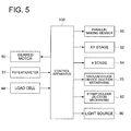
- the load cells 44, the geared motors 50, the potentiometers 51, the parallel making member 60, the XY stage 62, the ⁇ stage 64, the vacuum chuck device 70 (suction mechanism), the stamp holder (suction mechanism), and the light source 90 are connected to a control apparatus 100.
- the control apparatus 100 is adapted to control the operations of these components.
- the control apparatus 300 is adapted to control the operation (rotation) of the geared motors 50 based on the output value of the load cells 44 and the potentiometers 51.
- the glass substrate 3 is mounted on the vacuum chuck device 70, and further, air is sucked through the connection groove 72 so that the glass substrate 3 is made to be attracted and fixed on the vacuum chuck device 70.
- a predetermined amount of a resin 5A is dropped on the glass substrate 3.
- the parallel making member 60, the XY stage 62, and the ⁇ stage 64 are controlled by the control apparatus 100 in such a way that a lower surface of the sub master 20 and a top surface of the glass substrate 3 are made parallel (preliminary process).
- the position of the glass substrate 3 is controlled such that the glass substrate 3 is moved to a specified position in relation to the sub master 20 and the glass substrate 3 is held at the specified position
- the geared motors 50 are operated to extend a shaft 52 upward so as to move a stage 40 upward.
- the control apparatus 100 controls the operation of the geared motors 50 based on the output value of the potentiometers 51 such that the stage 40 is moved upward to a position with a predetermined height
- the position with the predetermined height of the stage 40 to be moved upward is set beforehand in the control apparatus 100. Accordingly, as shown in Fig. 7 , the control apparatus 100 operates the geared motors 50 until the vacuum chuck device 70 arrives at a reference position S, and when the vacuum chuck device 70 has arrived at the reference position S, the control apparatus 100 stop the operating of the geared motors 50 (position control process).
- the resin 5A spreads gradually in response to the pressing force of the glass substrate 3, and as shown in Fig. 6 , the resin 5A is filled up in the cavities 24 of the sub master 20. Then, while the stage 40 is kept being held at a location corresponding to the reference position S, the light source 90 is made to turn on in such a way that as shown in Fig. 8 , light is irradiated to the resin 5A through the light transmissive sub master 20, whereby the resin 5A is hardened (light irradiating process).
- the stage 40 is kept being held at the position with the predetermined height, when the hardened resin 5A shrinks, the glass substrate 3 does not follow the shrinkage.
- the stage 40 is kept being held at the position with the predetermined height, when the hardened resin 5A shrinks, the glass substrate 3 does not follow the shrinkage.
- distortion may be caused inside the resin 5A, or the surface configuration of the cavities 24 may be transferred insufficiently to the resin 5A. That is, owing to change in the pressing force due to the shrinkage, the transfer of the surface configuration may become insufficient.
- Fig. 13 shows change of the pressure to the resin 5A when the stage 40 is held at the position with the predetermined height after the abovementioned position control.
- the glass substrate 3 is subjected to pressure control in such a way that the pressing force of the glass substrate 3 to the sub master 20 is held at a predetermined pressure.
- the pressure is controlled to be held at a predetermined pressure (PC), whereby the above problems can be suppressed.
- the pressing force of the glass substrate 3 to the sub master 20 substantially means herein the pressing force to press the resin 5A toward the sub master 20.
- the geared motors 50 are operated again so as to extend a shaft 52 upward and to move the stage 40 upward.
- the control apparatus 100 controls the operation of the geared motors 50 based on the output value of the load cells 44 so that the stage 40 is moved upward while the pressing force of the stage 40 to the sub master 20 is being held at a predetermined pressure.
- the pressing force ofthe stage 40 to the sub master 20 is set beforehand in the control apparatus 100 in such a way that he control apparatus 00 controls the operation of the geared motors 50 based on the output value received from the load cells 44 so that the pressing force of the stage 40 to the sub master 20 is held at the predetermined pressure (pressure control process).
- control apparatus 100 also controls the parallel making member 60, the XY stage 62, and the ⁇ stage 64 based on the output value of the potentiometers 51 and the load cells 44 so that the parallelism between the glass substrate 3 and the sub master 20 the equal load to the resin 5A are held at a constant respectively.
- the light source 90 is made to switch off to stop irradiating light to the resin 5A.
- the light irradiation to the resin 5A may be stopped before the pressure control process.
- the geared motors 50 are operated to retract the shafts 52 downward so as to move the stage 40 downward, whereby the hardened resin 5A is released together with the glass substrate 3 from the sub master 20 (release process).
- the wafer lens 1 in which a plurality af convex lens portions 5 is formed on the glass substrate 3 can be manufactured.
- the glass substrate 3 is subjected to a position control in such a way that the vacuum chuck device 70 is moved upward to the reference position S based on the output value of the potentiometers 51 and held at the reference position S.
- the glass substrate 3 is subjected to a pressure control (load control) in such a way that the pressing force of the stage 40 to the sub master 20 is held at a predetermined pressure based on the output value of the load cells 44. Namely, the control of the glass substrate 3 is changed from the position control to the pressure control before and after the light irradiation to the resin 5A.
- the resin 5A can be compulsorily pressed with a predetermined pressure toward the cavities 24 of the sub master 20 while following the volume change of the resin 5A.
- the resin 5A it becomes possible to suppress the following problems, distortion is caused inside the resin 5A, and the surface configuration of the cavities 24 is transferred insufficiently to the resin 5A. Accordingly, it becomes possible to suppress the lowering of the transferability from the cavities of the sub master 20 to the resin 5A.
- the position control and the pressure control for the glass substrate 3 may be conducted simultaneously. That is, when the glass substrate 3 is moved to a specified position, the glass substrate 3 is subjected to a pressure control such that the pressing force of the glass substrate 3 to the sub master 20 is held below a predetermined pressure.
- Such a speed control may be performed not only in the stage of the abovementioned pressure control at the time of pressing but also in the stage of the position control, with this, it may be possible to obtain the effect that the unevenness of resin can be suppressed.
- control apparatus 100 controls the movement of the stage 40 based on the output value of the potentiometers 51
- the control apparatus 100 controls the operation of the geared motors 50 while always referring the output value of the load cells 44 such that the pressing force of the stage 40 to the sub master 20 is held at a predetermined pressure or less. In this case, it is possible to prevent the resin 5A from being applied with a load more than needed, whereby the deformation of the sub master 20 can be prevented surely.
- the operation of the geared motors 50 may be controlled on real time basis based on the output value of the load cells 44. Namely, a predetermined pressing force set beforehand for the control apparatus 100 is made as a threshold value, and when the control apparatus 100 receives the output value of the load cells 44, if the output value becomes the threshold value or more, the operation of the geared motors 50 is stopped, and then if the output value of the load cells 44 becomes less that threshold value, the operation of the geared motors 50 is resumed.
- Embodiment 2 differs from Embodiment 1 in respect of the following points, and is made as the same as Embodiment 1 other than the points.
- a sub master 20 is attracted and fixed to a vacuum chuck device 70.
- a vacuum chuck device 110 is fixed to the protrusion portion 34 of the base 32.
- the vacuum chuck device 110 is constructed with a light transmissive member, and when a light source 90 is made to turn on, light is adapted to transmit through the vacuum chuck device 110.
- communicating groove 112 are formed in a form of concentric circles.
- a suction mechanism (not shown in the drawing) is connected such that air is sucked through the communicating grooves 112 by the operation of the suction mechanism, whereby a member is attracted and fixed under the vacuum chuck device 110.
- a glass substrate 3 is attracted and fixed by the vacuum chuck device 110.
- the vacuum chuck device 110 (suction mechanism) is connected to the control apparatus 100 so that its operation is controlled by the control apparatus 100.
- the glass substrate 3 is installed to the vacuum chuck device 110, and the sub master 20 is installed to the vacuum chuck device 70, and then a predetermined amount of the resin 5A is dropped on the sub master 20.
- the sub master 20 is subjected to the position control in such a way that the sub master 20 is moved to a specified position in relation to the glass substrate 3, and the sub master 20 is held at the specified position (the mechanical operations in this case are the same as those in Embodiment 1 fundamentally).
- the sub master 20 is subjected to the pressure control such that the pressing force of the sub master 20 to the glass substrate 3 is held at a predetermined pressure (the mechanical movements in this case are the same as those in Embodiment 1 fundamentally).
- the installation position of the glass substrate 3 and the installation position of the sub master 20 are reversed, and the control of the sub master 20 is changed from the position control to the pressure control before and after the light irradiation to the resin 5A.
- the control of the sub master 20 is changed from the position control to the pressure control before and after the light irradiation to the resin 5A.
- the position control and the pressure control for the sub master 20 may be conducted simultaneously. That is, when the sub master 20 is moved to a specified position, the sub master 20 is subjected to a pressure control such that the pressing force of the sub master 20 to the glass substrate 3 is held below a predetermined pressure (the mechanical movements in this case are the same as those in Modified Embodiment 1 in Embodiment 1 fundamentally).
- the predetermined pressure set up in the pressure control process may be set to pressure values formed in multiple stages as progress of the hardening of resin.
- the control method of the predetermined pressure is not limited to a method to control the predetermined pressure in a form of discontinuous straight lines as shown in Fig. 15 , but also may be a method to control it continuously, for example, based on a pressure curve determined experientially beforehand.
- the pressure control may be conducted in such a way that a predetermined amount of movement, that is, a ON and Off pressure control is conducted multiple times so as to make the pressure become close stepwise to a desired pressure value.
- a predetermined amount of movement that is, a ON and Off pressure control is conducted multiple times so as to make the pressure become close stepwise to a desired pressure value.
- a table of desired pressure values is memorized beforehand, and the pressure may be controlled to become a corresponding pressure value with reference to the table based on a pressure value detected by the load cell.
Landscapes
- Engineering & Computer Science (AREA)
- Mechanical Engineering (AREA)
- Physics & Mathematics (AREA)
- Manufacturing & Machinery (AREA)
- General Physics & Mathematics (AREA)
- Optics & Photonics (AREA)
- Casting Or Compression Moulding Of Plastics Or The Like (AREA)
- Moulds For Moulding Plastics Or The Like (AREA)
Abstract
Description
- The present invention relates to a manufacturing apparatus and manufacturing method of a wafer lens.
- Conventionally, in the manufacturing field of an optical lens, examined is a technique to obtain an optical lens with high heat resistance by providing a lens portion composed of a hardenable resin to a glass substrate (for example, refer to Patent Document 1). As an example of the manufacturing method of an optical lens with the application of this technique, proposed is a method of forming a plurality of optical lenses composed of a hardenable resin on a glass substrate which is a so-called "a wafer lens" and thereafter cutting the glass substrate for each lens portion.
- The manufacturing method of a wafer lens in the case of employing a light hardenable resin as a hardenable resin is explained briefly as follows. As shown in
Fig. 11 , aglass substrate 3 on which aresin 5A has been dropped is sucked and fixed on avacuum chuck device 70 and then moved upward by thevacuum chuck device 70 toward amolding die 20 arranged above theglass substrate 3, whereby theresin 5A is pressed on the molding die 20 (refer to an arrow mark). Themolding die 20 is a light transmissivemold having cavities 24, and is held by and fixed on astamp holder 80. - Then, as shown in
Fig. 12 , while the position of theglass substrate 3 with a height is being held as it is, light is irradiated to theresin 5A filled up in thecavities 24 from the upper portion of themolding die 20 so that theresin 5A is hardened. Thereafter, while theglass substrate 3 is being moved downward, theresin 5A is released from themolding die 20. As a result, a wafer lens in which a plurality of lens portions (5A) is formed on theglass substrate 3 can be manufactured. -
- Patent Document 1: Patent No.
3926380 - However, in the process of hardening the
resin 5A by irradiating light inFig. 12 , theresin 5A may cause shrinkage by being irradiated with light. In this case, in the conventional manufacturing method represented byFig. 11 andFig. 12 , theglass substrate 3 is merely moved upward to a predetermined height and the glass substrate is held at the position. Therefore, even if the configuration of the cavities is precisely transferred onto theresin 5A as illustrated at the section of the cavities inFig. 12 before the irradiating of light, since theresin 5A shrink during or after the irradiating of light, there is possibility that the transferability from themolding die 20 to theresin 5A lowers (there is possibility that the lens configuration of the lens portion deviates from the design value). - Therefore, a main object of the present invention is to provide a wafer lens manufacturing apparatus and manufacturing method which can suppress the lowering of the transferability from a molding die to resin.
- The first embodiment of a wafer lens manufacturing apparatus for solving the above problems is a manufacturing apparatus of wafer lens having a plurality of lens portions made of a light hardenable resin on one surface of a substrate, and the manufacturing apparatus is characterized by comprising:
- a molding die holding means for holding a molding die having a plurality ofmolding die surfaces corresponding to an optical surface configuration ofthe abovementioned lens portions;
- a substrate holding means for holding the abovementioned substrate;
- a resin arranging means for arranging a light hardenable resin on at least one of one surface of the substrate and the molding surfaces of the abovementioned molding die;
- a moving means for moving the abovementioned molding die relatively to the one surface of the substrate;
- a pressure detecting means for detecting a pressing force caused on the substrate by the movement of mowing means through the light hardenable resin arranged against the molding die;
- a light irradiating means for irradiates light to advance the hardening of the light hardenable resin; and
- a pressure control means for controlling the pressing force which changes in according with the hardening of the light hardenable resin which progresses with the light irradiation, based on the detection result of the above-mentioned pressure detecting means.
- The second embodiment of the wafer lens manufacturing apparatus for solving the abovementioned problems is characterized in that the above-mentioned pressure control means controls to hold the pressing force at a predetermined constant pressure value.
- The third embodiment of the wafer lens manufacturing apparatus for solving the abovementioned problems is characterized in that the above-mentioned pressure control means controls to make the pressing force to a predetermined constant pressure value or less.
- The fourth embodiment of the wafer lens manufacturing apparatus for solving the abovementioned problems is characterized in that the manufacturing installation comprises a position detecting means for detecting the position of the substrate, the relative position of the molding die to one surface of the substrate by the moving means is held at a predetermined position based on a detection result of the position detecting section, and the above-mentioned pressure control means conducts pressure control at the predetermined position.
- The fifth embodiment of the wafer lens manufacturing apparatus for solving the abovementioned problems is characterized in that the pressure control by the pressure control means is an ON and OFF control to control preliminarily-set multiple pressure values stepwise.
- The sixth embodiment of a wafer lens manufacturing method for solving the abovementioned problems is a manufacturing method of wafer lens having a plurality of lens portions formed by molding and hardening a light hardenable resin on one surface of a substrate, and the manufacturing method is characterized by comprising:
- an arranging process for arranging a light hardenable resin on at least one of molding surfaces of a molding die having a plurality of molding surfaces corresponding to an optical configuration of the lens portions and one surface of the substrate;
- a pressing process for pressing the substrate through the light hardenable resin arranged against the molding die by moving the molding die relatively against one surface of the substrate;
- a light irradiating process for irradiating light to advance the hardening of the light hardenable resin; and
- a pressure control process for controlling the pressing force in the pressing process which changes in according with the hardening of the light hardenable resin which progresses with the light irradiation.
- The seventh embodiment of a wafer lens manufacturing method for solving the abovementioned problems is characterized in that in the abovementioned pressure control process, the pressing force is controlled so as to be held at a predetermined constant pressure value.
- The eighth embodiment of a wafer lens manufacturing method for solving the abovementioned problems is characterized in that in the above-mentioned pressure control process, the pressing force is controlled to be made to a predetermined constant pressure value or less.
- According to the wafer lens manufacturing apparatus and manufacturing method of the present invention, since the pressing force of the molding die to the substrate which changes due to hardening caused by the light irradiation against a light hardenable resin is controlled, even if the light hardenable resin shrinks, it becomes possible to suppress the lowering of the transferability from the molding die to the light hardenable resin.
-
-
Fig. 1 is a perspective view showing an outline structure of a wafer lens relating toEmbodiment 1. -
Fig. 2 is a drawing showing an outline structure of water lens manufacturing apparatus relating toEmbodiment 1 and is a drawing showing a condition before a molding die (sub master) is filled up with resin. -
Fig. 3 is a perspective view showing an outline structure of a sub master (molding die) relating toEmbodiment 1. -
Fig. 4 is a perspective view showing an outline structure of a master (mother die) of the sub master ofFig. 3 . -
Fig. 5 is a block diagram for explaining schematically a control constitution of the wafer lens manufacturing apparatus relating toEmbodiment 1. -
Fig. 6 is a drawing showing an outline structure of a wafer lens manufacturing apparatus relating toEmbodiment 1 and is a drawing showing a condition when a molding die (sub master) has been filled up with resin. -
Fig. 7 is a drawing in which a part ofFig. 2 is expanded. -
Fig. 8 is a drawing in which a part ofFig. 6 is expanded. -
Fig. 9 is a drawing showing an outline structure of a wafer lens manufacturing apparatus relating to Embodiment 2 and is a drawing showing a condition before a molding die (sub master) is filled up with resin. -
Fig. 10 is a drawing showing an outline structure of a wafer lens manufacturing apparatus relating to Embodiment 2 and is a drawing showing a condition when a molding die (sub master) has been filled up with resin. -
Fig. 11 is a drawing for explaining schematically prior art and is a drawing showing a condition before a molding die is filled up with resin. -
Fig. 12 is a drawing for explaining schematically prior art and is a drawing showing a condition when a molding die has been filled up with resin. -
Fig. 13 is a drawing showing change of pressure for resin when a stage is held with a predetermined height. -
Fig. 14 is a drawing showing change of pressure for resin when a pressing force is set at a predetermined pressure or less. -
Fig. 15 is a drawing showing change of pressure for resin when a pressing force is set to pressure values in multiple stages in accordance with the progress of hardening of resin. -
Fig. 16 is a drawing showing change of pressure for resin when an ON and OFF pressure control is conducted multiple times such that a pressing force is controlled to become desired pressure values stepwise. - Next, desirable embodiments of the present invention will be described with reference to drawings.
- As shown in
Fig. 1 , awafer lens 1 comprises a circle-shaped glass substrate 3 and two or a plurality oflens portions 5. Theglass substrate 3 is an example of a substrate. On the surface of theglass substrate 3, the plurality ofconvex lens portions 5 are arranged in an array form. On a surface of an optical surface of aconvex lens portion 5, microscopic structures such as diffractive grooves and stepped portions may be formed. - The
convex lens portion 5 is made of aresin 5A. Theresin 5A is a light hardenable resin. As such a light hardenable resin, for example, an acrylic resin, an allyl ester resin, and the like may be employed, and these resins can be hardened by the reaction of radical polymerization. As another light hardenable resin, for example, an epoxy type resin may be employed and such a resin can be hardened by the reaction of cationic polymerization. - Next, the following explanation is made about a wafer lens manufacturing apparatus (30) used at the time of manufacturing a
wafer lens 1. - As shown in
Fig. 2 , the waferlens manufacturing apparatus 30 comprises abase 32. On an upper portion of thebase 32, formed is aprotrusion section 34 which protrudes toward inside.Guides 36 are provided so as to stand between a floor portion of thebase 32 and theprotrusion section 34. Between the guides, astage 40 is provided. Thestage 40 is provided with throughholes 42 and the guides 35 are arranged so as to pass through the respective throughholes 42. - On the
base 32 and beneath thestage 40, gearedmotors 50 are provided. The gearedmotors 50 incorporate a potentiometer 51 (refer toFig. 5 ) respectively. Further, each of the gearedmotors 50 is linked with ashaft 52. On the lower side of thestage 40,load cells 44 are provided such that theload cells 44 are brought in contact with the tip oftheshafts 52 by the weight of thestage 40. In the waferlens manufacturing apparatus 30, theshafts 52 are adapted to move upward and downward by the operation of the gearedmotors 50, and with this movement, thestage 40 can be moved upward and downward while being guided withguides 36. - On the
stage 40, formed is aconcave portion 46 which is shaped in almost a hemisphere configuration. In theconcave portion 46, aparallel making member 60 is embedded. Theparallel making member 60 is adapted to be able to oscillate in theconcave portion 46 as with a bowl floating on water surface. On the parallel makingmember 60, provided are aXY stage 62 and aθ stage 64. TheXY stage 62 is adapted to be movable on a XY flat surface (a two-dimensional flat surface), and theθ stage 64 is adapted to be rotatable around its central portion as a rotation axis. - On the
XY stage 62 and theθ stage 64, avacuum chuck device 70 is installed. On thevacuum chuck device 70, communicatinggrooves 72 are formed in concentric circles. To the communicatinggrooves 72, a suction mechanism (not shown in the drawing) is connected such that air is sucked through the communicatinggrooves 72 by the operation of the suction mechanism, whereby a member is attracted and fixed on thevacuum chuck device 70. In this embodiment, aglass substrate 3 is attracted and fixed by thevacuum chuck device 70. - On an upper portion of the
base 32, astamp holder 80 is fixed. To thestamp holder 80, a light transmissive sub master 20 (molding die) is adapted to be fixed. More in detail, on end portions of thestamp holder 80, communicatinggrooves 82 are formed in concentric circles and, to the communicatinggrooves 82, a suction mechanism (not shown in the drawing) is connected. As with the time that thevacuum chuck device 70 operates, when the suction mechanism operates, air is sucked through the communicatinggrooves 82, whereby thesub master 20 is attracted and fixed to thestamp holder 80. Above the sub master, alight source 90 is provided such that when the light source is turned on, light is irradiated toward thesub master 20. - As shown in
Fig. 2 andFig. 3 , thesub master 20 mainly is composed of amolding section 22 and abase material 26. On themolding section 22, a plurality of cavities (concave portions) is shaped in an array form. - The surface (die surface) configuration of each of the
cavities 24 is made a negative configuration corresponding to aconvex lens portion 5 in awafer lens 1. Therefore, in this drawing, the surface configuration is made concave in an approximately hemisphere configuration. - The
molding section 22 is made of aresin 22A. As theresin 22A, preferable is a resin with a good mold-release characteristic, especially preferable is a transparent resin. Such a resin is excellent in a point capable of releasing a mold without the application of a mold releasing agent. As such aresin 22A, any one of a light curable resin, a thermo-hardening resin, and a thermoplastic resin may be employable. - The
base material 26 is used as a lining material such that in the case where only themolding section 22 of thesub master 20 is inferior in strength, thebase material 26 pasted on themolding section 22 increase the strength of thesub master 20 so as to allow thesub master 20 to conduct molding repeatedly. - The
base material 26 may be structured with a different material from themolding section 22, or may be structured integrally with the same material as themolding section 22. In the case where thebase material 26 is structured with a different material from themolding section 22, as the material of thebase material 26, any materials having smoothness, such as quartz, silicon wafer, metal, glass, resin, ceramics, and the like may be employed. Here, to structure thebase material 26 integrally with the same material as themolding section 22 is to constitute thesub master 20 only with themolding section 22. - In the manufacturing of a wafer lens 1 (the molding of convex lens portions 5), the
sub master 20 shown inFig. 3 is mainly used. However, in addition, amaster 10 shown inFig. 4 is also used. That is, themaster 10 is a mother die used at the time of manufacturing thesub master 20, and thesub master 20 is a molding die used at the time of molding a wafer lens 1 (convex lens portions 5). Thesub master 20 is used two or more times for mass-manufacturing awafer lens 1, and is different from amaster 10 in terms of the purpose of use, frequency in use, and the like. - As shown in
Fig. 4 , in themaster 10, a plurality ofconvex portions 14 are formed in an array form on abase section 12 shaped in a rectangular body. Theconvex portions 14 are portions corresponding to theconvex lens portions 5 of thewafer lens 1, and are protruded in an approximately hemisphere configuration respectively. The outline shape of themaster 10 may be a rectangular in this way, or may be a circular. - The surface (die surface) configuration of each of the
convex portions 14 is made a positive configuration corresponding to the optical surface configuration of each ofconvex lens portions 5 which are molded and transferred on aglass substrate 3. - As a material of the
master 10, in the case where an optical surface configuration is created with mechanical processing such as cutting, grinding, and the like, metal or metallic glass may be employed. As a classification of the material, iron-based materials and their alloys may be employed. Examples of the iron-based materials include hot die steel, cold die steel, plastic die steel, high-speed tool steel, rolled steel for general structure, carbon steel for machine structure, chrome molybdenum steel, stainless steel and the like. In the above, examples of the plastic die steel include pre-hardened steel, quenched tempered steel, and aging treated steel. Examples of the pre-hardened steel include a SC type steel, a SCM type steel, and a SUS type steel. More concretely, examples of the SC type steel include PXZ, examples of the SCM type steel include HPM2, HPM7, PX5, and IMPAX, and examples of the SUS type steel include HPM38, HPM77, S-STAR, G-STAR, STAVAX, RAMAX-S, and PSL. Further, examples of the iron-based alloy are disclosed in Japanese Unexamined Patent Publication No.2005-113161 2005-206913 10-219373 2000-176970 master 10, or may cover only a surface of specifically an optical transfer surface by a method, such as plating and spattering. - As shown in
Fig. 5 , theload cells 44, the gearedmotors 50, thepotentiometers 51, the parallel makingmember 60, theXY stage 62, theθ stage 64, the vacuum chuck device 70 (suction mechanism), the stamp holder (suction mechanism), and thelight source 90 are connected to acontrol apparatus 100. Thecontrol apparatus 100 is adapted to control the operations of these components. Specifically, in this embodiment, the control apparatus 300 is adapted to control the operation (rotation) of the gearedmotors 50 based on the output value of theload cells 44 and thepotentiometers 51. - Subsequently, a manufacturing method of a
wafer lens 1 by the use of the waferlens manufacturing apparatus 30 will be explained. - As shown in
Fig. 2 , first, while thesub master 20 is made to be attracted and fixed to thestamp holder 80, theglass substrate 3 is mounted on thevacuum chuck device 70, and further, air is sucked through theconnection groove 72 so that theglass substrate 3 is made to be attracted and fixed on thevacuum chuck device 70. Successively, a predetermined amount of aresin 5A is dropped on theglass substrate 3. Then, the parallel makingmember 60, theXY stage 62, and theθ stage 64 are controlled by thecontrol apparatus 100 in such a way that a lower surface of thesub master 20 and a top surface of theglass substrate 3 are made parallel (preliminary process). - In this status, as shown in
Fig. 6 , the position of theglass substrate 3 is controlled such that theglass substrate 3 is moved to a specified position in relation to thesub master 20 and theglass substrate 3 is held at the specified position - More in detail, the geared
motors 50 are operated to extend ashaft 52 upward so as to move astage 40 upward. In this case, thecontrol apparatus 100 controls the operation of the gearedmotors 50 based on the output value of thepotentiometers 51 such that thestage 40 is moved upward to a position with a predetermined height - In the wafer
lens manufacturing apparatus 30, the position with the predetermined height of thestage 40 to be moved upward is set beforehand in thecontrol apparatus 100. Accordingly, as shown inFig. 7 , thecontrol apparatus 100 operates the gearedmotors 50 until thevacuum chuck device 70 arrives at a reference position S, and when thevacuum chuck device 70 has arrived at the reference position S, thecontrol apparatus 100 stop the operating of the geared motors 50 (position control process). - As a result, the
resin 5A spreads gradually in response to the pressing force of theglass substrate 3, and as shown inFig. 6 , theresin 5A is filled up in thecavities 24 of thesub master 20. Then, while thestage 40 is kept being held at a location corresponding to the reference position S, thelight source 90 is made to turn on in such a way that as shown inFig. 8 , light is irradiated to theresin 5A through the lighttransmissive sub master 20, whereby theresin 5A is hardened (light irradiating process). - Here, at the time that the
resin 5A is hardened (during the hardening of theresin 5A or thereafler), if thestage 40 is kept being held at the position with the predetermined height, when thehardened resin 5A shrinks, theglass substrate 3 does not follow the shrinkage. As a result, there is a possibility that distortion may be caused inside theresin 5A, or the surface configuration of thecavities 24 may be transferred insufficiently to theresin 5A. That is, owing to change in the pressing force due to the shrinkage, the transfer of the surface configuration may become insufficient. - Incidentally,
Fig. 13 shows change of the pressure to theresin 5A when thestage 40 is held at the position with the predetermined height after the abovementioned position control. - As can be understood from this, if the
stage 40 is merely kept being held at the position with the predetermined height, hardening shrinkage arises as the resin is being hardened in the light irradiating process, whereby the pressure becomes lower as shown with a broken line. As a result, since the molded surface does not fit sufficiently to the molding die, the transferability may be deteriorated, or birefringence may be caused inside by residual stress so that an optical characteristic may be degraded. - Then, in this embodiment, if the
light source 90 has been made to turn on for a predetermined time period so as to irradiate a predetermined amount of light to theresin 5A, theglass substrate 3 is subjected to pressure control in such a way that the pressing force of theglass substrate 3 to thesub master 20 is held at a predetermined pressure. With this, as shown inFig. 14 , for example, the pressure is controlled to be held at a predetermined pressure (PC), whereby the above problems can be suppressed. - As can be seen from
Fig. 6 andFig. 8 , since theresin 5A is provided between theglass substrate 3 and thesub master 20, the pressing force of theglass substrate 3 to thesub master 20 substantially means herein the pressing force to press theresin 5A toward thesub master 20. - More in detail, the geared
motors 50 are operated again so as to extend ashaft 52 upward and to move thestage 40 upward. In this case, thecontrol apparatus 100 controls the operation of the gearedmotors 50 based on the output value of theload cells 44 so that thestage 40 is moved upward while the pressing force of thestage 40 to thesub master 20 is being held at a predetermined pressure. - In the wafer
lens manufacturing apparatus 30, the pressing force ofthestage 40 to thesub master 20 is set beforehand in thecontrol apparatus 100 in such a way that he control apparatus 00 controls the operation of the gearedmotors 50 based on the output value received from theload cells 44 so that the pressing force of thestage 40 to thesub master 20 is held at the predetermined pressure (pressure control process). - In this case, the
control apparatus 100 also controls the parallel makingmember 60, theXY stage 62, and theθ stage 64 based on the output value of thepotentiometers 51 and theload cells 44 so that the parallelism between theglass substrate 3 and thesub master 20 the equal load to theresin 5A are held at a constant respectively. - Thereafter, the
light source 90 is made to switch off to stop irradiating light to theresin 5A. The light irradiation to theresin 5A may be stopped before the pressure control process. Then, the gearedmotors 50 are operated to retract theshafts 52 downward so as to move thestage 40 downward, whereby thehardened resin 5A is released together with theglass substrate 3 from the sub master 20 (release process). As a result, thewafer lens 1 in which a plurality afconvex lens portions 5 is formed on theglass substrate 3 can be manufactured. - According to this embodiment mentioned above, at the stage before light is irradiated to the
resin 5A, theglass substrate 3 is subjected to a position control in such a way that thevacuum chuck device 70 is moved upward to the reference position S based on the output value of thepotentiometers 51 and held at the reference position S. On the other hand, at the stage after light has been irradiated to theresin 5A, theglass substrate 3 is subjected to a pressure control (load control) in such a way that the pressing force of thestage 40 to thesub master 20 is held at a predetermined pressure based on the output value of theload cells 44. Namely, the control of theglass substrate 3 is changed from the position control to the pressure control before and after the light irradiation to theresin 5A. - Therefore, owing to the light irradiation to the
resin 5A, even if theresin 5A causes hardening shrinkage, theresin 5A can be compulsorily pressed with a predetermined pressure toward thecavities 24 of thesub master 20 while following the volume change of theresin 5A. As a result, it becomes possible to suppress the following problems, distortion is caused inside theresin 5A, and the surface configuration of thecavities 24 is transferred insufficiently to theresin 5A. Accordingly, it becomes possible to suppress the lowering of the transferability from the cavities of thesub master 20 to theresin 5A. - In the position control process, the position control and the pressure control for the
glass substrate 3 may be conducted simultaneously. That is, when theglass substrate 3 is moved to a specified position, theglass substrate 3 is subjected to a pressure control such that the pressing force of theglass substrate 3 to thesub master 20 is held below a predetermined pressure. - The reason is that when a resin with high viscosity, for example, a resin material having a viscosity of 10000 mPa·S or more is employed, in the case where a pressure control is not performed, there is a problem that since a pressure becomes high too much as shown with a broken line in
Fig. 14 , the sub master may deform or pressure distribution in the resin may become uneven. Then, with a pressure control that the rising speed of the stage is made slow so as to prevent beforehand the pressing force from becoming a predetermined pressure (PL) or more, such a problem may be suppressed. - Such a speed control may be performed not only in the stage of the abovementioned pressure control at the time of pressing but also in the stage of the position control, with this, it may be possible to obtain the effect that the unevenness of resin can be suppressed.
- More in detail, in addition to the control that the
control apparatus 100 controls the movement of thestage 40 based on the output value of thepotentiometers 51, thecontrol apparatus 100 controls the operation of the gearedmotors 50 while always referring the output value of theload cells 44 such that the pressing force of thestage 40 to thesub master 20 is held at a predetermined pressure or less. In this case, it is possible to prevent theresin 5A from being applied with a load more than needed, whereby the deformation of thesub master 20 can be prevented surely. - In the pressure control process, the operation of the geared
motors 50 may be controlled on real time basis based on the output value of theload cells 44. Namely, a predetermined pressing force set beforehand for thecontrol apparatus 100 is made as a threshold value, and when thecontrol apparatus 100 receives the output value of theload cells 44, if the output value becomes the threshold value or more, the operation of the gearedmotors 50 is stopped, and then if the output value of theload cells 44 becomes less that threshold value, the operation of the gearedmotors 50 is resumed. - Embodiment 2 differs from
Embodiment 1 in respect of the following points, and is made as the same asEmbodiment 1 other than the points. - In this Embodiment 2, the installation position of the
glass substrate 3 and the installation position of thesub master 20 are reversed. More in detail, as shown inFig. 9 , asub master 20 is attracted and fixed to avacuum chuck device 70. Avacuum chuck device 110 is fixed to theprotrusion portion 34 of thebase 32. Thevacuum chuck device 110 is constructed with a light transmissive member, and when alight source 90 is made to turn on, light is adapted to transmit through thevacuum chuck device 110. On thevacuum chuck device 110, communicatinggroove 112 are formed in a form of concentric circles. To the communicatinggrooves 112, a suction mechanism (not shown in the drawing) is connected such that air is sucked through the communicatinggrooves 112 by the operation of the suction mechanism, whereby a member is attracted and fixed under thevacuum chuck device 110. In this embodiment, aglass substrate 3 is attracted and fixed by thevacuum chuck device 110. The vacuum chuck device 110 (suction mechanism) is connected to thecontrol apparatus 100 so that its operation is controlled by thecontrol apparatus 100. - At the time of manufacturing the
wafer lens 1 by the use of the waferlens manufacturing apparatus 30 relating to this embodiment 2, in a preliminary process, theglass substrate 3 is installed to thevacuum chuck device 110, and thesub master 20 is installed to thevacuum chuck device 70, and then a predetermined amount of theresin 5A is dropped on thesub master 20. - In the position control process, as shown in
Fig. 10 , thesub master 20 is subjected to the position control in such a way that thesub master 20 is moved to a specified position in relation to theglass substrate 3, and thesub master 20 is held at the specified position (the mechanical operations in this case are the same as those inEmbodiment 1 fundamentally). - In the light irradiating process, light is irradiated to the
resin 5A through the light transmissivevacuum chuck device 110 and theglass substrate 3 so as to harden theresin 5A. - In the pressure control process, the
sub master 20 is subjected to the pressure control such that the pressing force of thesub master 20 to theglass substrate 3 is held at a predetermined pressure (the mechanical movements in this case are the same as those inEmbodiment 1 fundamentally). - According to this embodiment mentioned above, the installation position of the
glass substrate 3 and the installation position of thesub master 20 are reversed, and the control of thesub master 20 is changed from the position control to the pressure control before and after the light irradiation to theresin 5A. Even in this case, as withEmbodiment 1, it becomes possible to suppress the following problems, distortion is caused inside theresin 5A, and the surface configuration of thecavities 24 is transferred insufficiently to theresin 5A. Accordingly, it becomes possible to suppress the lowering of the transferability from the cavities of thesub master 20 to theresin 5A. - In the position control process, the position control and the pressure control for the
sub master 20 may be conducted simultaneously. That is, when thesub master 20 is moved to a specified position, thesub master 20 is subjected to a pressure control such that the pressing force of thesub master 20 to theglass substrate 3 is held below a predetermined pressure (the mechanical movements in this case are the same as those inModified Embodiment 1 inEmbodiment 1 fundamentally). - Further, as shown in
Fig. 15 , the predetermined pressure set up in the pressure control process may be set to pressure values formed in multiple stages as progress of the hardening of resin. Furthermore, the control method of the predetermined pressure is not limited to a method to control the predetermined pressure in a form of discontinuous straight lines as shown inFig. 15 , but also may be a method to control it continuously, for example, based on a pressure curve determined experientially beforehand. - Moreover, as shown in
Fig. 16 , the pressure control may be conducted in such a way that a predetermined amount of movement, that is, a ON and Off pressure control is conducted multiple times so as to make the pressure become close stepwise to a desired pressure value. With this method, it becomes possible to obtain the same effect as that in the method to conduct the control always referring a detected value of the pressure, that is, the same effect as shown inFig. 15 . - Still moreover, a table of desired pressure values is memorized beforehand, and the pressure may be controlled to become a corresponding pressure value with reference to the table based on a pressure value detected by the load cell.
- With the precise control to conduct a pressure control so as to obtain an ideal pressure, high precise transfer is expectable.
-
- 1
- Wafer Lens
- 3
- Glass Substrate
- 5
- Convex Lens Portion
- 5A
- Resin
- 10
- Master
- 12
- Base Portion
- 14
- Convex Portion
- 20
- Sub Master
- 22
- Molding Section
- 22A
- Resin
- 24
- Cavity
- 26
- Base Material
- 30
- Wafer Lens Manufacturing Apparatus
- 32
- Base
- 34
- Protrusion Portion
- 36
- Guide
- 40
- Stage
- 42
- Through Hole
- 44
- Load Cell
- 46
- Concave section
- 50
- Geared Motor
- 51
- Potentiometer
- 52
- Shaft
- 60
- Parallel Making Member
- 62
- XY Stage
- 64
- θ Stage
- 70
- Vacuum Chuck Device
- 72
- Communicating Groove
- 80
- Stamp Holder
- 82
- Communicating Groove
- 90
- Light Source
- 100
- Control Apparatus
- 110
- Vacuum Chuck Device
- 112
- Communicating Groove
Claims (8)
- A manufacturing apparatus of wafer lens having a plurality of lens portions made of a light hardenable resin on one surface of a substrate, and the manufacturing apparatus is characterized by comprising:a molding die holding means for holding a molding die having a plurality of molding die surfaces corresponding to an optical surface configuration of the abovementioned lens portions;a substrate holding means for holding the abovementioned substrate;a resin arranging means for arranging a light hardenable resin on at least one of one surface of the substrate and the molding surfaces of the abovementioned molding die;a moving means for moving the abovementioned molding die relatively to the one surface of the substrate;a pressure detecting means for detecting a pressing force caused on the substrate by movement of moving means through the light hardenable resin arranged against the molding die;a light irradiating means for irradiates light to advance the hardening of the light hardenable resin; anda pressure control means for controlling the pressing force which changes in according with the hardening of the light hardenable resin which progresses with the light irradiation based on the detection result of the above-mentioned pressure detecting means.
- The wafer lens manufacturing apparatus described in claim 1 is characterized in that the abovementioned pressure control means controls to hold the pressing force at a predetermined constant pressure value.
- The wafer lens manufacturing apparatus described in claim 1 is characterized in that the abovementioned pressure control means controls to make the pressing force to a predetermined constant pressure value or less.
- The wafer lens manufacturing apparatus described in any one of claims 1 to 3 is characterized in that the manufacturing installation comprises a position detecting means for detecting the position of the substrate, the relative position of the molding die to one surface of the substrate by the moving means is held at a predetermined position based on a detection result of the position detecting section, and the above-mentioned pressure control means conducts pressure control at the predetermined position.
- The wafer lens manufacturing apparatus described in claim 1 is characterized in that the pressure control by the pressure control means is an ON and OFF control to control preliminarily-set multiple pressure values stepwise.
- A manufacturing method of wafer lens having a plurality of lens portions formed by molding and hardening a light hardenable resin on one surface of a substrate, and the manufacturing method is characterized by comprising:an arranging process for arranging a light hardenable resin on at least one of molding surfaces of a molding die having a plurality of molding surfaces corresponding to an optical configuration of the lens portions and one surface of the substrate;a pressing process for pressing the substrate through the light hardenable resin arranged against the molding die by moving the molding die relatively against one surface of the substrate;a light irradiating process for irradiating light to advance the hardening of the light hardenable resin; anda pressure control process for controlling the pressing force in the pressing process which changes in according with the hardening of the light hardenable resin which progresses with the light irradiation.
- The water lens manufacturing method described in claim 6 is characterized in that in the above-mentioned pressure control process, the pressing force is controlled so as to be held at a predetermined constant pressure value.
- The wafer lens manufacturing method described in claim 6 is characterized in that in the above-mentioned pressure control process, the pressing force is controlled to be made to a predetermined constant pressure value or less.
Applications Claiming Priority (2)
| Application Number | Priority Date | Filing Date | Title |
|---|---|---|---|
| JP2008245616 | 2008-09-25 | ||
| PCT/JP2009/058157 WO2010035540A1 (en) | 2008-09-25 | 2009-04-24 | Apparatus and method for manufacturing wafer lens |
Publications (2)
| Publication Number | Publication Date |
|---|---|
| EP2327527A1 true EP2327527A1 (en) | 2011-06-01 |
| EP2327527A4 EP2327527A4 (en) | 2012-06-13 |
Family
ID=42059549
Family Applications (1)
| Application Number | Title | Priority Date | Filing Date |
|---|---|---|---|
| EP09815958A Withdrawn EP2327527A4 (en) | 2008-09-25 | 2009-04-24 | Apparatus and method for manufacturing wafer lens |
Country Status (3)
| Country | Link |
|---|---|
| EP (1) | EP2327527A4 (en) |
| JP (1) | JP5136648B2 (en) |
| WO (1) | WO2010035540A1 (en) |
Cited By (2)
| Publication number | Priority date | Publication date | Assignee | Title |
|---|---|---|---|---|
| EP2251716A1 (en) * | 2009-05-14 | 2010-11-17 | Fujinon Corporation | Manufacturing method and manufacturing apparatus of shaped article |
| CN103029246A (en) * | 2011-09-30 | 2013-04-10 | 夏普株式会社 | Optical element producing device, optical element producing method, controlling program, and recording medium |
Families Citing this family (2)
| Publication number | Priority date | Publication date | Assignee | Title |
|---|---|---|---|---|
| TWI473141B (en) * | 2012-12-13 | 2015-02-11 | Eternal Materials Co Ltd | A radiation curing apparatus |
| CN115157545B (en) * | 2022-05-26 | 2024-08-23 | 英纳法汽车天窗系统(上海)有限公司 | Mould with error-proofing member and method of use thereof |
Family Cites Families (12)
| Publication number | Priority date | Publication date | Assignee | Title |
|---|---|---|---|---|
| JP2859695B2 (en) * | 1990-05-18 | 1999-02-17 | オリンパス光学工業株式会社 | Method and apparatus for forming aspherical optical element |
| JPH04144719A (en) * | 1990-10-05 | 1992-05-19 | Olympus Optical Co Ltd | Method and device for molding composite optical element |
| JPH06304936A (en) * | 1993-04-23 | 1994-11-01 | Olympus Optical Co Ltd | Molding of composite optical element |
| JPH10219373A (en) | 1997-02-12 | 1998-08-18 | Mitatsukusu:Kk | Copper alloy for press forming die |
| JPH11314231A (en) * | 1998-03-06 | 1999-11-16 | Toshiba Corp | Optical component manufacturing method and apparatus therefor |
| JP2000176970A (en) | 1998-12-21 | 2000-06-27 | Mitsui Mining & Smelting Co Ltd | Manufacturing method of plastic molded products |
| JP2003291159A (en) * | 2002-03-29 | 2003-10-14 | Ricoh Opt Ind Co Ltd | Resin curing method, manufacturing method for resin molding, etc., appliance used for them, and product to be obtained |
| JP2004163490A (en) * | 2002-11-11 | 2004-06-10 | Nippon Sheet Glass Co Ltd | Optical element and its manufacturing method |
| JP3946684B2 (en) | 2003-10-02 | 2007-07-18 | 日本高周波鋼業株式会社 | Hot work tool steel |
| JP2005206913A (en) | 2004-01-26 | 2005-08-04 | Daido Steel Co Ltd | Alloy tool steel |
| JP3926380B1 (en) | 2006-12-07 | 2007-06-06 | マイルストーン株式会社 | Imaging lens |
| US20100027114A1 (en) * | 2006-12-19 | 2010-02-04 | Koninklijke Philips Electronics N.V. | Lens structure and manufacturing method, and the manufacture of shaped polymer articles |
-
2009
- 2009-04-24 JP JP2010530759A patent/JP5136648B2/en not_active Expired - Fee Related
- 2009-04-24 WO PCT/JP2009/058157 patent/WO2010035540A1/en not_active Ceased
- 2009-04-24 EP EP09815958A patent/EP2327527A4/en not_active Withdrawn
Non-Patent Citations (3)
| Title |
|---|
| DATABASE WPI Week 199226 Thomson Scientific, London, GB; AN 1992-214147 XP002674633, -& JP 4 144719 A (OLYMPUS OPTICAL CO LTD) 19 May 1992 (1992-05-19) * |
| DATABASE WPI Week 200419 Thomson Scientific, London, GB; AN 2004-194940 XP002674634, -& JP 2003 291159 A (RICOH KOGAKU KK) 14 October 2003 (2003-10-14) * |
| See also references of WO2010035540A1 * |
Cited By (4)
| Publication number | Priority date | Publication date | Assignee | Title |
|---|---|---|---|---|
| EP2251716A1 (en) * | 2009-05-14 | 2010-11-17 | Fujinon Corporation | Manufacturing method and manufacturing apparatus of shaped article |
| CN103029246A (en) * | 2011-09-30 | 2013-04-10 | 夏普株式会社 | Optical element producing device, optical element producing method, controlling program, and recording medium |
| CN103029246B (en) * | 2011-09-30 | 2015-11-18 | 夏普株式会社 | The manufacturing installation of optical element and manufacture method |
| US9427919B2 (en) | 2011-09-30 | 2016-08-30 | Sharp Kabushiki Kaisha | Optical element producing device, optical element producing method, controlling program, and recording medium |
Also Published As
| Publication number | Publication date |
|---|---|
| EP2327527A4 (en) | 2012-06-13 |
| JP5136648B2 (en) | 2013-02-06 |
| WO2010035540A1 (en) | 2010-04-01 |
| JPWO2010035540A1 (en) | 2012-02-23 |
Similar Documents
| Publication | Publication Date | Title |
|---|---|---|
| US20120068370A1 (en) | Method for Producing Wafer Lens, and Method and Apparatus for Producing Wafer Lens Laminate | |
| JP5147608B2 (en) | Modeling method, manufacturing method of modeled object, and modeling apparatus | |
| CN100471594C (en) | Sheet forming method | |
| EP2327527A1 (en) | Apparatus and method for manufacturing wafer lens | |
| CN1060997C (en) | Optical elements, method and device for manufacture the same | |
| WO2010050290A1 (en) | Wafer lens manufacturing method and wafer lens | |
| CN1715224A (en) | Method and apparatus for producing an optical element and substrate thereof | |
| TWI503580B (en) | Manufacturing method of molding tool, wafer lens, and optical lens | |
| KR20100015588A (en) | Method of producing glass molding product and mold press molding device | |
| JP4586940B2 (en) | Optical component manufacturing method, optical component manufacturing apparatus, and wafer lens manufacturing method | |
| KR20020034922A (en) | Method of manufacturing a microlens and a microlens array | |
| JP2011051132A (en) | Method and apparatus for manufacturing optical component | |
| CN1080175C (en) | Method for manufacturing optical blank and optical parts based on pressure formed and pressure mould | |
| JP2010280565A (en) | Mold press forming apparatus and method for manufacturing optical element | |
| JP2010107879A (en) | Method of manufacturing wafer lens, wafer lens, and device for manufacturing wafer lens | |
| JP2008110610A (en) | Micromachining method and micromachining substrate | |
| JP4786085B2 (en) | Apparatus for molding minute parts and molding method of minute parts | |
| JP4119474B2 (en) | Microfabrication method and microfabrication substrate | |
| JP5809945B2 (en) | Optical element manufacturing method and optical element manufacturing apparatus | |
| US12479132B2 (en) | Resin shaping mold and resin shaping method | |
| JP4951394B2 (en) | Optical element molding method | |
| JP2011051129A (en) | Method of manufacturing optical component | |
| JPH1044255A (en) | Microstructure and method and apparatus for manufacturing the same | |
| Bauer et al. | Tooling for injection molded optics | |
| JPH1134067A (en) | Manufacture of mold, mold release mechanism, and pressurizing device |
Legal Events
| Date | Code | Title | Description |
|---|---|---|---|
| PUAI | Public reference made under article 153(3) epc to a published international application that has entered the european phase |
Free format text: ORIGINAL CODE: 0009012 |
|
| 17P | Request for examination filed |
Effective date: 20110316 |
|
| AK | Designated contracting states |
Kind code of ref document: A1 Designated state(s): AT BE BG CH CY CZ DE DK EE ES FI FR GB GR HR HU IE IS IT LI LT LU LV MC MK MT NL NO PL PT RO SE SI SK TR |
|
| AX | Request for extension of the european patent |
Extension state: AL BA RS |
|
| DAX | Request for extension of the european patent (deleted) | ||
| RIC1 | Information provided on ipc code assigned before grant |
Ipc: B29C 43/58 20060101ALI20120503BHEP Ipc: B29C 43/54 20060101ALI20120503BHEP Ipc: B29L 11/00 20060101ALI20120503BHEP Ipc: B29C 35/08 20060101ALN20120503BHEP Ipc: G02B 3/00 20060101ALI20120503BHEP Ipc: B29C 43/18 20060101AFI20120503BHEP |
|
| A4 | Supplementary search report drawn up and despatched |
Effective date: 20120510 |
|
| STAA | Information on the status of an ep patent application or granted ep patent |
Free format text: STATUS: THE APPLICATION IS DEEMED TO BE WITHDRAWN |
|
| 18D | Application deemed to be withdrawn |
Effective date: 20151103 |